US5349591A - Laser pulse stretcher and compressor with single parameter wavelength tunability - Google Patents

Laser pulse stretcher and compressor with single parameter wavelength tunability Download PDF

Info

Publication number
US5349591A
US5349591A US08/052,778 US5277893A US5349591A US 5349591 A US5349591 A US 5349591A US 5277893 A US5277893 A US 5277893A US 5349591 A US5349591 A US 5349591A
Authority
US
United States
Prior art keywords
diffraction grating
receiving
stretcher
compressor
grating
Prior art date
Legal status (The legal status is an assumption and is not a legal conclusion. Google has not performed a legal analysis and makes no representation as to the accuracy of the status listed.)
Expired - Lifetime
Application number
US08/052,778
Inventor
Jeremy Weston
William E. White
Current Assignee (The listed assignees may be inaccurate. Google has not performed a legal analysis and makes no representation or warranty as to the accuracy of the list.)
Positive Light Inc
Original Assignee
Positive Light Inc
Priority date (The priority date is an assumption and is not a legal conclusion. Google has not performed a legal analysis and makes no representation as to the accuracy of the date listed.)
Filing date
Publication date
Application filed by Positive Light Inc filed Critical Positive Light Inc
Priority to US08/052,778 priority Critical patent/US5349591A/en
Assigned to POSITIVE LIGHT INC. reassignment POSITIVE LIGHT INC. ASSIGNMENT OF ASSIGNORS INTEREST (SEE DOCUMENT FOR DETAILS). Assignors: WESTON, JEREMY, WHITE, WILLIAM E.
Application granted granted Critical
Publication of US5349591A publication Critical patent/US5349591A/en
Anticipated expiration legal-status Critical
Expired - Lifetime legal-status Critical Current

Links

Images

Classifications

    • HELECTRICITY
    • H01ELECTRIC ELEMENTS
    • H01SDEVICES USING THE PROCESS OF LIGHT AMPLIFICATION BY STIMULATED EMISSION OF RADIATION [LASER] TO AMPLIFY OR GENERATE LIGHT; DEVICES USING STIMULATED EMISSION OF ELECTROMAGNETIC RADIATION IN WAVE RANGES OTHER THAN OPTICAL
    • H01S3/00Lasers, i.e. devices using stimulated emission of electromagnetic radiation in the infrared, visible or ultraviolet wave range
    • H01S3/005Optical devices external to the laser cavity, specially adapted for lasers, e.g. for homogenisation of the beam or for manipulating laser pulses, e.g. pulse shaping
    • H01S3/0057Temporal shaping, e.g. pulse compression, frequency chirping
    • HELECTRICITY
    • H01ELECTRIC ELEMENTS
    • H01SDEVICES USING THE PROCESS OF LIGHT AMPLIFICATION BY STIMULATED EMISSION OF RADIATION [LASER] TO AMPLIFY OR GENERATE LIGHT; DEVICES USING STIMULATED EMISSION OF ELECTROMAGNETIC RADIATION IN WAVE RANGES OTHER THAN OPTICAL
    • H01S3/00Lasers, i.e. devices using stimulated emission of electromagnetic radiation in the infrared, visible or ultraviolet wave range
    • H01S3/005Optical devices external to the laser cavity, specially adapted for lasers, e.g. for homogenisation of the beam or for manipulating laser pulses, e.g. pulse shaping

Abstract

A dispersive laser pulse stretcher and compressor comprises a stretcher portion and a compressor portion. A first mirror, a second mirror, a third mirror, a first grating, a first lens, and a first vertical retroreflector block comprise the stretcher portion. A fourth mirror, a second grating, a horizontal retroreflector, and a second vertical retroreflector block preferably comprise the compressor portion. The input beams for the stretcher and compressor are preferably parallel beams. The present invention also positions the first grating of the stretcher in a parallel plane with the second grating of the compressor. The present invention also includes a method for simultaneously aligning the input angles of the stretcher and compressor, the method comprises the steps of: removing the first and second diffraction gratings; aligning the input beam for the stretcher portion; aligning the input beam for the compressor portion; mounting the first and second gratings on a mounting block in parallel planes, and rotating the mounting block until the proper input angle for the laser wavelength is reached.

Description

BACKGROUND OF THE INVENTION
1. Field of the Invention
The present invention relates generally to stretchers and compressors for lasers. In particular, the present invention relates to a dispersive laser pulse stretcher and compressor with single parameter wavelength tunability.
2. Description of the Related Art
Chirped Pulse Amplification (CPA) provides a technique for amplifying short laser pulses to previously unattainable intensities. This technique involves dispersively stretching a short laser pulse prior to amplification, thus decreasing the peak power of the laser pulse during amplification. After amplification, the stretched pulse is compressed in a dispersive compressor which provides extremely high peak intensities.
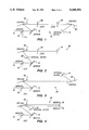
The CPA systems of the prior art employ a variety of stretchers and compressors. FIG. 1 illustrates a two grating pulse stretcher 10 of the prior art. As shown in FIG. 1, the beam enters the stretcher 10 and is reflected by a first mirror 12 to a first diffraction grating 18. The grating 18 passes the diffracted beam on through a first and a second lenses 22, 24 to the second diffraction grating 20. The diffracted beam is incident on grating 20 at the same angle (relative to the grating normal) that it left the first grating 18. The second grating 20 directs the beam to a first vertical retroreflector 14. The first vertical retroreflector 14 reflects the beam on a return path to the second grating 20, the second lens 24, the first lens 22, the first grating 18, and the first mirror 12. The beam is then output by reflecting the beam from the first mirror 12 at a different height than the input beam, allowing mirror 16 to reflect the beam out of the stretcher.
FIG. 2 illustrates another prior art pulse stretcher 26. The pulse stretcher 26 of FIG. 2 only employs a single grating. As shown, the beam enters the stretcher 10 and is reflected by a first mirror 12 to a first grating 18. The first grating 18 passes the diffracted beam on through a first lens 22 to a first vertical retroreflector 14. The first vertical retroreflector 14 reflects the beam back through the first lens 22 to the first grating 18. The symmetry provided by the vertical retroreflector 14 makes this optically identical to the stretcher 10 of FIG. 1. The return path of the beam is completed by traveling from the first grating 18 through the second vertical retroreflector block 28 to the output by way of the first and third mirrors 12, 16.
Similarly, single and dual grating pulse compressors have also been developed. FIG. 3 illustrates a two grating pulse compressor 30. The compressor 30 comprises a first and third mirrors 12, 16; a first vertical retroreflector 14; and a first and second gratings 18, 20. The stretched beam enters the compressor 30 and is reflected by the first mirror 12 to the first grating 18, then to the second grating 20 until the first vertical retroreflector 14 is reached. The beam approaches the second grating 20 at the same angle (relative to the grating normal) that it left from the first grating 18. The first vertical retroreflector 14 reflects the beam back to the second grating 20 and to the first grating 18. The returning beam is then reflected by the first mirror 12 and the third mirror 16 to the output.
A single grating pulse compressor 32 of the prior art is shown in FIG. 4. The single grating pulse compressor 32 comprises a first, second, third, and fourth mirrors 12, 15, 16 and 34; a first vertical retroreflector 14; and a first grating 18. The beam enters the compressor 32 and is reflected by the first mirror 12 to the grating 18. The beam leaves the grating 18 and returns to the grating 18 at the same angle it left with, after being reflected by the second and third mirrors 15, 16 at right angles to each other. The beam is then directed to the first vertical retroreflector 14. The beam returns from the first vertical retroreflector 14 and follows a path through the grating 18, to the third and second mirrors 16, 15, to the grating 18 and then to the first mirror 12. The compressed beam is then output after being reflected by the fourth mirror 34.
One continuing problem with the CPA systems of the prior art has been aligning the input of the stretcher and the input of the compressor. Various combinations of the stretchers and compressors described above can be used, but in order for stretching and compressing to work properly, the input angle of the beam into the stretcher must be adjusted to be precisely the same as the input angle of the beam into the compressor. The input angle can be adjusted by rotating the position of the gratings about their central axes. In systems using multiple gratings, the alignment of the input angles to the stretcher and compressor is very time consuming and laborious since the input angle for each grating must be modified to assure the proper alignment. For example, a typical alignment process for just the stretcher includes repeating the steps of: adjusting the position of the first grating for the stretcher, measuring the input angle to the first grating, modifying the input angle for the second grating, and measuring the input angle for the second grating. The process for measuring the input angle is very laborious and time consuming. It is not uncommon for these steps to be repeated numerous times to obtain the proper input angle just for the stretcher, and the alignment process often takes several hours. Once the stretcher has been aligned, then the compressor must be precisely aligned to have the same input angle. Aligning the compressor is performed in similar manner by repeating the steps of repositioning the gratings and then measuring the input angles. Similarly, the alignment process for the compressor can take several hours.
The significance of the problems involved in properly aligning the stretcher and compressor are heightened by the fact that the stretcher and compressor must be realigned every time a different wavelength pulse is stretched and compressed. Unfortunately, the grating angles for proper operation of CPA are different for different wavelengths. Therefore, each time the laser wavelength is changed, the alignment procedure must be performed for the stretcher and compressor to operate properly.
One prior art method for avoiding the problems associated with realigning the gratings is to make a stretcher and compressor with optical components, namely diffraction gratings, large enough to allow some degree of tunability without having to move them. This is presently not practical due to the technological limitations on the size of the diffraction gratings commercially available. Even using the largest diffraction gratings that are currently available, the grating size would continue to limit tunability. Moreover, even if larger diffraction gratings were able to provide the tunability desired, their cost would make any system including them prohibitively expensive.
Therefore, there is a need for a pulse stretcher and compressor that is very easy to adjust for correct operation of the CPA, or for changes in the wavelength of the laser begin amplified.
SUMMARY OF THE INVENTION
The present invention overcomes the limitations and shortcomings of the prior art with a combined stretcher and compressor. The combined stretcher and compressor of present invention advantageously includes a single grating stretcher portion and a single grating compressor portion. A first mirror, a second mirror, a third mirror, a first diffraction grating, a first lens, and a first vertical retroreflector comprise the stretcher portion. A fourth mirror, a second grating, a horizontal retroreflector, and a second vertical retroreflector preferably comprise the compressor portion. The present invention preferably arranges these components such that the input for stretcher and the input of compressor are parallel beams. The present invention also positions the first grating used for the stretcher in a parallel plane with the second grating used for the compressor with each grating facing in an opposite direction. The gratings are preferably mounted on the same rotatable block. By rotating the block, the input angle to both the stretcher and the compressor are changed by the same amount simultaneously. Any adjustments to the input angle for changes in the laser wavelength can be accommodated by changing a single parameter, namely, the angle of the grating block, and thus, the position of both gratings with respect to the input beams.
The present invention also includes a method for simultaneously aligning the input angle of the stretcher portion and the input angle of the compressor portion of the present invention for proper operation as a CPA. The preferred method preferably comprises the steps of: removing the first and second diffraction gratings; aligning the input beam for the stretcher portion such that it passes through a first and a second alignment holes; aligning the input beam for the compressor portion such that it passes through the first and second alignment holes; mounting the first and second gratings on a mounting block in parallel planes, and rotating the mounting block until the proper input angle for the laser wavelength is reached.
BRIEF DESCRIPTION OF THE DRAWINGS
FIG. 1 is a schematic diagram of a two grating pulse stretcher of the prior art;
FIG. 2 is a schematic diagram of a single grating pulse stretcher of the prior art;
FIG. 3 is a schematic diagram of a two grating pulse compressor of the prior art;
FIG. 4 is a schematic diagram of a single grating pulse compressor of the prior art;
FIG. 5 is a schematic diagram of a preferred embodiment for the pulse stretcher and compressor of the present invention;
FIG. 6 is a top plan view of the preferred embodiment of the pulse stretcher and compressor of the present invention;
FIG. 7 is a side view diagram of the optical path for the pulse stretcher portion of the present invention;
FIG. 8a and 8b are a side view diagram of the optical path for the pulse compressor portion of the present invention; and
FIG. 9 is a perspective view of the preferred embodiment for the mounting block of the present invention.
DETAILED DESCRIPTION OF THE PREFERRED EMBODIMENT
Referring now to FIG. 5, a schematic diagram of the preferred embodiment of a stretcher and compressor 40 constructed in accordance with the present invention will be described. The stretcher and compressor 40 of the present invention preferably comprises a stretcher portion 42 and a compressor portion 44. Each portion 42, 44 has its own input and output, however, the stretcher portion 42 and the compressor portion 44 are precisely aligned with each other for proper operation as a CPA. The stretcher portion 42 and the compressor portion 44 are positioned such that the adjustment of a single parameter is all that is necessary to align both the stretcher portion 42 and the compressor portion 44 with their respective input beams.
As best shown in FIG. 5, the stretcher portion 42 includes a first mirror 46, a first diffraction grating 48, a first lens 50, a second mirror 52, a third mirror 54 and a first vertical retroreflector 56. The stretcher portion 42 preferably uses only a single grating to stretch the pulse. The input to the stretcher portion 42 is received by first mirror 46 and reflected along the X-axis of the stretcher and compressor 40 to the first grating 48. It should be understood that the first mirror 46 is optional, and that the beam could be input directly to the first grating 48 along the X-axis. The first mirror 46 is preferably positioned a predetermined distance from the first grating 48. For example, the first mirror 46 may be positioned 60 centimeters from the first grating 48. The first grating 48 is preferably mounted on a rotatable block 70, as described below, so that the input angle (α) of the beam to the first grating 48 may be adjusted. The diffraction gratings diffract different wavelength components through different angles; sending each different component along a slightly different path through the stretcher or compressor. The second mirror 52 is positioned a predetermined distance away from the first grating 48 generally in the direction of the first mirror 46. For example, the second mirror 52 must be positioned one focal length away from the lens at angle of 90 degrees relative to the beam coming from the grating 48. From the grating 48, the beam is directed toward the second mirror 52, and then reflected back to the first grating 48. The first lens 50 is preferably disposed in the optical path between the first grating 48 and the second mirror 52 such that the beam passes through the lens 50. The two remaining components of the stretcher portion 42 are the third mirror 54 and the first vertical retroreflector 56. The third mirror 54 and the first vertical retroreflector 56 are positioned along the X-axis between the first mirror 46 and the first grating 48. The first vertical retroreflector 56 is positioned to receive an optical beam from the first grating 48 and send a return beam with a parallel path but offset vertically. The first vertical retroreflector 56 accomplishes this with a pair of mirrors mounted at a right angle. Those skilled in the art will realize that the retroreflector 56 could also be a single mirror slightly titled upwards or downwards and with the positions of the other components modified. The first vertical retroreflector 56 is preferably positioned between the first mirror 46 and the first grating 48 proximate the first mirror 46. The third mirror 54 is positioned between first vertical retroreflector 56 and the first grating 48. The third mirror 54 is optically coupled to the first grating 48 to output an out of the plane beam away from the X-axis. Finally, it should be noted that the first mirror 46, first grating 48, first lens 50, second mirror 52, third mirror 54 and first vertical retroreflector 56 can be conventional components used to affect optical beams.
Referring now to FIG. 7, the vertical path of the laser beam through the stretcher portion 42 is shown. The beam is input to the first mirror 46 and reflected towards the first grating 48. The beam is then diffracted by the first grating 48 through the first lens 50 to the second mirror 52. While the beam is shown as passing through first grating 48, the beam is in fact diffracted by the grating 48. The beam is only shown as passing through the first grating 48 for ease of understanding. The beam is reflected by the second mirror 52 back through lens 50 to the first grating 48. The first grating 48 sends the beam toward a first mirror of the first vertical retroreflector 56. The beam is reflected by both mirrors of the first vertical retroreflector 56 back along a path parallel but vertically offset from the entry beam to the first grating 48. The first grating 48 then diffracts the beam a third time through the lens 50 to the mirror 52. Finally, the beam is reflected back through the lens 50 by the second mirror 52, and by the first grating 48 to the third or pick off mirror 54 as the output. FIG. 7 illustrates the vertical spacing differences in the placement of the first mirror 46, the first vertical retroreflector 56, and the third mirror 54.
Referring back to FIG. 5, the preferred embodiment for the compressor portion 44 will be described. The compressor portion 44 preferably includes a fourth mirror 58, a second grating 60, a horizontal retroreflector 62 and a second vertical retroreflector 64. The second grating 60 is preferably positioned on the same mounting block 70 as the first grating 48. The second diffraction grating 60 is preferably mounted in a position parallel to the first grating 48, with the second diffraction grating 60 and the first grating 48 facing in opposite directions. This can be achieved by means of a very simple alignment procedure, external to the stretcher and compressor. The fourth mirror 58 is preferably positioned on the X-axis in a position distal the second diffraction grating 60. The fourth mirror 58 is positioned such that the input beam is reflected to the second diffraction grating 60 along the X-axis in a direction opposite to the input to the first grating 48. It should be noted that the fourth mirror 58 is optional, and the beam could be input directly to the second grating 60. The input angle (β) to the second diffraction grating 60 is advantageously the same as the input angle (α) to the first grating 48 because of the position of the input beams and the parallel positioning of the first grating 48 and the second diffraction grating 60. The horizontal retroreflector 62 is positioned a predetermined distance away from the first grating 48, generally in the direction of the fourth mirror 58. For example, the horizontal retroreflector 62 may be positioned 50 cm at angle of 15 degrees from the X-axis. The beam is directed toward the horizontal retroreflector 62 and then reflected back along a parallel but opposing path to the second grating 60 by the two mirrors of the horizontal retroreflector 62. The final component of the compressor portion 44 is the second vertical retroreflector 64. The second vertical retroreflector 64 is positioned proximate the X-axis to receive a beam from the second diffraction grating 60 since the beams to and from the second vertical retroreflector 64 are parallel to the X-axis. The second vertical retroreflector 64 is preferably positioned about midway between the second diffraction grating 60 and the fourth mirror 58. Like the first vertical retroreflector 56, the second vertical retroreflector 64 is positioned to receive an optical beam from the second diffraction grating 60 and send a return beam with a parallel path but vertically offset. The second vertical retroreflector 64 includes a pair of mirrors mounted at a right angle for this purpose. The fourth mirror 58, second grating 60, horizontal retroreflector 62 and second vertical retroreflector 64 are constructed using conventional optical components as will be understood to those skilled in the art.
Referring now to FIGS. 8a and 8b, the vertical path of the laser beam through the compressor portion 44 is shown. For ease of understanding, the second grating 60 is shown graphically as two parts with the beam passing through the second grating 60. The beam is actually diffracted by the second grating 60 where the beam path is shown in FIGS. 8a and 8b as passing through the grating 60. Only a single grating forms the second grating 60 in the preferred embodiment, and the second grating 60 is only represented by the two parts for ease of understanding. The beam is input into the compressor 44 and reflected along the X-axis by the fourth mirror 58. The beam is then diffracted by the second diffraction grating 60 toward the horizontal retroreflector 62. The horizontal retroreflector 62 shifts the beam horizontally and sends a parallel beam back to the second diffraction grating 60 (as best shown in FIG. 5). The second diffraction grating 60 then diffracts the return beam to the second vertical retroreflector 64. The second vertical retroreflector 64 returns a beam on a parallel path elevated above the input path as best shown in FIGS. 8a and 8b. Both retroreflectors 62, 64 use a pair of mirrors positioned at right angles to provide return paths parallel but opposite in direction to the input beam. The beam is then diffracted by the second diffraction grating 60 toward the horizontal retroreflector 62 which again horizontally shifts the beam but back to its original horizontal position. From the horizontal retroreflector 62, the beam is sent to the second diffraction grating 60 and the diffracted to the output.
FIG. 6 illustrates a top plan view of the preferred embodiment for the stretcher and compressor 40 of the present invention. As shown in FIG. 6, the first grating 48 and the second diffraction grating 60 are mounted on top of the rotatable mounting block 70. The first grating 48 and the second diffraction grating 60 are preferably mounted in parallel planes with the front of each facing in opposite directions. The first grating 48 and the second diffraction grating 60 are slightly offset with just a portion of the gratings 48, 60 overlapping the X-axis. The gratings are preferably firmly attached to the rotatable mounting block 70 by fastening means 72. The fastening means are preferably yaw and pitch mirror mounts conventional in the art.
The top view of FIG. 6 also illustrates the alignment of the input to the stretcher portion 42 and the input to the compressor portion 44. As shown in FIG. 6, the input to the first grating 48 is along the X-axis as is the input to the second diffraction grating 60. In the preferred embodiment, the axis of the input beams is preferably collinear. The present invention preferably provides a first and second alignment means 74, 76 to ensure that the input beams to the gratings 48, 60 are collinear. The first and second alignment means 74, 76 are removable and not used during the normal operation of the stretcher and compressor 40. The first and second alignment means 74, 76 preferably each comprise an member defining an alignment hole through which the beam may pass. The first alignment means 74 is preferably positioned between the first mirror 46 and the first grating 48 or mounting block 70 for alignment purposes. The second alignment means 76 is preferably positioned between the second diffraction grating 60 or mounting block 70 and the fourth mirror 58. Once the alignment means 74, 76 are positioned, the input beam to the stretcher portion 42 is adjusted so that the input beam passes through the holes in both alignment means 74, 76. Similarly, the input beam to the compressor portion 44 is adjusted so that its input beam passes through the holes in both alignment means 74, 76. This ensures that the input beams to both gratings 48, 60 are collinear. Those skilled in the art will realize that this configuration for the alignment means 74, 76 may be modified to ensure that the beams are parallel.
The present invention also includes a preferred method for simultaneously aligning the input angle of tile stretcher portion 42 and the input angle of the compressor portion 44 of the present invention for proper operation as a CPA. The preferred method begins alignment by removing the first and second diffraction gratings 48, 60. Then, the alignment means 74, 76 are positioned between the first mirror 46 and the first grating 48, and the second diffraction grating 60 and the fourth mirror 58, respectively. Once the alignment means 74, 76 are in place, the input beam for the stretcher portion 42 is aligned such that it passes through a first and second alignment holes. Next, the input beam for the compressor portion is aligned such that it passes through the first and second alignment holes. The alignment means 74, 76 are then removed, and the gratings 48, 60 are positioned on the mounting block 70 in parallel planes. The mounting block 70 is then rotated until the proper input angle for the laser wavelength is reached. The position of the diffraction gratings 48, 60 can be further fine tuned using controls on the mounting block 70.
Referring now to FIG. 9, the preferred embodiment for the rotatable mounting block 70 is shown. The rotatable mounting block 70 preferably comprises a base 80, a rotatable top 82, an adjustment means 84, a fine tuning means 86, and fastening means 72. The rotatable top 82 is coupled to the base 80 by the adjustment means 84 and the fine tuning means 86. The adjustment means 84 provides for rotation of the rotatable top 82 with respect to the base 80 about a Y-axis. The rotatable top 82 may be generally moved to the desired position by applying rotation forces directly to the rotatable top 82. Once generally in the position desired, the gratings 48, 60 may be precisely aligned by turning the fine tuning means 86 which cause very minor rotations of the rotatable top 82. The gratings 48, 60 are preferably mounted to the rotatable top 82 using the fastening means 72. The fastening means 72 are preferably mounted spaced apart along parallel planes. The fastening means 72 each have one end securely mounted to the top surface of the rotatable top 82. The fastening means also provide a slot for receiving and holding the gratings 48, 60.
While the present invention has been described with reference to certain preferred embodiments, those skilled in the art will recognize that various modifications may be provided. For example, there may be other embodiments for the stretcher and compressor in addition to those described with reference to FIGS. 5-9. For example, the inputs to the stretcher and compressor may be parallel rather than collinear with the grating being mounted in parallel planes on separate mounting blocks. These and other variations upon and modifications to the preferred embodiment are provided for by the present invention which is limited only by the following claims.

Claims (10)

What is claimed is:
1. A laser pulse stretcher and compressor comprising:
a stretcher portion having a first diffraction grating for receiving a laser pulse and stretching the pulse, the stretcher portion receiving a first input beam to the stretcher portion along a first axis, the first diffraction grating positioned for receiving the first input beam with an input side of the first diffraction grating; and
a compressor portion having a second diffraction grating for receiving a laser pulse and compressing the pulse, the compressor portion receiving a second input beam along a second axis, the second axis parallel to the first axis, the second diffraction grating positioned for receiving the second input beam with an input side of the second diffraction grating, and the second diffraction grating being positioned in a plane parallel to a plane in which the first diffraction grating is positioned.
2. A laser pulse stretcher and compressor comprising:
a stretcher portion having a first diffraction grating for receiving a laser pulse and stretching the pulse, the stretcher portion receiving a first input beam to the stretcher portion along a first axis, the first diffraction grating positioned for receiving the first input beam with an input side of the first diffraction grating; and
a compressor portion having a second diffraction grating for receiving a laser pulse and compressing the pulse, the compressor portion receiving a second input beam along a second axis, the first axis being collinear with the second axis, the second diffraction grating positioned for receiving the second input beam with an input side of the second diffraction grating, and the second diffraction grating being positioned in a plane parallel to a plane in which the first diffraction grating is positioned.
3. A laser pulse stretcher and compressor comprising:
a stretcher portion having a first diffraction grating for receiving a laser pulse and stretching the pulse, the stretcher portion receiving a first input beam to the stretcher portion along a first axis, the first diffraction grating positioned for receiving the first input beam with an input side of the first diffraction grating;
a compressor portion having a second diffraction grating for receiving a laser pulse and compressing the pulse, the compressor portion receiving a second input beam along a second axis, the second axis parallel to the first axis, the second diffraction grating positioned for receiving the second input beam with an input side of the second diffraction grating; and
wherein the first diffraction grating and the second diffraction grating are mounted in parallel planes to a rotatable block for providing single parameter alignment of input angles to the first and second diffraction gratings by rotation of the block.
4. A laser pulse stretcher and compressor comprising:
a stretcher portion having a first diffraction grating, a first mirror, a lens and a retroreflector for receiving a laser pulse and stretching the pulse, the stretcher portion receiving a first input beam to the stretcher portion along a first axis, the first diffraction grating positioned for receiving the first input beam with an input side of the first diffraction grating; the first mirror optically coupled to the first diffraction grating for receiving and transmitting an optical beam; the lens positioned between the first mirror and the first diffraction grating, said lens optically coupling the first diffraction grating and the first mirror, and the retroreflector positioned along the first axis, the retroreflector optically coupled to the first diffraction grating for receiving an optical beam and transmitting the beam back to the diffraction grating along a parallel path; and
a compressor portion having a second diffraction grating for receiving a laser pulse and compressing the pulse, the compressor portion receiving a second input beam along a second axis, the second axis parallel to the first axis, the second diffraction grating positioned for receiving the second input beam with an input side of the second diffraction grating, and the second diffraction grating being positioned in a plane parallel to a plane in which the first diffraction grating is positioned.
5. The apparatus of claim 4, wherein the first mirror is positioned one focal length away from the lens at an angle of about 90 degrees relative to the beam received from the first grating.
6. The apparatus of claim 4, wherein the retroreflector comprises a second mirror and a third mirror, the second mirror and the third mirror positioned in planes at a right angle to each other.
7. The apparatus of claim 4, wherein the retroreflector comprises a single mirror, slightly tiled downwards.
8. A laser pulse stretcher and compressor comprising:
a stretcher portion having a first diffraction grating for receiving a laser pulse and stretching the pulse, the stretcher receiving a first input beam to the stretcher portion along a first axis, the first diffraction grating positioned for receiving the first input beam with an input side of the first diffraction grating; and
a compressor portion having a second diffraction grating, a horizontal retroreflector, and a vertical retroreflector for receiving a laser pulse and compressing the pulse, the compressor portion receiving a second input beam along a second axis, the second axis parallel to the first axis, the second diffraction grating positioned for receiving the second input beam with an input side of the second diffraction grating, and the second diffraction grating being positioned in a plane parallel to a plane in which the first diffraction grating is positioned, the horizontal retroreflector positioned to receive an optical beam from the second grating, the horizontal retroreflector optically coupled to the second diffraction grating to receive an optical beam and transmit the beam back to the second diffraction grating along a parallel path shifted in the horizontal direction, and the vertical retroreflector positioned to receive an optical beam from the second grating, the vertical retroreflector optically coupled to the second diffraction grating to receive an optical beam and transmit the beam back to the second diffraction grating along a parallel path shifted in the vertical direction.
9. The apparatus of claim 8, wherein the vertical and horizontal retroreflectors each comprises a first mirror and a second mirror, the first mirror and the second mirror positioned in planes at a right angle to each other.
10. A laser pulse stretcher and compressor comprising:
a rotatable block;
a stretcher portion having a first diffraction grating for receiving a laser pulse and stretching the pulse, the stretcher portion receiving a first input beam to the stretcher portion at a first angle, the first diffraction grating positioned for receiving the first input beam with an input side of the first diffraction grating, the first angle measured between a first axis and the input side of the first diffraction grating, the first diffraction grating mounted on the rotatable block; and
a compressor portion having a second diffraction grating for receiving a laser pulse and compressing the pulse, the compressor portion receiving a second input beam at a second angle, the second diffraction grating positioned for receiving the second input beam with an input side of the second diffraction grating, the second angle measured between a second axis and the input side of the second diffraction grating, the second diffraction grating mounted on the rotatable block, the second diffraction grating positioned relative to the first diffraction grating such that the second angle is equal to the first angle and a change in the first angle resulting from a displacement in the position of the first diffraction grating caused by rotation of the rotatable block results in an identical change in the second angle.
US08/052,778 1993-04-26 1993-04-26 Laser pulse stretcher and compressor with single parameter wavelength tunability Expired - Lifetime US5349591A (en)

Priority Applications (1)

Application Number Priority Date Filing Date Title
US08/052,778 US5349591A (en) 1993-04-26 1993-04-26 Laser pulse stretcher and compressor with single parameter wavelength tunability

Applications Claiming Priority (1)

Application Number Priority Date Filing Date Title
US08/052,778 US5349591A (en) 1993-04-26 1993-04-26 Laser pulse stretcher and compressor with single parameter wavelength tunability

Publications (1)

Publication Number Publication Date
US5349591A true US5349591A (en) 1994-09-20

Family

ID=21979829

Family Applications (1)

Application Number Title Priority Date Filing Date
US08/052,778 Expired - Lifetime US5349591A (en) 1993-04-26 1993-04-26 Laser pulse stretcher and compressor with single parameter wavelength tunability

Country Status (1)

Country Link
US (1) US5349591A (en)

Cited By (31)

* Cited by examiner, † Cited by third party
Publication number Priority date Publication date Assignee Title
US5602677A (en) * 1993-05-18 1997-02-11 Thomson-Csf Dispersive optical delay line and use thereof for the compression/expansion of laser pulses
FR2772937A1 (en) * 1997-12-19 1999-06-25 Thomson Csf Optical pulse expander/compressor
US5960016A (en) * 1997-06-05 1999-09-28 The Regents Of The University Of California Aberration-free, all-reflective laser pulse stretcher
US6116900A (en) 1997-11-17 2000-09-12 Lumachem, Inc. Binary energizer and peroxide delivery system for dental bleaching
US6151345A (en) * 1998-07-07 2000-11-21 Dtm Corporation Laser power control with stretched initial pulses
US6157661A (en) 1999-05-12 2000-12-05 Laserphysics, Inc. System for producing a pulsed, varied and modulated laser output
US6282013B1 (en) 1997-04-30 2001-08-28 Lasermed, Inc. System for curing polymeric materials, such as those used in dentistry, and for tailoring the post-cure properties of polymeric materials through the use of light source power modulation
US6384099B1 (en) 1997-04-30 2002-05-07 Laser Med. Inc. Method for curing polymeric materials, such as those used in dentistry, and for tailoring the post-cure properties of polymeric materials through the use of light source power modulation
US6389045B1 (en) 1999-04-19 2002-05-14 Lambda Physik Ag Optical pulse stretching and smoothing for ArF and F2 lithography excimer lasers
US6392807B1 (en) * 2000-12-22 2002-05-21 Avanex Corporation Tunable chromatic dispersion compensator utilizing a virtually imaged phased array and folded light paths
US6602074B1 (en) 1997-10-29 2003-08-05 Bisco, Inc. Dental composite light curing system
US6603600B2 (en) * 2001-11-21 2003-08-05 Coherent, Inc. Chirped pulse amplification method and apparatus
US20030179804A1 (en) * 2002-03-22 2003-09-25 Cook Lacy G. Method and laser beam directing system with rotatable diffraction gratings
US6739728B2 (en) 2002-04-08 2004-05-25 The Regents Of The University Of California Short pulse laser stretcher-compressor using a single common reflective grating
FR2872592A1 (en) * 2004-07-02 2006-01-06 Thales Sa AMPLIFIER CHAIN FOR THE GENERATION OF ULTRACOURSE LIGHT PULSES OF DIFFERENT PULSE STRESSES
US6996141B1 (en) * 1999-07-08 2006-02-07 Carl Zeiss Smt Ag Device for reducing the peak power of a pulsed laser light source
CN100526964C (en) * 2006-07-28 2009-08-12 中国科学院上海光学精密机械研究所 Method for regulating parallelism of multiple pairs of raster
US20110026105A1 (en) * 2009-08-03 2011-02-03 Lawrence Livermore National Security, Llc Dispersion Compensation in Chirped Pulse Amplification Systems
US20130265756A1 (en) * 2010-09-10 2013-10-10 Martin Professional A/S Illumination Device With Split Beam Effect
US8618470B2 (en) 2005-11-30 2013-12-31 Board Of Trustees Of Michigan State University Laser based identification of molecular characteristics
US8633437B2 (en) 2005-02-14 2014-01-21 Board Of Trustees Of Michigan State University Ultra-fast laser system
US8675699B2 (en) 2009-01-23 2014-03-18 Board Of Trustees Of Michigan State University Laser pulse synthesis system
US8861075B2 (en) 2009-03-05 2014-10-14 Board Of Trustees Of Michigan State University Laser amplification system
WO2015056049A1 (en) 2013-10-15 2015-04-23 Uab Mgf Sviesos Konversija Laser pulse stretcher and compressor
US9066777B2 (en) 2009-04-02 2015-06-30 Kerr Corporation Curing light device
JP2017033019A (en) * 2016-10-28 2017-02-09 株式会社島津製作所 Method for amplifying chirp pulse in laser device
US9572643B2 (en) 1998-01-20 2017-02-21 Kerr Corporation Apparatus and method for curing materials with radiation
US9693846B2 (en) 2009-04-02 2017-07-04 Kerr Corporation Dental light device
US9825419B2 (en) 2014-02-28 2017-11-21 Imra America, Inc. Multi-wavelength, ultrashort pulse generation and delivery, with applications in microscopy
WO2018010984A1 (en) * 2016-07-13 2018-01-18 Thales Compact and high average power compressor
CN113984222A (en) * 2021-10-28 2022-01-28 中山光子科学中心 On-line measuring device and method for wavefront distortion of grating compressor

Citations (3)

* Cited by examiner, † Cited by third party
Publication number Priority date Publication date Assignee Title
US4928316A (en) * 1988-02-04 1990-05-22 Bell Communications Research, Inc. Optical systems and methods based upon temporal stretching, modulation and recompression of ultrashort pulses
US5095487A (en) * 1990-12-14 1992-03-10 The University Of Rochester System for generating pluralities of optical pulses with predetermined frequencies in a temporally and spatially overlapped relationship
US5235606A (en) * 1991-10-29 1993-08-10 University Of Michigan Amplification of ultrashort pulses with nd:glass amplifiers pumped by alexandrite free running laser

Patent Citations (3)

* Cited by examiner, † Cited by third party
Publication number Priority date Publication date Assignee Title
US4928316A (en) * 1988-02-04 1990-05-22 Bell Communications Research, Inc. Optical systems and methods based upon temporal stretching, modulation and recompression of ultrashort pulses
US5095487A (en) * 1990-12-14 1992-03-10 The University Of Rochester System for generating pluralities of optical pulses with predetermined frequencies in a temporally and spatially overlapped relationship
US5235606A (en) * 1991-10-29 1993-08-10 University Of Michigan Amplification of ultrashort pulses with nd:glass amplifiers pumped by alexandrite free running laser

Cited By (43)

* Cited by examiner, † Cited by third party
Publication number Priority date Publication date Assignee Title
US5602677A (en) * 1993-05-18 1997-02-11 Thomson-Csf Dispersive optical delay line and use thereof for the compression/expansion of laser pulses
US6282013B1 (en) 1997-04-30 2001-08-28 Lasermed, Inc. System for curing polymeric materials, such as those used in dentistry, and for tailoring the post-cure properties of polymeric materials through the use of light source power modulation
US6384099B1 (en) 1997-04-30 2002-05-07 Laser Med. Inc. Method for curing polymeric materials, such as those used in dentistry, and for tailoring the post-cure properties of polymeric materials through the use of light source power modulation
US5960016A (en) * 1997-06-05 1999-09-28 The Regents Of The University Of California Aberration-free, all-reflective laser pulse stretcher
US6602074B1 (en) 1997-10-29 2003-08-05 Bisco, Inc. Dental composite light curing system
US6116900A (en) 1997-11-17 2000-09-12 Lumachem, Inc. Binary energizer and peroxide delivery system for dental bleaching
FR2772937A1 (en) * 1997-12-19 1999-06-25 Thomson Csf Optical pulse expander/compressor
US9572643B2 (en) 1998-01-20 2017-02-21 Kerr Corporation Apparatus and method for curing materials with radiation
US9622839B2 (en) 1998-01-20 2017-04-18 Kerr Corporation Apparatus and method for curing materials with radiation
US6151345A (en) * 1998-07-07 2000-11-21 Dtm Corporation Laser power control with stretched initial pulses
US6389045B1 (en) 1999-04-19 2002-05-14 Lambda Physik Ag Optical pulse stretching and smoothing for ArF and F2 lithography excimer lasers
US6157661A (en) 1999-05-12 2000-12-05 Laserphysics, Inc. System for producing a pulsed, varied and modulated laser output
US6996141B1 (en) * 1999-07-08 2006-02-07 Carl Zeiss Smt Ag Device for reducing the peak power of a pulsed laser light source
US6392807B1 (en) * 2000-12-22 2002-05-21 Avanex Corporation Tunable chromatic dispersion compensator utilizing a virtually imaged phased array and folded light paths
US6603600B2 (en) * 2001-11-21 2003-08-05 Coherent, Inc. Chirped pulse amplification method and apparatus
US20030179804A1 (en) * 2002-03-22 2003-09-25 Cook Lacy G. Method and laser beam directing system with rotatable diffraction gratings
US6792028B2 (en) * 2002-03-22 2004-09-14 Raytheon Company Method and laser beam directing system with rotatable diffraction gratings
US6739728B2 (en) 2002-04-08 2004-05-25 The Regents Of The University Of California Short pulse laser stretcher-compressor using a single common reflective grating
US7729045B2 (en) * 2004-07-02 2010-06-01 Thales Amplifier chain for generating ultrashort different width light pulses
US20080043789A1 (en) * 2004-07-02 2008-02-21 Vincent Moro Amplifier Chain for Generating Ultrashort Different Width Light Pulses
FR2872592A1 (en) * 2004-07-02 2006-01-06 Thales Sa AMPLIFIER CHAIN FOR THE GENERATION OF ULTRACOURSE LIGHT PULSES OF DIFFERENT PULSE STRESSES
WO2006003185A1 (en) * 2004-07-02 2006-01-12 Thales Amplifier chain for generating ultrashort different width light pulses
US8633437B2 (en) 2005-02-14 2014-01-21 Board Of Trustees Of Michigan State University Ultra-fast laser system
US8618470B2 (en) 2005-11-30 2013-12-31 Board Of Trustees Of Michigan State University Laser based identification of molecular characteristics
CN100526964C (en) * 2006-07-28 2009-08-12 中国科学院上海光学精密机械研究所 Method for regulating parallelism of multiple pairs of raster
US8675699B2 (en) 2009-01-23 2014-03-18 Board Of Trustees Of Michigan State University Laser pulse synthesis system
US8861075B2 (en) 2009-03-05 2014-10-14 Board Of Trustees Of Michigan State University Laser amplification system
US9987110B2 (en) 2009-04-02 2018-06-05 Kerr Corporation Dental light device
US9066777B2 (en) 2009-04-02 2015-06-30 Kerr Corporation Curing light device
US9693846B2 (en) 2009-04-02 2017-07-04 Kerr Corporation Dental light device
US9730778B2 (en) 2009-04-02 2017-08-15 Kerr Corporation Curing light device
US8780440B2 (en) * 2009-08-03 2014-07-15 Lawrence Livermore National Security, Llc Dispersion compensation in chirped pulse amplification systems
US20110026105A1 (en) * 2009-08-03 2011-02-03 Lawrence Livermore National Security, Llc Dispersion Compensation in Chirped Pulse Amplification Systems
US8702276B2 (en) * 2010-09-10 2014-04-22 Martin Professional A/S Illumination device with split beam effect
US20130265756A1 (en) * 2010-09-10 2013-10-10 Martin Professional A/S Illumination Device With Split Beam Effect
WO2015056049A1 (en) 2013-10-15 2015-04-23 Uab Mgf Sviesos Konversija Laser pulse stretcher and compressor
US9825419B2 (en) 2014-02-28 2017-11-21 Imra America, Inc. Multi-wavelength, ultrashort pulse generation and delivery, with applications in microscopy
WO2018010984A1 (en) * 2016-07-13 2018-01-18 Thales Compact and high average power compressor
FR3054082A1 (en) * 2016-07-13 2018-01-19 Thales COMPACT COMPACTOR WITH HIGH AVERAGE POWER
CN109478753A (en) * 2016-07-13 2019-03-15 泰勒斯公司 Compact high-average power compressor
JP2019527478A (en) * 2016-07-13 2019-09-26 タレス Compact and high average power compressor
JP2017033019A (en) * 2016-10-28 2017-02-09 株式会社島津製作所 Method for amplifying chirp pulse in laser device
CN113984222A (en) * 2021-10-28 2022-01-28 中山光子科学中心 On-line measuring device and method for wavefront distortion of grating compressor

Similar Documents

Publication Publication Date Title
US5349591A (en) Laser pulse stretcher and compressor with single parameter wavelength tunability
JP2944692B2 (en) Semiconductor device structure
KR100731799B1 (en) Laser beam machine
US6423925B1 (en) Apparatus and method for combining multiple laser beams in laser material processing systems
US20040240088A1 (en) Compact precision beam manipulators
JPS63229888A (en) Laser wavelength controlling device
US20020176149A1 (en) Variable optical source
CN106019580B (en) A kind of flexible wide type optical filter with ultra-wide tuning range
US7769068B2 (en) Spectral-narrowing diode laser array system
JP4093183B2 (en) Laser processing equipment
EP1041422B1 (en) Laser apparatus for simultaneously generating a plurality of mutually perpendicular laser planes from a single laser source
BG63517B1 (en) Method and device for the connection and adjustment of optical products, components, modules, devices and systems
US6084717A (en) Laser beam splitter
US5072313A (en) Constant-deviation reflector
US4815820A (en) Method and apparatus for aligning a diffraction grating for tuning the output of a laser
US7088517B2 (en) Beam splitter device or laser-scanning microscope
DE102010052989A1 (en) Beam control with a thermally anisotropic medium
WO2003003058A2 (en) Manufacturing technique for optical fiber array
US6819429B2 (en) Multi-pass optical spectrum analyzer having a polarization-dependent tunable filter
US20220342201A1 (en) Micro-electro-mechanical system (mems) micro-mirror array (mma) steered high-power laser transmitter
CN213184959U (en) Multi-pass laser pulse widening device
CA2358219A1 (en) Collimator, collimator array and method of producing those member
EP0064784B1 (en) Optical branch coupler
US5020074A (en) Laser alignment system
US3659926A (en) Beam displacer

Legal Events

Date Code Title Description
AS Assignment

Owner name: POSITIVE LIGHT INC., CALIFORNIA

Free format text: ASSIGNMENT OF ASSIGNORS INTEREST;ASSIGNORS:WESTON, JEREMY;WHITE, WILLIAM E.;REEL/FRAME:006541/0627

Effective date: 19930423

STPP Information on status: patent application and granting procedure in general

Free format text: APPLICATION UNDERGOING PREEXAM PROCESSING

FPAY Fee payment

Year of fee payment: 4

FPAY Fee payment

Year of fee payment: 8

FEPP Fee payment procedure

Free format text: PAT HOLDER NO LONGER CLAIMS SMALL ENTITY STATUS, ENTITY STATUS SET TO UNDISCOUNTED (ORIGINAL EVENT CODE: STOL); ENTITY STATUS OF PATENT OWNER: LARGE ENTITY

REFU Refund

Free format text: REFUND - PAYMENT OF MAINTENANCE FEE, 12TH YR, SMALL ENTITY (ORIGINAL EVENT CODE: R2553); ENTITY STATUS OF PATENT OWNER: LARGE ENTITY

FPAY Fee payment

Year of fee payment: 12