US5337664A - Printing press with blanket cylinder throw off apparatus and method - Google Patents
Printing press with blanket cylinder throw off apparatus and method Download PDFInfo
- Publication number
- US5337664A US5337664A US08/045,543 US4554393A US5337664A US 5337664 A US5337664 A US 5337664A US 4554393 A US4554393 A US 4554393A US 5337664 A US5337664 A US 5337664A
- Authority
- US
- United States
- Prior art keywords
- cylinders
- blanket
- throw
- axes
- blanket cylinders
- Prior art date
- Legal status (The legal status is an assumption and is not a legal conclusion. Google has not performed a legal analysis and makes no representation as to the accuracy of the status listed.)
- Expired - Lifetime
Links
Images


Classifications
-
- B—PERFORMING OPERATIONS; TRANSPORTING
- B41—PRINTING; LINING MACHINES; TYPEWRITERS; STAMPS
- B41F—PRINTING MACHINES OR PRESSES
- B41F13/00—Common details of rotary presses or machines
- B41F13/08—Cylinders
- B41F13/24—Cylinder-tripping devices; Cylinder-impression adjustments
- B41F13/26—Arrangement of cylinder bearings
- B41F13/28—Bearings mounted eccentrically of the cylinder axis
Definitions
- This invention generally relates to an offset printing press and more particularly to such a printing press with a pair of blanket cylinders movably mounted by a throw off apparatus to enable separation from each other and from a pair of plate cylinders.
- FIGS. 1A and 1B shown is a schematic view of one end of a conventional, or prior art, offset press 10 including a pair of substantially identical plate cylinders 12A and 12B mounted for rotation about fixed axes of rotation 20A and 20B and which carry an engraved plate (not shown) of images to be printed on a web of paper 13 passing between a pair of blanket cylinders 14A and 14B.
- Each of the blanket cylinders 14A and 14B carry cylindrical blankets 14A' and 14B' respectively wrapped therearound.
- the images engraved on the plates of plate cylinders 12A and 12B are transferred as inked images to the blankets 14A' and 14B' of plate cylinder 14A and 14B
- the inked images carried by the blankets 14A' and 14B' are transferred to opposite sides of the paper web 13.
- For each of the plate cylinders 12A and 12B there is an inking train of rollers to deliver ink to the plate cylinders 12A and 12B and a dampening train of rollers to deliver dampening liquid to the plate cylinders 12A and 12B which are conventional and therefore not shown.
- Those inking train rollers and dampening liquid train of rollers are in generally tandem rolling contact with each other and ultimately, at their ends, with the plate cylinders 12A and 12B and are relatively fixed and immovable during normal use of the press.
- the offset printing press 10 is shown in an operational position in which the plate cylinders 12A and 12B are in rolling transfer contact with the blankets 14A' and 14B' of the blanket cylinders 14A and 14B, respectively, and the paper web 13 is run through the contact nib between the pair of blanket cylinders 14A and 14B.
- the blankets 14A' and 14B' must be periodically removed from the surface of the blanket cylinders 14A and 14B. When worn, the blankets 14A' and 14B' are removed and replaced. Accordingly, the pair of blanket cylinders 14A and 14B are movably mounted by means of a throw off apparatus for separation and creation of throw off gaps. Referring to FIG.
- a gap 41 is created between the blanket cylinders 14A and 14B and gaps 40A and 40B are created between the plate cylinders 12A and 12B and the blanket cylinders 14A and 14B, respective.
- the blankets 14A' and 14B' or other like blankets are mounted to and removed from through the gaps 40A, 40B and 41. Additionally, the creation of throw off gap 41 and throw off gaps 40A and 40B are needed to install and remove plates from the plate cylinders 12A and 12B and blankets 14A' and 14B' from the corresponding blanket cylinders 14A and 14B, respectively.
- a throw off gap 41 is needed to provide space between the blanket cylinders in case of a break in the web 13 during printing which consequently can lead to a web wrap-up around the blanket cylinders.
- the gaps provide room for the broken web to wrap and accumulate around the blanket cylinders thereby preventing possible damage to the blanket cylinders.
- the throw off apparatus includes a drive linkage 15 pivotally connected to a peripheral arm of an eccentric member 44A which mounts axle 24A of the blanket cylinders 14A, and an interconnecting member 17 pivotally linking together another peripheral arm of the eccentric member 44A with a peripheral arm of another like eccentric member 44B mounting rotary axle 24B of the blanket cylinder 14B.
- the eccentric members 44A and 44B are mounted for rotation about fixedly mounted axes 25A and 25B, respectively, which are offset from the rotary axes 24A and 24B, respectively, of the blanket cylinders 14A and 14B.
- the drive linkage 15 is moved by a conventional drive (not shown) to turn the eccentric members 44A and 44B in a counterclockwise direction from the operational position shown in FIG. 1A, as shown by arrows 42 and 47, FIG. 1A.
- This counterclockwise rotation causes the blanket cylinders 14A and 14B to move downwardly from the plate cylinders 12A and 12B and away from each other to create the necessary throw off gap 41 between the blanket cylinders and the pair of gaps 40A and 40B between blanket cylinders 12A and 12B and the pair of plate cylinders 12A and 12B, respectively.
- both of the central axes of rotation 20A and 20B of the plate cylinders 12A and 12B are offset approximately thirty degrees from the blanket cylinders 14A and 14B and have axes substantially misaligned from lateral alignment with the central axes of rotation 24A and 24B of the blanket cylinders 14A and 14B.
- the rolling contact between the inking and dampening train of rollers and the plate cylinders 12A and 12B and between the plate cylinders 12A and 12B and movably mounted blanket cylinders 14A and 14B results in vibration between the blanket cylinders 14A and 14B and between the plate cylinders 12A and 12B and the blanket cylinders 14A and 14B, respectively.
- This vibration in a lateral direction generally transverse to the rotary axes results in momentary losses of proper printing pressure between the plate cylinders 12A and 12B and the blanket cylinders 14A and 14B.
- This vibration between the cylinders creates an uneven ink transfer from the plate cylinder to the blanket cylinder 14A and 14B.
- this relatively vibrational movement between the blanket cylinders 14A and 14B and the plate cylinders 12A and 12B and between the blanket cylinders 14A and 14B in the misaligned printing press 10 reduces the quality of the printed image on the paper web 13 passed between the blanket cylinders.
- a printing press having a pair of plate cylinders with each having a cylindrical body and a central axis of rotation, means for mounting the axes of the plate cylinders in a parallel spaced relationship and a pair of blanket cylinders located adjacent the plate cylinders with each having a cylindrical body and a rotary axis parallel to the axes of the plate cylinders, with a blanket cylinder throw off apparatus comprising means for mounting the blanket cylinders in an operative position with their axes of rotation in lateral alignment with the axes of rotation of the pair of plate cylinders and with the cylindrical bodies of the blanket cylinders in abutting relationship with each other and with the pair of plate cylinders, respectively, and means for adjusting the mounting means to move the blanket cylinders to a throw off position in which both their rotary axes are out of lateral alignment with the axes of rotation of the plate cylinders to create throw off gaps between the pair of blanket cylinders and the pair of plate
- the adjusting means includes means for mounting the rotary axes for pivotal movement between alignment with the axes of rotation of the plate cylinders to throw off locations on opposite sides of lateral alignment between the axes of rotation of the plate cylinders.
- Means for the rotary axes of both of said blanket cylinders are pivoted about a common pivot axis located substantially midway between the axes of rotation of the plate cylinders.
- a linkage between the pivoting means and the blanket cylinders separates them in response to pivoting of the blanket cylinders to the nonoperative throw off position in which they are out of alignment with the axes of rotation of the plate cylinders.
- the object of the invention is also partly obtained by providing a printing press, having a pair of plate cylinders with each having a cylindrical body and a central axis of rotation, means for mounting the axes of the plate cylinders in fixed, parallel spaced relationship and a pair of blanket cylinders located adjacent the plate cylinders with each having a cylindrical body and a rotary axis parallel to the axes of the plate cylinders, with a blanket cylinder throw off apparatus comprising means for mounting the blanket cylinders for movement between an operative position in which the pair of blanket cylinders are in engagement with the pair of plate cylinders, respectively, and a throw off position in which a throw off gap exists between the pair of blanket cylinders and the pair of plate cylinders, respectively, means for maintaining the plate cylinders in a stationary position when the blanket cylinders are moved from the throw off position, and a linkage assembly including a pivotal linkage between a relatively fixed location and the rotary axes of the blanket cylinders to separate the blanket cylinders
- Obtainment of the object is further achieved by providing a method of operating an offset printing press having plate cylinders and blanket cylinders, comprising the steps of (1) moving a pair of blanket cylinders to an operating position in which they are in substantial alignment with a pair of plate cylinders, (2) printing on a web passing between the blanket cylinders while the blanket cylinders are in the operating position in substantial alignment with the plate cylinders, (3) moving the blanket cylinder to a throw off position in which the blanket cylinders are misaligned with the plate cylinders to create throw off gaps that enable removal of printing blankets carried by the blanket cylinders, (4) returning the blanket cylinders to the operating position in which they are substantially aligned with the plate cylinders and (5) after the blanket cylinders are returned to the operating position in which they are again substantially aligned with the plate cylinders, operating the press to print on the web with printing blankets carried by the blanket cylinders.
- said step of moving is performed by simultaneously pivoting both blanket cylinders around a pivot axis substantially midway between the plate cylinders and the blanket cylinders are moved apart for each other in response to movement of the blanket cylinder to the throw off position.
- FIG. 1A is a schematic side view of a conventional offset printing press of the PRIOR ART illustrating a pair of plate cylinders and a pair of blanket cylinders in the operative position;
- FIG. 1B is a schematic end view of a conventional offset printing press of the PRIOR ART illustrating a pair of plate cylinders and a pair of blanket cylinders in an inoperative throw off position;
- FIG. 2A is a schematic end view of the preferred embodiment of the relevant part of a printing press of the present invention which relates to the blanket cylinder throw off apparatus and a pair of blanket cylinders between the operative position in which they are aligned with the plate cylinders to reduce vibration to a throw off position; and
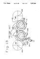
- FIG. 2B is a schematic end view of the preferred embodiment of the printing press of FIG. 2A in which the throw off apparatus in the printing press has been adjusted to move the pair of blanket cylinders to throw off position.
- the preferred embodiment of the printing press 32 of the present invention is shown having a pair of plate cylinders 12A and 12B, each having a cylindrical body 22A and 22B and a central axis of rotation 20A and 20B.
- the axes 20A and 20B of the plate cylinders 12A and 12B are mounted in a fixed, parallel, spaced relationship in the printing press by conventional bearing frames (not shown).
- On opposite sides of the each of the plate cylinders 12A and 12B are an inking train of rollers and a dampening liquid train of rollers, the end rollers of which are in rolling contact with the plate cylinders at all times. These are also relatively fixedly mounted.
- the blanket cylinders 14A and 14B have cylindrical bodies 30A and 30B and are mounted for rotation about rotary axes 24A and 24B which are parallel to the central axes of rotation 20A and 20B of the plate cylinders 12A and 12B, respectively.
- the blanket cylinders are mounted out of alignment with the plate cylinders in order to permit pivotal movement of the blanket cylinders 14A and 14B about separate eccentric axes 25A and 25B off the surfaces of the plate cylinders 12A and 12B. Once this separation is achieved, then additional pivotal movement to separate the blanket cylinders 14A and 14B form each other is enabled.
- Located adjacent the plate cylinders 12A and 12B are a pair of connected blanket cylinders 14A and 14B, respectively.
- the blanket cylinders 14A, 14B are shown mounted in the operative position with a web of paper 13 passing through the blanket cylinders 14A and 14B which are in rolling contact with each other through the web 13 and with the plate cylinders 12A and 12B, respectively.
- the rotary axes 24A and 24B of the blanket cylinders 14A and 14B are mounted in substantial lateral alignment with the axes of rotation 20A and 20B of the plate cylinders 12A and 12B. As seen in FIG.
- the cylindrical bodies 30A and 30B, of the blanket cylinders 14A and 14B are in abutting relationship with each other and with the pair of plate cylinders 12A and 12B. It has been found that this lateral alignment of the blanket cylinders 14A and 14B with the plate cylinders 12A and 12B stabilizes blanket cylinders 14A and 14B to reduce vibration between the blanket cylinders themselves and between the blanket cylinders and their associated plate cylinders during operation.
- the blanket cylinders are mounted to eccentric members 45A and 45B for rotation about their rotary axes 24A and 24B.
- the eccentric members are mounted for rotation about eccentric axes 27A and 27B.
- the relationship between the pivot axle of eccentric members 45A and 45B and the rotary axes 24A and 24B is rotary axis - pivot axis - pivot axis - rotary axis - rotary axis.
- this new pivotal arrangement and increased gap is possible in part because an entirely separate apparatus is provided for creating the throw off gaps 43A and 43B between the blanket cylinders 14A and 14B and the plate cylinders 12A and 12B.
- this separate mechanism is a circular frame plate 46 which carries the pivot axes 27A and 27B of the eccentric members 45A and 45B and is mounted for rotation about a center axis 49 located substantially midway between the plate cylinders 12A and 12B and is laterally aligned with the pivot axes 27A and 27B.
- the blanket cylinders 14A and 14B swing open like opposite sections of a revolving door to create gaps 43A and 43B on the order of eighty mils which is substantially larger than the approximately forty-five mil gaps created by the throw off apparatus of the printing press 10 of FIGS. 1A and 1B.
- the swinging or pivotal movement of the blanket cylinders 14A and 14B about axis 49 causes relative rotation of the eccentric members 45A and 45B in the direction of arrows 57 and 59 to create the gap 39.
- the frame plate 46 is rotated in the direction of arrow 51, FIG. 1A, in order to adjust the throw off apparatus 26 to the throw off position shown in FIG. 2A.
- Adjustable stops 55 and 65 prevent overtravel of the throw off apparatus 26 to the operative position.
- both of the rotary axes 24A and 24B are out of lateral alignment with the axes of rotation 20A and 20B of the stationary plate cylinders 12A and 12B.
- the rotary axes 24A and 24B are moved to opposite sides of lateral alignment between the axes of rotation 20A and 20B of the plate cylinders 12A and 12B with axis 24A being above alignment and axis 24B being an equal amount below alignment.
- the plate cylinders 12A and 12B are maintained in a stationary position during movement of the throw off apparatus 26 from the operative position to the throw off position. In this throw off position, throw off gaps 39 between blanket cylinders 14A and 14B and a pair throw off gaps 43A and 43B between the blanket cylinders and the pair of plate cylinders 12A and 12B, as described above, are provided.
- the rotary axes 24A and 24B of the pair of blanket cylinders 14A and 14B are carried by eccentric members 45A and 45B, respectively, on opposite sides of alignment with the center 49 of the circular frame 46 and the axes 20A and 20B.
- the axis of rotation 24B of blanket cylinder 14B is pivoted to a throw off location below the lateral alignment position.
- the axis of rotation 24A of blanket cylinder 14A is moved to a throw off location above the lateral alignment with the axes of rotation 20A and 20B of the plate cylinders 12A and 12B.
- a conventional drive (not shown) moves a drive link member 36 pivotally attached to a mounting plate 60 to rotate the circular frame 46. Stop members 55 and 65 prevent overtravel of the circular frame in a rotary direction beyond a position corresponding to the operative position of the blanket cylinders 14A and 14B shown in FIG. 2A.
- the eccentric members 44A and 44B carried by the circular frame 46 and mounted to the rotary axes 24A and 24B of the blanket cylinders 14A and 14B move the blanket cylinders in synchronization to create a throw off gap 39, FIG. 2B, between the blanket cylinders when the throw off gaps 43A and 43B are created between the blanket cylinders and the pair of plate cylinders 12A, 12B in response to the pivotal movement of the eccentric axes 27A and 27B about pivot axis 49.
- This synchronized movement is achieved by virtue of linkage assembly linked between a relative fixed location 56 and the eccentric members 45A and 45B to cause them to rotate about their axes 27A and 27B.
- a pivotal, adjustable linkage member 52 pivotally interconnects a relatively fixed mounted bracket 56 to a peripheral arm of the eccentric member 45B.
- the linkage member 52 interconnected with the fixed location 56 is directly linked to the rotary axis 24B of one of the pair of blanket cylinders 14B through the eccentric member 45B.
- Eccentric member 45B is pivotally connected through another pivotal, adjustable linkage member 54 a peripheral arm of eccentric member 45A.
- linkage 52 is linked through eccentric member 45A to the axis of rotation 24A of blanket cylinder 14A.
- the linkage member 52 is thus indirectly linked through the other linkage member 54 and eccentric member 45B to the rotary axis 24A of the other blanket cylinder 14A.
- This linkage assembly causes the eccentric members 45A and 45B to rotate in the direction of arrows 57 and 59 to separate the blanket cylinders 14A and 14B from each other to create a throw off gap 39 when the blanket cylinders are rotated to the throw off position in the direction of arrow 51 and to join the blanket cylinders to eliminate the throw off gap when the blanket cylinders 14A and 14B are pivoted in the opposite direction.
- the pair of eccentric members 45A and 45B which mount the rotary axes 24A and 24B of the blanket cylinders 14A and 14B for rotary movement, selectively pivot the blanket cylinders toward and away from each other.
- the removed printing blankets 14A' and 14B' are exchanged with other printing blankets when the blanket cylinders are in the throw off position.
- the circular frame 46 is moved in a counterclockwise direction opposite to that of arrow 51 relative to the blanket cylinders to the aligned operating position to print on the web 13 of paper with the exchanged or cleaned printing blankets.
- the method of the invention can be practiced with any other offset printing press having a pair of blanket cylinders with a pair of rotary axes parallel to the axes of a pair of plate cylinders.
- an offset printing press having plate cylinders and blanket cylinders is operated by (1) moving a pair of blanket cylinders to an operating position in which the blanket cylinders are in substantial alignment with a pair of plate cylinders to reduce adverse vibration (2) printing on a web passing between the blanket cylinders while the blanket cylinders are in the operating position in substantial alignment with the plate cylinders, (3) moving the blanket cylinder to a throw off position in which the blanket cylinders are misaligned with the plate cylinders to create a throw off gap that enables changing printing blankets carried by the blanket cylinders, (4) returning the blanket cylinders to the operating position in which they are substantially aligned with the plate cylinders, and (5) after the blanket cylinders are returned to the operating position in which they are substantially aligned with the plate cylinders, operating the press to print on the web with the printing blankets carried by the blanket cylinders.
- the blanket cylinders are moved to a throw off position by simultaneously pivoting both blanket cylinders 14A, 14B around a pivot axis 49 substantially midway between the plate cylinders 12A and 12B, and the blanket cylinders 14A, 14B are moved apart in response to the moving of the blanket cylinder to the throw off position.
Abstract
Description
Claims (21)
Priority Applications (2)
| Application Number | Priority Date | Filing Date | Title |
|---|---|---|---|
| US08/045,543 US5337664A (en) | 1993-04-08 | 1993-04-08 | Printing press with blanket cylinder throw off apparatus and method |
| JP6070869A JP2928083B2 (en) | 1993-04-08 | 1994-04-08 | Printing press with blanket cylinder release device and method of operating the same |
Applications Claiming Priority (1)
| Application Number | Priority Date | Filing Date | Title |
|---|---|---|---|
| US08/045,543 US5337664A (en) | 1993-04-08 | 1993-04-08 | Printing press with blanket cylinder throw off apparatus and method |
Publications (1)
| Publication Number | Publication Date |
|---|---|
| US5337664A true US5337664A (en) | 1994-08-16 |
Family
ID=21938513
Family Applications (1)
| Application Number | Title | Priority Date | Filing Date |
|---|---|---|---|
| US08/045,543 Expired - Lifetime US5337664A (en) | 1993-04-08 | 1993-04-08 | Printing press with blanket cylinder throw off apparatus and method |
Country Status (2)
| Country | Link |
|---|---|
| US (1) | US5337664A (en) |
| JP (1) | JP2928083B2 (en) |
Cited By (28)
| Publication number | Priority date | Publication date | Assignee | Title |
|---|---|---|---|---|
| DE4305393A1 (en) * | 1993-02-22 | 1994-09-01 | Heidelberger Druckmasch Ag | Web-fed rotary printing machine with impression mechanism for flying printing plate changes |
| US5588364A (en) * | 1994-05-20 | 1996-12-31 | Koenig & Bauer Aktiengesellschaft | Print unit damage prevention assembly |
| US5690029A (en) * | 1994-10-08 | 1997-11-25 | Heidelberger Druckmaschinen Ag | Rubber-blanket cylinder engagement and disengagement device |
| US5740736A (en) * | 1996-01-12 | 1998-04-21 | Komori Corporation | Printing press |
| US5746132A (en) * | 1996-09-24 | 1998-05-05 | Mark Andy, Inc. | Variable repeat plate and blanket cylinder mechanism |
| US5816157A (en) * | 1995-05-05 | 1998-10-06 | Maschinenfabrik Wifag | Rotary printing press with retractable rubber cylinders |
| US5901648A (en) * | 1996-11-28 | 1999-05-11 | Heidelberger Druckmaschinen Ag | Device for adjusting printing unit cylinders in printing units of rotary printing presses |
| US6205926B1 (en) * | 1998-10-23 | 2001-03-27 | Heidelberger Druckmaschinen Ag | Method for on the run plate changes in offset web-fed press |
| US6216592B1 (en) * | 1998-12-10 | 2001-04-17 | Man Roland Druckmaschinen Ag | Double printing unit of a rotary printing machine |
| US20050247227A1 (en) * | 2004-05-04 | 2005-11-10 | Heidelberger Druckmaschinen Aktiengesellschaft | Method and apparatus for the transport of printing plates |
| US20060219111A1 (en) * | 2005-03-30 | 2006-10-05 | Goss International Americas, Inc. | Print unit having blanket cylinder throw-off bearer surfaces |
| US20060219115A1 (en) * | 2005-03-30 | 2006-10-05 | Goss International Americas, Inc. | Web offset printing press with autoplating |
| US20060225590A1 (en) * | 2005-04-11 | 2006-10-12 | Goss International Americas, Inc. | Print unit with single motor drive permitting autoplating |
| US20070022885A1 (en) * | 2005-07-27 | 2007-02-01 | Goss International Americas, Inc. | Method and apparatus for preventing plate cylinder contamination during a plating process |
| US20070144372A1 (en) * | 2005-12-27 | 2007-06-28 | Goss International Montataire Sa | Printing unit having a tubular blanket-changing throw-off configuration allowing the passage of a web of paper and corresponding printing press |
| US20070144370A1 (en) * | 2005-12-27 | 2007-06-28 | Goss International Montataire Sa | Printing unit having different extents of movement of the blanket cylinders in order to reach a throw-off configuration and corresponding printing press |
| US20070144371A1 (en) * | 2005-12-27 | 2007-06-28 | Goss International Montataire Sa | Printing unit having an idle throw-off configuration and a blanket changing throw-off configuration and corresponding printing press |
| US20070157832A1 (en) * | 2005-12-27 | 2007-07-12 | Goss International Montataire Sa | Printing unit having a throw-off configuration which allows the risks of damage to the cylinders caused by winding the web of paper to be limited and corresponding printing press |
| US20070214933A1 (en) * | 2004-05-13 | 2007-09-20 | Christopher Adams | Device for adjusting the tension of the strings of a guitar or of a bass |
| US20080105107A1 (en) * | 2005-01-19 | 2008-05-08 | Christopher Adams | Method for Automatically Tuning a String Instrument, Particularly an Electric Guitar |
| US20080190273A1 (en) * | 2005-03-17 | 2008-08-14 | Christopher Adams | Device and Method for Adjusting the Tension of a String of a Stringed Instrument |
| US20080276787A1 (en) * | 2005-03-17 | 2008-11-13 | Christopher Adams | Device for Automatically Tuning a String of a Stringed Instrument |
| US20090038462A1 (en) * | 2005-03-17 | 2009-02-12 | Christopher Adams | Device for adjusting the tension of the strings of a stringed instrument |
| US7775159B2 (en) | 2005-03-30 | 2010-08-17 | Goss International Americas, Inc. | Cantilevered blanket cylinder lifting mechanism |
| US7849796B2 (en) | 2005-03-30 | 2010-12-14 | Goss International Americas, Inc | Web offset printing press with articulated tucker |
| US20110132216A1 (en) * | 2009-12-09 | 2011-06-09 | 7242514 Canada Inc. | Stack angle compensation arrangement for a skewing adjustment system in an offset printing press |
| US8985017B2 (en) * | 2012-10-17 | 2015-03-24 | Goss International Americas, Inc. | Variable cutoff printing press with off impression gap |
| US9259814B2 (en) | 2011-10-25 | 2016-02-16 | Hewlett-Packard Indigo B.V. | Blanket replacement system and method thereof |
Citations (10)
| Publication number | Priority date | Publication date | Assignee | Title |
|---|---|---|---|---|
| US3633503A (en) * | 1969-06-20 | 1972-01-11 | Miehle Goss Dexter Inc | Drive and interrupter arrangement for rotary offset press |
| US4122772A (en) * | 1971-12-13 | 1978-10-31 | Dahlgren Harold P | Hydrostatic bearer for printing press |
| US4218972A (en) * | 1979-02-02 | 1980-08-26 | Kabushiki Kaisha Tokyo Kikai Seisakusho | Switching apparatus between printing modes in printing cylinders of rotary press |
| US4240346A (en) * | 1979-01-29 | 1980-12-23 | Harris Corporation | Web printing press |
| US4369705A (en) * | 1980-09-24 | 1983-01-25 | Harris Corporation | Printing press |
| US4442773A (en) * | 1980-02-06 | 1984-04-17 | Kabushiki Kaisha Tokyo Kikai Seisakusho | Printing mode shifting device for blanket cylinders in offset rotary press |
| US4458591A (en) * | 1982-09-30 | 1984-07-10 | Harris Graphics Corporation | Rotary printing press |
| US4458590A (en) * | 1982-09-30 | 1984-07-10 | Harris Graphics Corporation | Printing press with plate cylinder skew and throw off |
| US4875936A (en) * | 1980-02-20 | 1989-10-24 | Publishers Equipment Corporation | Conversion of letterpress to offset printing |
| US5161463A (en) * | 1991-02-07 | 1992-11-10 | Man Roland Druckmaschinen Ag | Printing system with flying-plate change |
Family Cites Families (3)
| Publication number | Priority date | Publication date | Assignee | Title |
|---|---|---|---|---|
| JPS5041923U (en) * | 1973-08-14 | 1975-04-28 | ||
| JPS57131561A (en) * | 1981-02-09 | 1982-08-14 | Komori Printing Mach Co Ltd | Rotary printing press |
| DE3412812C1 (en) * | 1984-04-05 | 1985-06-27 | M.A.N.- Roland Druckmaschinen AG, 6050 Offenbach | Switching device for the blanket cylinders of a printing unit for a web-fed offset printing machine |
-
1993
- 1993-04-08 US US08/045,543 patent/US5337664A/en not_active Expired - Lifetime
-
1994
- 1994-04-08 JP JP6070869A patent/JP2928083B2/en not_active Expired - Fee Related
Patent Citations (10)
| Publication number | Priority date | Publication date | Assignee | Title |
|---|---|---|---|---|
| US3633503A (en) * | 1969-06-20 | 1972-01-11 | Miehle Goss Dexter Inc | Drive and interrupter arrangement for rotary offset press |
| US4122772A (en) * | 1971-12-13 | 1978-10-31 | Dahlgren Harold P | Hydrostatic bearer for printing press |
| US4240346A (en) * | 1979-01-29 | 1980-12-23 | Harris Corporation | Web printing press |
| US4218972A (en) * | 1979-02-02 | 1980-08-26 | Kabushiki Kaisha Tokyo Kikai Seisakusho | Switching apparatus between printing modes in printing cylinders of rotary press |
| US4442773A (en) * | 1980-02-06 | 1984-04-17 | Kabushiki Kaisha Tokyo Kikai Seisakusho | Printing mode shifting device for blanket cylinders in offset rotary press |
| US4875936A (en) * | 1980-02-20 | 1989-10-24 | Publishers Equipment Corporation | Conversion of letterpress to offset printing |
| US4369705A (en) * | 1980-09-24 | 1983-01-25 | Harris Corporation | Printing press |
| US4458591A (en) * | 1982-09-30 | 1984-07-10 | Harris Graphics Corporation | Rotary printing press |
| US4458590A (en) * | 1982-09-30 | 1984-07-10 | Harris Graphics Corporation | Printing press with plate cylinder skew and throw off |
| US5161463A (en) * | 1991-02-07 | 1992-11-10 | Man Roland Druckmaschinen Ag | Printing system with flying-plate change |
Cited By (46)
| Publication number | Priority date | Publication date | Assignee | Title |
|---|---|---|---|---|
| DE4305393A1 (en) * | 1993-02-22 | 1994-09-01 | Heidelberger Druckmasch Ag | Web-fed rotary printing machine with impression mechanism for flying printing plate changes |
| US5588364A (en) * | 1994-05-20 | 1996-12-31 | Koenig & Bauer Aktiengesellschaft | Print unit damage prevention assembly |
| US5690029A (en) * | 1994-10-08 | 1997-11-25 | Heidelberger Druckmaschinen Ag | Rubber-blanket cylinder engagement and disengagement device |
| US5816157A (en) * | 1995-05-05 | 1998-10-06 | Maschinenfabrik Wifag | Rotary printing press with retractable rubber cylinders |
| US5740736A (en) * | 1996-01-12 | 1998-04-21 | Komori Corporation | Printing press |
| US5746132A (en) * | 1996-09-24 | 1998-05-05 | Mark Andy, Inc. | Variable repeat plate and blanket cylinder mechanism |
| US5901648A (en) * | 1996-11-28 | 1999-05-11 | Heidelberger Druckmaschinen Ag | Device for adjusting printing unit cylinders in printing units of rotary printing presses |
| US6205926B1 (en) * | 1998-10-23 | 2001-03-27 | Heidelberger Druckmaschinen Ag | Method for on the run plate changes in offset web-fed press |
| US6216592B1 (en) * | 1998-12-10 | 2001-04-17 | Man Roland Druckmaschinen Ag | Double printing unit of a rotary printing machine |
| US20050247227A1 (en) * | 2004-05-04 | 2005-11-10 | Heidelberger Druckmaschinen Aktiengesellschaft | Method and apparatus for the transport of printing plates |
| US7409908B2 (en) | 2004-05-04 | 2008-08-12 | Heidelberger Druckmaschinen Ag | Method for transporting printing plates using the plate and blanket cylinders |
| US7842869B2 (en) | 2004-05-13 | 2010-11-30 | Tectus Anstalt | String instrument with improved acoustic properties and fixing plate for fixing one end of the strings of a guitar |
| US20080282869A1 (en) * | 2004-05-13 | 2008-11-20 | Christopher Adams | Device and Method for Automatically Tuning a Stringed Instrument, Particularly a Guitar |
| US20080271586A1 (en) * | 2004-05-13 | 2008-11-06 | Christopher Adams | Method For Improving The Acoustic Properties, Especially The Sustain, Of A String Instrument, And Fixing Plate For Fixing One End Of The Strings Of A Guitar |
| US20070214933A1 (en) * | 2004-05-13 | 2007-09-20 | Christopher Adams | Device for adjusting the tension of the strings of a guitar or of a bass |
| US20080006140A1 (en) * | 2004-05-13 | 2008-01-10 | Christopher Adams | Device and Method for Automatic Tuning of a String Instrument in Particular a Guitar |
| US20080105107A1 (en) * | 2005-01-19 | 2008-05-08 | Christopher Adams | Method for Automatically Tuning a String Instrument, Particularly an Electric Guitar |
| US7692085B2 (en) | 2005-03-17 | 2010-04-06 | Tectus Anstalt | Device for adjusting the tension of the strings of a stringed instrument |
| US20090038462A1 (en) * | 2005-03-17 | 2009-02-12 | Christopher Adams | Device for adjusting the tension of the strings of a stringed instrument |
| US20080276787A1 (en) * | 2005-03-17 | 2008-11-13 | Christopher Adams | Device for Automatically Tuning a String of a Stringed Instrument |
| US20080190273A1 (en) * | 2005-03-17 | 2008-08-14 | Christopher Adams | Device and Method for Adjusting the Tension of a String of a Stringed Instrument |
| US20060219115A1 (en) * | 2005-03-30 | 2006-10-05 | Goss International Americas, Inc. | Web offset printing press with autoplating |
| US7775159B2 (en) | 2005-03-30 | 2010-08-17 | Goss International Americas, Inc. | Cantilevered blanket cylinder lifting mechanism |
| US8250976B2 (en) | 2005-03-30 | 2012-08-28 | Goss International Americas, Inc. | Cantilevered blanket cylinder lifting mechanism |
| US7849796B2 (en) | 2005-03-30 | 2010-12-14 | Goss International Americas, Inc | Web offset printing press with articulated tucker |
| US20060219111A1 (en) * | 2005-03-30 | 2006-10-05 | Goss International Americas, Inc. | Print unit having blanket cylinder throw-off bearer surfaces |
| US20100294150A1 (en) * | 2005-03-30 | 2010-11-25 | Goss International Americas, Inc. | Cantilevered Blanket Cylinder Lifting Mechanism |
| US7516698B2 (en) * | 2005-03-30 | 2009-04-14 | Goss International Americasn, Inc. | Web offset printing press with autoplating |
| US7819057B2 (en) | 2005-03-30 | 2010-10-26 | Goss International Americas, Inc. | Print unit having blanket cylinder throw-off bearer surfaces |
| US20060225590A1 (en) * | 2005-04-11 | 2006-10-12 | Goss International Americas, Inc. | Print unit with single motor drive permitting autoplating |
| US8037818B2 (en) * | 2005-04-11 | 2011-10-18 | Goss International Americas, Inc. | Print unit with single motor drive permitting autoplating |
| US20070022885A1 (en) * | 2005-07-27 | 2007-02-01 | Goss International Americas, Inc. | Method and apparatus for preventing plate cylinder contamination during a plating process |
| US8424454B2 (en) | 2005-12-27 | 2013-04-23 | Goss International Montataire Sa | Printing unit having a tubular blanket-changing throw-off configuration allowing the passage of a web of paper and corresponding printing press |
| US20110146511A1 (en) * | 2005-12-27 | 2011-06-23 | Goss International Montataire Sa | Printing Unit having a Tubular Blanket-Changing Throw-Off Configuration Allowing the Passage of a Web of Paper and corresponding Printing Press |
| US20070144372A1 (en) * | 2005-12-27 | 2007-06-28 | Goss International Montataire Sa | Printing unit having a tubular blanket-changing throw-off configuration allowing the passage of a web of paper and corresponding printing press |
| US7845275B2 (en) * | 2005-12-27 | 2010-12-07 | Goss International Montataire Sa | Printing unit having a throw-off configuration which allows the risks of damage to the cylinders caused by winding the web of paper to be limited and corresponding printing press |
| US20070144370A1 (en) * | 2005-12-27 | 2007-06-28 | Goss International Montataire Sa | Printing unit having different extents of movement of the blanket cylinders in order to reach a throw-off configuration and corresponding printing press |
| US7918161B2 (en) * | 2005-12-27 | 2011-04-05 | Goss International Montataire Sa | Printing unit having a tubular blanket-changing throw-off configuration allowing the passage of a web of paper and corresponding printing press |
| US20070157832A1 (en) * | 2005-12-27 | 2007-07-12 | Goss International Montataire Sa | Printing unit having a throw-off configuration which allows the risks of damage to the cylinders caused by winding the web of paper to be limited and corresponding printing press |
| US7841275B2 (en) * | 2005-12-27 | 2010-11-30 | Goss International Montataire Sa | Printing unit having an idle throw-off configuration and a blanket changing throw-off configuration and corresponding printing press |
| US7823506B2 (en) * | 2005-12-27 | 2010-11-02 | Goss International Montataire Sa | Printing unit having different extents of movement of the blanket cylinders in order to reach a throw-off configuration and corresponding printing press |
| US20070144371A1 (en) * | 2005-12-27 | 2007-06-28 | Goss International Montataire Sa | Printing unit having an idle throw-off configuration and a blanket changing throw-off configuration and corresponding printing press |
| US20110132216A1 (en) * | 2009-12-09 | 2011-06-09 | 7242514 Canada Inc. | Stack angle compensation arrangement for a skewing adjustment system in an offset printing press |
| US9259814B2 (en) | 2011-10-25 | 2016-02-16 | Hewlett-Packard Indigo B.V. | Blanket replacement system and method thereof |
| US9606505B2 (en) | 2011-10-25 | 2017-03-28 | Hewlett-Packard Indigo B.V. | Blanket replacement system and method thereof |
| US8985017B2 (en) * | 2012-10-17 | 2015-03-24 | Goss International Americas, Inc. | Variable cutoff printing press with off impression gap |
Also Published As
| Publication number | Publication date |
|---|---|
| JPH0796598A (en) | 1995-04-11 |
| JP2928083B2 (en) | 1999-07-28 |
Similar Documents
| Publication | Publication Date | Title |
|---|---|---|
| US5337664A (en) | Printing press with blanket cylinder throw off apparatus and method | |
| EP0899097B1 (en) | Printing press having cantilevered self-driven cylinders | |
| JP2504885Y2 (en) | Roller set that can be contacted with and separated from the plate cylinder of an offset printing machine or letterpress printing machine | |
| EP1009636B2 (en) | Variable cutoff printing press | |
| EP0105477B1 (en) | Printing press with cylinder skew and throw off | |
| US20020185025A1 (en) | Printing unit with roll-away inkers | |
| JPH11129435A (en) | Printer having replaceable form cylinder mounted on carriage | |
| JPH08300611A (en) | Printing machine | |
| JPH09509905A (en) | Printing device used in multicolor web rotary printing press | |
| JPH1076628A (en) | Printing unit | |
| WO2006110539A2 (en) | Print unit with single motor drive permitting autoplating | |
| JP2524289Y2 (en) | Printing cylinder printing pressure adjustment device | |
| GB2259056A (en) | Dampening unit for an offset printing machine | |
| US8356553B2 (en) | Print unit having blanket cylinder throw-off bearer surfaces and method | |
| US8250976B2 (en) | Cantilevered blanket cylinder lifting mechanism | |
| US5699737A (en) | Device for the throw-on and throw-off of rollers | |
| US5676057A (en) | Device for mounting a roller in a printing machine | |
| US7044054B2 (en) | Printing group of an offset rotary printing machine | |
| EP2121326B1 (en) | Gear driven variable cutoff printing press | |
| GB2331961A (en) | Device for the mutual throw-on of printing unit cylinders | |
| KR100232909B1 (en) | Device for applying pressure to and withdrawing pressure from a cylinder | |
| JP2646053B2 (en) | Web feed stop mechanism in web offset rotary multicolor printing press | |
| JP3785213B2 (en) | Inking device of printing machine | |
| US20020185023A1 (en) | Printing unit with inker for varying-diameter plate cylinder | |
| JP2885847B2 (en) | Printing unit |
Legal Events
| Date | Code | Title | Description |
|---|---|---|---|
| AS | Assignment |
Owner name: ROCKWELL INTERNATIONAL CORPORATIOIN, CALIFORNIA Free format text: ASSIGNMENT OF ASSIGNORS INTEREST;ASSIGNOR:HANNON, WILLIAM G.;REEL/FRAME:006525/0486 Effective date: 19930407 |
|
| STPP | Information on status: patent application and granting procedure in general |
Free format text: APPLICATION UNDERGOING PREEXAM PROCESSING |
|
| FEPP | Fee payment procedure |
Free format text: PAYOR NUMBER ASSIGNED (ORIGINAL EVENT CODE: ASPN); ENTITY STATUS OF PATENT OWNER: LARGE ENTITY |
|
| AS | Assignment |
Owner name: GOSS GRAPHIC SYSTEMS, INC., ILLINOIS Free format text: ASSIGNMENT OF ASSIGNORS INTEREST;ASSIGNOR:ROCKWELL INTERNATIONAL CORPORATION;REEL/FRAME:008104/0848 Effective date: 19961015 |
|
| FPAY | Fee payment |
Year of fee payment: 4 |
|
| FPAY | Fee payment |
Year of fee payment: 8 |
|
| REMI | Maintenance fee reminder mailed | ||
| AS | Assignment |
Owner name: U.S. BANK, N.A., AS COLLATERAL AGENT, MINNESOTA Free format text: SECURITY AGREEMENT;ASSIGNOR:GOSS INTERNATIONAL CORPORATION;REEL/FRAME:013913/0573 Effective date: 20030228 |
|
| AS | Assignment |
Owner name: GOSS INTERNATIONAL CORPORATION, ILLINOIS Free format text: ASSIGNMENT OF ASSIGNORS INTEREST;ASSIGNOR:GOSS GRAPHIC SYSTEMS, INC.;REEL/FRAME:013897/0864 Effective date: 20030325 |
|
| AS | Assignment |
Owner name: U.S. BANK, N.A., MINNESOTA Free format text: SECURITY AGREEMENT;ASSIGNOR:GOSS INTERNATIONAL CORPORATION;REEL/FRAME:015748/0855 Effective date: 20040806 Owner name: U.S. BANK, N.A.,MINNESOTA Free format text: SECURITY AGREEMENT;ASSIGNOR:GOSS INTERNATIONAL CORPORATION;REEL/FRAME:015748/0855 Effective date: 20040806 |
|
| FPAY | Fee payment |
Year of fee payment: 12 |
|
| AS | Assignment |
Owner name: U.S. BANK NATIONAL ASSOCIATION, AS COLLATERAL AGEN Free format text: SECURITY AGREEMENT;ASSIGNOR:GOSS INTERNATIONAL CORPORATION;REEL/FRAME:022960/0132 Effective date: 20090710 |
|
| AS | Assignment |
Owner name: GOSS INTERNATIONAL CORPORATION,ILLINOIS Free format text: RELEASE OF SECURITY INTEREST (GRANTED IN REEL 015748; FRAME: 0855);ASSIGNOR:U.S. BANK, N.A., AS COLLATERAL AGENT;REEL/FRAME:024563/0176 Effective date: 20100611 Owner name: GOSS INTERNATIONAL CORPORATION,ILLINOIS Free format text: RELEASE OF SECURITY INTEREST (GRANTED IN REEL 013913; FRAME: 0573);ASSIGNOR:U.S. BANK, N.A., AS COLLATERAL AGENT;REEL/FRAME:024563/0188 Effective date: 20100611 |
|
| AS | Assignment |
Owner name: GOSS INTERNATIONAL CORPORATION, ILLINOIS Free format text: RELEASE OF SECURITY INTEREST (GRANTED IN REEL 022960; FRAME 0132);ASSIGNOR:U.S. BANK, N.A., AS COLLATERAL AGENT;REEL/FRAME:025008/0324 Effective date: 20100914 |