US5337015A - In-situ endpoint detection method and apparatus for chemical-mechanical polishing using low amplitude input voltage - Google Patents
In-situ endpoint detection method and apparatus for chemical-mechanical polishing using low amplitude input voltage Download PDFInfo
- Publication number
- US5337015A US5337015A US08/075,628 US7562893A US5337015A US 5337015 A US5337015 A US 5337015A US 7562893 A US7562893 A US 7562893A US 5337015 A US5337015 A US 5337015A
- Authority
- US
- United States
- Prior art keywords
- polishing
- output
- detection region
- voltage
- center electrode
- Prior art date
- Legal status (The legal status is an assumption and is not a legal conclusion. Google has not performed a legal analysis and makes no representation as to the accuracy of the status listed.)
- Expired - Lifetime
Links
- 238000005498 polishing Methods 0.000 title claims abstract description 114
- 238000001514 detection method Methods 0.000 title claims abstract description 74
- 238000011065 in-situ storage Methods 0.000 title claims abstract description 14
- 238000012544 monitoring process Methods 0.000 claims abstract description 17
- 239000002002 slurry Substances 0.000 claims description 26
- 230000004044 response Effects 0.000 claims description 4
- 238000012935 Averaging Methods 0.000 claims description 3
- 239000004065 semiconductor Substances 0.000 abstract description 8
- 238000012545 processing Methods 0.000 abstract description 2
- 235000012431 wafers Nutrition 0.000 description 73
- VYPSYNLAJGMNEJ-UHFFFAOYSA-N Silicium dioxide Chemical compound O=[Si]=O VYPSYNLAJGMNEJ-UHFFFAOYSA-N 0.000 description 26
- 238000000034 method Methods 0.000 description 18
- 239000000377 silicon dioxide Substances 0.000 description 12
- 230000008859 change Effects 0.000 description 11
- 239000010408 film Substances 0.000 description 11
- 229910052681 coesite Inorganic materials 0.000 description 10
- 229910052906 cristobalite Inorganic materials 0.000 description 10
- 238000005259 measurement Methods 0.000 description 10
- 229910052751 metal Inorganic materials 0.000 description 10
- 239000002184 metal Substances 0.000 description 10
- 229910052682 stishovite Inorganic materials 0.000 description 10
- 229910052905 tridymite Inorganic materials 0.000 description 10
- 230000008569 process Effects 0.000 description 7
- 238000001465 metallisation Methods 0.000 description 6
- 238000004519 manufacturing process Methods 0.000 description 5
- 239000000463 material Substances 0.000 description 4
- XUIMIQQOPSSXEZ-UHFFFAOYSA-N Silicon Chemical compound [Si] XUIMIQQOPSSXEZ-UHFFFAOYSA-N 0.000 description 2
- 229910052782 aluminium Inorganic materials 0.000 description 2
- XAGFODPZIPBFFR-UHFFFAOYSA-N aluminium Chemical compound [Al] XAGFODPZIPBFFR-UHFFFAOYSA-N 0.000 description 2
- 230000015572 biosynthetic process Effects 0.000 description 2
- 239000003153 chemical reaction reagent Substances 0.000 description 2
- 238000005229 chemical vapour deposition Methods 0.000 description 2
- 238000005530 etching Methods 0.000 description 2
- 239000012212 insulator Substances 0.000 description 2
- 229910052710 silicon Inorganic materials 0.000 description 2
- 239000010703 silicon Substances 0.000 description 2
- 235000012239 silicon dioxide Nutrition 0.000 description 2
- 239000010409 thin film Substances 0.000 description 2
- 238000012876 topography Methods 0.000 description 2
- 230000001052 transient effect Effects 0.000 description 2
- XLYOFNOQVPJJNP-UHFFFAOYSA-N water Substances O XLYOFNOQVPJJNP-UHFFFAOYSA-N 0.000 description 2
- 230000010356 wave oscillation Effects 0.000 description 2
- 229910004205 SiNX Inorganic materials 0.000 description 1
- 239000004809 Teflon Substances 0.000 description 1
- 229920006362 Teflon® Polymers 0.000 description 1
- 230000002159 abnormal effect Effects 0.000 description 1
- 238000013459 approach Methods 0.000 description 1
- 230000007423 decrease Effects 0.000 description 1
- 239000008367 deionised water Substances 0.000 description 1
- 229910021641 deionized water Inorganic materials 0.000 description 1
- 239000012895 dilution Substances 0.000 description 1
- 238000010790 dilution Methods 0.000 description 1
- 238000006073 displacement reaction Methods 0.000 description 1
- 230000000694 effects Effects 0.000 description 1
- 238000005516 engineering process Methods 0.000 description 1
- 238000011066 ex-situ storage Methods 0.000 description 1
- 238000007689 inspection Methods 0.000 description 1
- 239000011810 insulating material Substances 0.000 description 1
- 239000002245 particle Substances 0.000 description 1
- 230000002085 persistent effect Effects 0.000 description 1
- 229920002120 photoresistant polymer Polymers 0.000 description 1
- 238000001020 plasma etching Methods 0.000 description 1
- 238000007517 polishing process Methods 0.000 description 1
- 238000004445 quantitative analysis Methods 0.000 description 1
- 230000009467 reduction Effects 0.000 description 1
- 230000000630 rising effect Effects 0.000 description 1
- 230000035945 sensitivity Effects 0.000 description 1
- 239000000243 solution Substances 0.000 description 1
- 239000000758 substrate Substances 0.000 description 1
- 239000000725 suspension Substances 0.000 description 1
- 230000007704 transition Effects 0.000 description 1
Images


Classifications
-
- B—PERFORMING OPERATIONS; TRANSPORTING
- B24—GRINDING; POLISHING
- B24B—MACHINES, DEVICES, OR PROCESSES FOR GRINDING OR POLISHING; DRESSING OR CONDITIONING OF ABRADING SURFACES; FEEDING OF GRINDING, POLISHING, OR LAPPING AGENTS
- B24B37/00—Lapping machines or devices; Accessories
- B24B37/005—Control means for lapping machines or devices
- B24B37/013—Devices or means for detecting lapping completion
-
- G—PHYSICS
- G01—MEASURING; TESTING
- G01B—MEASURING LENGTH, THICKNESS OR SIMILAR LINEAR DIMENSIONS; MEASURING ANGLES; MEASURING AREAS; MEASURING IRREGULARITIES OF SURFACES OR CONTOURS
- G01B7/00—Measuring arrangements characterised by the use of electric or magnetic techniques
- G01B7/34—Measuring arrangements characterised by the use of electric or magnetic techniques for measuring roughness or irregularity of surfaces
- G01B7/345—Measuring arrangements characterised by the use of electric or magnetic techniques for measuring roughness or irregularity of surfaces for measuring evenness
-
- G—PHYSICS
- G01—MEASURING; TESTING
- G01D—MEASURING NOT SPECIALLY ADAPTED FOR A SPECIFIC VARIABLE; ARRANGEMENTS FOR MEASURING TWO OR MORE VARIABLES NOT COVERED IN A SINGLE OTHER SUBCLASS; TARIFF METERING APPARATUS; MEASURING OR TESTING NOT OTHERWISE PROVIDED FOR
- G01D5/00—Mechanical means for transferring the output of a sensing member; Means for converting the output of a sensing member to another variable where the form or nature of the sensing member does not constrain the means for converting; Transducers not specially adapted for a specific variable
- G01D5/12—Mechanical means for transferring the output of a sensing member; Means for converting the output of a sensing member to another variable where the form or nature of the sensing member does not constrain the means for converting; Transducers not specially adapted for a specific variable using electric or magnetic means
- G01D5/14—Mechanical means for transferring the output of a sensing member; Means for converting the output of a sensing member to another variable where the form or nature of the sensing member does not constrain the means for converting; Transducers not specially adapted for a specific variable using electric or magnetic means influencing the magnitude of a current or voltage
- G01D5/24—Mechanical means for transferring the output of a sensing member; Means for converting the output of a sensing member to another variable where the form or nature of the sensing member does not constrain the means for converting; Transducers not specially adapted for a specific variable using electric or magnetic means influencing the magnitude of a current or voltage by varying capacitance
- G01D5/2405—Mechanical means for transferring the output of a sensing member; Means for converting the output of a sensing member to another variable where the form or nature of the sensing member does not constrain the means for converting; Transducers not specially adapted for a specific variable using electric or magnetic means influencing the magnitude of a current or voltage by varying capacitance by varying dielectric
Definitions
- This invention relates to a method and apparatus for use determining a planarization endpoint, during a chemical-mechanical polishing process, of a semiconductor wafer.
- connecting metal lines are formed over a substrate containing device circuitry. These metal lines serve to electrically interconnect the discrete devices. These metal connecting lines are further insulated from the next interconnection level by thin films of insulating material formed by, for example, chemical vapor deposition (CVD) of oxide. In order to interconnect metal lines of different interconnection levels, holes are formed in the insulating layers to provide electrical access therebetween.
- CVD chemical vapor deposition
- the insulating layers have a smooth surface topography, because rough surfaces cause fabrication problems. More specifically, it is difficult to image and pattern layers applied to rough surfaces, and this difficulty increases as the number of layers increases.
- CMP chemical-mechanical polishing
- lapping machines for reducing the thickness of semiconductor wafers.
- these lapping machines include top and bottom lapping plates, between which the wafers are positioned. The two lapping plates are then moved relative to each other, and a slurry, consisting of an abrasive solution with or without an etching reagent, is fed between the plates to grind and flush away ground wafer particles.
- a slurry consisting of an abrasive solution with or without an etching reagent
- lapping is typically associated with bulk removal of material from a wafer surface
- chemical-mechanical polishing refers to polishing of thin films rather than bare wafers. In chemical-mechanical polishing, the slurry is fed between the lapping or polishing plates to polish and flush away the material removed.
- a chemical-mechanical polishing machine can include a single rotating polishing plate and a smaller diameter rotating wafer carrier to which a wafer (or wafers) is (are) mounted.
- the wafer carrier is held above the polishing plate, either in a stationary fixed position or oscillating back and forth in a predetermined path, while both polishing plate and wafer carrier are rotated about their respective center axes.
- a slurry consisting of an abrasive suspension with or without an etching reagent, is fed onto the polishing plate during polishing of the wafer.
- FIG. 1 shows an example of the formation of an interlevel contact stud 10 (FIG. 1(d)) between a first level metalization 12 and a second level metalization (not shown) in a high performance VLSI circuit 16.
- An interlevel dielectric 18 is deposited so as to conformally coat a lower level pattern 12 and fill gaps 20 between metallic lines 12.
- a rough surface 22 results which needs to be planarized prior to the next photoresist image being formed. Planarization is achieved upon polishing back a desired amount using CMP as indicated by the dotted line 24 in FIG. 1(b).
- the planarization is a consequence of using a polishing pad of an appropriate stiffness which transmits a higher pressure to the more elevated areas, thereby removing them more efficiently.
- Thin SiO 2 and SiN x "cap" layers, 23a and 23b, respectively, are then deposited.
- a metalization layer 26 is blanket deposited (FIG. 1(c)).
- the metalization layer 26 is selectively polished back to produce planar metal studs 10 as shown in FIG. 1(d).
- a persistent difficulty in this process is the inability to determine when the required thickness 24 or endpoint has been reached during the first dielectric polishing step.
- One method of determining the required thickness or CMP endpoint is by using estimated CMP rates and time. CMP rates vary considerably with time, however, due to changes in polishing pad characteristics. Frequent stops are required in the fabrication process for ex-situ thickness measurements.
- removal uniformity can change during polishing of a wafer as a result of changes in pad and wafer carrier conditions. Detection of abnormal removal uniformity or spurious changes therein is therefore highly desirable, i.e., a method and apparatus for in-situ detection and monitoring of removal uniformity.
- An object of the present invention is to provide a low voltage CMP thickness monitor/endpoint detection method and apparatus.
- Another object of the present invention is to provide a method and apparatus for CMP thickness monitoring/endpoint detection operable over a wide range of polishing table speeds such as low polishing table speeds of 20-25 rpm to polishing table speeds in excess of 20-25 rpm.
- Yet another object of the present invention is to provide a method and apparatus for in-situ removal uniformity detection.
- an in-situ thickness monitoring/endpoint detection method and apparatus for monitoring the thickness of a dielectric film layer on a surface of a workpiece during polishing in a polishing machine the polishing machine having an electrically grounded rotatable polishing table and further being provided with a conductive slurry, comprises the following: A center electrode is embedded within and electrically isolated from the polishing table of the polishing machine, wherein the center electrode electrically contacts the workpiece via the conductive polishing slurry.
- At least one guard electrode is embedded within and electrically isolated from the polishing table of the polishing machine and from the center electrode, wherein the at least one guard electrode is concentric with and surrounding the center electrode and further wherein the at least one guard electrode electrically contacts the workpiece via the conductive polishing slurry.
- a sinusoidal voltage signal generating means provides an output signal having a frequency in the range of 500 to 50,000 hertz and an amplitude of less than one-half volt.
- a voltage follower having an input and an output, is electrically connected at its input to the output of the signal generating means and further connected at its output to the at least one guard electrode.
- a current-to-voltage converter having first and second inputs and an output, is electrically connected at its first input to the center electrode and at its second input to the output of the signal generating means, wherein the current-to-voltage converter converts a current flowing through the center electrode into a voltage signal.
- a differential amplifier having first and second inputs, is electrically connected at its first input to the output of the current-to-voltage converter and at its second input to the output of the signal generating means.
- the differential amplifier further comprises an output for providing an output voltage representative of the current flowing through the center electrode, whereby the amplitude of the differential amplifier output voltage is inversely proportional to the thickness of the film layer of the workpiece being polished when the workpiece being polished is within a detection region.
- FIGS. 1(a)-(d) are schematic representations of VLSI wiring fabrication, including a thick dielectric layer upon a semiconductor wafer;
- FIG. 2 is a schematic representation of the apparatus of the present invention.
- FIG. 3 is a top view of center and guard electrodes, according to the present invention, embedded within the polishing table;
- FIG. 4 is a schematic top view representation of the detection region for taking measurements of the dielectric layer thickness during each revolution of the polishing table;
- FIG. 5 shows a graph of time versus voltage for an SiO 2 /Al dots/Si wafer
- FIG. 6 shows a graph of time versus voltage for SiO 2 /Si and SiO 2 /Al/Si wafers
- FIG. 7 shows a schematic representation of the detector signal
- FIGS. 8a and 8b show top and side views, respectively, of the wafer carrier and the detector electrodes at a point in time during polishing of a wafer.
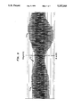
- FIG. 9 shows the detector signal output during a portion of a single pass of the detector electrodes under a wafer being polished.
- chem-mech polishing apparatus or lapping machine. Because chem-mech polishing apparatus and lapping machines are well known, this description is directed in particular to elements of chem-mech polishing apparatus forming part of or cooperating directly with the invention. It is to be understood, however, that other elements not specifically shown or described may take various forms known to persons of ordinary skill in the art.
- FIG. 2 an apparatus 50 for chem-mech polishing a semiconductor wafer 52 having metal lines, contact/via studs, and/or pads 54 is shown.
- a thick dielectric layer 56 comprising for example silicon dioxide, overlies the metal lines 54 and the remainder of surface 58 of semiconductor wafer 52.
- semiconductor wafer 52 may have been preprocessed and therefore already include layers of interleaved circuitry. For simplicity, those other features are not represented in FIG. 2.
- Apparatus 50 may comprise any commercially available chem-mech polishing apparatus, such as, a Strasbaugh 6CA single wafer polisher available from R. Howard Strasbaugh Inc. of Huntington Beach, Calif.
- Apparatus 50 includes a wafer carrier or holder 60 having a suitable means for securing wafer 52 thereto. As shown, wafer 52 is positioned between wafer carrier 60 and a polishing table 62. Wafer carrier 60 is mounted by suitable means above polishing table 62 for rotation about axis A 1 in a direction indicated by arrow 104.
- the polishing table 62 includes a conductive platen 64 and a polishing pad 66 having holes 68 formed therein. Conductive platen 64 is electrically grounded by suitable means. Furthermore, polishing table 62 rotates about axis A 2 in a direction indicated by arrow 106. A conductive polishing slurry 61 is provided also.
- a thickness monitoring/endpoint detection apparatus 40 comprises a conductive center electrode 70 and at least one conductive guard electrode 72 embedded within platen 64.
- Conductive center electrode 70 comprises an active electrode, to be discussed supra.
- the at least one guard electrode 72 is concentric with center electrode 70 and comprises a passive electrode, to be discussed supra, also. While only one guard electrode 72 is shown, more than one may be included.
- An insulator 74 comprising teflon, for example, electrically isolates electrodes 70 and 72 from one another and from conductive platen 64.
- the thickness monitoring/endpoint detection apparatus 40 of the present invention further comprises a signal generator means 80 having an output 80 out for providing an output signal having a frequency in the range of 500 to 50,000 hertz and an amplitude of less than one-half volt.
- Signal generating means 80 comprises any suitable means for providing the desired output signal.
- a voltage follower 82 having an input 82 in and an output 82 out , is electrically connected at the voltage follower input 82 in to the output 80 out of the signal generating means 80.
- the voltage follower output 82 out is electrically connected to the at least one guard electrode 72 by suitable means, such as a slip-ring assembly (not shown), for example. Voltage follower 82 prevents undesired loading of signal generating means 80.
- a current-to-voltage converter 84 having first and second inputs, 84 in1 and 84 in2 , respectively, and an output 84 out , is electrically connected to center electrode 70 by suitable means, such as a slip-ring assembly (not shown), for example.
- Second input 84 in2 is electrically connected to the output 80 out of signal generating means 80.
- Current-to-voltage converter 84 converts a current I 10 flowing through the center electrode 70 into a voltage signal at output 84 out when apparatus 40 is active.
- the gain current-to-voltage converter 84 is controlled by the value of feedback resistance R connected between input 84 in and output 84 out .
- a differential amplifier 86 having first and second inputs, 86 in1 and 86 in2 , respectively, is electrically connected at first input 86 in1 to the output 84 out of current-to-voltage converter 84. Second input 86 in2 of differential amplifier 86 is electrically connected to the output 80 out of signal generating means 80. Differential amplifier 86 further provides an output voltage on output 86 out , the output voltage being representative of the current I 10 flowing through center electrode 70. Differential amplifier 86 serves to subtract out that portion of the voltage signal contained in the output 84 out which is attributable to the signal generating means voltage.
- an analog-to-digital converter (ADC) 88 comprises any suitable ADC, having signal input channel 88 in , a trigger input channel 88 TRIG , and digital output 88 out .
- Input channel 88 in is electrically connected to differential amplifier 86 output 86 out , for receiving the voltage representative of the current I 10 flowing through center electrode 70.
- Trigger input 88 TRIG is electrically connected to a position detection device 90.
- Position detection device 90 can comprise any suitable means for providing a signal indicative of a preestablished positional relationship between the wafer carrier 60 (and thus the wafer 52 being polished) and the electrodes 70 and 72 (to be discussed further hereafter below with reference to a detection region).
- Control means 92 can comprise, for example, any suitable programmable computer, the control means 92 for receiving digital signals and converting the same into a cognizable form for use by an operator of the CMP apparatus or for automatic control purposes.
- control means 92 may include a display means for real-time display of thickness data during the polishing of wafer 52 by CMP apparatus 50.
- the thickness data is determined from a change in voltage during polishing from an initial voltage at the beginning of the polishing operation for a particular wafer. This change in voltage corresponds to a given thickness and is the parameter of importance.
- Detection region 100 is that region defined by the positional relationship between the wafer holder or carrier 60 and electrodes 70 and 72 in which electrodes 70 and 72 are positioned below wafer carrier 60 during polishing.
- Position detection device 90 is used to detect and indicate when electrodes 70 and 72 are within the detection region. More particularly, position detection device 90 can detect a desired portion 102 of detection region 100.
- Position detection device 90 preferably comprises any suitable sensing device for sensing position information. For instance, position information may include information which is coded on an outer edge portion of polishing table 62.
- position detection device 90 to output a trigger signal when electrodes 70 and 72 are within detection region 100 or at some desired position or positions within detection region 100, such as portion 102.
- Position encoders are well known in the art and thus not further described herein.
- position detection device 90 may comprise a position sensing switch and a time delay, such that upon detection of electrodes 70 and 72 attaining a prescribed position along their path of travel, an output signal is generated for a desired time. In this later instance, the desired time would correspond to an amount of travel of electrodes 70 and 72 along their path of travel as a function of the rotational speed of table 62.
- Wafer 52 comprising a 5" silicon wafer having a 2000 ⁇ thick aluminum dot pattern thereon and further covered with a 2 ⁇ m silicon dioxide layer, is mounted onto wafer holder 60 and then placed above polishing table 62.
- Conductive slurry 61 is then added.
- conductive slurry 61 comprises an oxide slurry, such as commercially available Cab-O-Sperse SC-1 slurry diluted 5:1 in deionized (DI) water. (Cab-O-Sperse is a registered trademark of Cabot Corporation.)
- the oxide slurry should be highly conductive for a wide range of dilutions to allow for good electrical contact between the wafer 52 and electrodes 70 and 72.
- Wafer holder 60 and polishing table 62 are then rotated in directions indicated by arrows 104 and 106, respectively.
- Typical holder 60 and table 62 speeds are (30 to 60) and 60 revolutions per minute (rpm), respectively.
- I 10 (t) is inversely related to the thickness d(t) of the polished dielectric 56 through the relationship:
- w is the frequency of the applied sinusoidal voltage signal
- ⁇ is the dielectric constant of the polished film
- A is the effective detector or electrode area
- V o is the amplitude of the applied sinusoidal voltage.
- Electrodes 70 and 72 Upon rotation of table 62, electrodes 70 and 72 traverse along a circular path 105, wherein three positions of electrodes 70 and 72 along path 105 are indicated by numerals 107 A , 107 B , and 107 C (FIG. 4). Electrodes 70 and 72 enter and exit detection region 100 as shown by positions 107 B and 107 C , respectively. While within the detection region, the electrical circuit formed between the grounded polishing table 62, the wafer 52 being polished, and the center electrode 70 is completed and a current I 10 passes through the film stack 56 and back into the grounded polishing table 62.
- the current I 10 consists of a sinusoidal pulse whose pulse width depends upon the time spent by the rotating wafer 52 over the electrodes 70 and 72, i.e., the detection region can be viewed in terms of time. For the 5" wafer located at a 6.5" radius from axis A 2 and a table rotating speed of 60 rpm, this time corresponds to approximately 100 Msec. This time will be longer for larger wafer sizes and reduced table speeds.
- the current pulse is converted to a voltage pulse using the current-to-voltage converter 84.
- the output of current-to-voltage converter 84 is then inputed through amplifier 86 to ADC 88.
- ADC 88 converts the voltage and provides a digital output signal to control means 92 upon receipt of a trigger signal on trigger input 88 TRIG .
- position detection device 90 provides a trigger signal when wafer 52 is within the detection region 100.
- Position detection device 90 can be controlled for providing a trigger signal for the entire detection region 100 or a portion 102 of detection region 100.
- position detection device 90 is controlled to trigger ADC 88 when the electrodes 70 and 72 pass under the center portion of wafer 52, corresponding to portion 102 of detection region 100.
- portion 102 of detection region 100 corresponds to a 1 to 10 Msec "snap-shot" of the output voltage V 2 which is digitized, and still further corresponding to 20 to 200 voltage signal wave oscillations.
- the trigger location and time window 102 are selected so as to allow a voltage pulse envelope comprising voltage signal wave oscillations to reach its full amplitude, thereby avoiding initial and final transients attributable to the edges of the wafer carrier 60 and wafer 52 as electrodes 70 and 72 enter and exit the detection region 100.
- the ADC digitized voltage signal is then sent to control means 92 for monitoring and processing, whereby voltage data, corresponding to dielectric layer 56 thickness, is collected as the wafer 52 is being polished.
- the CMP apparatus Upon attaining a desired thickness, the CMP apparatus is turned off and polishing is stopped.
- FIG. 5 is representative of an ADC digital output voltage vs. time corresponding to reduced oxide thickness.
- Such a graph is produced by control means 92 by suitable well known programming of control means 92, using commercially available software, for example, QBASIC, as sold by Microsoft Corporation of Redmond, Wash.
- a change in output voltage corresponding to 0.25 V corresponds to a removal of 1.36 ⁇ m of SiO 2 .
- the oxide film 56 thickness was measured before and after polishing using a Prometrix 500 available from Prometrix Corporation of Santa Clara, Calif.
- the data points in the FIG. 5 were averaged over 3 revolutions (i.e., running average), thereby improving the signal-to-noise ratio.
- the noise component of the data which was smoothed out considerably by this averaging procedure, is spike-like in nature.
- the remaining ripple ( ⁇ 0.022 V) still seen in the signal most probably results from slurry shunt current which was not totally eliminated by the guard electrode.
- the solid line drawn through the data is obtained by a well known polynomial least square fit routine performed by control means 92.
- Curve 108 is representative of the output of CMP thickness monitoring/endpoint detection apparatus 40 upon the polishing of an SiO 2 film layer upon a Si wafer having zero percent metal coverage. Initial thickness of the SiO 2 film layer was 2.0 ⁇ m and at time t 6 , the film layer thickness was 0.78 ⁇ m.
- Curve 110 is representative of the output of CMP thickness monitoring/endpoint detection apparatus 40 upon an aluminum layer (100% metal coverage) upon a Si wafer.
- Initial thickness of the SiO 2 film layer was 2.0 ⁇ m and at time t 6 , the SiO 2 film layer thickness was 0.85 ⁇ m.
- Polishing parameters used for these latter two examples include a polishing table speed of 62 rpm, wafer holder speed of 60 rpm, and a polishing slurry of SC-1 diluted 5:1 in deionized water.
- the output from SiO 2 /Al dots/Si for a similar change in thickness is intermediate between the two curves 108 and 110. This reduction of signal for a given change in thickness (i.e., sensitivity) is attributed to a larger contribution of the Si wafer impedance to the measurement than in the absence of any metalization.
- a typical output signal is schematically represented which includes voltage pulse envelopes or wavepackets 120 and 122, respectively.
- Voltage pulse envelopes or wavepackets 120 and 122 are voltage signal envelopes obtained or produced at amplifier output 86 out for multiple passes of the detector electrodes 70 and 72 under wafer 52.
- the voltage signal envelopes or wavepackets 120 and 122 are separated in time by a time distance T between the wavepackets corresponding to the rotation period of the polishing table 62.
- Each wavepacket is characterized by five (5) different regions: region A is a pre-measurement signal region, region B is a rising transient signal region, region C is a steady state signal region, region D is a fall off transient region, and lastly, region E is a post measurement signal region.
- the magnitude of the pre- and post-measurement signals contained in regions A and E, respectively, have been found to be independent with time and therefore do not contain information about the dielectric film layer thickness of the wafer being polished.
- the signals contained in regions A and E are attributed to a current flowing through a pile-up or "pool" 114 of slurry which exists around the wafer carrier 60 (see FIGS. 8a and 8b). In other words, as electrodes 70 and 72 approach wafer carrier 60 along path 105, the electrodes enter the "pool" 114 of slurry 61.
- the electrodes 70 and 72 clear the slurry "pool” 114 upon movement along path 105 when the electrodes move completely under wafer carrier 60, at which time, only a very thin layer of slurry is expected between the wafer and the electrodes.
- Regions B and D as shown in FIG. 7 correspond to the electrodes entering and leaving the area under the outer edge of wafer 52.
- Region C corresponds to the electrodes being completely under wafer 52 along path 105. It is within region C that the desired portion 102 of detection region 100 (FIG. 4) is selected.
- FIG. 8a shows a top view of wafer carrier 60 and electrodes 70 and 72 in relation to each other during one instant of a polishing operation.
- FIG. 8b is a sectional view of the wafer carrier 60 during polishing.
- a pressure P is exerted via the wafer carrier 60 upon polishing pad 66 causing a slight deformation therein. Creation of the slurry pool 114 is due in part to the deformation of pad 66 caused by contact with wafer carrier 60.
- dielectric layer thickness detection is facilitated by taking a "snap-shot" of voltage signal information when electrodes 70 and 72 pass under the center of wafer 52, i.e., around the middle of region C as shown in FIG. 7. In this manner, undesired transients as well as pre- and post-measurement signals are advantageously avoided.
- region C different portions thereof correspond to thickness data from different locations across wafer 52. That is, the magnitude of the voltage signal is proportional to the dielectric layer thickness across wafer 52.
- the digitized voltage amplitudes across the wavepacket in region C are sent to control means 92 for quantitative analysis.
- the mean thickness and standard deviation across the desired area of region C is calculated in-situ and a decision regarding whether or not to proceed with the polishing operation is made. Determination of standard deviation and mean values can be by suitable methods known in the art.
- FIG. 9 shows a signal output representative of non-uniform polishing conditions wherein the thickness of the dielectric layer corresponding to C2 is smaller than at points corresponding to C1 and C3. Criteria, suitable for a particular polishing operation, can be established as appropriate for an acceptable in-situ non-uniformity set point, i.e., the point at which polishing is interrupted or terminated due to excessive in-situ non-uniform polishing.
- CMP thickness monitoring/endpoint detection apparatus which provides fast response, real-time, low voltage operation. In-situ CMP removal uniformity monitoring and detection is provided also. Furthermore, the CMP thickness monitoring/endpoint detection apparatus of the present invention is suitable for use over a range of polishing table speeds from below 20 rpm to speeds well in excess of 20 rpm.
Abstract
An in-situ thickness monitoring/endpoint detection method and apparatus for chemical-mechanical polishing (CMP) of a dielectric layer on a top surface of a semiconductor wafer is disclosed. The apparatus comprises center and guard electrodes and associated electronic circuitry, including a high frequency, low voltage signal generating means, for converting a current which is inversely proportional to the dielectric layer thickness into a corresponding analog voltage. A position detection device triggers an analog-to-digital converter to convert the analog voltage into a digital signal while the wafer is located within a detection region as the wafer is being polished. A control means gathers the digital signals corresponding to the thickness data for processing and CMP device control.
Description
1. Field of the Invention
This invention relates to a method and apparatus for use determining a planarization endpoint, during a chemical-mechanical polishing process, of a semiconductor wafer.
2. Discussion of the Related Art
In VLSI wiring technology, connecting metal lines are formed over a substrate containing device circuitry. These metal lines serve to electrically interconnect the discrete devices. These metal connecting lines are further insulated from the next interconnection level by thin films of insulating material formed by, for example, chemical vapor deposition (CVD) of oxide. In order to interconnect metal lines of different interconnection levels, holes are formed in the insulating layers to provide electrical access therebetween.
In such wiring processes, it is desirable that the insulating layers have a smooth surface topography, because rough surfaces cause fabrication problems. More specifically, it is difficult to image and pattern layers applied to rough surfaces, and this difficulty increases as the number of layers increases.
Recently chemical-mechanical (chem-mech) polishing (CMP) has been developed for providing smooth insulator topographies. CMP includes the use of polishing machines and other chemical-mechanical planarization processes. In these processes, it is important to remove a sufficient amount of material to provide a smooth surface, without removing an excessive amount of underlying materials. Thus, a precise etch endpoint detection technique is needed.
Presently, there are various types of lapping machines for reducing the thickness of semiconductor wafers. In general, these lapping machines include top and bottom lapping plates, between which the wafers are positioned. The two lapping plates are then moved relative to each other, and a slurry, consisting of an abrasive solution with or without an etching reagent, is fed between the plates to grind and flush away ground wafer particles. While lapping is typically associated with bulk removal of material from a wafer surface, chemical-mechanical polishing refers to polishing of thin films rather than bare wafers. In chemical-mechanical polishing, the slurry is fed between the lapping or polishing plates to polish and flush away the material removed. A chemical-mechanical polishing machine can include a single rotating polishing plate and a smaller diameter rotating wafer carrier to which a wafer (or wafers) is (are) mounted. The wafer carrier is held above the polishing plate, either in a stationary fixed position or oscillating back and forth in a predetermined path, while both polishing plate and wafer carrier are rotated about their respective center axes. A slurry, consisting of an abrasive suspension with or without an etching reagent, is fed onto the polishing plate during polishing of the wafer.
FIG. 1 shows an example of the formation of an interlevel contact stud 10 (FIG. 1(d)) between a first level metalization 12 and a second level metalization (not shown) in a high performance VLSI circuit 16. An interlevel dielectric 18 is deposited so as to conformally coat a lower level pattern 12 and fill gaps 20 between metallic lines 12. A rough surface 22 results which needs to be planarized prior to the next photoresist image being formed. Planarization is achieved upon polishing back a desired amount using CMP as indicated by the dotted line 24 in FIG. 1(b). The planarization is a consequence of using a polishing pad of an appropriate stiffness which transmits a higher pressure to the more elevated areas, thereby removing them more efficiently. Thin SiO2 and SiNx "cap" layers, 23a and 23b, respectively, are then deposited. Following via formation by reactive ion etching, a metalization layer 26 is blanket deposited (FIG. 1(c)). The metalization layer 26 is selectively polished back to produce planar metal studs 10 as shown in FIG. 1(d). A persistent difficulty in this process is the inability to determine when the required thickness 24 or endpoint has been reached during the first dielectric polishing step. One method of determining the required thickness or CMP endpoint is by using estimated CMP rates and time. CMP rates vary considerably with time, however, due to changes in polishing pad characteristics. Frequent stops are required in the fabrication process for ex-situ thickness measurements. This method is extremely time consuming and highly undesirable since operators must inspect each wafer after polish. Process throughput is thereby reduced and product yields are lowered. A more precise CMP endpoint detection method and apparatus is desired. In addition., while an endpoint for the second polishing step (metalization layer polish) can be achieved by inspection and observation of the blanket to patterned layer transition, automated endpoint detection would also be highly desirable.
An in-situ CMP endpoint determination method and apparatus is shown in U.S. Pat. No. 5,081,421, issued Jan. 14, 1992 and assigned to AT&T Bell Laboratories. In the '421 patent, the in-situ endpoint determination is based on a measurement of a voltage required to maintain a fixed current flow through a structure under polish. The voltage decreases linearly with the thickness of the dielectric. A disadvantage of the '421 patent endpoint CMP detector is its inability to provide endpoint measurement for polishing table speeds in excess of 20 to 25 rpm's for 5" wafers, such as 60 rpm, which are typical in many polishing applications wherein the maximum rpm is a function of wafer size. Another disadvantage of the '421 device is that it requires relatively high voltage operation (approximately 3 to 5 volts) which is incompatible for use in VLSI fabrication of low voltage (i.e., less than one-half volt) silicon junction devices.
In addition to the above-noted characteristics of CMP, removal uniformity can change during polishing of a wafer as a result of changes in pad and wafer carrier conditions. Detection of abnormal removal uniformity or spurious changes therein is therefore highly desirable, i.e., a method and apparatus for in-situ detection and monitoring of removal uniformity.
Thus, there remains a continuing need in the semiconductor fabrication art for an apparatus and method which accurately and efficiently detects and monitors polishing characteristics of a chemical-mechanical planarization process. A fast response time, low voltage device is highly desired.
An object of the present invention is to provide a low voltage CMP thickness monitor/endpoint detection method and apparatus.
Another object of the present invention is to provide a method and apparatus for CMP thickness monitoring/endpoint detection operable over a wide range of polishing table speeds such as low polishing table speeds of 20-25 rpm to polishing table speeds in excess of 20-25 rpm.
Yet another object of the present invention is to provide a method and apparatus for in-situ removal uniformity detection.
According to the invention, an in-situ thickness monitoring/endpoint detection method and apparatus for monitoring the thickness of a dielectric film layer on a surface of a workpiece during polishing in a polishing machine, the polishing machine having an electrically grounded rotatable polishing table and further being provided with a conductive slurry, comprises the following: A center electrode is embedded within and electrically isolated from the polishing table of the polishing machine, wherein the center electrode electrically contacts the workpiece via the conductive polishing slurry. At least one guard electrode is embedded within and electrically isolated from the polishing table of the polishing machine and from the center electrode, wherein the at least one guard electrode is concentric with and surrounding the center electrode and further wherein the at least one guard electrode electrically contacts the workpiece via the conductive polishing slurry. A sinusoidal voltage signal generating means provides an output signal having a frequency in the range of 500 to 50,000 hertz and an amplitude of less than one-half volt. A voltage follower, having an input and an output, is electrically connected at its input to the output of the signal generating means and further connected at its output to the at least one guard electrode. A current-to-voltage converter, having first and second inputs and an output, is electrically connected at its first input to the center electrode and at its second input to the output of the signal generating means, wherein the current-to-voltage converter converts a current flowing through the center electrode into a voltage signal. A differential amplifier, having first and second inputs, is electrically connected at its first input to the output of the current-to-voltage converter and at its second input to the output of the signal generating means. The differential amplifier further comprises an output for providing an output voltage representative of the current flowing through the center electrode, whereby the amplitude of the differential amplifier output voltage is inversely proportional to the thickness of the film layer of the workpiece being polished when the workpiece being polished is within a detection region.
FIGS. 1(a)-(d) are schematic representations of VLSI wiring fabrication, including a thick dielectric layer upon a semiconductor wafer;
FIG. 2 is a schematic representation of the apparatus of the present invention;
FIG. 3 is a top view of center and guard electrodes, according to the present invention, embedded within the polishing table;
FIG. 4 is a schematic top view representation of the detection region for taking measurements of the dielectric layer thickness during each revolution of the polishing table;
FIG. 5 shows a graph of time versus voltage for an SiO2 /Al dots/Si wafer;
FIG. 6 shows a graph of time versus voltage for SiO2 /Si and SiO2 /Al/Si wafers;
FIG. 7 shows a schematic representation of the detector signal;
FIGS. 8a and 8b show top and side views, respectively, of the wafer carrier and the detector electrodes at a point in time during polishing of a wafer; and
FIG. 9 shows the detector signal output during a portion of a single pass of the detector electrodes under a wafer being polished.
The invention is disclosed in connection with a chem-mech polishing apparatus or lapping machine. Because chem-mech polishing apparatus and lapping machines are well known, this description is directed in particular to elements of chem-mech polishing apparatus forming part of or cooperating directly with the invention. It is to be understood, however, that other elements not specifically shown or described may take various forms known to persons of ordinary skill in the art.
Referring now to FIG. 2, an apparatus 50 for chem-mech polishing a semiconductor wafer 52 having metal lines, contact/via studs, and/or pads 54 is shown. A thick dielectric layer 56, comprising for example silicon dioxide, overlies the metal lines 54 and the remainder of surface 58 of semiconductor wafer 52. It should be noted that semiconductor wafer 52 may have been preprocessed and therefore already include layers of interleaved circuitry. For simplicity, those other features are not represented in FIG. 2.
Referring now to FIGS. 2 and 3, according to the present invention, a thickness monitoring/endpoint detection apparatus 40 comprises a conductive center electrode 70 and at least one conductive guard electrode 72 embedded within platen 64. Conductive center electrode 70 comprises an active electrode, to be discussed supra. The at least one guard electrode 72 is concentric with center electrode 70 and comprises a passive electrode, to be discussed supra, also. While only one guard electrode 72 is shown, more than one may be included. An insulator 74, comprising teflon, for example, electrically isolates electrodes 70 and 72 from one another and from conductive platen 64.
Referring again to FIG. 2, the thickness monitoring/endpoint detection apparatus 40 of the present invention further comprises a signal generator means 80 having an output 80out for providing an output signal having a frequency in the range of 500 to 50,000 hertz and an amplitude of less than one-half volt. Signal generating means 80 comprises any suitable means for providing the desired output signal. A voltage follower 82, having an input 82in and an output 82out, is electrically connected at the voltage follower input 82in to the output 80out of the signal generating means 80. The voltage follower output 82out is electrically connected to the at least one guard electrode 72 by suitable means, such as a slip-ring assembly (not shown), for example. Voltage follower 82 prevents undesired loading of signal generating means 80.
A current-to-voltage converter 84 having first and second inputs, 84in1 and 84in2, respectively, and an output 84out, is electrically connected to center electrode 70 by suitable means, such as a slip-ring assembly (not shown), for example. Second input 84in2 is electrically connected to the output 80out of signal generating means 80. Current-to-voltage converter 84 converts a current I10 flowing through the center electrode 70 into a voltage signal at output 84out when apparatus 40 is active. The gain current-to-voltage converter 84 is controlled by the value of feedback resistance R connected between input 84in and output 84out.
A differential amplifier 86, having first and second inputs, 86in1 and 86in2, respectively, is electrically connected at first input 86in1 to the output 84out of current-to-voltage converter 84. Second input 86in2 of differential amplifier 86 is electrically connected to the output 80out of signal generating means 80. Differential amplifier 86 further provides an output voltage on output 86out, the output voltage being representative of the current I10 flowing through center electrode 70. Differential amplifier 86 serves to subtract out that portion of the voltage signal contained in the output 84out which is attributable to the signal generating means voltage.
Referring still to FIG. 2, an analog-to-digital converter (ADC) 88 comprises any suitable ADC, having signal input channel 88in, a trigger input channel 88TRIG, and digital output 88out. Input channel 88in is electrically connected to differential amplifier 86 output 86out, for receiving the voltage representative of the current I10 flowing through center electrode 70. Trigger input 88TRIG is electrically connected to a position detection device 90. Position detection device 90 can comprise any suitable means for providing a signal indicative of a preestablished positional relationship between the wafer carrier 60 (and thus the wafer 52 being polished) and the electrodes 70 and 72 (to be discussed further hereafter below with reference to a detection region). A trigger signal received by trigger input 88TRIG instructs ADC 88 to convert the analog voltage appearing at input 88in to a digital signal on output 88out. Output 88out is electrically connected to input 92in of control means 92. Control means 92 can comprise, for example, any suitable programmable computer, the control means 92 for receiving digital signals and converting the same into a cognizable form for use by an operator of the CMP apparatus or for automatic control purposes. For example, control means 92 may include a display means for real-time display of thickness data during the polishing of wafer 52 by CMP apparatus 50. Preferably, the thickness data is determined from a change in voltage during polishing from an initial voltage at the beginning of the polishing operation for a particular wafer. This change in voltage corresponds to a given thickness and is the parameter of importance.
Turning now to FIG. 4, a schematic top view representation of the above-mentioned detection region 100 is shown. Detection region 100 is that region defined by the positional relationship between the wafer holder or carrier 60 and electrodes 70 and 72 in which electrodes 70 and 72 are positioned below wafer carrier 60 during polishing. Position detection device 90 is used to detect and indicate when electrodes 70 and 72 are within the detection region. More particularly, position detection device 90 can detect a desired portion 102 of detection region 100. Position detection device 90 preferably comprises any suitable sensing device for sensing position information. For instance, position information may include information which is coded on an outer edge portion of polishing table 62. In other words, the position information encoded on the table 62 enables position detection device 90 to output a trigger signal when electrodes 70 and 72 are within detection region 100 or at some desired position or positions within detection region 100, such as portion 102. Position encoders are well known in the art and thus not further described herein. Alternatively, position detection device 90 may comprise a position sensing switch and a time delay, such that upon detection of electrodes 70 and 72 attaining a prescribed position along their path of travel, an output signal is generated for a desired time. In this later instance, the desired time would correspond to an amount of travel of electrodes 70 and 72 along their path of travel as a function of the rotational speed of table 62.
Operation of the CMP thickness monitoring/endpoint detection apparatus 40 of the present invention will be discussed using the following example.
From the capacitive nature of this system, the displacement current, I10, and the associated output voltage, V2, increase with time. I10 (t) is inversely related to the thickness d(t) of the polished dielectric 56 through the relationship:
I.sub.10 (t)=[wεA/d(t)]V.sub.o cos wt
where
w is the frequency of the applied sinusoidal voltage signal;
ε is the dielectric constant of the polished film;
A is the effective detector or electrode area; and
Vo is the amplitude of the applied sinusoidal voltage.
Upon rotation of table 62, electrodes 70 and 72 traverse along a circular path 105, wherein three positions of electrodes 70 and 72 along path 105 are indicated by numerals 107A, 107B, and 107C (FIG. 4). Electrodes 70 and 72 enter and exit detection region 100 as shown by positions 107B and 107C, respectively. While within the detection region, the electrical circuit formed between the grounded polishing table 62, the wafer 52 being polished, and the center electrode 70 is completed and a current I10 passes through the film stack 56 and back into the grounded polishing table 62. The current I10 consists of a sinusoidal pulse whose pulse width depends upon the time spent by the rotating wafer 52 over the electrodes 70 and 72, i.e., the detection region can be viewed in terms of time. For the 5" wafer located at a 6.5" radius from axis A2 and a table rotating speed of 60 rpm, this time corresponds to approximately 100 Msec. This time will be longer for larger wafer sizes and reduced table speeds. The current pulse is converted to a voltage pulse using the current-to-voltage converter 84. The output of current-to-voltage converter 84 is then inputed through amplifier 86 to ADC 88. ADC 88 converts the voltage and provides a digital output signal to control means 92 upon receipt of a trigger signal on trigger input 88TRIG. AS previously discussed, position detection device 90 provides a trigger signal when wafer 52 is within the detection region 100. Position detection device 90 can be controlled for providing a trigger signal for the entire detection region 100 or a portion 102 of detection region 100. Preferably, position detection device 90 is controlled to trigger ADC 88 when the electrodes 70 and 72 pass under the center portion of wafer 52, corresponding to portion 102 of detection region 100. For instance, for a 20 Khz sinusoidal voltage signal being output by signal generator 80, portion 102 of detection region 100 corresponds to a 1 to 10 Msec "snap-shot" of the output voltage V2 which is digitized, and still further corresponding to 20 to 200 voltage signal wave oscillations. By selectively choosing the start of and the length of time sampled, transients in the voltage signal V2 which are attributed to the electrodes 70 and 72 passing under the edge portions of wafer holder 62, are advantageously avoided. The trigger location and time window 102 are selected so as to allow a voltage pulse envelope comprising voltage signal wave oscillations to reach its full amplitude, thereby avoiding initial and final transients attributable to the edges of the wafer carrier 60 and wafer 52 as electrodes 70 and 72 enter and exit the detection region 100. The ADC digitized voltage signal is then sent to control means 92 for monitoring and processing, whereby voltage data, corresponding to dielectric layer 56 thickness, is collected as the wafer 52 is being polished. Upon attaining a desired thickness, the CMP apparatus is turned off and polishing is stopped.
FIG. 5 is representative of an ADC digital output voltage vs. time corresponding to reduced oxide thickness. Such a graph is produced by control means 92 by suitable well known programming of control means 92, using commercially available software, for example, QBASIC, as sold by Microsoft Corporation of Redmond, Wash. In the example shown, a change in output voltage corresponding to 0.25 V corresponds to a removal of 1.36 μm of SiO2. To verify this result, the oxide film 56 thickness was measured before and after polishing using a Prometrix 500 available from Prometrix Corporation of Santa Clara, Calif. The data points in the FIG. 5 were averaged over 3 revolutions (i.e., running average), thereby improving the signal-to-noise ratio. The noise component of the data, which was smoothed out considerably by this averaging procedure, is spike-like in nature. The remaining ripple (±0.022 V) still seen in the signal most probably results from slurry shunt current which was not totally eliminated by the guard electrode. The solid line drawn through the data is obtained by a well known polynomial least square fit routine performed by control means 92.
The effects of polishing wafers, having various degrees of metal pattern coverage under an oxide layer, on the ADC 88 digital voltage output for oxide removals of approximately 1.2 μm from an initial 2.0 μm thickness are shown in FIG. 6. Curve 108 is representative of the output of CMP thickness monitoring/endpoint detection apparatus 40 upon the polishing of an SiO2 film layer upon a Si wafer having zero percent metal coverage. Initial thickness of the SiO2 film layer was 2.0 μm and at time t6, the film layer thickness was 0.78 μm. Curve 110 is representative of the output of CMP thickness monitoring/endpoint detection apparatus 40 upon an aluminum layer (100% metal coverage) upon a Si wafer. Initial thickness of the SiO2 film layer was 2.0 μm and at time t6, the SiO2 film layer thickness was 0.85 μm. Polishing parameters used for these latter two examples include a polishing table speed of 62 rpm, wafer holder speed of 60 rpm, and a polishing slurry of SC-1 diluted 5:1 in deionized water. The output from SiO2 /Al dots/Si for a similar change in thickness is intermediate between the two curves 108 and 110. This reduction of signal for a given change in thickness (i.e., sensitivity) is attributed to a larger contribution of the Si wafer impedance to the measurement than in the absence of any metalization. Also, these results suggest a procedure whereby the detector will be calibrated for every pattern and level to be polished. Once this calibration is performed a given change in voltage will correspond to the change in thickness for the given VLSI structure. However, as previously mentioned, it's the change in voltages for a given change in thickness which is the parameter of importance. It is noted that since the voltage monitored is the change between the initial and final voltages, changes in the initial absolute voltage are not expected to affect the measurements.
Referring now to FIG. 7, the in-situ removal monitoring aspect of the present invention will be explained. A typical output signal is schematically represented which includes voltage pulse envelopes or wavepackets 120 and 122, respectively. Voltage pulse envelopes or wavepackets 120 and 122 are voltage signal envelopes obtained or produced at amplifier output 86out for multiple passes of the detector electrodes 70 and 72 under wafer 52. The voltage signal envelopes or wavepackets 120 and 122 are separated in time by a time distance T between the wavepackets corresponding to the rotation period of the polishing table 62. Each wavepacket is characterized by five (5) different regions: region A is a pre-measurement signal region, region B is a rising transient signal region, region C is a steady state signal region, region D is a fall off transient region, and lastly, region E is a post measurement signal region.
The magnitude of the pre- and post-measurement signals contained in regions A and E, respectively, have been found to be independent with time and therefore do not contain information about the dielectric film layer thickness of the wafer being polished. The signals contained in regions A and E are attributed to a current flowing through a pile-up or "pool" 114 of slurry which exists around the wafer carrier 60 (see FIGS. 8a and 8b). In other words, as electrodes 70 and 72 approach wafer carrier 60 along path 105, the electrodes enter the "pool" 114 of slurry 61. While the electrodes 70 and 72 are within the "pool" 114, the guarding scheme provided via guard electrode 72 and associated circuitry become ineffective and the center electrode 70 is essentially shorted to ground as illustrated by current flow lines 115 of FIG. 8a. The electrodes 70 and 72 clear the slurry "pool" 114 upon movement along path 105 when the electrodes move completely under wafer carrier 60, at which time, only a very thin layer of slurry is expected between the wafer and the electrodes. Regions B and D as shown in FIG. 7 correspond to the electrodes entering and leaving the area under the outer edge of wafer 52. Region C corresponds to the electrodes being completely under wafer 52 along path 105. It is within region C that the desired portion 102 of detection region 100 (FIG. 4) is selected. FIG. 8a shows a top view of wafer carrier 60 and electrodes 70 and 72 in relation to each other during one instant of a polishing operation. FIG. 8b is a sectional view of the wafer carrier 60 during polishing. A pressure P is exerted via the wafer carrier 60 upon polishing pad 66 causing a slight deformation therein. Creation of the slurry pool 114 is due in part to the deformation of pad 66 caused by contact with wafer carrier 60.
As indicated previously, dielectric layer thickness detection is facilitated by taking a "snap-shot" of voltage signal information when electrodes 70 and 72 pass under the center of wafer 52, i.e., around the middle of region C as shown in FIG. 7. In this manner, undesired transients as well as pre- and post-measurement signals are advantageously avoided.
With respect to region C, different portions thereof correspond to thickness data from different locations across wafer 52. That is, the magnitude of the voltage signal is proportional to the dielectric layer thickness across wafer 52. Thus, by inspecting wavepacket 120 or any subsequent wavepacket, information about the removal uniformity can be obtained in-situ. In particular, the digitized voltage amplitudes across the wavepacket in region C are sent to control means 92 for quantitative analysis. The mean thickness and standard deviation across the desired area of region C is calculated in-situ and a decision regarding whether or not to proceed with the polishing operation is made. Determination of standard deviation and mean values can be by suitable methods known in the art. FIG. 9 shows a signal output representative of non-uniform polishing conditions wherein the thickness of the dielectric layer corresponding to C2 is smaller than at points corresponding to C1 and C3. Criteria, suitable for a particular polishing operation, can be established as appropriate for an acceptable in-situ non-uniformity set point, i.e., the point at which polishing is interrupted or terminated due to excessive in-situ non-uniform polishing.
There is thus provided a CMP thickness monitoring/endpoint detection apparatus which provides fast response, real-time, low voltage operation. In-situ CMP removal uniformity monitoring and detection is provided also. Furthermore, the CMP thickness monitoring/endpoint detection apparatus of the present invention is suitable for use over a range of polishing table speeds from below 20 rpm to speeds well in excess of 20 rpm.
While the invention has been particularly shown and described with reference to the preferred embodiment thereof, it will be understood by those skilled in the art that various changes in form and detail may be made without departing from the spirit and scope of the invention.
Claims (21)
1. An apparatus for monitoring the thickness of a dielectric film layer on a surface of a workpiece during polishing in a polishing machine, the polishing machine having an electrically grounded rotatable polishing table and further being provided with a conductive polishing slurry, said apparatus comprising:
a) a center electrode embedded within and electrically isolated from the polishing table of the polishing machine, said center electrode electrically contacting the workpiece via the conductive polishing slurry;
b) at least one guard electrode embedded within and electrically isolated from the polishing table of the polishing machine, said guard electrode being concentric with and surrounding said center electrode and further electrically contacting the workpiece via the conductive polishing slurry;
c) means for generating a sinusoidal voltage signal, said signal generating means providing an output signal on an output thereof, the output signal having a frequency in the range of 500 to 50,000 hertz and an amplitude of less than one-half volt;
d) a voltage follower having an input and an output, the voltage follower input being electrically connected to the output of said signal generating means and the voltage follower output being electrically connected to said guard electrode;
e) a current-to-voltage converter having first and second inputs and an output, the first input being electrically connected to said center electrode and the second input being electrically connected to the output of said signal generating means, said current-to-voltage converter for converting a current passing through the center electrode into a voltage signal; and
f) a differential amplifier having first and second inputs, the first input being electrically connected to the output of said current-to-voltage converter and the second input being electrically connected to the output of said signal generating means, said differential amplifier further having an output for providing an output voltage representative of the current passing through said center electrode, whereby the amplitude of the differential amplifier output voltage is inversely proportional to the thickness of the film layer of the workpiece being polished during movement of said center electrode and said at least one guard electrode through a detection region.
2. The apparatus of claim 1, further comprising
g) an analog-to-digital converter means for converting the differential amplifier output voltage into a digital signal;
h) means for triggering said analog-to-digital converter to convert the differential amplifier output voltage into digital signals as the workpiece is being polished, said triggering means triggering said analog-to-digital converter when said center electrode and said at least one guard electrode are within a prescribed portion of the detection region; and
i) means for converting said digital signals into thickness data values corresponding to the thickness of the polished dielectric film layer.
3. The apparatus of claim 2, further wherein the prescribed portion of the detection region comprises a portion of the detection region characterized by said center electrode and said at least one guard electrode being positioned below a center portion of the workpiece during polishing.
4. The apparatus of claim 2, further wherein said digital signal converting means further comprises a means for averaging the thickness data values.
5. The apparatus of claim 4, wherein said digital signal converting means comprises a computer, the computer further having a display for displaying the averaged thickness data values in real-time.
6. The apparatus of claim 4, further wherein the prescribed portion of the detection region comprises a portion of the detection region characterized by said center electrode and said at least one guard electrode being positioned below a center portion of the workpiece during polishing.
7. The apparatus of claim 2, further wherein said digital signal converting means comprises a means for computing a mean thickness value and a standard deviation from thickness data values generated during each individual pass of said center electrode and said at least one guard electrode through the detection region.
8. The apparatus of claim 7, wherein said digital signal converting means comprises a computer, the computer further having a display for displaying the mean
thickness value and the standard deviation in real-time.
9. The apparatus of claim 8, further wherein the prescribed portion of the detection region comprises a portion of the detection region characterized by said center electrode and said at least one guard electrode being positioned below a center portion of the workpiece during polishing.
10. The apparatus of claim 7, wherein said digital signal converting means still further comprises a means for comparing the mean thickness value and the standard deviation to a prescribed set-point thickness value and standard deviation, said comparing means further providing an indication when the set-point thickness value and standard deviation are exceeded by the mean thickness value and standard deviation, the indication being representative of polishing removal non-uniformity.
11. The apparatus of claim 10, further wherein the prescribed portion of the detection region comprises a portion of the detection region characterized by said center electrode and said at least one guard electrode being positioned below a center portion of the workpiece during polishing.
12. The apparatus of claim 10, wherein said digital signal converting means comprises a computer, the computer further having a display for displaying the mean thickness value and the standard deviation and further for displaying the indication of polishing removal non-uniformity in real-time.
13. The apparatus of claim 12, further wherein the prescribed portion of the detection region comprises a portion of the detection region characterized by said center electrode and said at least one guard electrode being positioned below a center portion of the workpiece during polishing.
14. A polishing apparatus having real-time in-situ thickness monitoring and being especially well suited for reducing the thickness of a dielectric film layer on a surface of a workpiece during polishing with a conductive polishing slurry, said polishing apparatus comprising:
a) an electrically grounded rotatable polishing table, said polishing table receiving the conductive polishing slurry thereon;
b) means for holding the workpiece above and in pressure contact with said polishing table, the surface of the workpiece to be polished being in contact with said polishing table;
c) a center electrode embedded within and electrically isolated from said polishing table, said center electrode electrically contacting the workpiece via the conductive polishing slurry;
d) at least one guard electrode embedded within and electrically isolated from said polishing table, said guard electrode being concentric with and surrounding said center electrode and further electrically contacting the workpiece via the conductive polishing slurry;
e) means for generating a sinusoidal voltage signal, said signal generating means providing an output signal on an output thereof, the output signal having a frequency in the range of 500 to 50,000 hertz and an amplitude of less than one-half volt.;
f) a voltage follower having an input and an output, the voltage follower input being electrically connected to the output of said signal generating means and the voltage follower output being electrically connected to said guard electrode;
g) a current-to-voltage converter having first and second inputs and an output, the first input being electrically connected to said center electrode and the second input being electrically connected to the output of said signal generating means, said current-to-voltage converter for converting a current passing through the center electrode into a voltage signal;
h) a differential amplifier having first and second inputs, the first input being electrically connected to the output of said current-to-voltage converter and the second input being electrically connected to the output of said signal generating means, said differential amplifier further having an output for providing an output voltage representative of the current passing through said center electrode, whereby the amplitude of the differential amplifier output voltage is inversely proportional to the thickness of the film layer of the workpiece being polished during movement of said center electrode and said at least one guard electrode through a detection region; and
i) means for controlling polishing of the workpiece in response to a monitored thickness of the film layer of the workpiece being polished, the monitored thickness being derived from the differential amplifier output voltage.
15. The apparatus of claim 14, wherein further comprising:
j) an analog-to-digital converter means for converting the differential amplifier output voltage into a digital signal;
k) means for triggering said analog-to-digital converter to convert the differential amplifier output voltage into digital signals as the workpiece is being polished, said triggering means triggering said analog-to-digital converter when said center electrode and said at least one guard electrode are within a prescribed portion of the detection region; and
l) means for converting said digital signals into thickness data values corresponding to the thickness of the polished dielectric film layer; and
further wherein the monitored thickness used by said control means is obtained from the thickness data values.
16. The apparatus of claim 15, further wherein the prescribed portion of the detection region comprises a portion of the detection region characterized by said center electrode and said at least one guard electrode being positioned below a center portion of the workpiece during polishing.
17. The apparatus of claim 15, further wherein said digital signal converting means further comprises a means for averaging the thickness data values.
18. The apparatus of claim 17, further wherein the prescribed portion of the detection region comprises a portion of the detection region characterized by said center electrode and said at least one guard electrode being positioned below a center portion of the workpiece during polishing.
19. The apparatus of claim 15, further wherein said digital signal converting means comprises a means for computing a mean thickness value and a standard deviation from thickness data values generated during each individual pass of said center electrode and said at least one guard electrode through the detection region.
20. The apparatus of claim 19, wherein said digital signal converting means still further comprises a means for comparing the mean thickness value and the standard deviation to a prescribed set-point thickness value and standard deviation, said comparing means further providing an indication when the set-point thickness value and standard deviation are exceeded by the mean thickness value and standard deviation, the indication being representative of polishing removal non-uniformity, and still further wherein said control means also controls the polishing operation in response to polishing removal non-uniformity.
21. The apparatus of claim 20, further wherein the prescribed portion of the detection region comprises a portion of the detection region characterized by said center electrode and said at least one guard electrode being positioned below a center portion of the workpiece during polishing.
Priority Applications (1)
| Application Number | Priority Date | Filing Date | Title |
|---|---|---|---|
| US08/075,628 US5337015A (en) | 1993-06-14 | 1993-06-14 | In-situ endpoint detection method and apparatus for chemical-mechanical polishing using low amplitude input voltage |
Applications Claiming Priority (1)
| Application Number | Priority Date | Filing Date | Title |
|---|---|---|---|
| US08/075,628 US5337015A (en) | 1993-06-14 | 1993-06-14 | In-situ endpoint detection method and apparatus for chemical-mechanical polishing using low amplitude input voltage |
Publications (1)
| Publication Number | Publication Date |
|---|---|
| US5337015A true US5337015A (en) | 1994-08-09 |
Family
ID=22127016
Family Applications (1)
| Application Number | Title | Priority Date | Filing Date |
|---|---|---|---|
| US08/075,628 Expired - Lifetime US5337015A (en) | 1993-06-14 | 1993-06-14 | In-situ endpoint detection method and apparatus for chemical-mechanical polishing using low amplitude input voltage |
Country Status (1)
| Country | Link |
|---|---|
| US (1) | US5337015A (en) |
Cited By (103)
| Publication number | Priority date | Publication date | Assignee | Title |
|---|---|---|---|---|
| US5433651A (en) * | 1993-12-22 | 1995-07-18 | International Business Machines Corporation | In-situ endpoint detection and process monitoring method and apparatus for chemical-mechanical polishing |
| US5492594A (en) * | 1994-09-26 | 1996-02-20 | International Business Machines Corp. | Chemical-mechanical polishing tool with end point measurement station |
| US5559428A (en) * | 1995-04-10 | 1996-09-24 | International Business Machines Corporation | In-situ monitoring of the change in thickness of films |
| US5595526A (en) * | 1994-11-30 | 1997-01-21 | Intel Corporation | Method and apparatus for endpoint detection in a chemical/mechanical process for polishing a substrate |
| US5597442A (en) * | 1995-10-16 | 1997-01-28 | Taiwan Semiconductor Manufacturing Company Ltd. | Chemical/mechanical planarization (CMP) endpoint method using measurement of polishing pad temperature |
| US5605760A (en) * | 1995-08-21 | 1997-02-25 | Rodel, Inc. | Polishing pads |
| US5607341A (en) | 1994-08-08 | 1997-03-04 | Leach; Michael A. | Method and structure for polishing a wafer during manufacture of integrated circuits |
| US5643050A (en) * | 1996-05-23 | 1997-07-01 | Industrial Technology Research Institute | Chemical/mechanical polish (CMP) thickness monitor |
| US5647952A (en) * | 1996-04-01 | 1997-07-15 | Industrial Technology Research Institute | Chemical/mechanical polish (CMP) endpoint method |
| US5660672A (en) * | 1995-04-10 | 1997-08-26 | International Business Machines Corporation | In-situ monitoring of conductive films on semiconductor wafers |
| US5667424A (en) * | 1996-09-25 | 1997-09-16 | Chartered Semiconductor Manufacturing Pte Ltd. | New chemical mechanical planarization (CMP) end point detection apparatus |
| US5667629A (en) * | 1996-06-21 | 1997-09-16 | Chartered Semiconductor Manufactuing Pte, Ltd. | Method and apparatus for determination of the end point in chemical mechanical polishing |
| US5723874A (en) * | 1996-06-24 | 1998-03-03 | International Business Machines Corporation | Dishing and erosion monitor structure for damascene metal processing |
| US5726581A (en) * | 1996-03-08 | 1998-03-10 | The United States Of America As Represented By The Administrator Of The National Aeronautics And Space Administration | 3-D capaciflector |
| US5733175A (en) | 1994-04-25 | 1998-03-31 | Leach; Michael A. | Polishing a workpiece using equal velocity at all points overlapping a polisher |
| US5838448A (en) * | 1997-03-11 | 1998-11-17 | Nikon Corporation | CMP variable angle in situ sensor |
| US5846882A (en) * | 1996-10-03 | 1998-12-08 | Applied Materials, Inc. | Endpoint detector for a chemical mechanical polishing system |
| WO1999004930A1 (en) * | 1997-07-25 | 1999-02-04 | Speedfam-Ipec Corporation | Wafer carrier for semiconductor wafer polishing machine |
| WO1999028702A1 (en) * | 1997-11-28 | 1999-06-10 | I.E.E. International Electronics & Engineering S.A.R.L. | Capacitive distance measurement using a non-ideal measuring electrode |
| US5957749A (en) * | 1995-05-23 | 1999-09-28 | Nova Measuring Instruments, Ltd. | Apparatus for optical inspection of wafers during polishing |
| US5964643A (en) * | 1995-03-28 | 1999-10-12 | Applied Materials, Inc. | Apparatus and method for in-situ monitoring of chemical mechanical polishing operations |
| LU90237B1 (en) * | 1998-04-30 | 1999-11-03 | Iee Sarl | Capacitive sensor, e.g. for passenger seat monitoring for control of motor vehicle airbag |
| US5985093A (en) * | 1996-05-28 | 1999-11-16 | Industrial Technology Research Institute | Chemical-mechanical polish (CMP) pad conditioner |
| US6007405A (en) * | 1998-07-17 | 1999-12-28 | Promos Technologies, Inc. | Method and apparatus for endpoint detection for chemical mechanical polishing using electrical lapping |
| US6015754A (en) * | 1996-12-25 | 2000-01-18 | Kabushiki Kaisha Toshiba | Chemical mechanical polishing apparatus and method |
| US6020264A (en) * | 1997-01-31 | 2000-02-01 | International Business Machines Corporation | Method and apparatus for in-line oxide thickness determination in chemical-mechanical polishing |
| US6060370A (en) * | 1998-06-16 | 2000-05-09 | Lsi Logic Corporation | Method for shallow trench isolations with chemical-mechanical polishing |
| US6066230A (en) * | 1997-02-20 | 2000-05-23 | Speedfam Co., Ltd. | Planarization method, workpiece measuring method, and surface planarization apparatus having a measuring device |
| US6066266A (en) * | 1998-07-08 | 2000-05-23 | Lsi Logic Corporation | In-situ chemical-mechanical polishing slurry formulation for compensation of polish pad degradation |
| US6068539A (en) * | 1998-03-10 | 2000-05-30 | Lam Research Corporation | Wafer polishing device with movable window |
| US6071818A (en) * | 1998-06-30 | 2000-06-06 | Lsi Logic Corporation | Endpoint detection method and apparatus which utilize an endpoint polishing layer of catalyst material |
| US6074517A (en) * | 1998-07-08 | 2000-06-13 | Lsi Logic Corporation | Method and apparatus for detecting an endpoint polishing layer by transmitting infrared light signals through a semiconductor wafer |
| US6077783A (en) * | 1998-06-30 | 2000-06-20 | Lsi Logic Corporation | Method and apparatus for detecting a polishing endpoint based upon heat conducted through a semiconductor wafer |
| US6080670A (en) * | 1998-08-10 | 2000-06-27 | Lsi Logic Corporation | Method of detecting a polishing endpoint layer of a semiconductor wafer which includes a non-reactive reporting specie |
| US6108093A (en) * | 1997-06-04 | 2000-08-22 | Lsi Logic Corporation | Automated inspection system for residual metal after chemical-mechanical polishing |
| US6108091A (en) * | 1997-05-28 | 2000-08-22 | Lam Research Corporation | Method and apparatus for in-situ monitoring of thickness during chemical-mechanical polishing |
| US6111634A (en) * | 1997-05-28 | 2000-08-29 | Lam Research Corporation | Method and apparatus for in-situ monitoring of thickness using a multi-wavelength spectrometer during chemical-mechanical polishing |
| US6115233A (en) * | 1996-06-28 | 2000-09-05 | Lsi Logic Corporation | Integrated circuit device having a capacitor with the dielectric peripheral region being greater than the dielectric central region |
| US6117777A (en) * | 1997-07-30 | 2000-09-12 | Chartered Semiconductor Manufacturing Co. | Chemical mechanical polish (CMP) endpoint detection by colorimetry |
| US6117779A (en) * | 1998-12-15 | 2000-09-12 | Lsi Logic Corporation | Endpoint detection method and apparatus which utilize a chelating agent to detect a polishing endpoint |
| US6121147A (en) * | 1998-12-11 | 2000-09-19 | Lsi Logic Corporation | Apparatus and method of detecting a polishing endpoint layer of a semiconductor wafer which includes a metallic reporting substance |
| US6132290A (en) * | 1997-04-10 | 2000-10-17 | Fujitsu Limited | Automatic lapping method of a thin film element and a lapping apparatus using the same |
| US6146248A (en) * | 1997-05-28 | 2000-11-14 | Lam Research Corporation | Method and apparatus for in-situ end-point detection and optimization of a chemical-mechanical polishing process using a linear polisher |
| US6179956B1 (en) | 1998-01-09 | 2001-01-30 | Lsi Logic Corporation | Method and apparatus for using across wafer back pressure differentials to influence the performance of chemical mechanical polishing |
| US6179688B1 (en) * | 1999-03-17 | 2001-01-30 | Advanced Micro Devices, Inc. | Method and apparatus for detecting the endpoint of a chemical-mechanical polishing operation |
| US6190494B1 (en) * | 1998-07-29 | 2001-02-20 | Micron Technology, Inc. | Method and apparatus for electrically endpointing a chemical-mechanical planarization process |
| US6198294B1 (en) * | 1999-05-17 | 2001-03-06 | Vlsi Technology, Inc. | In-situ backgrind wafer thickness monitor |
| US6201253B1 (en) | 1998-10-22 | 2001-03-13 | Lsi Logic Corporation | Method and apparatus for detecting a planarized outer layer of a semiconductor wafer with a confocal optical system |
| US6213846B1 (en) * | 1999-07-12 | 2001-04-10 | International Business Machines Corporation | Real-time control of chemical-mechanical polishing processes using a shaft distortion measurement |
| US6234883B1 (en) | 1997-10-01 | 2001-05-22 | Lsi Logic Corporation | Method and apparatus for concurrent pad conditioning and wafer buff in chemical mechanical polishing |
| US6241847B1 (en) | 1998-06-30 | 2001-06-05 | Lsi Logic Corporation | Method and apparatus for detecting a polishing endpoint based upon infrared signals |
| US6257953B1 (en) | 2000-09-25 | 2001-07-10 | Center For Tribology, Inc. | Method and apparatus for controlled polishing |
| WO2001049452A1 (en) * | 2000-01-06 | 2001-07-12 | Advanced Micro Devices, Inc. | Method and apparatus for determining metal cmp endpoint using integrated polishing pad electrodes |
| US6268224B1 (en) * | 1998-06-30 | 2001-07-31 | Lsi Logic Corporation | Method and apparatus for detecting an ion-implanted polishing endpoint layer within a semiconductor wafer |
| US6285035B1 (en) | 1998-07-08 | 2001-09-04 | Lsi Logic Corporation | Apparatus for detecting an endpoint polishing layer of a semiconductor wafer having a wafer carrier with independent concentric sub-carriers and associated method |
| US6327540B1 (en) | 1997-09-29 | 2001-12-04 | Tokyo Electron Ltd. | Method of detecting end point of process, end point detector, computer memory product and chemical mechanical polishing apparatus |
| US6334807B1 (en) | 1999-04-30 | 2002-01-01 | International Business Machines Corporation | Chemical mechanical polishing in-situ end point system |
| US6337271B1 (en) * | 1997-08-29 | 2002-01-08 | Sony Corporation | Polishing simulation |
| US6340434B1 (en) | 1997-09-05 | 2002-01-22 | Lsi Logic Corporation | Method and apparatus for chemical-mechanical polishing |
| US6437868B1 (en) * | 1999-10-28 | 2002-08-20 | Agere Systems Guardian Corp. | In-situ automated contactless thickness measurement for wafer thinning |
| US20020124957A1 (en) * | 1999-08-31 | 2002-09-12 | Hofmann James J. | Methods and apparatuses for monitoring and controlling mechanical or chemical-mechanical planarization of microelectronic substrate assemblies |
| US6503767B2 (en) * | 2000-12-19 | 2003-01-07 | Speedfam-Ipec Corporation | Process for monitoring a process, planarizing a surface, and for quantifying the results of a planarization process |
| US6517413B1 (en) * | 2000-10-25 | 2003-02-11 | Taiwan Semiconductor Manufacturing Company | Method for a copper CMP endpoint detection system |
| WO2003011518A1 (en) * | 2001-07-27 | 2003-02-13 | Oriol, Inc. | Cmp system and method for efficiently processing semiconductor wafers |
| US6528389B1 (en) | 1998-12-17 | 2003-03-04 | Lsi Logic Corporation | Substrate planarization with a chemical mechanical polishing stop layer |
| US6537133B1 (en) | 1995-03-28 | 2003-03-25 | Applied Materials, Inc. | Method for in-situ endpoint detection for chemical mechanical polishing operations |
| US6537134B2 (en) | 2000-10-06 | 2003-03-25 | Cabot Microelectronics Corporation | Polishing pad comprising a filled translucent region |
| US6547637B1 (en) * | 2000-10-05 | 2003-04-15 | Momentum Technical Consulting Inc. | Chemical/mechanical polishing endpoint detection device and method |
| US6572441B2 (en) * | 2001-05-31 | 2003-06-03 | Momentum Technical Consulting, Inc. | Method of and apparatus for chemical-mechanical polishing |
| US6586337B2 (en) | 2001-11-09 | 2003-07-01 | Speedfam-Ipec Corporation | Method and apparatus for endpoint detection during chemical mechanical polishing |
| US20030148706A1 (en) * | 2002-02-06 | 2003-08-07 | Applied Materials, Inc. | Method and apparatus of eddy current monitoring for chemical mechanical polishing |
| US6620336B2 (en) * | 2000-03-27 | 2003-09-16 | Kabushiki Kaisha Toshiba | Polishing pad, polishing apparatus and polishing method |
| US6624642B1 (en) * | 2001-12-10 | 2003-09-23 | Advanced Micro Devices, Inc. | Metal bridging monitor for etch and CMP endpoint detection |
| US6638868B1 (en) * | 2002-05-07 | 2003-10-28 | Taiwan Semiconductor Manufacturing Co. Ltd. | Method for preventing or reducing anodic Cu corrosion during CMP |
| US20040005845A1 (en) * | 2002-04-26 | 2004-01-08 | Tomohiko Kitajima | Polishing method and apparatus |
| US6676717B1 (en) | 1995-03-28 | 2004-01-13 | Applied Materials Inc | Apparatus and method for in-situ endpoint detection for chemical mechanical polishing operations |
| US6719818B1 (en) | 1995-03-28 | 2004-04-13 | Applied Materials, Inc. | Apparatus and method for in-situ endpoint detection for chemical mechanical polishing operations |
| US6736720B2 (en) | 2001-12-26 | 2004-05-18 | Lam Research Corporation | Apparatus and methods for controlling wafer temperature in chemical mechanical polishing |
| US20050009450A1 (en) * | 1995-05-23 | 2005-01-13 | Nova Measuring Instruments Ltd | Apparatus for optical inspection of wafers during processing |
| US6849152B2 (en) | 1992-12-28 | 2005-02-01 | Applied Materials, Inc. | In-situ real-time monitoring technique and apparatus for endpoint detection of thin films during chemical/mechanical polishing planarization |
| US20050048875A1 (en) * | 2003-09-03 | 2005-03-03 | Ja-Eung Koo | Chemical mechanical polishing apparatus |
| US20050054268A1 (en) * | 2002-03-28 | 2005-03-10 | Lam Research Corporation | Methods for detecting transitions of wafer surface properties in chemical mechanical polishing for process status and control |
| US6896583B2 (en) | 2001-02-06 | 2005-05-24 | Agere Systems, Inc. | Method and apparatus for conditioning a polishing pad |
| US20050118839A1 (en) * | 1999-04-23 | 2005-06-02 | Industrial Technology Research Institute | Chemical mechanical polish process control method using thermal imaging of polishing pad |
| US6930782B1 (en) | 2003-03-28 | 2005-08-16 | Lam Research Corporation | End point detection with imaging matching in semiconductor processing |
| US20050225898A1 (en) * | 2004-04-13 | 2005-10-13 | Seagate Technology Llc | Magnetic devices having magnetic features with CMP stop layers |
| US6955588B1 (en) | 2004-03-31 | 2005-10-18 | Lam Research Corporation | Method of and platen for controlling removal rate characteristics in chemical mechanical planarization |
| US20060014476A1 (en) * | 1995-03-28 | 2006-01-19 | Manoocher Birang | Method of fabricating a window in a polishing pad |
| US7037403B1 (en) | 1992-12-28 | 2006-05-02 | Applied Materials Inc. | In-situ real-time monitoring technique and apparatus for detection of thin films during chemical/mechanical polishing planarization |
| US7077721B2 (en) * | 2000-02-17 | 2006-07-18 | Applied Materials, Inc. | Pad assembly for electrochemical mechanical processing |
| US20070123151A1 (en) * | 1995-05-23 | 2007-05-31 | Nova Measuring Instruments Ltd | Apparatus for optical inspection of wafers during polishing |
| US20070239309A1 (en) * | 2006-04-05 | 2007-10-11 | Mitsuo Tada | Polishing apparatus and polishing method |
| US20080227367A1 (en) * | 1995-03-28 | 2008-09-18 | Applied Materials, Inc. | Substrate polishing metrology using interference signals |
| US20090181475A1 (en) * | 2008-01-11 | 2009-07-16 | Novellus Systems, Inc. | Detecting the presence of a workpiece relative to a carrier head |
| US20090184090A1 (en) * | 2003-09-09 | 2009-07-23 | At & S Austria Technologie & Systemtechnik Aktiengesellschaft | Thin-film assembly and method for producing said assembly |
| US20090318061A1 (en) * | 2008-06-19 | 2009-12-24 | Micron Technology, Inc. | Systems and pads for planarizing microelectronic workpieces and associated methods of use and manufacture |
| US7751609B1 (en) | 2000-04-20 | 2010-07-06 | Lsi Logic Corporation | Determination of film thickness during chemical mechanical polishing |
| WO2011094135A2 (en) * | 2010-01-29 | 2011-08-04 | Applied Materials, Inc. | High sensitivity real time profile control eddy current monitoring system |
| US20130271169A1 (en) * | 2012-04-13 | 2013-10-17 | James B. Colvin | Apparatus and Method for Electronic Sample Preparation |
| US8795029B2 (en) | 1995-03-28 | 2014-08-05 | Applied Materials, Inc. | Apparatus and method for in-situ endpoint detection for semiconductor processing operations |
| US9676075B2 (en) | 2015-06-12 | 2017-06-13 | Globalfoundries Inc. | Methods and structures for achieving target resistance post CMP using in-situ resistance measurements |
| US11414776B2 (en) | 2018-12-10 | 2022-08-16 | Industrial Technology Research Institute | Electrochemical processing device and method for operating electrochemical processing device |
| US11607771B2 (en) * | 2019-11-22 | 2023-03-21 | Disco Corporation | Wafer processing apparatus |
Citations (14)
| Publication number | Priority date | Publication date | Assignee | Title |
|---|---|---|---|---|
| US2285152A (en) * | 1939-11-18 | 1942-06-02 | Owens Illinois Glass Co | Measuring thickness of dielectric materials |
| US3826979A (en) * | 1972-08-10 | 1974-07-30 | Bosch Gmbh Robert | Capacitive detector device |
| US4087672A (en) * | 1975-07-08 | 1978-05-02 | United Kingdom Atomic Energy Authority | Laser removal of material from workpieces |
| US4266187A (en) * | 1979-04-23 | 1981-05-05 | Texaco Inc. | Method and apparatus for measuring effectiveness of a corrosion inhibitor |
| US4407094A (en) * | 1981-11-03 | 1983-10-04 | Transat Corp. | Apparatus for automatic lapping control |
| US4476430A (en) * | 1982-04-05 | 1984-10-09 | Wright Wade S | Non-contact sensor for determining moving flat steel strip shape profile |
| US4652830A (en) * | 1985-04-18 | 1987-03-24 | Eg&G Ocean Products, Inc. | Analyzer for comparative measurements of bulk conductivity |
| US4751466A (en) * | 1987-01-20 | 1988-06-14 | Ford Motor Company | Instrument for on-line measurement of the absolute electrical conductivity of a liquid |
| US4793895A (en) * | 1988-01-25 | 1988-12-27 | Ibm Corporation | In situ conductivity monitoring technique for chemical/mechanical planarization endpoint detection |
| US4845421A (en) * | 1986-10-10 | 1989-07-04 | Mineral Control Instrumentation Ltd. | Method and apparatus for measuring the moisture content of a substance |
| US5025220A (en) * | 1989-09-21 | 1991-06-18 | Ford Motor Company | Continuous measurement of the absolute conductivity of a liquid |
| US5030918A (en) * | 1989-11-17 | 1991-07-09 | Modern Controls, Inc. | Portable gauge for measuring thickness variations of thin plastic film |
| US5081421A (en) * | 1990-05-01 | 1992-01-14 | At&T Bell Laboratories | In situ monitoring technique and apparatus for chemical/mechanical planarization endpoint detection |
| US5136817A (en) * | 1990-02-28 | 1992-08-11 | Nihon Dempa Kogyo Co., Ltd. | Automatic lapping apparatus for piezoelectric materials |
-
1993
- 1993-06-14 US US08/075,628 patent/US5337015A/en not_active Expired - Lifetime
Patent Citations (14)
| Publication number | Priority date | Publication date | Assignee | Title |
|---|---|---|---|---|
| US2285152A (en) * | 1939-11-18 | 1942-06-02 | Owens Illinois Glass Co | Measuring thickness of dielectric materials |
| US3826979A (en) * | 1972-08-10 | 1974-07-30 | Bosch Gmbh Robert | Capacitive detector device |
| US4087672A (en) * | 1975-07-08 | 1978-05-02 | United Kingdom Atomic Energy Authority | Laser removal of material from workpieces |
| US4266187A (en) * | 1979-04-23 | 1981-05-05 | Texaco Inc. | Method and apparatus for measuring effectiveness of a corrosion inhibitor |
| US4407094A (en) * | 1981-11-03 | 1983-10-04 | Transat Corp. | Apparatus for automatic lapping control |
| US4476430A (en) * | 1982-04-05 | 1984-10-09 | Wright Wade S | Non-contact sensor for determining moving flat steel strip shape profile |
| US4652830A (en) * | 1985-04-18 | 1987-03-24 | Eg&G Ocean Products, Inc. | Analyzer for comparative measurements of bulk conductivity |
| US4845421A (en) * | 1986-10-10 | 1989-07-04 | Mineral Control Instrumentation Ltd. | Method and apparatus for measuring the moisture content of a substance |
| US4751466A (en) * | 1987-01-20 | 1988-06-14 | Ford Motor Company | Instrument for on-line measurement of the absolute electrical conductivity of a liquid |
| US4793895A (en) * | 1988-01-25 | 1988-12-27 | Ibm Corporation | In situ conductivity monitoring technique for chemical/mechanical planarization endpoint detection |
| US5025220A (en) * | 1989-09-21 | 1991-06-18 | Ford Motor Company | Continuous measurement of the absolute conductivity of a liquid |
| US5030918A (en) * | 1989-11-17 | 1991-07-09 | Modern Controls, Inc. | Portable gauge for measuring thickness variations of thin plastic film |
| US5136817A (en) * | 1990-02-28 | 1992-08-11 | Nihon Dempa Kogyo Co., Ltd. | Automatic lapping apparatus for piezoelectric materials |
| US5081421A (en) * | 1990-05-01 | 1992-01-14 | At&T Bell Laboratories | In situ monitoring technique and apparatus for chemical/mechanical planarization endpoint detection |
Cited By (169)
| Publication number | Priority date | Publication date | Assignee | Title |
|---|---|---|---|---|
| US20080060758A1 (en) * | 1992-12-28 | 2008-03-13 | Applied Materials, Inc. | Apparatus for detection of thin films during chemical/mechanical polishing planarization |
| US20060151111A1 (en) * | 1992-12-28 | 2006-07-13 | Tang Wallace T Y | In-situ real-time monitoring technique and apparatus for detection of thin films during chemical/mechanical polishing planarization |
| US6849152B2 (en) | 1992-12-28 | 2005-02-01 | Applied Materials, Inc. | In-situ real-time monitoring technique and apparatus for endpoint detection of thin films during chemical/mechanical polishing planarization |
| US7582183B2 (en) | 1992-12-28 | 2009-09-01 | Applied Materials, Inc. | Apparatus for detection of thin films during chemical/mechanical polishing planarization |
| US20050146728A1 (en) * | 1992-12-28 | 2005-07-07 | Tang Wallace T.Y. | In-situ real-time monitoring technique and apparatus for endpoint detection of thin films during chemical/mechanical polishing planarization |
| US7024063B2 (en) | 1992-12-28 | 2006-04-04 | Applied Materials Inc. | In-situ real-time monitoring technique and apparatus for endpoint detection of thin films during chemical/mechanical polishing planarization |
| US7569119B2 (en) | 1992-12-28 | 2009-08-04 | Applied Materials, Inc. | In-situ real-time monitoring technique and apparatus for detection of thin films during chemical/mechanical polishing planarization |
| US7037403B1 (en) | 1992-12-28 | 2006-05-02 | Applied Materials Inc. | In-situ real-time monitoring technique and apparatus for detection of thin films during chemical/mechanical polishing planarization |
| US5433651A (en) * | 1993-12-22 | 1995-07-18 | International Business Machines Corporation | In-situ endpoint detection and process monitoring method and apparatus for chemical-mechanical polishing |
| US5733175A (en) | 1994-04-25 | 1998-03-31 | Leach; Michael A. | Polishing a workpiece using equal velocity at all points overlapping a polisher |
| US5607341A (en) | 1994-08-08 | 1997-03-04 | Leach; Michael A. | Method and structure for polishing a wafer during manufacture of integrated circuits |
| US5702290A (en) | 1994-08-08 | 1997-12-30 | Leach; Michael A. | Block for polishing a wafer during manufacture of integrated circuits |
| US5836807A (en) | 1994-08-08 | 1998-11-17 | Leach; Michael A. | Method and structure for polishing a wafer during manufacture of integrated circuits |
| US5492594A (en) * | 1994-09-26 | 1996-02-20 | International Business Machines Corp. | Chemical-mechanical polishing tool with end point measurement station |
| US5595526A (en) * | 1994-11-30 | 1997-01-21 | Intel Corporation | Method and apparatus for endpoint detection in a chemical/mechanical process for polishing a substrate |
| US7731566B2 (en) | 1995-03-28 | 2010-06-08 | Applied Materials, Inc. | Substrate polishing metrology using interference signals |
| US20080227367A1 (en) * | 1995-03-28 | 2008-09-18 | Applied Materials, Inc. | Substrate polishing metrology using interference signals |
| US6537133B1 (en) | 1995-03-28 | 2003-03-25 | Applied Materials, Inc. | Method for in-situ endpoint detection for chemical mechanical polishing operations |
| US6676717B1 (en) | 1995-03-28 | 2004-01-13 | Applied Materials Inc | Apparatus and method for in-situ endpoint detection for chemical mechanical polishing operations |
| US20040014395A1 (en) * | 1995-03-28 | 2004-01-22 | Applied Materials, Inc., A Delaware Corporation | Apparatus and method for in-situ endpoint detection for chemical mechanical polishing operations |
| US6719818B1 (en) | 1995-03-28 | 2004-04-13 | Applied Materials, Inc. | Apparatus and method for in-situ endpoint detection for chemical mechanical polishing operations |
| US20100240281A1 (en) * | 1995-03-28 | 2010-09-23 | Applied Materials, Inc. | Substrate polishing metrology using interference signals |
| US6860791B2 (en) | 1995-03-28 | 2005-03-01 | Applied Materials, Inc. | Polishing pad for in-situ endpoint detection |
| US6875078B2 (en) | 1995-03-28 | 2005-04-05 | Applied Materials, Inc. | Apparatus and method for in-situ endpoint detection for chemical mechanical polishing operations |
| US20060014476A1 (en) * | 1995-03-28 | 2006-01-19 | Manoocher Birang | Method of fabricating a window in a polishing pad |
| US5964643A (en) * | 1995-03-28 | 1999-10-12 | Applied Materials, Inc. | Apparatus and method for in-situ monitoring of chemical mechanical polishing operations |
| US8795029B2 (en) | 1995-03-28 | 2014-08-05 | Applied Materials, Inc. | Apparatus and method for in-situ endpoint detection for semiconductor processing operations |
| US7118450B2 (en) | 1995-03-28 | 2006-10-10 | Applied Materials, Inc. | Polishing pad with window and method of fabricating a window in a polishing pad |
| US8556679B2 (en) | 1995-03-28 | 2013-10-15 | Applied Materials, Inc. | Substrate polishing metrology using interference signals |
| US20070021037A1 (en) * | 1995-03-28 | 2007-01-25 | Applied Materials, Inc. | Polishing Assembly With A Window |
| US7255629B2 (en) | 1995-03-28 | 2007-08-14 | Applied Materials, Inc. | Polishing assembly with a window |
| US7841926B2 (en) | 1995-03-28 | 2010-11-30 | Applied Materials, Inc. | Substrate polishing metrology using interference signals |
| US8092274B2 (en) | 1995-03-28 | 2012-01-10 | Applied Materials, Inc. | Substrate polishing metrology using interference signals |
| US20110070808A1 (en) * | 1995-03-28 | 2011-03-24 | Manoocher Birang | Substrate polishing metrology using interference signals |
| US5731697A (en) * | 1995-04-10 | 1998-03-24 | International Business Machines Corporation | In-situ monitoring of the change in thickness of films |
| US5660672A (en) * | 1995-04-10 | 1997-08-26 | International Business Machines Corporation | In-situ monitoring of conductive films on semiconductor wafers |
| US5559428A (en) * | 1995-04-10 | 1996-09-24 | International Business Machines Corporation | In-situ monitoring of the change in thickness of films |
| US6072313A (en) * | 1995-04-10 | 2000-06-06 | International Business Machines Corporation | In-situ monitoring and control of conductive films by detecting changes in induced eddy currents |
| US20080297794A1 (en) * | 1995-05-23 | 2008-12-04 | Nova Measuring Instruments Ltd | Apparatus for optical inspection of wafers during polishing |
| US6752689B2 (en) | 1995-05-23 | 2004-06-22 | Nova Measuring Instruments Ltd. | Apparatus for optical inspection of wafers during polishing |
| US20020051135A1 (en) * | 1995-05-23 | 2002-05-02 | Nova Measuring Instruments Ltd. | Apparatus for optical inspection of wafers during polishing |
| US20050164608A2 (en) * | 1995-05-23 | 2005-07-28 | Nova Measuring Instruments Ltd. | Apparatus for optical inspection of wafers during processing |
| US7169015B2 (en) | 1995-05-23 | 2007-01-30 | Nova Measuring Instruments Ltd. | Apparatus for optical inspection of wafers during processing |
| US20070123151A1 (en) * | 1995-05-23 | 2007-05-31 | Nova Measuring Instruments Ltd | Apparatus for optical inspection of wafers during polishing |
| US5957749A (en) * | 1995-05-23 | 1999-09-28 | Nova Measuring Instruments, Ltd. | Apparatus for optical inspection of wafers during polishing |
| US20050009450A1 (en) * | 1995-05-23 | 2005-01-13 | Nova Measuring Instruments Ltd | Apparatus for optical inspection of wafers during processing |
| US6368181B1 (en) | 1995-05-23 | 2002-04-09 | Nova Measuring Instruments Ltd. | Apparatus for optical inspection of wafers during polishing |
| US6045433A (en) * | 1995-05-23 | 2000-04-04 | Nova Measuring Instruments, Ltd. | Apparatus for optical inspection of wafers during polishing |
| US5605760A (en) * | 1995-08-21 | 1997-02-25 | Rodel, Inc. | Polishing pads |
| WO1997006921A1 (en) * | 1995-08-21 | 1997-02-27 | Rodel, Inc. | Polishing pads |
| US5597442A (en) * | 1995-10-16 | 1997-01-28 | Taiwan Semiconductor Manufacturing Company Ltd. | Chemical/mechanical planarization (CMP) endpoint method using measurement of polishing pad temperature |
| US5726581A (en) * | 1996-03-08 | 1998-03-10 | The United States Of America As Represented By The Administrator Of The National Aeronautics And Space Administration | 3-D capaciflector |
| US5647952A (en) * | 1996-04-01 | 1997-07-15 | Industrial Technology Research Institute | Chemical/mechanical polish (CMP) endpoint method |
| US5643050A (en) * | 1996-05-23 | 1997-07-01 | Industrial Technology Research Institute | Chemical/mechanical polish (CMP) thickness monitor |
| US5985093A (en) * | 1996-05-28 | 1999-11-16 | Industrial Technology Research Institute | Chemical-mechanical polish (CMP) pad conditioner |
| US5667629A (en) * | 1996-06-21 | 1997-09-16 | Chartered Semiconductor Manufactuing Pte, Ltd. | Method and apparatus for determination of the end point in chemical mechanical polishing |
| US5723874A (en) * | 1996-06-24 | 1998-03-03 | International Business Machines Corporation | Dishing and erosion monitor structure for damascene metal processing |
| US5874318A (en) * | 1996-06-24 | 1999-02-23 | Internatioal Business Machines Corporation | Dishing and erosion monitor structure for damascene metal processing |
| US6115233A (en) * | 1996-06-28 | 2000-09-05 | Lsi Logic Corporation | Integrated circuit device having a capacitor with the dielectric peripheral region being greater than the dielectric central region |
| US5667424A (en) * | 1996-09-25 | 1997-09-16 | Chartered Semiconductor Manufacturing Pte Ltd. | New chemical mechanical planarization (CMP) end point detection apparatus |
| US5846882A (en) * | 1996-10-03 | 1998-12-08 | Applied Materials, Inc. | Endpoint detector for a chemical mechanical polishing system |
| US6015754A (en) * | 1996-12-25 | 2000-01-18 | Kabushiki Kaisha Toshiba | Chemical mechanical polishing apparatus and method |
| US6020264A (en) * | 1997-01-31 | 2000-02-01 | International Business Machines Corporation | Method and apparatus for in-line oxide thickness determination in chemical-mechanical polishing |
| US6066230A (en) * | 1997-02-20 | 2000-05-23 | Speedfam Co., Ltd. | Planarization method, workpiece measuring method, and surface planarization apparatus having a measuring device |
| US5838448A (en) * | 1997-03-11 | 1998-11-17 | Nikon Corporation | CMP variable angle in situ sensor |
| US6132290A (en) * | 1997-04-10 | 2000-10-17 | Fujitsu Limited | Automatic lapping method of a thin film element and a lapping apparatus using the same |
| US6146248A (en) * | 1997-05-28 | 2000-11-14 | Lam Research Corporation | Method and apparatus for in-situ end-point detection and optimization of a chemical-mechanical polishing process using a linear polisher |
| US6261155B1 (en) | 1997-05-28 | 2001-07-17 | Lam Research Corporation | Method and apparatus for in-situ end-point detection and optimization of a chemical-mechanical polishing process using a linear polisher |
| US6111634A (en) * | 1997-05-28 | 2000-08-29 | Lam Research Corporation | Method and apparatus for in-situ monitoring of thickness using a multi-wavelength spectrometer during chemical-mechanical polishing |
| US6108091A (en) * | 1997-05-28 | 2000-08-22 | Lam Research Corporation | Method and apparatus for in-situ monitoring of thickness during chemical-mechanical polishing |
| US6621584B2 (en) | 1997-05-28 | 2003-09-16 | Lam Research Corporation | Method and apparatus for in-situ monitoring of thickness during chemical-mechanical polishing |
| US6108093A (en) * | 1997-06-04 | 2000-08-22 | Lsi Logic Corporation | Automated inspection system for residual metal after chemical-mechanical polishing |
| WO1999004930A1 (en) * | 1997-07-25 | 1999-02-04 | Speedfam-Ipec Corporation | Wafer carrier for semiconductor wafer polishing machine |
| US6117777A (en) * | 1997-07-30 | 2000-09-12 | Chartered Semiconductor Manufacturing Co. | Chemical mechanical polish (CMP) endpoint detection by colorimetry |
| US6337271B1 (en) * | 1997-08-29 | 2002-01-08 | Sony Corporation | Polishing simulation |
| US6340434B1 (en) | 1997-09-05 | 2002-01-22 | Lsi Logic Corporation | Method and apparatus for chemical-mechanical polishing |
| US6327540B1 (en) | 1997-09-29 | 2001-12-04 | Tokyo Electron Ltd. | Method of detecting end point of process, end point detector, computer memory product and chemical mechanical polishing apparatus |
| US6234883B1 (en) | 1997-10-01 | 2001-05-22 | Lsi Logic Corporation | Method and apparatus for concurrent pad conditioning and wafer buff in chemical mechanical polishing |
| WO1999028702A1 (en) * | 1997-11-28 | 1999-06-10 | I.E.E. International Electronics & Engineering S.A.R.L. | Capacitive distance measurement using a non-ideal measuring electrode |
| US6531397B1 (en) | 1998-01-09 | 2003-03-11 | Lsi Logic Corporation | Method and apparatus for using across wafer back pressure differentials to influence the performance of chemical mechanical polishing |
| US6179956B1 (en) | 1998-01-09 | 2001-01-30 | Lsi Logic Corporation | Method and apparatus for using across wafer back pressure differentials to influence the performance of chemical mechanical polishing |
| US6254459B1 (en) | 1998-03-10 | 2001-07-03 | Lam Research Corporation | Wafer polishing device with movable window |
| US6068539A (en) * | 1998-03-10 | 2000-05-30 | Lam Research Corporation | Wafer polishing device with movable window |
| LU90237B1 (en) * | 1998-04-30 | 1999-11-03 | Iee Sarl | Capacitive sensor, e.g. for passenger seat monitoring for control of motor vehicle airbag |
| US6060370A (en) * | 1998-06-16 | 2000-05-09 | Lsi Logic Corporation | Method for shallow trench isolations with chemical-mechanical polishing |
| US6424019B1 (en) | 1998-06-16 | 2002-07-23 | Lsi Logic Corporation | Shallow trench isolation chemical-mechanical polishing process |
| US6268224B1 (en) * | 1998-06-30 | 2001-07-31 | Lsi Logic Corporation | Method and apparatus for detecting an ion-implanted polishing endpoint layer within a semiconductor wafer |
| US6241847B1 (en) | 1998-06-30 | 2001-06-05 | Lsi Logic Corporation | Method and apparatus for detecting a polishing endpoint based upon infrared signals |
| US6071818A (en) * | 1998-06-30 | 2000-06-06 | Lsi Logic Corporation | Endpoint detection method and apparatus which utilize an endpoint polishing layer of catalyst material |
| US6258205B1 (en) | 1998-06-30 | 2001-07-10 | Lsi Logic Corporation | Endpoint detection method and apparatus which utilize an endpoint polishing layer of catalyst material |
| US6077783A (en) * | 1998-06-30 | 2000-06-20 | Lsi Logic Corporation | Method and apparatus for detecting a polishing endpoint based upon heat conducted through a semiconductor wafer |
| US6074517A (en) * | 1998-07-08 | 2000-06-13 | Lsi Logic Corporation | Method and apparatus for detecting an endpoint polishing layer by transmitting infrared light signals through a semiconductor wafer |
| US6285035B1 (en) | 1998-07-08 | 2001-09-04 | Lsi Logic Corporation | Apparatus for detecting an endpoint polishing layer of a semiconductor wafer having a wafer carrier with independent concentric sub-carriers and associated method |
| US6066266A (en) * | 1998-07-08 | 2000-05-23 | Lsi Logic Corporation | In-situ chemical-mechanical polishing slurry formulation for compensation of polish pad degradation |
| US6007405A (en) * | 1998-07-17 | 1999-12-28 | Promos Technologies, Inc. | Method and apparatus for endpoint detection for chemical mechanical polishing using electrical lapping |
| US6190494B1 (en) * | 1998-07-29 | 2001-02-20 | Micron Technology, Inc. | Method and apparatus for electrically endpointing a chemical-mechanical planarization process |
| US6319420B1 (en) | 1998-07-29 | 2001-11-20 | Micron Technology, Inc. | Method and apparatus for electrically endpointing a chemical-mechanical planarization process |
| US6080670A (en) * | 1998-08-10 | 2000-06-27 | Lsi Logic Corporation | Method of detecting a polishing endpoint layer of a semiconductor wafer which includes a non-reactive reporting specie |
| US6354908B2 (en) | 1998-10-22 | 2002-03-12 | Lsi Logic Corp. | Method and apparatus for detecting a planarized outer layer of a semiconductor wafer with a confocal optical system |
| US6201253B1 (en) | 1998-10-22 | 2001-03-13 | Lsi Logic Corporation | Method and apparatus for detecting a planarized outer layer of a semiconductor wafer with a confocal optical system |
| US6121147A (en) * | 1998-12-11 | 2000-09-19 | Lsi Logic Corporation | Apparatus and method of detecting a polishing endpoint layer of a semiconductor wafer which includes a metallic reporting substance |
| US6117779A (en) * | 1998-12-15 | 2000-09-12 | Lsi Logic Corporation | Endpoint detection method and apparatus which utilize a chelating agent to detect a polishing endpoint |
| US6383332B1 (en) | 1998-12-15 | 2002-05-07 | Lsi Logic Corporation | Endpoint detection method and apparatus which utilize a chelating agent to detect a polishing endpoint |
| US6528389B1 (en) | 1998-12-17 | 2003-03-04 | Lsi Logic Corporation | Substrate planarization with a chemical mechanical polishing stop layer |
| US6179688B1 (en) * | 1999-03-17 | 2001-01-30 | Advanced Micro Devices, Inc. | Method and apparatus for detecting the endpoint of a chemical-mechanical polishing operation |
| US6572443B1 (en) | 1999-03-17 | 2003-06-03 | Advanced Micro Devices Inc. | Method and apparatus for detecting a process endpoint |
| US20050118839A1 (en) * | 1999-04-23 | 2005-06-02 | Industrial Technology Research Institute | Chemical mechanical polish process control method using thermal imaging of polishing pad |
| US6334807B1 (en) | 1999-04-30 | 2002-01-01 | International Business Machines Corporation | Chemical mechanical polishing in-situ end point system |
| US6198294B1 (en) * | 1999-05-17 | 2001-03-06 | Vlsi Technology, Inc. | In-situ backgrind wafer thickness monitor |
| CN1125705C (en) * | 1999-07-12 | 2003-10-29 | 国际商业机器公司 | Conducting real time control to chemical mechanical polishing process of measuring shaft deformation |
| US6213846B1 (en) * | 1999-07-12 | 2001-04-10 | International Business Machines Corporation | Real-time control of chemical-mechanical polishing processes using a shaft distortion measurement |
| US6464824B1 (en) * | 1999-08-31 | 2002-10-15 | Micron Technology, Inc. | Methods and apparatuses for monitoring and controlling mechanical or chemical-mechanical planarization of microelectronic substrate assemblies |
| US20020124957A1 (en) * | 1999-08-31 | 2002-09-12 | Hofmann James J. | Methods and apparatuses for monitoring and controlling mechanical or chemical-mechanical planarization of microelectronic substrate assemblies |
| US6682628B2 (en) * | 1999-08-31 | 2004-01-27 | Micron Technology, Inc. | Methods and apparatuses for monitoring and controlling mechanical or chemical-mechanical planarization of microelectronic substrate assemblies |
| US6437868B1 (en) * | 1999-10-28 | 2002-08-20 | Agere Systems Guardian Corp. | In-situ automated contactless thickness measurement for wafer thinning |
| US6368184B1 (en) | 2000-01-06 | 2002-04-09 | Advanced Micro Devices, Inc. | Apparatus for determining metal CMP endpoint using integrated polishing pad electrodes |
| WO2001049452A1 (en) * | 2000-01-06 | 2001-07-12 | Advanced Micro Devices, Inc. | Method and apparatus for determining metal cmp endpoint using integrated polishing pad electrodes |
| US7077721B2 (en) * | 2000-02-17 | 2006-07-18 | Applied Materials, Inc. | Pad assembly for electrochemical mechanical processing |
| US6620336B2 (en) * | 2000-03-27 | 2003-09-16 | Kabushiki Kaisha Toshiba | Polishing pad, polishing apparatus and polishing method |
| US7751609B1 (en) | 2000-04-20 | 2010-07-06 | Lsi Logic Corporation | Determination of film thickness during chemical mechanical polishing |
| US6257953B1 (en) | 2000-09-25 | 2001-07-10 | Center For Tribology, Inc. | Method and apparatus for controlled polishing |
| US6547637B1 (en) * | 2000-10-05 | 2003-04-15 | Momentum Technical Consulting Inc. | Chemical/mechanical polishing endpoint detection device and method |
| US6537134B2 (en) | 2000-10-06 | 2003-03-25 | Cabot Microelectronics Corporation | Polishing pad comprising a filled translucent region |
| US6517413B1 (en) * | 2000-10-25 | 2003-02-11 | Taiwan Semiconductor Manufacturing Company | Method for a copper CMP endpoint detection system |
| US6503767B2 (en) * | 2000-12-19 | 2003-01-07 | Speedfam-Ipec Corporation | Process for monitoring a process, planarizing a surface, and for quantifying the results of a planarization process |
| US6896583B2 (en) | 2001-02-06 | 2005-05-24 | Agere Systems, Inc. | Method and apparatus for conditioning a polishing pad |
| US6572441B2 (en) * | 2001-05-31 | 2003-06-03 | Momentum Technical Consulting, Inc. | Method of and apparatus for chemical-mechanical polishing |
| WO2003011518A1 (en) * | 2001-07-27 | 2003-02-13 | Oriol, Inc. | Cmp system and method for efficiently processing semiconductor wafers |
| US6586337B2 (en) | 2001-11-09 | 2003-07-01 | Speedfam-Ipec Corporation | Method and apparatus for endpoint detection during chemical mechanical polishing |
| US7011762B1 (en) | 2001-12-10 | 2006-03-14 | Advanced Micro Devices, Inc. | Metal bridging monitor for etch and CMP endpoint detection |
| US6624642B1 (en) * | 2001-12-10 | 2003-09-23 | Advanced Micro Devices, Inc. | Metal bridging monitor for etch and CMP endpoint detection |
| US7029368B2 (en) | 2001-12-26 | 2006-04-18 | Lam Research Corporation | Apparatus for controlling wafer temperature in chemical mechanical polishing |
| US6736720B2 (en) | 2001-12-26 | 2004-05-18 | Lam Research Corporation | Apparatus and methods for controlling wafer temperature in chemical mechanical polishing |
| US20040108065A1 (en) * | 2001-12-26 | 2004-06-10 | Lam Research Corporation | Apparatus methods for controlling wafer temperature in chemical mechanical polishing |
| US20040242124A1 (en) * | 2001-12-26 | 2004-12-02 | Lam Research Corporation | Apparatus methods for controlling wafer temperature in chemical mechanical polishing |
| US6984162B2 (en) | 2001-12-26 | 2006-01-10 | Lam Research Corporation | Apparatus methods for controlling wafer temperature in chemical mechanical polishing |
| US20060025052A1 (en) * | 2002-02-06 | 2006-02-02 | Manoocher Birang | Method and apparatus of eddy current monitoring for chemical mechanical polishing |
| US7591708B2 (en) | 2002-02-06 | 2009-09-22 | Applied Materials, Inc. | Method and apparatus of eddy current monitoring for chemical mechanical polishing |
| US20080064301A1 (en) * | 2002-02-06 | 2008-03-13 | Applied Materials, Inc. | Method and Apparatus Of Eddy Current Monitoring For Chemical Mechanical Polishing |
| US7001242B2 (en) | 2002-02-06 | 2006-02-21 | Applied Materials, Inc. | Method and apparatus of eddy current monitoring for chemical mechanical polishing |
| US20030148706A1 (en) * | 2002-02-06 | 2003-08-07 | Applied Materials, Inc. | Method and apparatus of eddy current monitoring for chemical mechanical polishing |
| US20050054268A1 (en) * | 2002-03-28 | 2005-03-10 | Lam Research Corporation | Methods for detecting transitions of wafer surface properties in chemical mechanical polishing for process status and control |
| US6925348B2 (en) | 2002-03-28 | 2005-08-02 | Lam Research Corporation | Methods for detecting transitions of wafer surface properties in chemical mechanical polishing for process status and control |
| US6937915B1 (en) | 2002-03-28 | 2005-08-30 | Lam Research Corporation | Apparatus and methods for detecting transitions of wafer surface properties in chemical mechanical polishing for process status and control |
| US20060228991A1 (en) * | 2002-04-26 | 2006-10-12 | Applied Materials, Inc. A Delaware Corporation | Polishing method and apparatus |
| US7101252B2 (en) | 2002-04-26 | 2006-09-05 | Applied Materials | Polishing method and apparatus |
| US20040005845A1 (en) * | 2002-04-26 | 2004-01-08 | Tomohiko Kitajima | Polishing method and apparatus |
| US6638868B1 (en) * | 2002-05-07 | 2003-10-28 | Taiwan Semiconductor Manufacturing Co. Ltd. | Method for preventing or reducing anodic Cu corrosion during CMP |
| US6930782B1 (en) | 2003-03-28 | 2005-08-16 | Lam Research Corporation | End point detection with imaging matching in semiconductor processing |
| US6976902B2 (en) * | 2003-09-03 | 2005-12-20 | Samsung Electronics Co., Ltd. | Chemical mechanical polishing apparatus |
| US20050048875A1 (en) * | 2003-09-03 | 2005-03-03 | Ja-Eung Koo | Chemical mechanical polishing apparatus |
| US20090184090A1 (en) * | 2003-09-09 | 2009-07-23 | At & S Austria Technologie & Systemtechnik Aktiengesellschaft | Thin-film assembly and method for producing said assembly |
| US6955588B1 (en) | 2004-03-31 | 2005-10-18 | Lam Research Corporation | Method of and platen for controlling removal rate characteristics in chemical mechanical planarization |
| US20050225898A1 (en) * | 2004-04-13 | 2005-10-13 | Seagate Technology Llc | Magnetic devices having magnetic features with CMP stop layers |
| US7246424B2 (en) | 2004-04-13 | 2007-07-24 | Seagate Technology Llc | Magnetic devices having magnetic features with CMP stop layers |
| US20070263322A1 (en) * | 2004-04-13 | 2007-11-15 | Seagate Technology Llc | Magnetic devices having magnetic features with CMP stop layers |
| US8696924B2 (en) * | 2006-04-05 | 2014-04-15 | Ebara Corporation | Polishing apparatus and polishing method |
| US20070239309A1 (en) * | 2006-04-05 | 2007-10-11 | Mitsuo Tada | Polishing apparatus and polishing method |
| US20090181475A1 (en) * | 2008-01-11 | 2009-07-16 | Novellus Systems, Inc. | Detecting the presence of a workpiece relative to a carrier head |
| US7967661B2 (en) | 2008-06-19 | 2011-06-28 | Micron Technology, Inc. | Systems and pads for planarizing microelectronic workpieces and associated methods of use and manufacture |
| US20090318061A1 (en) * | 2008-06-19 | 2009-12-24 | Micron Technology, Inc. | Systems and pads for planarizing microelectronic workpieces and associated methods of use and manufacture |
| WO2011094135A3 (en) * | 2010-01-29 | 2011-11-17 | Applied Materials, Inc. | High sensitivity real time profile control eddy current monitoring system |
| WO2011094135A2 (en) * | 2010-01-29 | 2011-08-04 | Applied Materials, Inc. | High sensitivity real time profile control eddy current monitoring system |
| US20130271169A1 (en) * | 2012-04-13 | 2013-10-17 | James B. Colvin | Apparatus and Method for Electronic Sample Preparation |
| US9465049B2 (en) * | 2012-04-13 | 2016-10-11 | James B. Colvin | Apparatus and method for electronic sample preparation |
| US9676075B2 (en) | 2015-06-12 | 2017-06-13 | Globalfoundries Inc. | Methods and structures for achieving target resistance post CMP using in-situ resistance measurements |
| US11414776B2 (en) | 2018-12-10 | 2022-08-16 | Industrial Technology Research Institute | Electrochemical processing device and method for operating electrochemical processing device |
| US11607771B2 (en) * | 2019-11-22 | 2023-03-21 | Disco Corporation | Wafer processing apparatus |
| JP7325913B2 (en) | 2019-11-22 | 2023-08-15 | 株式会社ディスコ | Wafer processing equipment |
Similar Documents
| Publication | Publication Date | Title |
|---|---|---|
| US5337015A (en) | In-situ endpoint detection method and apparatus for chemical-mechanical polishing using low amplitude input voltage | |
| US6020264A (en) | Method and apparatus for in-line oxide thickness determination in chemical-mechanical polishing | |
| US5433651A (en) | In-situ endpoint detection and process monitoring method and apparatus for chemical-mechanical polishing | |
| US5647952A (en) | Chemical/mechanical polish (CMP) endpoint method | |
| EP0455455B1 (en) | In situ monitoring technique and apparatus for chemical/mechanical planarization endpoint detection | |
| US5597442A (en) | Chemical/mechanical planarization (CMP) endpoint method using measurement of polishing pad temperature | |
| US5321304A (en) | Detecting the endpoint of chem-mech polishing, and resulting semiconductor device | |
| US4793895A (en) | In situ conductivity monitoring technique for chemical/mechanical planarization endpoint detection | |
| EP1116552B1 (en) | Polishing apparatus with thickness measuring means | |
| US5461007A (en) | Process for polishing and analyzing a layer over a patterned semiconductor substrate | |
| US5562529A (en) | Apparatus and method for uniformly polishing a wafer | |
| US6319420B1 (en) | Method and apparatus for electrically endpointing a chemical-mechanical planarization process | |
| US7226337B2 (en) | Platen and head rotation rates for monitoring chemical mechanical polishing | |
| KR101037490B1 (en) | System and method for metal residue detection and mapping within a multi-step sequence | |
| US20080003936A1 (en) | Polishing pad for eddy current monitoring | |
| US20050026542A1 (en) | Detection system for chemical-mechanical planarization tool | |
| US20050173259A1 (en) | Endpoint system for electro-chemical mechanical polishing | |
| US5972787A (en) | CMP process using indicator areas to determine endpoint | |
| US5834375A (en) | Chemical-mechanical polishing planarization monitor | |
| JPH10189505A (en) | Polishing device and polishing method | |
| US6258231B1 (en) | Chemical mechanical polishing endpoint apparatus using component activity in effluent slurry | |
| US20020155795A1 (en) | Optical endpoint detection for buff module on CMP tool | |
| JPH06120182A (en) | Apparatus and method of polishing | |
| US20030008597A1 (en) | Dual detection method for end point in chemical mechanical polishing | |
| JP2002025959A (en) | Grinding apparatus of semiconductor substrate |
Legal Events
| Date | Code | Title | Description |
|---|---|---|---|
| AS | Assignment |
Owner name: INTERNATIONAL BUSINESS MACHINES CORPORATION Free format text: ASSIGNMENT OF ASSIGNORS INTEREST;ASSIGNORS:LUSTIG, NAFTALI ELIAHU;FEENSTRA, RANDALL MEINDERT;GUTHRIE, WILLIAM L.;REEL/FRAME:006586/0849;SIGNING DATES FROM 19930602 TO 19930611 |
|
| STPP | Information on status: patent application and granting procedure in general |
Free format text: APPLICATION UNDERGOING PREEXAM PROCESSING |
|
| FPAY | Fee payment |
Year of fee payment: 4 |
|
| FPAY | Fee payment |
Year of fee payment: 8 |
|
| FPAY | Fee payment |
Year of fee payment: 12 |