US5333133A - Call processing control system - Google Patents
Call processing control system Download PDFInfo
- Publication number
- US5333133A US5333133A US07/875,069 US87506992A US5333133A US 5333133 A US5333133 A US 5333133A US 87506992 A US87506992 A US 87506992A US 5333133 A US5333133 A US 5333133A
- Authority
- US
- United States
- Prior art keywords
- network
- call
- connection
- interface
- network connection
- Prior art date
- Legal status (The legal status is an assumption and is not a legal conclusion. Google has not performed a legal analysis and makes no representation as to the accuracy of the status listed.)
- Expired - Lifetime
Links
Images


Classifications
-
- H—ELECTRICITY
- H04—ELECTRIC COMMUNICATION TECHNIQUE
- H04M—TELEPHONIC COMMUNICATION
- H04M3/00—Automatic or semi-automatic exchanges
- H04M3/42—Systems providing special services or facilities to subscribers
- H04M3/56—Arrangements for connecting several subscribers to a common circuit, i.e. affording conference facilities
-
- H—ELECTRICITY
- H04—ELECTRIC COMMUNICATION TECHNIQUE
- H04M—TELEPHONIC COMMUNICATION
- H04M3/00—Automatic or semi-automatic exchanges
- H04M3/42—Systems providing special services or facilities to subscribers
- H04M3/487—Arrangements for providing information services, e.g. recorded voice services or time announcements
-
- H—ELECTRICITY
- H04—ELECTRIC COMMUNICATION TECHNIQUE
- H04M—TELEPHONIC COMMUNICATION
- H04M3/00—Automatic or semi-automatic exchanges
- H04M3/42—Systems providing special services or facilities to subscribers
- H04M3/50—Centralised arrangements for answering calls; Centralised arrangements for recording messages for absent or busy subscribers ; Centralised arrangements for recording messages
- H04M3/51—Centralised call answering arrangements requiring operator intervention, e.g. call or contact centers for telemarketing
- H04M3/5166—Centralised call answering arrangements requiring operator intervention, e.g. call or contact centers for telemarketing in combination with interactive voice response systems or voice portals, e.g. as front-ends
-
- H—ELECTRICITY
- H04—ELECTRIC COMMUNICATION TECHNIQUE
- H04Q—SELECTING
- H04Q3/00—Selecting arrangements
- H04Q3/0016—Arrangements providing connection between exchanges
Definitions
- the invention relates to a control system for processing calls.
- a voice response unit can be used to allow callers to enter touch tone digits in response to recorded prompts so as to direct the call to an appropriate class of answering agents.
- these devices connect to telephone networks with ordinary analog connections or with T1 digital connections. Both of these interfaces provide limited flexibility for call control interaction with the network. In particular, transferring of calls, when possible at all, incurs the delay of switch hook manipulation and outdialing before transfer can take place.
- the invention features, in general, a control system for processing calls that includes a call handling device (e.g., a voice response unit) and a device controller.
- the call handling device and the device controller are each connected to a network via a call connection interface that permits establishing and releasing a network connection and participation with another call connection interface in the same network connection.
- the interface to which the device controller is connected additionally permits control over a network connection when it is the sole interface participating in that connection.
- These capabilities can be provided, e.g., by shared call appearances.
- the call handling device and the device controller communicate to each other via message transfer interfaces, the device controller sending control messages to the call handling device regarding establishing and/or releasing the network connection.
- a particular application for the invention is when the call handling device is connected to the network via an interface that has limited call handling functionality, and the device controller is connected to the network via an interface that has more extensive call handling functionality.
- the call handling device might preliminarily handle the call, e.g., to obtain information, and the device controller could instruct the call handling device to release control and thereafter take over handling of the call.
- additional functionality is provided for calls processed by the call handling device; e.g., call transfer can be provided for calls processed by a voice response unit connected to an analog line that does not have call transfer capability or the ability to do so efficiently.
- the invention features, in general, a control system for processing calls that includes a call handling device and a device controller.
- the call handling device and the device controller are each connected to a network via a call connection interface that permits establishing and releasing a network connection and participation with another call connection interface in the same network connection.
- the interface through which the device controller is connected additionally permits control over the network connection to drop the last leg added to the network connection.
- These capabilities can be provided, e.g., by call conferencing.
- the call handling device and the device controller communicate with each other over message transfer interfaces, e.g., to permit the call handling device to communicate information that may have been received from the caller, and to permit the call handling device and the device controller to coordinate actions.
- the device controller can exercise direct control over the connection by a control message to the network regarding dropping the last leg added to the network connection.
- the drop feature can also be used to determine if the outside caller has hung up. If the call handling device was the last leg added, the drop command drops the call handling device, and the device controller and the outside caller remain. If, on the other hand, the caller has hung up, the drop command causes the network to release the connection. This feature can be advantageously used to confirm that the outside caller is still on the connection before taking steps to transfer the outside caller to another terminal (e.g., agent station) after the call handling device has completed its interaction with the outside caller.
- another terminal e.g., agent station
- the device controller and the call handling device can be implemented on different platforms, which may or may not be remotely located from each other.
- the message transfer interfaces can be to the same network as the one over which calls are received or to a different network.
- the message transfer interfaces can be to a direct communication link between the controller and device.
- controller and device are implemented on the same platform, and the communication can be over internal message transfer interfaces.
- the network over which calls are received can be a public network to which the controller is connected via an ISDN interface and to which the device is connected via an analog line, an ISDN interface, or a T1 line (where available).
- the network can alternatively be a private network, and the shared call appearance can be provided between propriety PBX sets or can be provided between PBX sets and analog, ISDN, or T1 lines.
- the network over which calls are received can be a voice or data network.
- the invention features, in general, a system for shifting control of a network connection from one network interface to another.
- the system includes two or more terminal devices connected via respective network interfaces to the same network connection.
- Each network interface permits establishing and releasing a network connection, participation with the other network interface in the same network connection, and control over a network connection when the network interface is the sole network interface participating in that connection.
- These capabilities can be provided, e.g., by shared call appearances.
- the two terminal devices are connected to communicate with each other by transmitting control messages relating to the network connection via a message transfer interface. In this way, the two terminals can coordinate their actions via the message transfer interface, and one terminal device can release a network connection, thereby giving control over the connection to the other terminal device.
- the invention features, in general, a system for monitoring the state of a network connection from an interface that is not actively engaged in that connection.
- the system includes two terminal devices connected via respective network interfaces to the same network connection. Both interfaces permit establishing and releasing a network connection and participation with another network interface in the same network connection. At least one of the interfaces additionally permits control over the network connection to drop the last leg added to the network connection, and the terminal device connected to that interface is programmed to determine the state of the network connection via sending a drop message to the network to drop the last leg added to a network connection.
- These interface capabilities can be provided, e.g., by call conferencing.
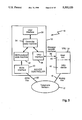
- FIG. 1 is a block diagram of a system for processing calls according to the invention.
- FIG. 2 is a block diagram of an alternative embodiment of a system for processing calls according to the invention.
- FIG. 3 is a block diagram of the software architecture for the FIG. 1 system.
- FIGS. 4-7 are diagrams illustrating steps in the processing of calls by the FIG. 1 system when employing shared call appearances.
- FIG. 8 is a diagram describing the protocol for the call processing illustrated in FIGS. 4-7.
- FIGS. 9-13 are diagrams illustrating steps in the processing of calls by the FIG. 1 system when employing call conferencing.
- FIG. 14 is a diagram describing the protocol for the call processing illustrated in FIGS. 9-13.
- FIG. 15 is a diagram of a system including two terminal devices connected to the same network connection.
- FIG. 16 is a diagram describing a protocol used to shift control of the network connection from one terminal device to the other in the FIG. 15 system.
- FIG. 17 is a diagram describing a protocol used to monitor the state of the network connection in the FIG. 15 system.
- System 10 for processing calls placed over telephone network 12.
- System 10 includes voice response unit 14 and device controller 16.
- Voice response unit 14 is connected to telephone network 12 via a plurality of analog lines 18. Voice response unit 14 receives incoming telephone calls over analog lines 18, plays voice messages and prompts, and receives touch tone responses from callers. Voice response unit 14 is, for example, an Infobot available from Syntellect, Inc., Phoenix, Ariz.
- Device controller 16 is a personal computer, e.g., model Premium II 486/33 available from AST Research, that has an ISDN interface card (e.g., PC53 available from DGM&S, Inc., Mt. Laurel, N.J.) and is connected to telephone network 12 via ISDN line 20.
- the software implementing the device controller may be executed either on the ISDN interface card or on the computer itself.
- Analog lines 18 provide a call connection interface that may not permit call transfer but does permit the voice response unit to engage and disengage a telephone call. The lines also permit a shared call appearance with ISDN line 20, or receipt of a conferenced call from ISDN line 20.
- Voice response unit 14 and device controller 16 communicate over direct message transfer link 22, voice response unit 14 sending informational messages to device controller 16, and device controller 16 sending control messages to voice response unit 14.
- Device controller 16 is connected to network 12 via an ISDN interface that does permit it to transfer telephone calls received over the network to another telephone, e.g., telephone 23.
- the ISDN interface serves as a call connection interface.
- device controller 24 and voice response unit 26 are part of the same physical equipment, for example, a personal computer with cards inserted for the device controller function and the ISDN interface function. In this case, communication between device controller 24 and voice response unit 26 is by internal message transfer interfaces 28 rather than by an external physical link.
- Device controller 16 includes the following functional modules: ISDN interface module 30, ISDN protocol state machine module 32, controller state machine module 34, voice response unit interface module 36 and user interface module 38. Events from ISDN line 20 and from voice response unit 14 are inputs to overall controller state machine 34. Configuration of device controller 16 is performed by user interface module 38. Management of voice response unit 10 by device controller 16 takes place over message transfer interfaces 39 linking the two control functions.
- host link software 40 enables voice response unit device 42 to communicate with and to take action based upon interaction with device controller 16.
- Host link software 40 configures voice response unit 14 to implement the control protocol used for communication with device controller 16.
- the transmission of informational messages and control messages between device controller 16 and voice response unit 14 can take place over different types of data interfaces, including those internal to a physical unit (as in FIG. 2) and those between physical units (as in FIG. 1).
- the informational and control messages can be transmitted using the X.25 service of the ISDN network itself; in this case, instead of one or more of the analog lines 18, there would be an ISDN line supporting multiple call appearances or call conferencing, and the logical connection labelled message transfer interfaces 39 would take place over the physical ISDN connection to the telephone network.
- Call appearances on an ISDN line are logical control channels for management of particular calls on that line.
- a call appearance can be "shared" between an analog line and an ISDN line, a feature known as shared call appearance (see discussion in AT&T 5 ESS Switch, ISDN Basic Rate Interface Specification, 5E6 Generic Program Document 235-900-321 or Bellcore ISDN Electronic Key Telephone Service Technical Reference TR-TSY-000205).
- shared call appearances are described as follows. If A and B share a call appearance, A can do anything to the call if B does not pick it up, and B will be able to watch all activity of A on the call appearance.
- a and B are connected to the call, they cannot hold, transfer or conference; moreover, drop/disconnect by A or B only disengages the dropper but does not drop the call, and neither A nor B can tell if the other is engaged or not.
- a particular limitation of a shared call appearance is that an ISDN line sharing a call appearance with an analog line cannot transfer a shared call which is active on that analog line.
- a second party can be added to a call.
- B can be added to participate in the call through the conferencing feature.
- A can then place itself on hold and permit B to be the sole party communicating with the outside call.
- A will not receive an indication if one of the two parties (e.g., the caller) disconnects the call.
- the Drop service which disconnects the last added leg, is used to provide this information. If the caller has hung up, the Drop service will disconnect the network connection; otherwise the Drop service merely removes the leg to B.
- the call conferencing and Drop service are, e.g., as described in AT&T 5ESS document referenced earlier.
- informational messages and control messages passed over message transfer link 22 allow device controller 16 and voice response unit 14 to coordinate their activities, and this coordination extends the capabilities of shared call appearances or call conferencing to provide complete control of voice response unit 14 and permit transfer of calls handled by it, even though calls cannot be transferred from an analog line 18.
- the message interface protocol described in FIG. 8 and illustrated in FIGS. 4-7 provides this call processing control using shared call appearances in spite of the limitations of analog lines and the shared call appearance function.
- the message interface protocol described in FIG. 14 and illustrated in FIGS. 9-13 provides this call processing control using call conferencing in spite of limitations of analog lines and the call conferencing function.
- FIGS. 4-8 the processing of a telephone call from caller 44 using the shared call appearance function is shown in four steps.
- ISDN call appearances 46, 48 are shown short horizontal lines extending from device controller 16, and physical analog lines 18 are shown as short horizontal lines extending from voice response unit 14.
- Call appearances 46 correspond one-to-one with analog lines 18 connected to voice response unit 10.
- Call appearances 48 are independent of voice response unit 14 and are used to manipulate calls on the ISDN line.
- Messages between voice response unit 14 and device controller 16 are shown as the arrows extending vertically between the two.
- the message interface protocol shows both the messages between VRU 14 and device controller 16 and the communications of VRU 14 and device controller 16 with the network over the call connection interfaces.
- FIG. 4 shows caller 44 interacting with voice response unit 14, the first step.
- Caller 44 is shown associated with both a line 18 to voice response unit 14 and the corresponding shared call appearance 46 of the ISDN line connected to device controller 16.
- Voice response unit 14 is actively connected to the call, as is indicated by the heavy line from caller 44 to it on FIG. 4.
- the ISDN line is not connected to caller 44, so device controller 16 can monitor the state of the analog line and be directly informed if caller 44 hangs up.
- the diagram shows information messages between device controller 16 and voice response unit 14 relating to the digit collection function of voice response unit 14.
- Voice response unit 14 plays the message and receives touch-tone digits from caller 44 in response to the message.
- Voice response unit 14 then communicates the digits to device controller 16 and indicates when the announcement or other interaction with caller 44 has been completed.
- device controller 16 is shown preparing to transfer the call away from voice response unit 14, something that unit 14 is incapable of doing efficiently or at all on its own, owing to the limited functionality of analog lines 18.
- Device controller 16 initiates an outgoing call to the eventual destination of the call from caller 44. This is shown by outgoing arrow 50 from an unshared call appearance 48 at device controller 16. This speeds up the process of transfer because the outgoing leg will be ready as soon as the call is in a state in which it can be transferred.
- Device controller 16 then connects to the call from caller 44 via the shared call appearance, permitting it to eventually exercise control over the call from caller 44. (This is shown by the heavy line to controller 16 on FIG. 5.)
- Next device controller 16 sends a control message, via the message transfer interface, to voice response unit 14 telling the latter to hang up on the call.
- voice response unit 14 is shown after having hung up so that the call appearance at device controller 16 is the only connection to caller 44. After voice response unit 14 has disconnected, it informs device controller 16 that is has done so via an acknowledgment message passed over the message transfer interface. Once device controller 16 receives this message, it knows that it has sole control of the call from caller 44 and hence has the power to transfer the call. Device controller 16 then issues a call transfer message to network 12 directing that the (incoming) call from caller 44 on the shared call appearance 46 be transferred to (outgoing) call 50 on the unshared call appearance 48.
- FIG. 7 shows the result. Caller 44 is now connected to the destination of the outgoing call, and neither device controller 16 nor voice response unit 14 has anything to do with the call.
- ISDN call transfer has been performed following receipt of information from a caller by a voice response unit connected to an analog line.
- FIG. 9 shows the initial step. An incoming call is made from caller 44 to device controller 16.
- device controller 16 sends a message to the network to establish a call leg to the voice response unit.
- Device controller 16 requests the network to place the voice response unit leg on hold.
- the network sends a message to device controller 16 indicating that the call has arrived.
- Device controller 16 requests the network to conference the leg to voice response unit 14 and the call from caller 44 and to place itself on hold, as indicated on FIG. 14.
- device controller 16 sends, via the message transfer interfaces, a control message to voice response unit 14 instructing it to play an announcement.
- Voice response unit 14 plays the announcement to caller 44 and receives touch-tone digits from caller 44 in response to the message. The digits are then communicated to device controller 16 along with an announcement done message.
- device controller 16 then places a call to the eventual destination of the call from caller 44, as indicated by arrow 50 on FIG. 11.
- the eventual destination could be an agent.
- device controller 16 must check that caller 44 did not hang up while connected to voice response unit 14. It does this by issuing a Drop message to the network. This disconnects the last leg added to the call. Normally, this will disconnect voice response unit 14, so that the connection from caller 44 to device controller 16 remains. If caller 44 has hung up, the Drop message will cause the network to release the network connection, so no transfer need take place.
- voice response unit 14 will have been disconnected by the Drop message but may not necessarily know that it has been disconnected and is free to take another call. Accordingly, device controller 16 sends a "disconnected" message, via the message transfer interface, to voice response unit 14, instructing the latter that it has been disconnected. Voice response unit 14 then sends a "disconnect acknowledge" message to device controller 16.
- the leg to device controller 16 is the only connection to caller 44.
- Device controller 16 issues a call transfer message to network 12 requesting that the incoming call from caller 44 be transferred to the outgoing leg 50.
- FIG. 13 shows the result. Caller 44 is now connected to the destination of the outgoing call, and neither device controller 16 nor voice response unit 14 has anything to do with the call.
- call handling devices can be used in the practice of the invention.
- the device controller could initiate a transfer (e.g., as soon as an agent becomes available).
- private networks can be used.
- ISDN and analog shared call appearances there can be ISDN and ISDN shared call appearances and ISDN and T-1 shared call appearances where available.
- the shared call appearances can be between proprietary PBX sets and between those sets and other types of lines (analog, ISDN, and T-1), where supported.
- voice and data call connection interfaces can be used in place of analog lines 18 and ISDN line 20 for connecting the call handling device and the device controller to the network so long as certain requirements are met for the call connection interfaces.
- Each of the interfaces must permit establishing and releasing a network connection and participation with another call connection interface in the same network connection.
- the interface for the device controller must additionally permit either control over a network connection when the interface is the sole interface participating in that connection or control over the network connection to drop the last leg added to a connection.
- connection to network 60 is shown connected via network interface 62 to terminal 64 and via network interface 66 to terminal 68.
- FIG. 16 shows the steps in the protocol providing shift of connection control for connection 60.
- network connection 60 is present only at network interface 62, and network interface 62 has control of connection 60.
- terminal 64 sends a "shift control" message to terminal 68, identifying connection 60 as the connection to be moved.
- Terminal 68 then commands network interface 66 to participate in the specified connection.
- terminal 68 When a network action has been successfully performed, terminal 68 sends a "release network” message to terminal 64 identifying connection 60 to be released. Terminal 64 then commands network interface 62 to withdraw from connection 60. When this network action has been successfully performed, terminal 64 returns a "network released” message to terminal 68 informing terminal 68 that network interface 66 now has control of connection 60. Now terminal 68 can perform any network control action supported by its feature set. A "request control" message could proceed the entire message exchange if terminal 68 were to initiate the shift of control.
- the invention also provides a means to monitor and control the state of a network connection from a network interface that is not participating in the connection.
- FIG. 17 describes a protocol for this to take place. It is similar to the FIG. 14 protocol, except that the specific messages have been replaced with "info messages" on FIG. 17, and the "transfer” command has been replaced with "invoke network control action".
- the Drop command is used to monitor the state of the network connection. After the leg to terminal 68 has been disconnected, terminal 64 is the sole terminal at the connection.
Abstract
Description
Claims (98)
Priority Applications (6)
| Application Number | Priority Date | Filing Date | Title |
|---|---|---|---|
| US07/875,069 US5333133A (en) | 1992-04-28 | 1992-04-28 | Call processing control system |
| JP5519268A JPH07509816A (en) | 1992-04-28 | 1993-04-06 | call processing control system |
| PCT/US1993/003226 WO1993022863A1 (en) | 1992-04-28 | 1993-04-06 | Call processing control system |
| AU39747/93A AU3974793A (en) | 1992-04-28 | 1993-04-06 | Call processing control system |
| CA002131622A CA2131622C (en) | 1992-04-28 | 1993-04-06 | Call processing control system |
| EP93909268A EP0642722A4 (en) | 1992-04-28 | 1993-04-06 | Call processing control system. |
Applications Claiming Priority (1)
| Application Number | Priority Date | Filing Date | Title |
|---|---|---|---|
| US07/875,069 US5333133A (en) | 1992-04-28 | 1992-04-28 | Call processing control system |
Publications (1)
| Publication Number | Publication Date |
|---|---|
| US5333133A true US5333133A (en) | 1994-07-26 |
Family
ID=25365154
Family Applications (1)
| Application Number | Title | Priority Date | Filing Date |
|---|---|---|---|
| US07/875,069 Expired - Lifetime US5333133A (en) | 1992-04-28 | 1992-04-28 | Call processing control system |
Country Status (6)
| Country | Link |
|---|---|
| US (1) | US5333133A (en) |
| EP (1) | EP0642722A4 (en) |
| JP (1) | JPH07509816A (en) |
| AU (1) | AU3974793A (en) |
| CA (1) | CA2131622C (en) |
| WO (1) | WO1993022863A1 (en) |
Cited By (44)
| Publication number | Priority date | Publication date | Assignee | Title |
|---|---|---|---|---|
| US5490247A (en) * | 1993-11-24 | 1996-02-06 | Intel Corporation | Video subsystem for computer-based conferencing system |
| US5493568A (en) * | 1993-11-24 | 1996-02-20 | Intel Corporation | Media dependent module interface for computer-based conferencing system |
| US5506954A (en) * | 1993-11-24 | 1996-04-09 | Intel Corporation | PC-based conferencing system |
| US5526416A (en) * | 1992-11-16 | 1996-06-11 | Dezonno; Anthony J. | Automatic call distribution system with an ISDN compatible call connection system and method |
| US5566238A (en) * | 1993-11-24 | 1996-10-15 | Intel Corporation | Distributed processing of audio signals |
| US5574934A (en) * | 1993-11-24 | 1996-11-12 | Intel Corporation | Preemptive priority-based transmission of signals using virtual channels |
| US5579389A (en) * | 1993-11-24 | 1996-11-26 | Intel Corporation | Histogram-based processing of audio signals |
| US5592547A (en) * | 1993-11-24 | 1997-01-07 | Intel Corporation | Processing audio signals using a discrete state machine |
| US5600797A (en) * | 1993-11-24 | 1997-02-04 | Intel Corporation | System for identifying new client and allocating bandwidth thereto by monitoring transmission of message received periodically from client computers informing of their current status |
| US5631967A (en) * | 1993-11-24 | 1997-05-20 | Intel Corporation | Processing audio signals using a state variable |
| US5640449A (en) * | 1992-08-14 | 1997-06-17 | International Business Machines Corporation | Communications device to establish call in ISDN system |
| US5673393A (en) * | 1993-11-24 | 1997-09-30 | Intel Corporation | Managing bandwidth over a computer network having a management computer that allocates bandwidth to client computers upon request |
| US5754765A (en) * | 1993-11-24 | 1998-05-19 | Intel Corporation | Automatic transport detection by attempting to establish communication session using list of possible transports and corresponding media dependent modules |
| US5809237A (en) * | 1993-11-24 | 1998-09-15 | Intel Corporation | Registration of computer-based conferencing system |
| US5848143A (en) | 1995-03-02 | 1998-12-08 | Geotel Communications Corp. | Communications system using a central controller to control at least one network and agent system |
| US5862388A (en) * | 1993-11-24 | 1999-01-19 | Intel Corporation | Interrupt-time processing of received signals |
| US5896500A (en) * | 1993-10-01 | 1999-04-20 | Collaboration Properties, Inc. | System for call request which results in first and second call handle defining call state consisting of active or hold for its respective AV device |
| US5903734A (en) * | 1993-06-22 | 1999-05-11 | Canon Kabushiki Kaisha | Multimedia information communication apparatus which stores received information in an encoded state |
| US5949891A (en) * | 1993-11-24 | 1999-09-07 | Intel Corporation | Filtering audio signals from a combined microphone/speaker earpiece |
| US6125398A (en) * | 1993-11-24 | 2000-09-26 | Intel Corporation | Communications subsystem for computer-based conferencing system using both ISDN B channels for transmission |
| WO2002021815A2 (en) * | 2000-09-04 | 2002-03-14 | Telefonaktiebolaget Lm Ericsson (Publ) | Line control apparatus, control method therefor, and telephone communication system |
| US6366575B1 (en) | 1996-11-01 | 2002-04-02 | Teloquent Communications Corporation | Extended access for automatic call distributing system |
| US20020124051A1 (en) * | 1993-10-01 | 2002-09-05 | Ludwig Lester F. | Marking and searching capabilities in multimedia documents within multimedia collaboration networks |
| US20020164010A1 (en) * | 2001-05-04 | 2002-11-07 | Siemens Information And Communication Networks, Inc. | Methods and apparatus for controlling call handling in a communications network |
| US20020164011A1 (en) * | 2001-05-04 | 2002-11-07 | Siemens Information & Communication Networks, Inc. | Methods and apparatus for controlling call pullback by an automatic call distribution (ACD) system from an interactive voice response (IVR) system and for allowing an ACD caller to complete a critical transaction while connected to the IVR |
| US20020168062A1 (en) * | 2001-05-04 | 2002-11-14 | Siemens Information And Communication Networks, Inc. | Methods and apparatus for automatically determining a call service request |
| US6560329B1 (en) | 1999-04-29 | 2003-05-06 | Teloquent Communications Corporation | Automated call routing system |
| US6633539B1 (en) | 1998-08-28 | 2003-10-14 | Cisco Technology, Inc. | Device, method and article of manufacture for call setup pacing in connection-oriented networks |
| US6665393B1 (en) | 2000-06-16 | 2003-12-16 | Cisco Technology, Inc. | Call routing control using call routing scripts |
| US6704412B1 (en) | 1998-09-24 | 2004-03-09 | Bechtel Bwxt Idaho, Llc | Systems configured to distribute a telephone call, communication systems, communication methods and methods of routing a telephone call to a service representative |
| US20040085914A1 (en) * | 1999-10-25 | 2004-05-06 | Baxley Warren E. | Large-scale, fault-tolerant audio conferencing in a purely packet-switched network |
| US6807269B1 (en) | 2000-07-20 | 2004-10-19 | Cisco Technology, Inc. | Call management implemented using call routing engine |
| US6819754B1 (en) | 2000-08-29 | 2004-11-16 | Cisco Technology, Inc. | Generation of communication system control scripts |
| US6898620B1 (en) | 1996-06-07 | 2005-05-24 | Collaboration Properties, Inc. | Multiplexing video and control signals onto UTP |
| US20050237379A1 (en) * | 2004-04-23 | 2005-10-27 | Brooksby Scot L | System and method for collection and redistribution of video conferences |
| US20050238143A1 (en) * | 2004-04-23 | 2005-10-27 | Clapp Glenn D | Method and system for electronic communication with the hearing impaired |
| US20050238144A1 (en) * | 2004-04-23 | 2005-10-27 | Flathers Michael D | Method and system for call restoration in a video relay service |
| US7185054B1 (en) | 1993-10-01 | 2007-02-27 | Collaboration Properties, Inc. | Participant display and selection in video conference calls |
| US20070093672A1 (en) * | 2005-10-21 | 2007-04-26 | Catalytic Distillation Technologies | Process for producing organic carbonates |
| US20070091915A1 (en) * | 2000-04-19 | 2007-04-26 | Serconet Ltd. | Network combining wired and non wired segments |
| US20090009610A1 (en) * | 2000-07-26 | 2009-01-08 | Anderson Eric C | Automatically Configuring A Web-Enabled Digital Camera To Access The Internet |
| US8224776B1 (en) | 2000-07-26 | 2012-07-17 | Kdl Scan Designs Llc | Method and system for hosting entity-specific photo-sharing websites for entity-specific digital cameras |
| US8868778B2 (en) | 2000-10-06 | 2014-10-21 | Kdl Scan Designs Llc | Transmission bandwidth and memory requirements reduction in a portable image capture device |
| US20230005482A1 (en) * | 2019-05-06 | 2023-01-05 | Google Llc | Automated calling system |
Citations (13)
| Publication number | Priority date | Publication date | Assignee | Title |
|---|---|---|---|---|
| US4573140A (en) * | 1983-03-30 | 1986-02-25 | Voicetek Corporation | Method of and apparatus for voice communication storage and forwarding with simultaneous access to multiple users |
| US4663777A (en) * | 1984-12-17 | 1987-05-05 | Charles Szeto | Apparatus for controlling digital voice recording and playback over telephone lines and adapted for use with standard host computers |
| US4763353A (en) * | 1986-02-14 | 1988-08-09 | American Telephone And Telegraph Company | Terminal based adjunct call manager for a communication system |
| US4893328A (en) * | 1987-07-31 | 1990-01-09 | Microvoice Systems Corporation | Automated telephone operator overflow device |
| US4979206A (en) * | 1987-07-10 | 1990-12-18 | At&T Bell Laboratories | Directory assistance systems |
| US4980908A (en) * | 1989-05-30 | 1990-12-25 | Voicetek Corporation | Voice-switched gain control for voice communication equipment connected to telephone lines |
| US5003575A (en) * | 1987-12-24 | 1991-03-26 | Chamberlin David B | Method and apparatus for storing and forwarding voice signals with controlled access |
| US5020095A (en) * | 1988-11-16 | 1991-05-28 | Dytel Corporation | Interactive call distribution processor |
| US5023868A (en) * | 1988-12-29 | 1991-06-11 | At&T Bell Laboratories | Automated call handling apparatus |
| US5036535A (en) * | 1989-11-27 | 1991-07-30 | Unifi Communications Corporation | Switchless automatic call distribution system |
| US5062103A (en) * | 1988-12-29 | 1991-10-29 | At&T Bell Laboratories | Telephone agent call management system |
| US5134647A (en) * | 1990-03-19 | 1992-07-28 | Messager Partners | Automatic voice/data messaging enhancements |
| US5168515A (en) * | 1989-11-27 | 1992-12-01 | Unifi Communications Corporation | Switchless automatic call distribution system |
-
1992
- 1992-04-28 US US07/875,069 patent/US5333133A/en not_active Expired - Lifetime
-
1993
- 1993-04-06 CA CA002131622A patent/CA2131622C/en not_active Expired - Fee Related
- 1993-04-06 WO PCT/US1993/003226 patent/WO1993022863A1/en not_active Application Discontinuation
- 1993-04-06 JP JP5519268A patent/JPH07509816A/en not_active Ceased
- 1993-04-06 AU AU39747/93A patent/AU3974793A/en not_active Abandoned
- 1993-04-06 EP EP93909268A patent/EP0642722A4/en not_active Withdrawn
Patent Citations (13)
| Publication number | Priority date | Publication date | Assignee | Title |
|---|---|---|---|---|
| US4573140A (en) * | 1983-03-30 | 1986-02-25 | Voicetek Corporation | Method of and apparatus for voice communication storage and forwarding with simultaneous access to multiple users |
| US4663777A (en) * | 1984-12-17 | 1987-05-05 | Charles Szeto | Apparatus for controlling digital voice recording and playback over telephone lines and adapted for use with standard host computers |
| US4763353A (en) * | 1986-02-14 | 1988-08-09 | American Telephone And Telegraph Company | Terminal based adjunct call manager for a communication system |
| US4979206A (en) * | 1987-07-10 | 1990-12-18 | At&T Bell Laboratories | Directory assistance systems |
| US4893328A (en) * | 1987-07-31 | 1990-01-09 | Microvoice Systems Corporation | Automated telephone operator overflow device |
| US5003575A (en) * | 1987-12-24 | 1991-03-26 | Chamberlin David B | Method and apparatus for storing and forwarding voice signals with controlled access |
| US5020095A (en) * | 1988-11-16 | 1991-05-28 | Dytel Corporation | Interactive call distribution processor |
| US5023868A (en) * | 1988-12-29 | 1991-06-11 | At&T Bell Laboratories | Automated call handling apparatus |
| US5062103A (en) * | 1988-12-29 | 1991-10-29 | At&T Bell Laboratories | Telephone agent call management system |
| US4980908A (en) * | 1989-05-30 | 1990-12-25 | Voicetek Corporation | Voice-switched gain control for voice communication equipment connected to telephone lines |
| US5036535A (en) * | 1989-11-27 | 1991-07-30 | Unifi Communications Corporation | Switchless automatic call distribution system |
| US5168515A (en) * | 1989-11-27 | 1992-12-01 | Unifi Communications Corporation | Switchless automatic call distribution system |
| US5134647A (en) * | 1990-03-19 | 1992-07-28 | Messager Partners | Automatic voice/data messaging enhancements |
Non-Patent Citations (3)
| Title |
|---|
| Luhmann, Rick, "IVR Trends", Interactive Voice Response, Teleconnect, Sep. 1991, pp. 106, 108-112. |
| Luhmann, Rick, IVR Trends , Interactive Voice Response, Teleconnect, Sep. 1991, pp. 106, 108 112. * |
| Voicetek Corporation, "VoiceTek Corporation: Product Overview". * |
Cited By (102)
| Publication number | Priority date | Publication date | Assignee | Title |
|---|---|---|---|---|
| US5640449A (en) * | 1992-08-14 | 1997-06-17 | International Business Machines Corporation | Communications device to establish call in ISDN system |
| US5526416A (en) * | 1992-11-16 | 1996-06-11 | Dezonno; Anthony J. | Automatic call distribution system with an ISDN compatible call connection system and method |
| US5903734A (en) * | 1993-06-22 | 1999-05-11 | Canon Kabushiki Kaisha | Multimedia information communication apparatus which stores received information in an encoded state |
| US6959322B2 (en) | 1993-10-01 | 2005-10-25 | Collaboration Properties, Inc. | UTP based video conferencing |
| US7730132B2 (en) | 1993-10-01 | 2010-06-01 | Ludwig Lester F | Storing and accessing media files |
| US7152093B2 (en) | 1993-10-01 | 2006-12-19 | Collaboration Properties, Inc. | System for real-time communication between plural users |
| US20070078931A1 (en) * | 1993-10-01 | 2007-04-05 | Collaboration Properties, Inc. | System for Managing Real-Time Communications |
| US6789105B2 (en) | 1993-10-01 | 2004-09-07 | Collaboration Properties, Inc. | Multiple-editor authoring of multimedia documents including real-time video and time-insensitive media |
| US20070078932A1 (en) * | 1993-10-01 | 2007-04-05 | Collaboration Properties, Inc. | Audio Communication with Login Location Addressing |
| US20070083596A1 (en) * | 1993-10-01 | 2007-04-12 | Collaboration Properties, Inc. | Storing and Accessing Media Files |
| US20030187940A1 (en) * | 1993-10-01 | 2003-10-02 | Collaboration Properties, Inc. | Teleconferencing employing multiplexing of video and data conferencing signals |
| US20030158901A1 (en) * | 1993-10-01 | 2003-08-21 | Collaboration Properties, Inc. | UTP based video conferencing |
| US6594688B2 (en) | 1993-10-01 | 2003-07-15 | Collaboration Properties, Inc. | Dedicated echo canceler for a workstation |
| US7054904B2 (en) | 1993-10-01 | 2006-05-30 | Collaboration Properties, Inc. | Marking and searching capabilities in multimedia documents within multimedia collaboration networks |
| US6212547B1 (en) | 1993-10-01 | 2001-04-03 | Collaboration Properties, Inc. | UTP based video and data conferencing |
| US7206809B2 (en) | 1993-10-01 | 2007-04-17 | Collaboration Properties, Inc. | Method for real-time communication between plural users |
| US7185054B1 (en) | 1993-10-01 | 2007-02-27 | Collaboration Properties, Inc. | Participant display and selection in video conference calls |
| US7822813B2 (en) | 1993-10-01 | 2010-10-26 | Ludwig Lester F | Storing and accessing media files |
| US7831663B2 (en) | 1993-10-01 | 2010-11-09 | Pragmatus Av Llc | Storage and playback of media files |
| US20020124051A1 (en) * | 1993-10-01 | 2002-09-05 | Ludwig Lester F. | Marking and searching capabilities in multimedia documents within multimedia collaboration networks |
| US6437818B1 (en) | 1993-10-01 | 2002-08-20 | Collaboration Properties, Inc. | Video conferencing on existing UTP infrastructure |
| US6426769B1 (en) | 1993-10-01 | 2002-07-30 | Collaboration Properties, Inc. | High-quality switched analog video communications over unshielded twisted pair |
| US7908320B2 (en) | 1993-10-01 | 2011-03-15 | Pragmatus Av Llc | Tracking user locations over multiple networks to enable real time communications |
| US6351762B1 (en) | 1993-10-01 | 2002-02-26 | Collaboration Properties, Inc. | Method and system for log-in-based video and multimedia calls |
| US5896500A (en) * | 1993-10-01 | 1999-04-20 | Collaboration Properties, Inc. | System for call request which results in first and second call handle defining call state consisting of active or hold for its respective AV device |
| US20060059266A1 (en) * | 1993-10-01 | 2006-03-16 | Collaboration Properties, Inc. | Registration based addressing over multiple networks with digital audio communication |
| US6343314B1 (en) | 1993-10-01 | 2002-01-29 | Collaboration Properties, Inc. | Remote participant hold and disconnect during videoconferencing |
| US6237025B1 (en) | 1993-10-01 | 2001-05-22 | Collaboration Properties, Inc. | Multimedia collaboration system |
| US5663951A (en) * | 1993-11-24 | 1997-09-02 | Intel Corporation | Delayed transmission of data packets over networks |
| US5673393A (en) * | 1993-11-24 | 1997-09-30 | Intel Corporation | Managing bandwidth over a computer network having a management computer that allocates bandwidth to client computers upon request |
| US5949891A (en) * | 1993-11-24 | 1999-09-07 | Intel Corporation | Filtering audio signals from a combined microphone/speaker earpiece |
| US5913062A (en) * | 1993-11-24 | 1999-06-15 | Intel Corporation | Conference system having an audio manager using local and remote audio stream state machines for providing audio control functions during a conference session |
| US5493568A (en) * | 1993-11-24 | 1996-02-20 | Intel Corporation | Media dependent module interface for computer-based conferencing system |
| US6354748B1 (en) | 1993-11-24 | 2002-03-12 | Intel Corporation | Playing audio files at high priority |
| US5862388A (en) * | 1993-11-24 | 1999-01-19 | Intel Corporation | Interrupt-time processing of received signals |
| US5506832A (en) * | 1993-11-24 | 1996-04-09 | Intel Corporation | Remote confidence testing for computer-based conferencing system |
| US5859979A (en) * | 1993-11-24 | 1999-01-12 | Intel Corporation | System for negotiating conferencing capabilities by selecting a subset of a non-unique set of conferencing capabilities to specify a unique set of conferencing capabilities |
| US5506954A (en) * | 1993-11-24 | 1996-04-09 | Intel Corporation | PC-based conferencing system |
| US5809237A (en) * | 1993-11-24 | 1998-09-15 | Intel Corporation | Registration of computer-based conferencing system |
| US5794018A (en) * | 1993-11-24 | 1998-08-11 | Intel Corporation | System and method for synchronizing data streams |
| US5774674A (en) * | 1993-11-24 | 1998-06-30 | Intel Corporation | System for negotiating at least two sets of video capabilities between two nodes to perform video conferencing between the nodes according to the selected set |
| US5524110A (en) * | 1993-11-24 | 1996-06-04 | Intel Corporation | Conferencing over multiple transports |
| US5754765A (en) * | 1993-11-24 | 1998-05-19 | Intel Corporation | Automatic transport detection by attempting to establish communication session using list of possible transports and corresponding media dependent modules |
| US6125398A (en) * | 1993-11-24 | 2000-09-26 | Intel Corporation | Communications subsystem for computer-based conferencing system using both ISDN B channels for transmission |
| US5631967A (en) * | 1993-11-24 | 1997-05-20 | Intel Corporation | Processing audio signals using a state variable |
| US5600797A (en) * | 1993-11-24 | 1997-02-04 | Intel Corporation | System for identifying new client and allocating bandwidth thereto by monitoring transmission of message received periodically from client computers informing of their current status |
| US5592547A (en) * | 1993-11-24 | 1997-01-07 | Intel Corporation | Processing audio signals using a discrete state machine |
| US5566238A (en) * | 1993-11-24 | 1996-10-15 | Intel Corporation | Distributed processing of audio signals |
| US5590128A (en) * | 1993-11-24 | 1996-12-31 | Intel Corporation | Dial lists for computer-based conferencing systems |
| US5490247A (en) * | 1993-11-24 | 1996-02-06 | Intel Corporation | Video subsystem for computer-based conferencing system |
| US5574934A (en) * | 1993-11-24 | 1996-11-12 | Intel Corporation | Preemptive priority-based transmission of signals using virtual channels |
| US5579389A (en) * | 1993-11-24 | 1996-11-26 | Intel Corporation | Histogram-based processing of audio signals |
| US5848143A (en) | 1995-03-02 | 1998-12-08 | Geotel Communications Corp. | Communications system using a central controller to control at least one network and agent system |
| US5878130A (en) | 1995-03-02 | 1999-03-02 | Geotel Communications Corp | Communications system and method for operating same |
| US6898620B1 (en) | 1996-06-07 | 2005-05-24 | Collaboration Properties, Inc. | Multiplexing video and control signals onto UTP |
| US6366575B1 (en) | 1996-11-01 | 2002-04-02 | Teloquent Communications Corporation | Extended access for automatic call distributing system |
| US20040047288A1 (en) * | 1998-08-28 | 2004-03-11 | Claude Basso | Call setup pacing in computer networks |
| US6633539B1 (en) | 1998-08-28 | 2003-10-14 | Cisco Technology, Inc. | Device, method and article of manufacture for call setup pacing in connection-oriented networks |
| US7751435B2 (en) | 1998-08-28 | 2010-07-06 | Cisco Technology, Inc. | Call setup pacing in computer networks |
| US6704412B1 (en) | 1998-09-24 | 2004-03-09 | Bechtel Bwxt Idaho, Llc | Systems configured to distribute a telephone call, communication systems, communication methods and methods of routing a telephone call to a service representative |
| US6560329B1 (en) | 1999-04-29 | 2003-05-06 | Teloquent Communications Corporation | Automated call routing system |
| US20040085914A1 (en) * | 1999-10-25 | 2004-05-06 | Baxley Warren E. | Large-scale, fault-tolerant audio conferencing in a purely packet-switched network |
| US8848725B2 (en) | 2000-04-19 | 2014-09-30 | Conversant Intellectual Property Management Incorporated | Network combining wired and non-wired segments |
| US8867506B2 (en) | 2000-04-19 | 2014-10-21 | Conversant Intellectual Property Management Incorporated | Network combining wired and non-wired segments |
| US7636373B2 (en) | 2000-04-19 | 2009-12-22 | Mosaid Technologies Incorporated | Network combining wired and non-wired segments |
| US8873575B2 (en) | 2000-04-19 | 2014-10-28 | Conversant Intellectual Property Management Incorporated | Network combining wired and non-wired segments |
| US20070091915A1 (en) * | 2000-04-19 | 2007-04-26 | Serconet Ltd. | Network combining wired and non wired segments |
| US8873586B2 (en) | 2000-04-19 | 2014-10-28 | Conversant Intellectual Property Management Incorporated | Network combining wired and non-wired segments |
| US8982904B2 (en) | 2000-04-19 | 2015-03-17 | Conversant Intellectual Property Management Inc. | Network combining wired and non-wired segments |
| US8982903B2 (en) | 2000-04-19 | 2015-03-17 | Conversant Intellectual Property Management Inc. | Network combining wired and non-wired segments |
| US6665393B1 (en) | 2000-06-16 | 2003-12-16 | Cisco Technology, Inc. | Call routing control using call routing scripts |
| US7162021B1 (en) | 2000-06-16 | 2007-01-09 | Cisco Technology, Inc. | Call routing control using call routing scripts |
| US7088812B1 (en) | 2000-07-20 | 2006-08-08 | Cisco Technology, Inc. | Call management implemented using call routing engine |
| US6807269B1 (en) | 2000-07-20 | 2004-10-19 | Cisco Technology, Inc. | Call management implemented using call routing engine |
| US9906703B2 (en) | 2000-07-26 | 2018-02-27 | Chemtron Research Llc | Method and system for hosting entity-specific photo-sharing websites for entity-specific digital cameras |
| US9118740B2 (en) | 2000-07-26 | 2015-08-25 | Kdl Scan Designs Llc | Method and system for hosting entity-specific photo-sharing websites for entity-specific digital cameras |
| US20090009610A1 (en) * | 2000-07-26 | 2009-01-08 | Anderson Eric C | Automatically Configuring A Web-Enabled Digital Camera To Access The Internet |
| US9276968B2 (en) | 2000-07-26 | 2016-03-01 | Chemtron Research Llc | Automatically configuring a web-enabled portable device to access the internet |
| US9736196B2 (en) | 2000-07-26 | 2017-08-15 | Chemtron Research Llc | Automatically configuring a web-enabled portable device to access the internet |
| US8009194B2 (en) * | 2000-07-26 | 2011-08-30 | Fotomedia Technologies, Llc | Automatically configuring a web-enabled digital camera to access the internet |
| US10462349B2 (en) | 2000-07-26 | 2019-10-29 | Chemtron Research Llc | Method and system for hosting entity-specific photo-sharing web sites for entity-specific digital cameras |
| US8645325B2 (en) | 2000-07-26 | 2014-02-04 | Kdl Scan Designs Llc | Method and system for hosting entity-specific photo-sharing websites for entity-specific digital cameras |
| US8572663B2 (en) | 2000-07-26 | 2013-10-29 | Kdl Scan Designs Llc | Automatically configuring a web-enabled portable device to access the internet |
| US8224776B1 (en) | 2000-07-26 | 2012-07-17 | Kdl Scan Designs Llc | Method and system for hosting entity-specific photo-sharing websites for entity-specific digital cameras |
| US6819754B1 (en) | 2000-08-29 | 2004-11-16 | Cisco Technology, Inc. | Generation of communication system control scripts |
| WO2002021815A3 (en) * | 2000-09-04 | 2002-12-27 | Ericsson Telefon Ab L M | Line control apparatus, control method therefor, and telephone communication system |
| WO2002021815A2 (en) * | 2000-09-04 | 2002-03-14 | Telefonaktiebolaget Lm Ericsson (Publ) | Line control apparatus, control method therefor, and telephone communication system |
| US8868778B2 (en) | 2000-10-06 | 2014-10-21 | Kdl Scan Designs Llc | Transmission bandwidth and memory requirements reduction in a portable image capture device |
| US6940963B2 (en) * | 2001-05-04 | 2005-09-06 | Siemens Information And Communication Networks, Inc. | Methods and apparatus for automatically determining a call service request |
| US20020164010A1 (en) * | 2001-05-04 | 2002-11-07 | Siemens Information And Communication Networks, Inc. | Methods and apparatus for controlling call handling in a communications network |
| US20020164011A1 (en) * | 2001-05-04 | 2002-11-07 | Siemens Information & Communication Networks, Inc. | Methods and apparatus for controlling call pullback by an automatic call distribution (ACD) system from an interactive voice response (IVR) system and for allowing an ACD caller to complete a critical transaction while connected to the IVR |
| US20020168062A1 (en) * | 2001-05-04 | 2002-11-14 | Siemens Information And Communication Networks, Inc. | Methods and apparatus for automatically determining a call service request |
| US6819755B2 (en) * | 2001-05-04 | 2004-11-16 | Siemens Information And Communication Networks, Inc. | Methods and apparatus for controlling call handling in a communications network |
| US6819756B2 (en) * | 2001-05-04 | 2004-11-16 | Siemens Information And Communication Networks, Inc. | Methods and apparatus for controlling call pullback by an automatic call distribution (acd) system from an interactive voice response (ivr) system and for allowing an acd caller to complete a critical transaction while connected to the ivr |
| US7206386B2 (en) | 2004-04-23 | 2007-04-17 | Sorenson Communications, Inc. | Method and system for electronic communication with the hearing impaired |
| US7583286B2 (en) | 2004-04-23 | 2009-09-01 | Sorenson Media, Inc. | System and method for collection and redistribution of video conferences |
| US7016479B2 (en) | 2004-04-23 | 2006-03-21 | Sorenson Communications, Inc. | Method and system for call restoration in a video relay service |
| US20050237379A1 (en) * | 2004-04-23 | 2005-10-27 | Brooksby Scot L | System and method for collection and redistribution of video conferences |
| US20050238144A1 (en) * | 2004-04-23 | 2005-10-27 | Flathers Michael D | Method and system for call restoration in a video relay service |
| US20050238143A1 (en) * | 2004-04-23 | 2005-10-27 | Clapp Glenn D | Method and system for electronic communication with the hearing impaired |
| US20070093672A1 (en) * | 2005-10-21 | 2007-04-26 | Catalytic Distillation Technologies | Process for producing organic carbonates |
| US20230005482A1 (en) * | 2019-05-06 | 2023-01-05 | Google Llc | Automated calling system |
Also Published As
| Publication number | Publication date |
|---|---|
| EP0642722A1 (en) | 1995-03-15 |
| WO1993022863A1 (en) | 1993-11-11 |
| CA2131622C (en) | 1999-01-12 |
| CA2131622A1 (en) | 1993-11-11 |
| EP0642722A4 (en) | 1998-09-02 |
| AU3974793A (en) | 1993-11-29 |
| JPH07509816A (en) | 1995-10-26 |
Similar Documents
| Publication | Publication Date | Title |
|---|---|---|
| US5333133A (en) | Call processing control system | |
| US4691347A (en) | Method and apparatus for controlling a conference | |
| JP4087941B2 (en) | Integrated computer and telephone system | |
| US5291492A (en) | Externally controlled call processing system | |
| US4540850A (en) | Method and apparatus for controlling a conference | |
| US4653045A (en) | Interactive facility control arrangement | |
| US5373549A (en) | Multi-level conference management and notification | |
| US5475747A (en) | Telephone terminal controlled conference inspection | |
| US5758285A (en) | Increasing the capacity of a personal communication service system by multiple connections to individual telephone links | |
| JP2608795B2 (en) | Telephone exchange connection control method | |
| JPH0758996B2 (en) | Line configuration method | |
| JP2786458B2 (en) | ISDN telephone terminal | |
| JPS61216559A (en) | No-reply call recording system | |
| JP3008720B2 (en) | ISDN signal switching equipment | |
| JPH0343821B2 (en) | ||
| JPH0774832A (en) | Private branch exchange system | |
| JPH0442861B2 (en) | ||
| JPH0366869B2 (en) | ||
| JPH04129365A (en) | Acd silent monitor control system | |
| JPS62245755A (en) | Communication system in exchange system | |
| JPS61253968A (en) | Switching control method for combined private branch exchange | |
| JPH03127529A (en) | User-user information transfer confirming service system | |
| JPS6291041A (en) | Communication terminal control equipment | |
| JPH01168150A (en) | Call transfer system | |
| JPH03291040A (en) | Call request control system |
Legal Events
| Date | Code | Title | Description |
|---|---|---|---|
| AS | Assignment |
Owner name: UNIFI COMMUNICATIONS CORPORATION A DE CORP., MA Free format text: ASSIGNMENT OF ASSIGNORS INTEREST.;ASSIGNORS:ANDREWS, G. WAYNE;FRIED, JEFFREY A.;GECHTER, JERRY;AND OTHERS;REEL/FRAME:006150/0064 Effective date: 19920529 |
|
| AS | Assignment |
Owner name: TELOQUENT COMMUNICATIONS CORPORATION, MASSACHUSETT Free format text: CHANGE OF NAME;ASSIGNOR:UNIFI COMMUNICATIONS CORPORATION, A DELAWARE CORPORATION;REEL/FRAME:007015/0297 Effective date: 19931008 |
|
| STCF | Information on status: patent grant |
Free format text: PATENTED CASE |
|
| CC | Certificate of correction | ||
| FEPP | Fee payment procedure |
Free format text: PAYOR NUMBER ASSIGNED (ORIGINAL EVENT CODE: ASPN); ENTITY STATUS OF PATENT OWNER: LARGE ENTITY |
|
| FPAY | Fee payment |
Year of fee payment: 4 |
|
| SULP | Surcharge for late payment | ||
| AS | Assignment |
Owner name: FLEET NATIONAL BANK, MASSACHUSETTS Free format text: SECURITY AGREEMENT;ASSIGNOR:TELOQUENT COMMUNICATIONS CORPORATION;REEL/FRAME:009633/0787 Effective date: 19980924 |
|
| AS | Assignment |
Owner name: SILICON VALLEY BANK, CALIFORNIA Free format text: ASSIGNMENT OF ASSIGNORS INTEREST;ASSIGNOR:TELOQUENT COMMUNICATIONS CORPORATION;REEL/FRAME:010078/0792 Effective date: 19990702 |
|
| FPAY | Fee payment |
Year of fee payment: 8 |
|
| REMI | Maintenance fee reminder mailed | ||
| FEPP | Fee payment procedure |
Free format text: PAYER NUMBER DE-ASSIGNED (ORIGINAL EVENT CODE: RMPN); ENTITY STATUS OF PATENT OWNER: LARGE ENTITY Free format text: PAYOR NUMBER ASSIGNED (ORIGINAL EVENT CODE: ASPN); ENTITY STATUS OF PATENT OWNER: LARGE ENTITY |
|
| FPAY | Fee payment |
Year of fee payment: 12 |
|
| AS | Assignment |
Owner name: TELOQUENT COMMUNICATIONS CORPORATION, MASSACHUSETT Free format text: RELEASE BY SECURED PARTY;ASSIGNOR:BANK OF AMERICA, N.A., AS SUCCESSOR BY MERGER TO FLEET NATIONAL BANK;REEL/FRAME:018303/0770 Effective date: 20060925 Owner name: TELOQUENT COMMUNICATIONS CORPORATION, ARIZONA Free format text: ASSIGNMENT OF ASSIGNORS INTEREST;ASSIGNOR:SILICON VALLEY BANK;REEL/FRAME:018313/0322 Effective date: 20060922 |
|
| AS | Assignment |
Owner name: TELOQUENT COMMUNICATIONS CORPORATION, ARIZONA Free format text: RELEASE;ASSIGNOR:SILICON VALLEY BANK;REEL/FRAME:018375/0930 Effective date: 20060922 |
|
| AS | Assignment |
Owner name: MPL APPLICATIONS, L.L.C., DELAWARE Free format text: ASSIGNMENT OF ASSIGNORS INTEREST;ASSIGNOR:TELOQUENT COMMUNICATIONS CORPORATION;REEL/FRAME:019920/0057 Effective date: 20070619 |
|
| FEPP | Fee payment procedure |
Free format text: PAYER NUMBER DE-ASSIGNED (ORIGINAL EVENT CODE: RMPN); ENTITY STATUS OF PATENT OWNER: LARGE ENTITY Free format text: PAYOR NUMBER ASSIGNED (ORIGINAL EVENT CODE: ASPN); ENTITY STATUS OF PATENT OWNER: LARGE ENTITY |
|
| FEPP | Fee payment procedure |
Free format text: PAT HOLDER NO LONGER CLAIMS SMALL ENTITY STATUS, ENTITY STATUS SET TO UNDISCOUNTED (ORIGINAL EVENT CODE: STOL); ENTITY STATUS OF PATENT OWNER: LARGE ENTITY |