US5331995A - Flow control system for medical ventilator - Google Patents
Flow control system for medical ventilator Download PDFInfo
- Publication number
- US5331995A US5331995A US07/916,344 US91634492A US5331995A US 5331995 A US5331995 A US 5331995A US 91634492 A US91634492 A US 91634492A US 5331995 A US5331995 A US 5331995A
- Authority
- US
- United States
- Prior art keywords
- signal
- flow
- control valve
- pressure
- flow control
- Prior art date
- Legal status (The legal status is an assumption and is not a legal conclusion. Google has not performed a legal analysis and makes no representation as to the accuracy of the status listed.)
- Expired - Fee Related
Links
Images


Classifications
-
- G—PHYSICS
- G05—CONTROLLING; REGULATING
- G05D—SYSTEMS FOR CONTROLLING OR REGULATING NON-ELECTRIC VARIABLES
- G05D7/00—Control of flow
- G05D7/06—Control of flow characterised by the use of electric means
- G05D7/0617—Control of flow characterised by the use of electric means specially adapted for fluid materials
- G05D7/0629—Control of flow characterised by the use of electric means specially adapted for fluid materials characterised by the type of regulator means
- G05D7/0635—Control of flow characterised by the use of electric means specially adapted for fluid materials characterised by the type of regulator means by action on throttling means
-
- A—HUMAN NECESSITIES
- A61—MEDICAL OR VETERINARY SCIENCE; HYGIENE
- A61M—DEVICES FOR INTRODUCING MEDIA INTO, OR ONTO, THE BODY; DEVICES FOR TRANSDUCING BODY MEDIA OR FOR TAKING MEDIA FROM THE BODY; DEVICES FOR PRODUCING OR ENDING SLEEP OR STUPOR
- A61M16/00—Devices for influencing the respiratory system of patients by gas treatment, e.g. mouth-to-mouth respiration; Tracheal tubes
- A61M16/0051—Devices for influencing the respiratory system of patients by gas treatment, e.g. mouth-to-mouth respiration; Tracheal tubes with alarm devices
-
- A—HUMAN NECESSITIES
- A61—MEDICAL OR VETERINARY SCIENCE; HYGIENE
- A61M—DEVICES FOR INTRODUCING MEDIA INTO, OR ONTO, THE BODY; DEVICES FOR TRANSDUCING BODY MEDIA OR FOR TAKING MEDIA FROM THE BODY; DEVICES FOR PRODUCING OR ENDING SLEEP OR STUPOR
- A61M16/00—Devices for influencing the respiratory system of patients by gas treatment, e.g. mouth-to-mouth respiration; Tracheal tubes
- A61M16/021—Devices for influencing the respiratory system of patients by gas treatment, e.g. mouth-to-mouth respiration; Tracheal tubes operated by electrical means
- A61M16/022—Control means therefor
- A61M16/024—Control means therefor including calculation means, e.g. using a processor
-
- A—HUMAN NECESSITIES
- A61—MEDICAL OR VETERINARY SCIENCE; HYGIENE
- A61M—DEVICES FOR INTRODUCING MEDIA INTO, OR ONTO, THE BODY; DEVICES FOR TRANSDUCING BODY MEDIA OR FOR TAKING MEDIA FROM THE BODY; DEVICES FOR PRODUCING OR ENDING SLEEP OR STUPOR
- A61M16/00—Devices for influencing the respiratory system of patients by gas treatment, e.g. mouth-to-mouth respiration; Tracheal tubes
- A61M16/08—Bellows; Connecting tubes ; Water traps; Patient circuits
- A61M16/0816—Joints or connectors
- A61M16/0841—Joints or connectors for sampling
- A61M16/0858—Pressure sampling ports
-
- A—HUMAN NECESSITIES
- A61—MEDICAL OR VETERINARY SCIENCE; HYGIENE
- A61M—DEVICES FOR INTRODUCING MEDIA INTO, OR ONTO, THE BODY; DEVICES FOR TRANSDUCING BODY MEDIA OR FOR TAKING MEDIA FROM THE BODY; DEVICES FOR PRODUCING OR ENDING SLEEP OR STUPOR
- A61M16/00—Devices for influencing the respiratory system of patients by gas treatment, e.g. mouth-to-mouth respiration; Tracheal tubes
- A61M16/20—Valves specially adapted to medical respiratory devices
- A61M16/201—Controlled valves
- A61M16/202—Controlled valves electrically actuated
- A61M16/203—Proportional
- A61M16/204—Proportional used for inhalation control
-
- A—HUMAN NECESSITIES
- A61—MEDICAL OR VETERINARY SCIENCE; HYGIENE
- A61M—DEVICES FOR INTRODUCING MEDIA INTO, OR ONTO, THE BODY; DEVICES FOR TRANSDUCING BODY MEDIA OR FOR TAKING MEDIA FROM THE BODY; DEVICES FOR PRODUCING OR ENDING SLEEP OR STUPOR
- A61M16/00—Devices for influencing the respiratory system of patients by gas treatment, e.g. mouth-to-mouth respiration; Tracheal tubes
- A61M16/20—Valves specially adapted to medical respiratory devices
- A61M16/201—Controlled valves
- A61M16/202—Controlled valves electrically actuated
- A61M16/203—Proportional
- A61M16/205—Proportional used for exhalation control
-
- A—HUMAN NECESSITIES
- A61—MEDICAL OR VETERINARY SCIENCE; HYGIENE
- A61M—DEVICES FOR INTRODUCING MEDIA INTO, OR ONTO, THE BODY; DEVICES FOR TRANSDUCING BODY MEDIA OR FOR TAKING MEDIA FROM THE BODY; DEVICES FOR PRODUCING OR ENDING SLEEP OR STUPOR
- A61M16/00—Devices for influencing the respiratory system of patients by gas treatment, e.g. mouth-to-mouth respiration; Tracheal tubes
- A61M16/20—Valves specially adapted to medical respiratory devices
- A61M16/208—Non-controlled one-way valves, e.g. exhalation, check, pop-off non-rebreathing valves
- A61M16/209—Relief valves
-
- A—HUMAN NECESSITIES
- A61—MEDICAL OR VETERINARY SCIENCE; HYGIENE
- A61M—DEVICES FOR INTRODUCING MEDIA INTO, OR ONTO, THE BODY; DEVICES FOR TRANSDUCING BODY MEDIA OR FOR TAKING MEDIA FROM THE BODY; DEVICES FOR PRODUCING OR ENDING SLEEP OR STUPOR
- A61M16/00—Devices for influencing the respiratory system of patients by gas treatment, e.g. mouth-to-mouth respiration; Tracheal tubes
- A61M16/0003—Accessories therefor, e.g. sensors, vibrators, negative pressure
- A61M2016/003—Accessories therefor, e.g. sensors, vibrators, negative pressure with a flowmeter
- A61M2016/0033—Accessories therefor, e.g. sensors, vibrators, negative pressure with a flowmeter electrical
- A61M2016/0042—Accessories therefor, e.g. sensors, vibrators, negative pressure with a flowmeter electrical in the expiratory circuit
-
- Y—GENERAL TAGGING OF NEW TECHNOLOGICAL DEVELOPMENTS; GENERAL TAGGING OF CROSS-SECTIONAL TECHNOLOGIES SPANNING OVER SEVERAL SECTIONS OF THE IPC; TECHNICAL SUBJECTS COVERED BY FORMER USPC CROSS-REFERENCE ART COLLECTIONS [XRACs] AND DIGESTS
- Y10—TECHNICAL SUBJECTS COVERED BY FORMER USPC
- Y10T—TECHNICAL SUBJECTS COVERED BY FORMER US CLASSIFICATION
- Y10T137/00—Fluid handling
- Y10T137/0318—Processes
- Y10T137/0324—With control of flow by a condition or characteristic of a fluid
- Y10T137/0357—For producing uniform flow
-
- Y—GENERAL TAGGING OF NEW TECHNOLOGICAL DEVELOPMENTS; GENERAL TAGGING OF CROSS-SECTIONAL TECHNOLOGIES SPANNING OVER SEVERAL SECTIONS OF THE IPC; TECHNICAL SUBJECTS COVERED BY FORMER USPC CROSS-REFERENCE ART COLLECTIONS [XRACs] AND DIGESTS
- Y10—TECHNICAL SUBJECTS COVERED BY FORMER USPC
- Y10T—TECHNICAL SUBJECTS COVERED BY FORMER US CLASSIFICATION
- Y10T137/00—Fluid handling
- Y10T137/7722—Line condition change responsive valves
- Y10T137/7737—Thermal responsive
-
- Y—GENERAL TAGGING OF NEW TECHNOLOGICAL DEVELOPMENTS; GENERAL TAGGING OF CROSS-SECTIONAL TECHNOLOGIES SPANNING OVER SEVERAL SECTIONS OF THE IPC; TECHNICAL SUBJECTS COVERED BY FORMER USPC CROSS-REFERENCE ART COLLECTIONS [XRACs] AND DIGESTS
- Y10—TECHNICAL SUBJECTS COVERED BY FORMER USPC
- Y10T—TECHNICAL SUBJECTS COVERED BY FORMER US CLASSIFICATION
- Y10T137/00—Fluid handling
- Y10T137/7722—Line condition change responsive valves
- Y10T137/7758—Pilot or servo controlled
- Y10T137/7759—Responsive to change in rate of fluid flow
- Y10T137/776—Control by pressures across flow line valve
-
- Y—GENERAL TAGGING OF NEW TECHNOLOGICAL DEVELOPMENTS; GENERAL TAGGING OF CROSS-SECTIONAL TECHNOLOGIES SPANNING OVER SEVERAL SECTIONS OF THE IPC; TECHNICAL SUBJECTS COVERED BY FORMER USPC CROSS-REFERENCE ART COLLECTIONS [XRACs] AND DIGESTS
- Y10—TECHNICAL SUBJECTS COVERED BY FORMER USPC
- Y10T—TECHNICAL SUBJECTS COVERED BY FORMER US CLASSIFICATION
- Y10T137/00—Fluid handling
- Y10T137/7722—Line condition change responsive valves
- Y10T137/7758—Pilot or servo controlled
- Y10T137/7761—Electrically actuated valve
Definitions
- This invention relates generally to the field of medical ventilators. More particularly, it relates to a system for controlling the flow of inspiratory gas in a volume-cycled, pressure-limited ventilator.
- volume-cycled, pressure-limited ventilators have become well-established for life support and respiratory therapy, particularly for adults. While the volume ventilator has assumed numerous forms, in general it operates by providing a predetermined volume of respiratory gas (air or oxygen-enriched air, typically with added water vapor) to the patient during the inspiratory phase of each breathing cycle. Specifically, the volume ventilator delivers the gas in accordance with a predetermined flow rate function, wherein the delivered flow rate is integrated over time until a predetermined volume is delivered.
- a predetermined volume of respiratory gas air or oxygen-enriched air, typically with added water vapor
- a typical volume ventilator includes a flow control valve that is electronically or pneumatically actuated to produce an instantaneous flow rate throughout the inspiratory phase that corresponds with a preselected flow rate function, as set by the operator.
- a flow control system is disclosed in U.S. Pat. No. 4,527,557--DeVries et al., assigned to the assignee of the invention disclosed and claimed herein.
- the system disclosed in the DeVries et al. patent comprises a flow control valve actuated by a stepper motor that is controlled by a control signal generated by a microcomputer.
- the microcomputer generates the control signal by comparing an instantaneous flow rate signal produced by a flow transducer with a flow rate value required by a flow rate function stored in the microcomputer's memory.
- Other volume ventilator systems using a signal from a flow sensor to actuate a flow control valve are disclosed in the following U.S. Pat. Nos.: 3,923,056--Bingmann et al.; 3,961,627--Ernst et al.; 3,972,327--Ernst et al.; and 4,928,684--Breitenfelder et al.
- the system disclosed in the above-mentioned DeVries et al. patent exemplifies the use of a real time flow rate-indicative signal, generated by a flow transducer, as a feedback signal, wherein the instantaneously sensed flow rate is the parameter whose value is compared with the stored nominal value to generate the stepper motor control signal.
- a closed-loop feedback system including a stepper motor under the command of a microprocessor, to operate the flow control valve allows the system to achieve a relatively high degree of precision over a wide range of flow rates, with the ability to accommodate a wide variety of flow rate patterns.
- a value for the instantaneous flow rate can be calculated by measuring the pressure drop across a flow orifice of known area.
- State-of-the-art pressure transducers can achieve high levels of accuracy and reliability, and a variety of means can be used to determine the size of a variable orifice, either directly or indirectly, with precision.
- state-of-the-art high speed microprocessors a highly precise value for the instantaneous flow rate can be obtained in real time or near real time.
- Medical ventilators have likewise employed flow control systems in which an instantaneous flow rate value is calculated from a measured value for pressure and a known or measured value for flow orifice size. Examples of such ventilators are disclosed in U.S. Pat. No. 4,637,385--Rusz and U.S. Pat. No. 4,883,051--Westenkow et al.
- the present invention is a system for controlling the flow of inspiratory gas in a volume ventilator, comprising a variable-orifice flow control valve actuated by a stepper motor under the command of a microprocessor, wherein the microprocessor receives signals representing (a) gas pressure upstream from the valve, (b) gas pressure downstream from the valve, (c) gas temperature downstream from the valve, and (d) effective flow orifice area.
- the microprocessor calculates a measured instantaneous actual flow rate value as a function of these parameters, and then logic circuitry compares the calculated actual value with a desired value based on the controls set by the operator.
- the resultant flow signal is used to generate a control valve position signal, in accordance with a predetermined relationship, that is used to control the stepper motor so as to drive the valve mechanism to a position wherein the orifice yields an instantaneous flow rate substantially equal to the desired flow rate value. Additional feedback loops are used to improve accuracy and response times.
- the system uses both the effective flow orifice area and the differential pressure across the orifice as active feedback control parameters, whereby the differential pressure across the orifice is periodically detected, and the resulting representative signal is used in a feedback loop, along with a signal representing the effective orifice area, to adjust the orifice area to provide the nominal instantaneous flow rate value.
- the flow control valve comprises a housing with a flow orifice between an inlet and an outlet.
- the orifice defines a seat for a valve element that is lifted off of the seat by a cam-driven pushrod.
- the cam is rotated by the shaft of the stepper motor.
- the effective flow area of the orifice is proportional to the distance between the valve element and the seat.
- the microprocessor receives the upstream gas pressure signal from a first pressure transducer located upstream from the valve.
- the downstream gas pressure signal is received from a second pressure transducer located downstream from the valve.
- the downstream pressure sensed by the second pressure transducer may advantageously be the airway proximal pressure of the patient.
- a thermistor provides the downstream gas temperature signal received by the microprocessor.
- An electrically erasable programmable read only memory stores a look-up table of values representing the effective orifice area as a function of values indicating the angular position of the stepper motor shaft.
- Optical sensors operatively associated with the stepper motor shaft generate signals representing the extreme open and closed positions of the valve element as reference points for a logic circuit that provides a signal indicative of the angular position of the shaft.
- the microprocessor addresses the EEPROM with the shaft position signal to obtain the corresponding value for the effective orifice area.
- the microprocessor then computes the actual volumetric flow rate from the values it receives for upstream pressure, downstream pressure, downstream temperature, and effective orifice area, using a formula stored in its memory. The calculated flow rate, which is corrected for standard temperature and atmospheric pressure, is thus the instantaneous flow rate actually delivered to the patient through the flow control valve.
- the calculated delivered flow rate value is compared, in a logic circuit, with a desired flow rate value that is derived from the settings of parametric controls by the operator.
- the comparison yields a difference signal that is converted to a valve position signal, in accordance with a predetermined relationship.
- This valve position signal is supplied as a control signal to control circuitry for the stepper motor, whereby the stepper motor is actuated to drive the valve element to a position that provides a flow rate substantially equal to the desired flow rate.
- the present invention offers significant advantages over prior art ventilator flow control systems.
- the use of gas pressure and valve position sensors to obtain a calculated flow rate value, and the use of differential pressure and valve position as feedback parameters result in greater reliability in flow rate control than has heretofore been possible in systems that measure flow rate directly, due to limitations in the reliability of flow rate sensors.
- this precise control is obtainable throughout a wide range of flow rates, and for a wide variety of flow rate patterns.
- the system is adaptable for use in numerous different applications and in all commonly-used ventilation modalities.
- the mechanical aspects of the system are relatively simple, for improved reliability, and, as will be seen, is easily calibrated.
- valve orifice area stepper motor position and between stepper motor position and flow rate, coupled with the multiple feedback control mechanism, allows the invention to achieve very rapid response times for gross adjustment of the flow rate, while providing for fine adjustment of the flow rate to a high degree of accuracy.
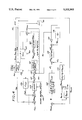
- FIG. 1 is a functional schematic diagram of a volume ventilator incorporating a flow control system in accordance with the present invention
- FIG. 2 is a functional schematic representation of the electro-pneumatic interface unit employed in the ventilator of FIG. 1;
- FIG. 3 is a semi-schematic representation of the flow control valve, the stepper motor that actuates the valve, and the circuitry that controls the motor, as used in the present invention.
- FIG. 4 is a schematic flow chart diagram showing the operation of the electronic control system microcomputer used to control the flow of inspiratory gas in the ventilator of FIG. 1.
- FIG. 1 A volume ventilator incorporating a preferred embodiment of the present invention is illustrated schematically in FIG. 1.
- the ventilator receives air and oxygen from pressurized supplies.
- the air and oxygen are filtered and regulated to 18 psig by conventional means, well-known in the art, illustrated schematically by a functional box 10, labeled "Inlet Pneumatics System".
- a description of a typical embodiment of the inlet pneumatics system is found in U.S. Pat. No. 4,527,557--DeVries et al., assigned to the assignee of the present application, the disclosure of which is incorporated herein by reference.
- the inlet pneumatics system 10 includes an air pressure tap 12 and an oxygen pressure tap 14, which lead, respectively, to an air pressure port 16 and an oxygen pressure port 18 of an electro-pneumatic interface (EPI) unit 20, to be described below.
- EPI electro-pneumatic interface
- the air and oxygen are fed to a blender 22, preferably of a type similar to that disclosed and claimed in U.S. Pat. No. 4,602,653--Ruiz-Vela et al., assigned to the assignee of the present application, the disclosure of which is incorporated herein by reference.
- the proportion of the oxygen in the blended gas may be varied between 21% and 100% by the blender 22, based on the oxygen percentage set on the control panel of the ventilator.
- An electronic control system (ECS) 23 converts the mechanical selection of the blend by the operator into an electrical signal, by conventional means, which signal is fed to the EPI unit, where it is conditioned and fed to the control mechanism for the blender 22.
- the air/oxygen mixture (which may now be referred to as "inspiratory gas”) is then fed into an accumulator 24.
- the inlet pneumatics system 10 also has a drive gas outlet 26, through which drive gas is provided for the operation of several ventilator subsystems, as will be discussed below.
- the drive gas is conducted through a shut-off system 28, described more fully below, which has a low pressure outlet 29 and a high pressure outlet 30.
- Drive gas from the low pressure outlet 29 is regulated to about 2 psig, while gas from the high pressure outlet 30 remains at approximately 18 psig.
- the major portion of the inspiratory gas is directed to a flow control valve 32, which will be described in detail below.
- a small portion of the accumulator outflow may optionally be tapped for direction to a conventional nebulizer system 34, which is controlled by a signal received from the EPI unit 20.
- the tapped flow from the nebulizer system 34 is directed to a nebulizer port 36.
- the major portion of the accumulator outflow is directed through the flow control valve 20, then through a subambient/overpressure relief ("SOPR") valve 38, to a patient outlet 40.
- SOPR subambient/overpressure relief
- the inspiratory gas is conducted to the patient through a conventional patient circuit (not shown), after passing through a bacterial filter (not shown) and an optional humidifier (not shown).
- the SOPR valve 38 performs a dual function: (1) It allows the patient to breathe ambient air in the event of ventilator failure; and (2) it acts as a relief valve to limit the maximum pressure delivered by the ventilator.
- the SOPR valve 38 has an inspiratory gas inlet port 41 that receives inspiratory gas from the flow control valve 32, and, in normal operation, passes the gas through to the patient outlet 40.
- the SOPR valve 38 has a first reference pressure inlet 42 that receives 2 psig drive gas pressure from the low pressure outlet 29 of the shut-off system 28.
- the 2 psig pressure acts as a reference pressure on one side of a spring-biased diaphragm (not shown), the other side of which is exposed to the gas flow received from the flow control valve.
- the diaphragm's pressure ratio is selected such that when the inspiratory gas pressure received from the flow control valve 32 exceeds about 175 cmH 2 O, the diaphragm opens an internal valve passage (not shown) from the inspiratory gas inlet port 41 to an overboard exhaust port 44, thereby relieving the excess pressure.
- the diaphragm opens under the force of its biasing spring (not shown), opening the above-mentioned internal passage to provide direct communication between the patient outlet 40 and the overboard exhaust port 44, thereby allowing the patient to inhale ambient air.
- the shut-off system 28 provides the 2 psig reference pressure to the SOPR valve 38 through the low pressure outlet 29. This reference pressure is also directed to a second reference pressure inlet port 46 in a PEEP/exhalation control subsystem 48.
- PEEP is an acronym for Positive End Expiratory Pressure.
- the PEEP/exhalation control subsystem 48 controls the operation of an exhalation valve 50, as will be described below.
- the 18 psig drive gas from the high pressure outlet 30 of the shut-off system is delivered to a high pressure inlet port 52 in the PEEP/exhalation control subsystem 48.
- the shut-off system 28, which is under the control of the EPI unit 20, includes a solenoid valve (not shown), having an inlet that receives drive gas from the inlet pneumatics system 10, and an outlet that communicates substantially directly with the high pressure outlet 30, and through a low pressure regulator (not shown) with the low pressure outlet 29.
- the solenoid is energized, passing 18 psig drive gas through to the high pressure outlet 30 and to the low pressure regulator, the latter dropping the pressure to 2 psig for passage through the low pressure outlet 29.
- shut-off system 28 If ventilator power is lost, the solenoid valve in the shut-off system 28 closes, cutting off drive gas to the PEEP/exhalation control subsystem 48, and thus depressurizing the exhalation valve 50. With no drive pressure applied to it, the exhalation valve 50 remains fully open, allowing the patient to exhale unimpeded. Closure of the shut-off system 28 also opens the passage in the SOPR valve 38 between the patient outlet 40 and the overboard exhaust port 44, as described above, thereby allowing unimpeded inhalation of ambient air.
- the PEEP/exhalation control subsystem 48 and the exhalation valve 50 are similar to those disclosed in the above-mentioned U.S. Pat. No. 4,527,557--DeVries et al., and thus only a brief description is needed here. The purpose of these components is twofold: (1) to close off the expiratory limb of the patient circuit during inhalation and open it during the exhalation; and (2) to maintain a selected PEEP level during exhalation.
- the exhalation valve 50 which is controlled by a signal from the EPI unit 20, also acts as a check valve, preventing inhalation through the expiratory leg of the patient circuit.
- the PEEP/exhalation control subsystem 48 includes a variable-orifice needle valve (not shown), the upstream side of which receives 18 psig drive gas from the high pressure outlet 30 of the shut-off system 30.
- a jet pump downstream from the needle valve, creates a static pressure that is applied to the ventilator side of the exhalation valve 50 to establish the PEEP.
- the level of PEEP is selected by varying the orifice of the needle valve by means of a PEEP adjustment control 54 on the control panel of the ventilator.
- exhalation flow transducer 58 preferably of the "hot wire" type.
- the exhalation flow transducer 58 generates an analog electrical output signal that is conditioned (i.e., digitized, amplified, and temperature-compensated) by associated flow transducer circuitry 59, before being fed into the EPI unit 20, which, in turn, produces an output signal directed to the ECS 23, which includes means (not shown) for integrating the signal over time to generate a visual display (not shown) of the exhalation volume.
- the EPI unit 20 is best understood with reference to FIG. 2.
- One major purpose of the EPI unit is to provide a clear interface between the ECS 23 and the pneumatic components of the ventilator. From the manual controls of the ECS 23, the EPI unit 20 receives signals representing the operator-selected values for the operational parameters, such as flow rate, oxygen concentration, and valve states. These signals are communicated to the EPI unit 20 every 10 milliseconds. Based on these signals, the EPI unit 20 commands the various valves (e.g., the blender 22, the flow control valve 32, and the PEEP/exhalation control subsystem 48) to assume their correct positions or states.
- the various valves e.g., the blender 22, the flow control valve 32, and the PEEP/exhalation control subsystem 48
- EPI unit 20 Another major function of the EPI unit 20 is to receive pneumatic and electrical signals representing pressures, temperatures, and flow rates within the ventilator, and to process these signals for use in controlling the ventilator, either automatically (i.e., by servo-control mechanisms), or manually (i.e., through the ECS 23).
- the EPI unit 20 includes several pneumatic input ports. Among these are the previously mentioned air pressure port 16 and the oxygen pressure port 18. Also included are a machine pressure port 60, a proximal pressure port 62, a PEEP port 64, and flow control valve pressure port 66.
- the machine pressure port 60 receives a static pressure from a machine pressure tap 68 at the downstream side of the SOPR valve 38.
- the proximal pressure port 62 receives a static pressure from a proximal pressure tap 70 on the ventilator side of the patient connector (not shown) that couples the patient to the patient circuit.
- the PEEP port 64 receives the PEEP from a PEEP tap 72 in the PEEP/exhalation control subsystem 48.
- the flow control valve pressure port 66 receives a static pressure from a flow control valve pressure tap 74 located on the upstream side of the flow control valve 32.
- the air pressure port 16, the oxygen pressure port 18, the machine pressure port 60, the proximal pressure port 62, and the flow control valve pressure port 66 each communicates with an associated miniature gage pressure transducer 80.
- the proximal pressure port 62 also communicates with one side of a miniature differential pressure transducer 82, the other side of which is in communication with the PEEP port 64.
- the transducers 80, 82 are preferably of a type marketed as the "16PC Series" by the Micro Switch Division of Honeywell, Inc. Transducers of this type are sensitive enough for the purposes of this invention, with a suitable pressure range, and yet are small enough for mounting on a printed circuit board 84 with the other electronic components, described below, of the EPI unit.
- Each of the gage transducers 80 produces an analog electrical output signal representing the value of the pressure applied to that transducer's associated port.
- the differential transducer 82 produces an analog electrical output signal representing the value of PEEP minus the proximal pressure; this differential signal may be termed "P DELTA ", and usually has a negative value.
- the analog signals are fed into an analog-to-digital converter (ADC) 86, which includes suitable amplification circuitry (not shown). After the signals are digitized and amplified, they are fed into a microcomputer 88, which also receives signals from the ECS 23, the blender 22 and the exhalation flow transducer circuitry 59.
- ADC analog-to-digital converter
- transducers 80 and 82 are mounted directly on the board 84, the transmission distances of their analog output signals to the ADC 86 are minimized, thereby rendering them less susceptible to noise (e.g., EMI) from external sources.
- Calibration factors for the pressure transducers 80, 82 are advantageously stored in an EEPROM 90 that is electronically coupled to the microcomputer 88.
- the microcomputer 88 may advantageously comprise a microcontroller (such as a Motorola 68HC05 microcontroller, or a substantial equivalent thereof) and a 4 MHz crystal, with the following on-chip functions: 176 bytes of random access memory (RAM), 7584 bytes of Read Only Memory (ROM), three 8-bit I/O ports, a serial peripheral interface port (for communication with the ADC 86 and the exhalation flow transducer circuitry 59), a serial communication interface port (for communicating with the ECS 23), and an 8-bit timer.
- a microcontroller such as a Motorola 68HC05 microcontroller, or a substantial equivalent thereof
- RAM random access memory
- ROM Read Only Memory
- serial peripheral interface port for communication with the ADC 86 and the exhalation flow transducer circuitry 59
- serial communication interface port for communicating with the ECS 23
- an 8-bit timer for communicating with the ECS 23
- Digital output signals from the microcomputer 88 are used to control the blender 22, the nebulizer system 34, the shut-off system 28, the PEEP/exhalation control subsystem 48, and the flow control valve 32, the control of the flow control valve being described in detail below.
- the air and oxygen pressure signals indicate proper operation of the inlet pneumatic system 10.
- An air or oxygen pressure below a predetermined threshold indicates a gas failure, as a result of which the microcomputer 88 is signaled to trigger an alarm (not shown) and to actuate the shut-off system 28, as described above, through a solenoid control circuit 92, of a type that is well-known in the art.
- the machine pressure signal represents the inspiratory gas pressure in the ventilator downstream from the flow control valve 32.
- the proximal pressure signal represents the pressure on the ventilator side of the patient connector. This signal is used, as will be explained below, to calculate the flow rate of inspiratory gas delivered to the patient through the flow control valve 32. It may also be used as an input signal to actuate a proximal pressure display, such as a gage 94 (FIG. 1) or an external pressure monitor (not shown).
- the flow control valve pressure signal represents the inspiratory gas pressure on the upstream side of the flow control valve 32. This signal is used, along with the proximal pressure signal, to calculate the flow rate through the flow control valve 32, as will be explained below.
- the P DELTA signal represents the difference between the PEEP and the proximal pressure. This signal is used as a feedback control signal for controlling the flow control valve 32 when the ventilator is in the pressure control, pressure support, or pressure augmentation mode, as will be explained below.
- the flow control valve 32 illustrated in FIG. 3, comprises a housing 100 having a gas inlet 102 that receives inspiratory gas from the accumulator 24, and a gas outlet 104 that delivers the gas to the SOPR valve 38. Between the inlet 102 and the outlet 104 is a valve seat 106 defining a valve orifice 108, the effective flow area of which is varied by a poppet valve element 110, preferably spherical in form, as shown. The position of the valve element 110 relative to the valve seat 106, and thus the effective flow area of the valve orifice 108, is controlled by a rod 112 that is journaled, by suitable bearings (not shown), for axial movement within the valve housing 100.
- One end of the rod 112 engages the valve element 110, while the other end is engaged by an asymmetrical cam 114 that is mounted on a shaft 116 of a stepper motor 118.
- the rod 112 is advantageously maintained in engagement with the cam 114 by a coil spring 120.
- the flow control valve 32 is similar to the flow control valve disclosed in the above-mentioned U.S. Pat. No. 4,527,557--DeVries, except that in the prior art valve, the valve element seats against the downstream side of the flow orifice, while in the flow control valve 32 employed in the present invention, the valve element 110 seats against the upstream side of the orifice 108.
- the flow control valve 32 of the present invention uses the spring 120 to assure that the rod 112 follows the cam 114, while the prior art device uses gas pressure for this purpose. It should be noted that a flow control valve of the type disclosed in the DeVries patent can be used in a flow control system in accordance with the present invention, without departing from the spirit and scope of the invention.
- the valve housing 100 contains temperature sensing means, such as a thermistor 122, downstream from the valve orifice 108.
- the thermistor 122 generates an analog electrical signal representing the temperature of the inspiratory gas, and this signal is then inputted to the EPI unit 20, and, more specifically, to the ADC 86.
- the stepper motor 118 is a unipolar, four-phase motor, with a resolution of at least about 0.9 degrees of rotation per half step, and an effective rotational speed of approximately 1100 half steps per second.
- the motor 118 drives the valve element 110 between a fully closed position (corresponding to zero half steps of the motor) and a fully open position (corresponding to between 112 and 119 half steps of the motor, or approximately 101 to 107 degrees of rotation of the shaft 116.
- the zero flow (fully closed) position and the full flow (fully open) position are the end limits of rotational movement of the motor, as determined by an optical encoder element 124 that is coupled to the shaft 116, and that is configured to interrupt a light beam (not shown) at the above-mentioned limits of rotational travel.
- the light beam may be transmitted from optical emission means, such as an LED 126, to a photodetector 128. Interruption of the beam thus causes the photodetector 128 to generate an "end stop" signal, represented schematically in FIG. 3 by a functional box 130, labeled "End Stops".
- stepper motor 118 The motion of the stepper motor 118, and thus the position of the flow control valve element 110, is controlled by an electronic valve actuation subsystem 132 in the following manner:
- a "position-to-area" look-up table of values representing the effective flow orifice area as a function of the angular position of the stepper motor shaft 116 (in terms of the number of stepper motor half steps from the zero end stop) is stored in a flow control EEPROM 134, which is preferably a 256 ⁇ 8 bit device, such as a XICOR model X2402.
- the number of half steps that the motor 118 has stepped through from the zero end stop is determined by a second microcomputer (described below) in the ECS 23, and transmitted to the EPI microcomputer 88.
- a programmable array logic device 136 (such as the device marketed by Advanced Micro Devices under the trademark (“PAL16R4", or the substantial equivalent thereof) generates a control signal for controlling the motor 118 in response to signals received from the microcomputer 88 and the end stop mechanism 130.
- This motor control signal is inputted to a motor phase controller 138 (such as the SGS Model L6506 current controller, or the substantial equivalent thereof), which provides pulse width modulation current regulation to the motor 118 to move it the appropriate number of steps in the appropriate direction.
- the half step number determined by the ECS microcomputer is used in the position-to-area look-up table stored in the flow control EEPROM 134 to determine the effective flow orifice area corresponding to that half step number from the look-up table stored therein.
- the looked-up flow orifice area value is then temporarily stored in the microcomputer's RAM.
- the position-to-area look-up table in the EEPROM 134 is unique to each flow control valve and its associated stepper motor.
- the PC board on which the EEPROM 134 is mounted is physically attached to the valve/stepper motor assembly, and the EEPROM is loaded with a look-up table that is empirically derived for the valve/motor assembly to which it is attached.
- each valve is pre-calibrated during manufacture by the loading of its unique look-up table, and no further calibration is necessary. Should the valve and/or motor later need to be replaced, a new valve/motor/PC board assembly is installed, already calibrated by the loading of the look-up table.
- the ECS microcomputer comprises an Intel 80188 NMOS microcontroller and a 20 MHz crystal oscillator, with the following on-chip functions: three 16-bit counter/timers, two DMA channels, an interrupt controller, a clock generator, and programmable memory/peripheral chip select logic.
- the ECS microcomputer also includes an 8K ⁇ 8 CMOS static RAM, a 64K ⁇ 8 EPROM (containing the control software), and three 10-bit digital-to-analog converters (DACs) (for outputting analog flow rate, volume and pressure signals in real time).
- DACs digital-to-analog converters
- the EPROM of the ECS microcomputer has stored within it a set of algorithms for calculating an instantaneous actual ("real time") volumetric flow rate value for the "delivered” flow through the flow control valve 32.
- the algorithms in essence, solve the following equation for the actual volumetric "delivered" flow rate F, with standard temperature, ambient pressure correction: ##EQU1## where A is the effective flow orifice area, RKT is a correction factor that is a function of the oxygen concentration, P 1 is the pressure upstream from the flow control valve (flow control valve pressure), P 2 is the pressure downstream from the flow control valve (proximal pressure), T gas is the inspiratory gas temperature in the flow control valve (measured on the Rankine scale), N is a weighted flow ratio (which is a function of the ratio of P 2 to P 1 ), and P atm is atmospheric pressure (which may be selected by the operator to approximate the average barometric pressure of the geographic location of the ventilator).
- the values of the correction factor RKT as a function of the percentage of oxygen in the inspiratory gas blend (21% to 100%) are contained in a look-up table stored in the ECS unit EPROM.
- the values for RKT are derived from the following equation:
- T a is an assumed value for ambient temperature, namely 537° R, 0.9833 is a conversion constant to convert the units of the RKT factor to liters per minute (lpm)
- R and K are gas factors that are derived from the following equations: ##EQU2## where Vf a is a fraction indicating the proportion of air in the blended mixture, varying from 0 (pure oxygen) to 1 (pure air); Vf o is a fraction indicating the proportion of oxygen in the mixture, varying from 1 (pure oxygen) to 0 (pure air); M a is a constant indicating the average molecular mass of normal ambient air (28.96); M o is a constant indicating the molecular mass of oxygen (32.00); R a and K a are empirically derived gas constants for air; and R o and K o are analogous, empirically derived gas constants for oxygen.
- the parameter M is the average molecular mass of the gas mixture, and its value is obtained from the following equation:
- N is contained in a look-up table stored in the ECS unit EPROM. These values are derived from the following equation:
- G1, G2, and G3 are empirically derived constants having the approximate values of 1.429, 1.714, and 0.067, respectively.
- the value for proximal pressure is derived from the gage pressure transducer 80 associated with the proximal pressure port 62 in the EPI unit 20.
- the flow control valve pressure value is derived from the gage pressure transducer 80 associated with the flow control valve pressure port 66 in the EPI unit 20.
- signals representing these pressure values are transmitted by the transducers to the microcomputer 88, after conditioning by the ADC 86.
- the inspiratory gas temperature T gas is represented by a temperature signal received by the microcomputer 88 from the thermistor 122 in the flow control valve 32, after this temperature signal has been conditioned by the ADC 86.
- the calculated volumetric flow rate value (the "flow signal") is compared, in logic circuitry contained in the ECS 23, with a desired flow rate value ("volume input signal”), based on the control settings selected by the operator (either directly, or as a function of other parameters).
- the comparison yields a difference or correction signal.
- This correction signal is used to generate a flow control valve position signal which is eventually supplied as a pulse train to the programmable array logic device 136.
- the pulse train determines the number of half steps the motor must turn, and a directional bit is included to control the direction of rotation.
- the programmable array logic device 136 In response to the pulse train, the programmable array logic device 136 generates a motor control signal for the stepper motor 118, whereby the motor is actuated to drive the valve element 110 to a position that provides a flow rate substantially equal to the desired flow rate.
- a desired volume input signal F vol is generated in the ECS 23, in response to the operator's selection (via manual controls) of such respiratory parameters as end tidal volume, breath rate, inspiratory waveform, and the ratio of inspiratory time to expiratory time (I:E ratio).
- This F vol signal is the input signal to a volume control system 150, in which it is algebraically summed with an inverted delivered flow signal F del , which, as will be explained below, indicates the actual instantaneous volumetric flow rate through the flow control valve 32.
- F vol The difference between F vol and F del is a flow correction signal dF vol , which is summed with a previously stored flow reference signal value F' ref , the derivation of which will be made clear below. This sum yields an intermediate volume reference signal F i .
- the circuitry of FIG. 4 is designed to correct the position of the flow control valve 32 every 10 milliseconds.
- the stepper motor 118 has an effective rotational speed of about 1100 half steps per second. Therefore, the stepper motor can be expected to rotate no more than 11 half steps during each valve position correction cycle.
- a first limiting algorithm 152 is provided that receives the intermediate volume reference signal F i and a current valve position signal V pos .
- the first limiting algorithm 152 determines upper and lower flow rate limits that would require the stepper motor to rotate 11 half steps in either direction from its current position, as indicated by the value of V pos .
- the first limiting algorithm 152 then compares the value of F i with the upper and lower flow rate limits.
- the first limiting algorithm 152 outputs the actual F i value as a volume reference signal F vr . If the value is above the upper limit, the first limiting algorithm outputs a F vr value that is equal to the upper limit. If the inputted F i value is below the lower limit, the output is equal to the lower limit.
- a flow control enable switch 153 is turned “ON".
- the volume reference signal F vr is then inputted to a comparator 154, the purpose of which will be explained below.
- the output of the comparator 154 is a flow reference signal F ref .
- the value of F ref is then stored in a first random access memory (RAM) sector 156, so that its immediately preceding value F' ref can be summed with the flow correction signal dF vol to produce the intermediate volume reference signal F i , as described above.
- the flow reference signal F ref is then inputted to a flow-to-position subsystem 158, in which it is used to address a flow-to-position look-up table 160, stored in the ECS EPROM.
- the flow-to-position look-up table 160 contains values for stepper motor positions corresponding to each increment of the flow rate reference signal F ref , based on predetermined conditions, and thereby produces as its output a flow control valve position reference signal V ref .
- the position reference signal V ref is algebraically summed with an inverted, previously stored position signal value V' pos , the derivation of which will be made clear below, to yield a position error signal dV pos .
- This signal is then inputted to a second limiter circuit 162, which limits the value of the position error signal dV pos to one that will not drive the stepper motor 118 more than 11 half steps in either direction from its current position.
- the position error signal dV pos is then algebraically summed with the valve position signal V' pos .
- the resulting value is the current value position signal V pos , which is stored in a second RAM sector 164, from which the value V' pos is generated for inversion and summing with the position reference signal V ref to produce the position error signal dV pos , as described above.
- a look-up table of flow orifice area values as a function of stepper motor position (number of steps from the zero end stop) is stored in the EEPROM 134 associated with the flow control valve 32 (FIG. 3).
- This look-up table may be called a "position-to-area" look-up table, and it is represented in FIG. 4 by a functional box 166.
- the ECS microcomputer addresses the position-to-area look-up table 166 to read the effective orifice area value A corresponding to the value of the position signal V pos .
- This value is then used by the microcomputer to calculate the actual flow rate through the flow control valve 32, using Equation (1) above, with values for RKT, N, P 1 ,T gas , and P atm either inputted or read from look-up tables, as described above.
- This calculated flow rate value is outputted as the delivered flow rate signal F del .
- the current valve position signal value V pos is transmitted to the EPI microcomputer 88 which, in turn, pulses the programmable array logic device 136 as described above.
- the programmable array logic device In response to these signal values, the programmable array logic device generates the motor control signal that causes the stepper motor to rotate the appropriate number of half steps (not more than 11) in the appropriate direction, corresponding to the difference between V pos and V' pos .
- the stepper motor is moving the valve element 110, and thus changing the effective flow orifice area
- the valve position signal is conveyed to and converted by the position-to-area look-up table 166 to the effective orifice value A.
- the ventilator is also capable of operation in pressure support and pressure control modes.
- the operator inputs a selected pressure value P input , representing a desired inspiratory pressure.
- the P input value is summed with a value for P delta obtained from the EPI, as described above.
- the resulting sum is a pressure error signal P E .
- the pressure error signal P E is processed, in the ECS microcomputer, using an algorithm in which the value of P E is multiplied by one of three factors, as follows: If the value of P E is positive, the multiplier is the operator-selected slope of the inspiratory pressure, represented in a functional box 168 in FIG. 4 by the symbol K 1 .
- K 1 is the slope of an inspiratory pressure-versus-time curve selected by the operator by means of a control on the ECS. If the value of P E is zero or negative, then the multiplier is a constant K 2 , having a value of 1.5 for adult patients, and 0.5 for pediatric patients. The appropriate value for K 2 is determined by an operator-actuated control in the ECS that provides for selecting either an "adult" mode or a "pediatric" mode. The result of this multiplication is a first flow correction signal dF i .
- the present value of the P delta signal is algebraically summed with an inverted, immediately preceding value P' delta , stored in a third RAM sector 170.
- the resulting sum is a P delta correction signal dP delta , which is then multiplied by a constant factor K D , as illustrated in a function box 172.
- the factor K D is either 3 for an adult patient, or 1 for a pediatric patient, as selected by the operator.
- the result of this multiplication is a second flow correction signal dF D .
- the first flow correction signal dF i and the second flow correction signal dF D are algebraically summed, and the resulting sum dF iD is then operated on by a third limiting algorithm 174.
- the purpose of the third limiting algorithm 174 is to limit the correction signal so that its value is such as to cause the stepper motor to be driven not more than 11 half steps in either direction.
- the resulting limited flow correction signal dF L is used to generate a pressure control signal F pr by algebraically summing the limited flow correction signal dF L with the immediately preceding value F' pr of the pressure control signal, stored in a fourth RAM sector 176.
- the volume control enable switch 153 is turned “OFF”, and a pressure control enable switch 178 is turned “ON”. This enables the pressure control signal F pr to address the flow-to-position table 160 as the flow reference signal F ref , after passing through the comparator 154. Actuation of the flow control valve 32 then proceeds as described above in connection with the volume control mode.
- the flow reference signal F ref is derived from the operator-selected inspiratory pressure value P input , rather than from volume input signal F vol , based on the operator-selected volumetric parameters used in the volume control mode.
- the above described flow control mechanism allows for still another mode of ventilator operation, which may be termed the "pressure augmentation" mode.
- the pressure augmentation mode both the volume control enable switch 153 and the pressure control enable switch 178 are turned “ON”.
- the comparator 154 receives both the volume control signal F vr and the pressure control signal F pr .
- the comparator 154 determines which of these two signals has the larger value, and only the larger of the two is passed to the flow-to-position subsystem 158 for actuation of the flow control valve 32.
- the operator can select a desired inspiratory pressure level P input , a minimum end tidal volume, and a desired flow rate value F vol .
- the pressure control signal value F pr is normally greater than the volume control signal value F vr .
- the patient can be ventilated essentially in the pressure control mode or pressure support mode. If, however, the actual inspiratory pressure exceeds the value of P input (due to reduced patient demand, increased airway resistance, or decreased lung compliance), the control signal F vr will become dominant, and then actuate the flow control valve so as to provide the flow rate required to achieve the selected end tidal volume.
- the patient is assured of receiving the operator-selected minimum end tidal volume.
- the pressure control signal F pr will dominate, thereby actuating the flow control valve so as to provide the flow rate required to achieve the end tidal volume actually demanded by the patient.
- the subject invention provides a flow control system including a method for controlling the flow of gas that is particularly responsive to the input signal to the system.
- This input may be based on desired flow rate or desired effective pressure or the greater of the two.
- the equations disclosed and the factors used in processing the signals are those used in the preferred embodiment as used in a ventilator using the apparatus disclosed.
- valve reference signal is formed from the flow reference signal based on a predetermined relationship using a look up table
- this predetermined relationship could alternatively be implemented by a microprocessor using the flow control valve pressure, the proximal airway pressure and an accurate relationship between position and orifice area.
Abstract
Description
RKT=R*K*T.sub.a *0.9833 (2)
M=(Vf.sub.o *M.sub.o)+(Vf.sub.a *M.sub.a) (5)
N=[(P.sub.2 /P.sub.1).sup.G1 /G3-(P.sub.2 /P.sub.1).sup.G2 /G3].sup.1/2(6)
Claims (22)
Priority Applications (1)
| Application Number | Priority Date | Filing Date | Title |
|---|---|---|---|
| US07/916,344 US5331995A (en) | 1992-07-17 | 1992-07-17 | Flow control system for medical ventilator |
Applications Claiming Priority (1)
| Application Number | Priority Date | Filing Date | Title |
|---|---|---|---|
| US07/916,344 US5331995A (en) | 1992-07-17 | 1992-07-17 | Flow control system for medical ventilator |
Publications (1)
| Publication Number | Publication Date |
|---|---|
| US5331995A true US5331995A (en) | 1994-07-26 |
Family
ID=25437113
Family Applications (1)
| Application Number | Title | Priority Date | Filing Date |
|---|---|---|---|
| US07/916,344 Expired - Fee Related US5331995A (en) | 1992-07-17 | 1992-07-17 | Flow control system for medical ventilator |
Country Status (1)
| Country | Link |
|---|---|
| US (1) | US5331995A (en) |
Cited By (122)
| Publication number | Priority date | Publication date | Assignee | Title |
|---|---|---|---|---|
| EP0896660A1 (en) * | 1996-05-03 | 1999-02-17 | H.K. Medical Technologies Incorporated | Automatic valve test apparatus |
| US5918597A (en) * | 1998-01-15 | 1999-07-06 | Nellcor Puritan Bennett | Peep control in a piston ventilator |
| US5931160A (en) * | 1995-12-08 | 1999-08-03 | Cardiopulmonary Corporation | Ventilator control system and method |
| US5963883A (en) * | 1997-04-09 | 1999-10-05 | Westinghouse Air Brake Company | Modified airflow algorithm with compensation for variations in main reservoir air pressure and ambient airflow |
| US6016832A (en) * | 1997-04-16 | 2000-01-25 | Woodward Governor Company | Valve for controlling gas mass flow |
| WO2000023134A1 (en) * | 1998-10-21 | 2000-04-27 | Airsep Corporation | Combined oxygen regulator and conservation device |
| WO2000032261A1 (en) * | 1998-12-04 | 2000-06-08 | Bunnel, Incorporated | Variable flow and pressure ventilation system |
| US6076523A (en) * | 1998-01-15 | 2000-06-20 | Nellcor Puritan Bennett | Oxygen blending in a piston ventilator |
| EP1045712A1 (en) * | 1998-10-23 | 2000-10-25 | Pulmonetic Systems, Inc. | Ventilator system |
| US6158432A (en) * | 1995-12-08 | 2000-12-12 | Cardiopulmonary Corporation | Ventilator control system and method |
| US6349722B1 (en) * | 1997-06-17 | 2002-02-26 | Fisher & Paykel Limited | Respiratory humidification system |
| US6378520B1 (en) * | 1999-10-29 | 2002-04-30 | Salter Labs | Variable pressure and flow control for a pneumatically-operated gas demand apparatus |
| US6390091B1 (en) | 1999-02-03 | 2002-05-21 | University Of Florida | Method and apparatus for controlling a medical ventilator |
| US6463930B2 (en) | 1995-12-08 | 2002-10-15 | James W. Biondi | System for automatically weaning a patient from a ventilator, and method thereof |
| US20020192831A1 (en) * | 2001-04-06 | 2002-12-19 | Jacques Fournier | Method of controlling the hydrocarbon content of a vapor circulating in an installation fitted with a vapor intake system |
| US6553992B1 (en) * | 2000-03-03 | 2003-04-29 | Resmed Ltd. | Adjustment of ventilator pressure-time profile to balance comfort and effectiveness |
| US6557574B2 (en) | 2000-04-04 | 2003-05-06 | Clifford C. Federspiel | Pressure based flow rate measurement device integrated with blades of a damper |
| US6571796B2 (en) | 2001-02-08 | 2003-06-03 | University Of Florida | Tracheal pressure ventilation respiratory system |
| US20040003813A1 (en) * | 1999-06-30 | 2004-01-08 | Banner Michael J. | Medical ventilator and method of controlling same |
| US20040035413A1 (en) * | 2002-05-07 | 2004-02-26 | The Research Foundation | Methods, devices and formulations for targeted endobronchial therapy |
| WO2004046840A1 (en) * | 2002-11-20 | 2004-06-03 | Air Products And Chemicals, Inc. | Volume flow controller |
| US20040199476A1 (en) * | 2001-03-22 | 2004-10-07 | Fernando Milanes Garcia-Moreno | Electronic and mechanical system for automated or discretionay dosage of potable water at the particular intake level of each user |
| US20040221844A1 (en) * | 1997-06-17 | 2004-11-11 | Hunt Peter John | Humidity controller |
| US20040250856A1 (en) * | 2003-06-13 | 2004-12-16 | Mcmillan Robert M. | Flow system with high resolution proportional valve with customizable performance |
| US20050051215A1 (en) * | 2003-09-04 | 2005-03-10 | Nugent Dale Alan | Apparatus for controlling and metering fluid flow |
| US6892726B1 (en) | 1998-12-08 | 2005-05-17 | Instrumentarium Corp. | Arrangement in connection with equipment used in patient care |
| US20050121035A1 (en) * | 2001-10-19 | 2005-06-09 | Jan Martin | Respiratory apparatus for compressed-air breathing equipment |
| US20050192538A1 (en) * | 2004-02-26 | 2005-09-01 | Voege James A. | Method and apparatus for regulating fluid flow or conserving fluid flow |
| US20050235987A1 (en) * | 2002-05-06 | 2005-10-27 | The Research Foundation Of State University Of New York | Methods, devices and formulations for targeted endobronchial therapy |
| US20060042240A1 (en) * | 2004-08-30 | 2006-03-02 | Caterpillar S.A.R.L. | System and method for controlling hydraulic fluid flow |
| US20070000494A1 (en) * | 1999-06-30 | 2007-01-04 | Banner Michael J | Ventilator monitor system and method of using same |
| WO2007045036A1 (en) * | 2005-10-21 | 2007-04-26 | Resmed Ltd | Method and apparatus for improving flow and pressure estimation in cpap systems |
| US20070157930A1 (en) * | 2006-01-10 | 2007-07-12 | Viasys Manufacturing, Inc. | System and method for circuit compliance compensated volume assured pressure control in a patient respiratory ventilator |
| US7290544B1 (en) * | 1998-12-08 | 2007-11-06 | Ge Healthcare Finland Oy | Arrangement in connection with feedback control system |
| WO2007141386A1 (en) * | 2006-06-06 | 2007-12-13 | Metso Automation Oy | Control method and control system for a flow control valve |
| US20080029088A1 (en) * | 2006-05-18 | 2008-02-07 | Breathe Technologies, Inc. | Tracheostoma spacer, tracheotomy method, and device for inserting a tracheostoma spacer |
| US20080105317A1 (en) * | 2006-11-02 | 2008-05-08 | Rivatek, Inc. | Fluid flow blender and methods |
| US20080105259A1 (en) * | 2001-11-30 | 2008-05-08 | Viasys Healthcare, Critical Care Division | Gas identification system and respiratory technologies volumetrically corrected gas delivery system |
| WO2008019102A3 (en) * | 2006-08-03 | 2008-07-03 | Breathe Technologies Inc | Methods and devices for minimally invasive respiratory support |
| US20080230062A1 (en) * | 2007-03-23 | 2008-09-25 | General Electric Company | Setting expiratory time in mandatory mechanical ventilation based on a deviation from a stable condition of exhaled gas volumes |
| US20080276939A1 (en) * | 2004-07-08 | 2008-11-13 | Breas Medical Ab | Delta Flow Pressure Regulation |
| WO2008147229A1 (en) * | 2007-05-30 | 2008-12-04 | Gilbert Jacobus Kuypers | Improvements to electrically operable resuscitators |
| US7487778B2 (en) | 2003-08-11 | 2009-02-10 | Breathe Technologies, Inc. | Tracheal catheter and prosthesis and method of respiratory support of a patient |
| US20090065081A1 (en) * | 2007-09-12 | 2009-03-12 | Paul Luebbers | Dynamic Orifice Valve Apparatus And Method |
| US20090114861A1 (en) * | 2007-09-12 | 2009-05-07 | Paul Luebbers | Control system for dynamic orifice valve apparatus and method |
| US7533670B1 (en) | 2005-09-20 | 2009-05-19 | Breathe Technologies, Inc. | Systems, methods and apparatus for respiratory support of a patient |
| US20090165798A1 (en) * | 2007-12-28 | 2009-07-02 | Beijing Aeonmed Co., Ltd. | method for improving control and detection precision of tidal volume by a calculation introduced with r value |
| AU2003303914B2 (en) * | 2002-05-07 | 2009-08-06 | The Research Foundation Of State University Of New York | Methods, devices and formulations for targeted endobronchial therapy |
| US20090199855A1 (en) * | 2004-11-01 | 2009-08-13 | Davenport James M | System and method for conserving oxygen delivery while maintaining saturation |
| WO2009110895A1 (en) * | 2008-03-05 | 2009-09-11 | Brooks Instrument, Llc | A system, method, and computer program for determining fluid flow rate using a pressure sensor and a thermal mass flow sensor |
| US7588033B2 (en) | 2003-06-18 | 2009-09-15 | Breathe Technologies, Inc. | Methods, systems and devices for improving ventilation in a lung area |
| US20100147394A1 (en) * | 2008-12-16 | 2010-06-17 | Honeywell International Inc. | System and method for decentralized balancing of hydronic networks |
| US20100308241A1 (en) * | 2006-03-03 | 2010-12-09 | Kevin Doyle | Electronically controlled valve actuator in a pool or spa water line system |
| US20100323064A1 (en) * | 2007-02-16 | 2010-12-23 | Snow Brand Milk Products Co., Ltd. | Agent For Improving Viability of Lactic Acid Bacteria |
| WO2011068771A1 (en) * | 2009-12-03 | 2011-06-09 | Nellcor Puritan Bennett Llc | Ventilator respiratory gas accumulator with purge valve |
| US20110192600A1 (en) * | 2010-02-10 | 2011-08-11 | Bruce Patterson | Precision low flow rate fluid delivery system and methods for controlling same |
| USD653749S1 (en) | 2010-04-27 | 2012-02-07 | Nellcor Puritan Bennett Llc | Exhalation module filter body |
| USD655405S1 (en) | 2010-04-27 | 2012-03-06 | Nellcor Puritan Bennett Llc | Filter and valve body for an exhalation module |
| USD655809S1 (en) | 2010-04-27 | 2012-03-13 | Nellcor Puritan Bennett Llc | Valve body with integral flow meter for an exhalation module |
| US8136527B2 (en) | 2003-08-18 | 2012-03-20 | Breathe Technologies, Inc. | Method and device for non-invasive ventilation with nasal interface |
| US8230859B1 (en) | 2004-02-26 | 2012-07-31 | Ameriflo, Inc. | Method and apparatus for regulating fluid |
| US8434479B2 (en) | 2009-02-27 | 2013-05-07 | Covidien Lp | Flow rate compensation for transient thermal response of hot-wire anemometers |
| US8439036B2 (en) | 2009-12-01 | 2013-05-14 | Covidien Lp | Exhalation valve assembly with integral flow sensor |
| US8439037B2 (en) | 2009-12-01 | 2013-05-14 | Covidien Lp | Exhalation valve assembly with integrated filter and flow sensor |
| US8457706B2 (en) | 2008-05-16 | 2013-06-04 | Covidien Lp | Estimation of a physiological parameter using a neural network |
| US8469031B2 (en) | 2009-12-01 | 2013-06-25 | Covidien Lp | Exhalation valve assembly with integrated filter |
| US8469030B2 (en) | 2009-12-01 | 2013-06-25 | Covidien Lp | Exhalation valve assembly with selectable contagious/non-contagious latch |
| US8567399B2 (en) | 2007-09-26 | 2013-10-29 | Breathe Technologies, Inc. | Methods and devices for providing inspiratory and expiratory flow relief during ventilation therapy |
| USD692556S1 (en) | 2013-03-08 | 2013-10-29 | Covidien Lp | Expiratory filter body of an exhalation module |
| USD693001S1 (en) | 2013-03-08 | 2013-11-05 | Covidien Lp | Neonate expiratory filter assembly of an exhalation module |
| US20130312754A1 (en) * | 2010-12-17 | 2013-11-28 | Koninklijke Philips Electronics N.V. | System and method for customizable automated control of fraction of inspired oxygen and/or positive end expiratory pressure to maintain oxygenation |
| US20140069516A1 (en) * | 2011-02-28 | 2014-03-13 | Smartap A.Y Ltd | Household Electronic Mixing-Valve Device |
| US8677999B2 (en) | 2008-08-22 | 2014-03-25 | Breathe Technologies, Inc. | Methods and devices for providing mechanical ventilation with an open airway interface |
| USD701601S1 (en) | 2013-03-08 | 2014-03-25 | Covidien Lp | Condensate vial of an exhalation module |
| US8770193B2 (en) | 2008-04-18 | 2014-07-08 | Breathe Technologies, Inc. | Methods and devices for sensing respiration and controlling ventilator functions |
| CN103908724A (en) * | 2012-12-29 | 2014-07-09 | 北京谊安医疗系统股份有限公司 | Method, device and system for aging flow valve |
| US8776793B2 (en) | 2008-04-18 | 2014-07-15 | Breathe Technologies, Inc. | Methods and devices for sensing respiration and controlling ventilator functions |
| US8800557B2 (en) | 2003-07-29 | 2014-08-12 | Covidien Lp | System and process for supplying respiratory gas under pressure or volumetrically |
| US20150000664A1 (en) * | 2013-06-28 | 2015-01-01 | Carefusion 303, Inc. | Modular flow cassette |
| US8925545B2 (en) | 2004-02-04 | 2015-01-06 | Breathe Technologies, Inc. | Methods and devices for treating sleep apnea |
| US8939152B2 (en) | 2010-09-30 | 2015-01-27 | Breathe Technologies, Inc. | Methods, systems and devices for humidifying a respiratory tract |
| USD731049S1 (en) | 2013-03-05 | 2015-06-02 | Covidien Lp | EVQ housing of an exhalation module |
| USD731048S1 (en) | 2013-03-08 | 2015-06-02 | Covidien Lp | EVQ diaphragm of an exhalation module |
| USD731065S1 (en) | 2013-03-08 | 2015-06-02 | Covidien Lp | EVQ pressure sensor filter of an exhalation module |
| USD736905S1 (en) | 2013-03-08 | 2015-08-18 | Covidien Lp | Exhalation module EVQ housing |
| US9132250B2 (en) | 2009-09-03 | 2015-09-15 | Breathe Technologies, Inc. | Methods, systems and devices for non-invasive ventilation including a non-sealing ventilation interface with an entrainment port and/or pressure feature |
| US9144658B2 (en) | 2012-04-30 | 2015-09-29 | Covidien Lp | Minimizing imposed expiratory resistance of mechanical ventilator by optimizing exhalation valve control |
| US9175786B2 (en) | 2013-08-30 | 2015-11-03 | Lumec Control Products, Inc. | Valve apparatus |
| US9180270B2 (en) | 2009-04-02 | 2015-11-10 | Breathe Technologies, Inc. | Methods, systems and devices for non-invasive open ventilation with gas delivery nozzles within an outer tube |
| USD744095S1 (en) | 2013-03-08 | 2015-11-24 | Covidien Lp | Exhalation module EVQ internal flow sensor |
| US20160022934A1 (en) * | 2006-06-07 | 2016-01-28 | Carefusion 207, Inc. | System and method for adaptive high frequency flow interrupter control in a patient respiratory ventilator |
| US20160074608A1 (en) * | 2007-11-16 | 2016-03-17 | Fisher & Paykel Healthcare Limited | Nasal pillows with high volume bypass flow and method of using same |
| US20160121071A1 (en) * | 2014-10-30 | 2016-05-05 | Nu-Med Plus | Controlled delivery of medical gases using diffusion membranes |
| US9364624B2 (en) | 2011-12-07 | 2016-06-14 | Covidien Lp | Methods and systems for adaptive base flow |
| US9433743B2 (en) | 2013-06-28 | 2016-09-06 | Carefusion 303, Inc. | Ventilator exhalation flow valve |
| WO2016168545A1 (en) * | 2015-04-15 | 2016-10-20 | University Of Delaware | Devices, systems, and methods for variable flow rate fuel ejection |
| US9498589B2 (en) | 2011-12-31 | 2016-11-22 | Covidien Lp | Methods and systems for adaptive base flow and leak compensation |
| USD775345S1 (en) | 2015-04-10 | 2016-12-27 | Covidien Lp | Ventilator console |
| US9541098B2 (en) | 2013-06-28 | 2017-01-10 | Vyaire Medical Capital Llc | Low-noise blower |
| US9629971B2 (en) | 2011-04-29 | 2017-04-25 | Covidien Lp | Methods and systems for exhalation control and trajectory optimization |
| US9649458B2 (en) | 2008-09-30 | 2017-05-16 | Covidien Lp | Breathing assistance system with multiple pressure sensors |
| CN107014444A (en) * | 2017-05-27 | 2017-08-04 | 山东罗泰风机有限公司 | A kind of blower fan dynamic performance parameter measuring system |
| US9746359B2 (en) | 2013-06-28 | 2017-08-29 | Vyaire Medical Capital Llc | Flow sensor |
| US9795757B2 (en) | 2013-06-28 | 2017-10-24 | Vyaire Medical Capital Llc | Fluid inlet adapter |
| US9950135B2 (en) | 2013-03-15 | 2018-04-24 | Covidien Lp | Maintaining an exhalation valve sensor assembly |
| US9956371B2 (en) | 2015-03-24 | 2018-05-01 | Ventec Life Systems, Inc. | Ventilator with integrated cough-assist |
| US9962514B2 (en) | 2013-06-28 | 2018-05-08 | Vyaire Medical Capital Llc | Ventilator flow valve |
| US9962512B2 (en) | 2009-04-02 | 2018-05-08 | Breathe Technologies, Inc. | Methods, systems and devices for non-invasive ventilation including a non-sealing ventilation interface with a free space nozzle feature |
| EP3320939A4 (en) * | 2015-07-14 | 2018-07-25 | Beijing Aeonmed Co., Ltd. | Closed loop capacity control method for respirator |
| US10058668B2 (en) | 2007-05-18 | 2018-08-28 | Breathe Technologies, Inc. | Methods and devices for sensing respiration and providing ventilation therapy |
| US10099028B2 (en) | 2010-08-16 | 2018-10-16 | Breathe Technologies, Inc. | Methods, systems and devices using LOX to provide ventilatory support |
| US10130787B2 (en) | 1997-06-17 | 2018-11-20 | Fisher & Paykel Healthcare Limited | Humidity controller |
| US10252020B2 (en) | 2008-10-01 | 2019-04-09 | Breathe Technologies, Inc. | Ventilator with biofeedback monitoring and control for improving patient activity and health |
| CN110801563A (en) * | 2019-11-05 | 2020-02-18 | 塔城市人民医院 | Respirator and automatic calibration method for oxygen sensor of respirator |
| US10773049B2 (en) | 2016-06-21 | 2020-09-15 | Ventec Life Systems, Inc. | Cough-assist systems with humidifier bypass |
| CN111701121A (en) * | 2020-06-10 | 2020-09-25 | 吉林大学第一医院 | ICU assisted respiration device with adjustable |
| US10792449B2 (en) | 2017-10-03 | 2020-10-06 | Breathe Technologies, Inc. | Patient interface with integrated jet pump |
| US11154672B2 (en) | 2009-09-03 | 2021-10-26 | Breathe Technologies, Inc. | Methods, systems and devices for non-invasive ventilation including a non-sealing ventilation interface with an entrainment port and/or pressure feature |
| US11191915B2 (en) | 2018-05-13 | 2021-12-07 | Ventec Life Systems, Inc. | Portable medical ventilator system using portable oxygen concentrators |
| US11247015B2 (en) | 2015-03-24 | 2022-02-15 | Ventec Life Systems, Inc. | Ventilator with integrated oxygen production |
| WO2022040257A1 (en) * | 2020-08-18 | 2022-02-24 | Aires Medical LLC | Mechanical ventilator |
| US11896767B2 (en) | 2020-03-20 | 2024-02-13 | Covidien Lp | Model-driven system integration in medical ventilators |
Citations (18)
| Publication number | Priority date | Publication date | Assignee | Title |
|---|---|---|---|---|
| US2609831A (en) * | 1948-01-10 | 1952-09-09 | Automatic Temperature Control Co Inc | Pressure flowmeter |
| US3055389A (en) * | 1959-02-16 | 1962-09-25 | Sulzer Ag | Apparatus for adjusting the amount of a medium flowing per time unit through a conduit |
| US3923056A (en) * | 1974-06-19 | 1975-12-02 | Gen Electric | Compliance compensation for electronically controlled volume respirator systems |
| US3961627A (en) * | 1973-09-07 | 1976-06-08 | Hoffmann-La Roche Inc. | Automatic regulation of respirators |
| US3972327A (en) * | 1973-03-22 | 1976-08-03 | Hoffmann-La Roche Inc. | Respirator |
| US4026321A (en) * | 1975-12-12 | 1977-05-31 | Kahoe Laboratories, Inc. | Electronic control for constant and variable volume central heating and air-conditioning systems |
| USRE29383E (en) * | 1974-01-10 | 1977-09-06 | Process Systems, Inc. | Digital fluid flow rate measurement or control system |
| US4277832A (en) * | 1979-10-01 | 1981-07-07 | General Electric Company | Fluid flow control system |
| US4344144A (en) * | 1979-05-02 | 1982-08-10 | Intertechnique | Apparatus for creating gas flow cycles |
| US4527557A (en) * | 1984-11-01 | 1985-07-09 | Bear Medical Systems, Inc. | Medical ventilator system |
| US4602653A (en) * | 1984-11-01 | 1986-07-29 | Bear Medical Systems, Inc. | Electronically-controlled gas blending system |
| US4637851A (en) * | 1985-01-25 | 1987-01-20 | Shin-Etsu Chemical Co., Ltd. | Method for the preparation of a laminate |
| US4796511A (en) * | 1985-08-21 | 1989-01-10 | Wisconsin Alumni Research Foundation | Electromagnetic projectile launching system |
| US4883051A (en) * | 1988-02-18 | 1989-11-28 | Summa Vest, Inc. | Disposable breathing system and components |
| US4928684A (en) * | 1988-05-27 | 1990-05-29 | Salvia-Werk Gesellschaft Zur Herstellung Chemischer And Pharmazeutischer Erzeuginisse Mbh | Apparatus for assisting the spontaneous respiration of a patient |
| US4970941A (en) * | 1987-10-15 | 1990-11-20 | Mannesmann Rexroth Gmbh | Electrical measured value processing for a control valve |
| US5072729A (en) * | 1986-11-04 | 1991-12-17 | Bird Products Corporation | Ventilator exhalation valve |
| US5094235A (en) * | 1989-05-10 | 1992-03-10 | Dragerwerk Aktiengesellschaft | Anesthesia ventilating apparatus having a breathing circuit and control loops for anesthetic gas components |
-
1992
- 1992-07-17 US US07/916,344 patent/US5331995A/en not_active Expired - Fee Related
Patent Citations (18)
| Publication number | Priority date | Publication date | Assignee | Title |
|---|---|---|---|---|
| US2609831A (en) * | 1948-01-10 | 1952-09-09 | Automatic Temperature Control Co Inc | Pressure flowmeter |
| US3055389A (en) * | 1959-02-16 | 1962-09-25 | Sulzer Ag | Apparatus for adjusting the amount of a medium flowing per time unit through a conduit |
| US3972327A (en) * | 1973-03-22 | 1976-08-03 | Hoffmann-La Roche Inc. | Respirator |
| US3961627A (en) * | 1973-09-07 | 1976-06-08 | Hoffmann-La Roche Inc. | Automatic regulation of respirators |
| USRE29383E (en) * | 1974-01-10 | 1977-09-06 | Process Systems, Inc. | Digital fluid flow rate measurement or control system |
| US3923056A (en) * | 1974-06-19 | 1975-12-02 | Gen Electric | Compliance compensation for electronically controlled volume respirator systems |
| US4026321A (en) * | 1975-12-12 | 1977-05-31 | Kahoe Laboratories, Inc. | Electronic control for constant and variable volume central heating and air-conditioning systems |
| US4344144A (en) * | 1979-05-02 | 1982-08-10 | Intertechnique | Apparatus for creating gas flow cycles |
| US4277832A (en) * | 1979-10-01 | 1981-07-07 | General Electric Company | Fluid flow control system |
| US4527557A (en) * | 1984-11-01 | 1985-07-09 | Bear Medical Systems, Inc. | Medical ventilator system |
| US4602653A (en) * | 1984-11-01 | 1986-07-29 | Bear Medical Systems, Inc. | Electronically-controlled gas blending system |
| US4637851A (en) * | 1985-01-25 | 1987-01-20 | Shin-Etsu Chemical Co., Ltd. | Method for the preparation of a laminate |
| US4796511A (en) * | 1985-08-21 | 1989-01-10 | Wisconsin Alumni Research Foundation | Electromagnetic projectile launching system |
| US5072729A (en) * | 1986-11-04 | 1991-12-17 | Bird Products Corporation | Ventilator exhalation valve |
| US4970941A (en) * | 1987-10-15 | 1990-11-20 | Mannesmann Rexroth Gmbh | Electrical measured value processing for a control valve |
| US4883051A (en) * | 1988-02-18 | 1989-11-28 | Summa Vest, Inc. | Disposable breathing system and components |
| US4928684A (en) * | 1988-05-27 | 1990-05-29 | Salvia-Werk Gesellschaft Zur Herstellung Chemischer And Pharmazeutischer Erzeuginisse Mbh | Apparatus for assisting the spontaneous respiration of a patient |
| US5094235A (en) * | 1989-05-10 | 1992-03-10 | Dragerwerk Aktiengesellschaft | Anesthesia ventilating apparatus having a breathing circuit and control loops for anesthetic gas components |
Cited By (253)
| Publication number | Priority date | Publication date | Assignee | Title |
|---|---|---|---|---|
| US7334578B2 (en) | 1995-12-08 | 2008-02-26 | Cardiopulmonary Corporation | System for automatically weaning a patient from a ventilator, and method thereof |
| US6158432A (en) * | 1995-12-08 | 2000-12-12 | Cardiopulmonary Corporation | Ventilator control system and method |
| US7017574B2 (en) | 1995-12-08 | 2006-03-28 | Cardiopulmonary Corporation | System for automatically weaning a patient from a ventilator, and method thereof |
| US5931160A (en) * | 1995-12-08 | 1999-08-03 | Cardiopulmonary Corporation | Ventilator control system and method |
| US6668829B2 (en) | 1995-12-08 | 2003-12-30 | Cardiopulmonary Corporation | System for automatically weaning a patient from a ventilator, and method thereof |
| US6584973B1 (en) | 1995-12-08 | 2003-07-01 | Cardiopulmonary Corporation | Ventilator control system and method |
| US20050051167A1 (en) * | 1995-12-08 | 2005-03-10 | Biondi James W. | System for automatically weaning a patient from a ventilator, and method thereof |
| US6463930B2 (en) | 1995-12-08 | 2002-10-15 | James W. Biondi | System for automatically weaning a patient from a ventilator, and method thereof |
| JP2000510236A (en) * | 1996-05-03 | 2000-08-08 | エッチケー メディカル テクノロジーズ インコーポレイテッド | Automatic valve test equipment |
| EP0896660A4 (en) * | 1996-05-03 | 1999-04-28 | Hk Medical Tech Inc | Automatic valve test apparatus |
| EP0896660A1 (en) * | 1996-05-03 | 1999-02-17 | H.K. Medical Technologies Incorporated | Automatic valve test apparatus |
| US5963883A (en) * | 1997-04-09 | 1999-10-05 | Westinghouse Air Brake Company | Modified airflow algorithm with compensation for variations in main reservoir air pressure and ambient airflow |
| US6016832A (en) * | 1997-04-16 | 2000-01-25 | Woodward Governor Company | Valve for controlling gas mass flow |
| USRE39724E1 (en) | 1997-06-17 | 2007-07-17 | Fisher & Paykel Healthcare Limited | Respiratory humidification system |
| US20040079370A1 (en) * | 1997-06-17 | 2004-04-29 | Fisher & Paykel Limited | Respiratory humidification system |
| US7962018B2 (en) | 1997-06-17 | 2011-06-14 | Fisher & Paykel Healthcare Limited | Humidity controller |
| US10130787B2 (en) | 1997-06-17 | 2018-11-20 | Fisher & Paykel Healthcare Limited | Humidity controller |
| US20040221844A1 (en) * | 1997-06-17 | 2004-11-11 | Hunt Peter John | Humidity controller |
| US6349722B1 (en) * | 1997-06-17 | 2002-02-26 | Fisher & Paykel Limited | Respiratory humidification system |
| US20090065002A1 (en) * | 1997-06-17 | 2009-03-12 | Peter John Hunt | Humidity controller |
| USRE40806E1 (en) | 1997-06-17 | 2009-06-30 | Fisher & Paykel Healthcare Limited | Respiratory humidification system |
| US7263994B2 (en) | 1997-06-17 | 2007-09-04 | Fisher & Paykel Healthcare Limited | Respiratory humidification system |
| US20040060558A1 (en) * | 1997-06-17 | 2004-04-01 | Fisher & Paykel Limited | Respiratory humidification system |
| US7051733B2 (en) | 1997-06-17 | 2006-05-30 | Fisher & Paykel Healthcare Limited | Respiratory humidification system |
| US9186477B2 (en) | 1997-06-17 | 2015-11-17 | Fisher & Paykel Healthcare Limited | Humidity controller |
| US6584972B2 (en) | 1997-06-17 | 2003-07-01 | Fisher & Paykel Limited | Respiratory humidification system |
| US6802314B2 (en) | 1997-06-17 | 2004-10-12 | Fisher & Paykel Limited | Respiratory humidification system |
| US6694974B1 (en) | 1997-06-17 | 2004-02-24 | Fisher & Paykel Limited | Respiratory humidification system |
| US5918597A (en) * | 1998-01-15 | 1999-07-06 | Nellcor Puritan Bennett | Peep control in a piston ventilator |
| US6076523A (en) * | 1998-01-15 | 2000-06-20 | Nellcor Puritan Bennett | Oxygen blending in a piston ventilator |
| US6412483B1 (en) | 1998-01-15 | 2002-07-02 | Nellcor Puritan Bennett | Oxygen blending in a piston ventilator |
| WO2000023134A1 (en) * | 1998-10-21 | 2000-04-27 | Airsep Corporation | Combined oxygen regulator and conservation device |
| US6427690B1 (en) * | 1998-10-21 | 2002-08-06 | Airsep Corporation | Combined oxygen regulator and conservation device |
| EP1045712A1 (en) * | 1998-10-23 | 2000-10-25 | Pulmonetic Systems, Inc. | Ventilator system |
| JP2002528187A (en) * | 1998-10-23 | 2002-09-03 | パルモネティック システムズ インコーポレイテッド | Ventilator system |
| EP1045712A4 (en) * | 1998-10-23 | 2001-01-03 | Pulmonetic Systems Inc | Ventilator system |
| US6279574B1 (en) * | 1998-12-04 | 2001-08-28 | Bunnell, Incorporated | Variable flow and pressure ventilation system |
| WO2000032261A1 (en) * | 1998-12-04 | 2000-06-08 | Bunnel, Incorporated | Variable flow and pressure ventilation system |
| US7290544B1 (en) * | 1998-12-08 | 2007-11-06 | Ge Healthcare Finland Oy | Arrangement in connection with feedback control system |
| US6892726B1 (en) | 1998-12-08 | 2005-05-17 | Instrumentarium Corp. | Arrangement in connection with equipment used in patient care |
| US6390091B1 (en) | 1999-02-03 | 2002-05-21 | University Of Florida | Method and apparatus for controlling a medical ventilator |
| EP1586344A3 (en) * | 1999-06-30 | 2006-07-05 | University of Florida Research Foundation, Inc. | Ventilator monitor system |
| US8122883B2 (en) | 1999-06-30 | 2012-02-28 | University Of Florida Research Foundation, Inc. | Medical ventilator and method of controlling same |
| US20040003813A1 (en) * | 1999-06-30 | 2004-01-08 | Banner Michael J. | Medical ventilator and method of controlling same |
| US7066173B2 (en) | 1999-06-30 | 2006-06-27 | University Of Florida Research Foundation, Inc. | Medical ventilator and method of controlling same |
| US20050098178A1 (en) * | 1999-06-30 | 2005-05-12 | Banner Michael J. | Ventilator monitor system and method of using same |
| US7210478B2 (en) | 1999-06-30 | 2007-05-01 | University Of Florida Research Foundation, Inc. | Ventilator monitor system and method of using same |
| US20070000494A1 (en) * | 1999-06-30 | 2007-01-04 | Banner Michael J | Ventilator monitor system and method of using same |
| US6796305B1 (en) | 1999-06-30 | 2004-09-28 | University Of Florida Research Foundation, Inc. | Ventilator monitor system and method of using same |
| US6378520B1 (en) * | 1999-10-29 | 2002-04-30 | Salter Labs | Variable pressure and flow control for a pneumatically-operated gas demand apparatus |
| US8122885B2 (en) | 2000-03-03 | 2012-02-28 | Resmed Limited | Adjustment of ventilator pressure-time profile to balance comfort and effectiveness |
| US7367337B2 (en) | 2000-03-03 | 2008-05-06 | Resmed Limited | Adjustment of ventilator pressure-time profile to balance comfort and effectiveness |
| US6755193B2 (en) | 2000-03-03 | 2004-06-29 | Resmed Limited | Adjustment of ventilator pressure-time profile to balance comfort and effectiveness |
| US6553992B1 (en) * | 2000-03-03 | 2003-04-29 | Resmed Ltd. | Adjustment of ventilator pressure-time profile to balance comfort and effectiveness |
| US20040206355A1 (en) * | 2000-03-03 | 2004-10-21 | Michael Berthon-Jones | Adjustment of ventilator pressure-time profile to balance comfort and effectiveness |
| US6557574B2 (en) | 2000-04-04 | 2003-05-06 | Clifford C. Federspiel | Pressure based flow rate measurement device integrated with blades of a damper |
| US6571796B2 (en) | 2001-02-08 | 2003-06-03 | University Of Florida | Tracheal pressure ventilation respiratory system |
| US8719187B2 (en) * | 2001-03-22 | 2014-05-06 | Fernando Milanes Garcia-Moreno | Electronic and mechanical system for automated or discretionay dosage of potable water at the particular intake level of each user |
| US20040199476A1 (en) * | 2001-03-22 | 2004-10-07 | Fernando Milanes Garcia-Moreno | Electronic and mechanical system for automated or discretionay dosage of potable water at the particular intake level of each user |
| US20020192831A1 (en) * | 2001-04-06 | 2002-12-19 | Jacques Fournier | Method of controlling the hydrocarbon content of a vapor circulating in an installation fitted with a vapor intake system |
| US20070213875A1 (en) * | 2001-04-06 | 2007-09-13 | Tokheim Services France | Method of controlling the hydrocarbon content of a vapor circulating in an installation fitted with a vapor intake system |
| US20050121035A1 (en) * | 2001-10-19 | 2005-06-09 | Jan Martin | Respiratory apparatus for compressed-air breathing equipment |
| US20080105259A1 (en) * | 2001-11-30 | 2008-05-08 | Viasys Healthcare, Critical Care Division | Gas identification system and respiratory technologies volumetrically corrected gas delivery system |
| US9205219B2 (en) * | 2001-11-30 | 2015-12-08 | Carefusion 202, Inc. | Gas identification system and respiratory technologies volumetrically corrected gas delivery system |
| US20050235987A1 (en) * | 2002-05-06 | 2005-10-27 | The Research Foundation Of State University Of New York | Methods, devices and formulations for targeted endobronchial therapy |
| US20100041766A1 (en) * | 2002-05-06 | 2010-02-18 | The Research Foundation Of State University Of New York | Medthods, Devices And Formulations For Targeted Endobronchial Therapy |
| US8602023B2 (en) | 2002-05-06 | 2013-12-10 | The Research Foundation For The State University Of New York | Methods, devices and formulations for targeted endobronchial therapy |
| US8733350B2 (en) | 2002-05-06 | 2014-05-27 | The Research Foundation For The State University Of New York | Medthods, devices and formulations for targeted endobronchial therapy |
| US20040035413A1 (en) * | 2002-05-07 | 2004-02-26 | The Research Foundation | Methods, devices and formulations for targeted endobronchial therapy |
| AU2003303914B2 (en) * | 2002-05-07 | 2009-08-06 | The Research Foundation Of State University Of New York | Methods, devices and formulations for targeted endobronchial therapy |
| US8245708B2 (en) * | 2002-05-07 | 2012-08-21 | The Research Foundation Of State University Of New York | Methods, devices and formulations for targeted endobronchial therapy |
| AU2003302058B2 (en) * | 2002-11-20 | 2008-05-01 | Air Products And Chemicals, Inc. | Volume flow controller |
| US8336544B2 (en) | 2002-11-20 | 2012-12-25 | Air Products And Chemicals, Inc. | Volume flow controller |
| US20100180892A1 (en) * | 2002-11-20 | 2010-07-22 | Air Products And Chemicals, Inc. | Volume Flow Controller |
| WO2004046840A1 (en) * | 2002-11-20 | 2004-06-03 | Air Products And Chemicals, Inc. | Volume flow controller |
| WO2005001317A2 (en) * | 2003-06-13 | 2005-01-06 | Mcmillan Company | Flow system with high resolution proportional valve with customizable performance |
| GB2419393A (en) * | 2003-06-13 | 2006-04-26 | Mcmillan Co | Flow system with high resolution proportional valve with customizable performance |
| GB2419393B (en) * | 2003-06-13 | 2007-01-24 | Mcmillan Co | Flow system with high resolution proportional valve with customizable performance |
| US7051757B2 (en) * | 2003-06-13 | 2006-05-30 | Mcmillan Company | Flow system with high resolution proportional valve with customizable performance |
| CN100365339C (en) * | 2003-06-13 | 2008-01-30 | 麦克米伦公司 | Flow system with high resolution proportional valve with customizable performance |
| WO2005001317A3 (en) * | 2003-06-13 | 2005-08-04 | Mcmillan Co | Flow system with high resolution proportional valve with customizable performance |
| US20040250856A1 (en) * | 2003-06-13 | 2004-12-16 | Mcmillan Robert M. | Flow system with high resolution proportional valve with customizable performance |
| US8381729B2 (en) | 2003-06-18 | 2013-02-26 | Breathe Technologies, Inc. | Methods and devices for minimally invasive respiratory support |
| US7588033B2 (en) | 2003-06-18 | 2009-09-15 | Breathe Technologies, Inc. | Methods, systems and devices for improving ventilation in a lung area |
| US8955518B2 (en) | 2003-06-18 | 2015-02-17 | Breathe Technologies, Inc. | Methods, systems and devices for improving ventilation in a lung area |
| US8800557B2 (en) | 2003-07-29 | 2014-08-12 | Covidien Lp | System and process for supplying respiratory gas under pressure or volumetrically |
| US8418694B2 (en) | 2003-08-11 | 2013-04-16 | Breathe Technologies, Inc. | Systems, methods and apparatus for respiratory support of a patient |
| US7487778B2 (en) | 2003-08-11 | 2009-02-10 | Breathe Technologies, Inc. | Tracheal catheter and prosthesis and method of respiratory support of a patient |
| US8573219B2 (en) | 2003-08-18 | 2013-11-05 | Breathe Technologies, Inc. | Method and device for non-invasive ventilation with nasal interface |
| US8136527B2 (en) | 2003-08-18 | 2012-03-20 | Breathe Technologies, Inc. | Method and device for non-invasive ventilation with nasal interface |
| US20050051215A1 (en) * | 2003-09-04 | 2005-03-10 | Nugent Dale Alan | Apparatus for controlling and metering fluid flow |
| US20070044843A1 (en) * | 2003-09-04 | 2007-03-01 | Rivatek Incorporated | Apparatus for controlling and metering fluid flow |
| US7422028B2 (en) | 2003-09-04 | 2008-09-09 | Rivatek, Inc. | Apparatus for controlling and metering fluid flow |
| US7131451B2 (en) | 2003-09-04 | 2006-11-07 | Rivatek Incorporated | Apparatus for controlling and metering fluid flow |
| US8925545B2 (en) | 2004-02-04 | 2015-01-06 | Breathe Technologies, Inc. | Methods and devices for treating sleep apnea |
| US20050192538A1 (en) * | 2004-02-26 | 2005-09-01 | Voege James A. | Method and apparatus for regulating fluid flow or conserving fluid flow |
| US8230859B1 (en) | 2004-02-26 | 2012-07-31 | Ameriflo, Inc. | Method and apparatus for regulating fluid |
| US8146592B2 (en) | 2004-02-26 | 2012-04-03 | Ameriflo, Inc. | Method and apparatus for regulating fluid flow or conserving fluid flow |
| US20080276939A1 (en) * | 2004-07-08 | 2008-11-13 | Breas Medical Ab | Delta Flow Pressure Regulation |
| US7096772B2 (en) * | 2004-08-30 | 2006-08-29 | Caterpillar S.A.R.L. | System and method for controlling hydraulic fluid flow |
| US20060042240A1 (en) * | 2004-08-30 | 2006-03-02 | Caterpillar S.A.R.L. | System and method for controlling hydraulic fluid flow |
| US20090199855A1 (en) * | 2004-11-01 | 2009-08-13 | Davenport James M | System and method for conserving oxygen delivery while maintaining saturation |
| US7533670B1 (en) | 2005-09-20 | 2009-05-19 | Breathe Technologies, Inc. | Systems, methods and apparatus for respiratory support of a patient |
| CN101291702B (en) * | 2005-10-21 | 2013-05-01 | 雷斯梅德有限公司 | Method and apparatus for improving flow and pressure estimation in CPAP systems |
| US20080251076A1 (en) * | 2005-10-21 | 2008-10-16 | Benriah Goeldi | Method and Apparatus for Improving Flow and Pressure Estimation in Cpap Systems |
| US10632273B2 (en) | 2005-10-21 | 2020-04-28 | ResMed Pty Ltd | Method and apparatus for improving flow and pressure estimation in CPAP systems |
| WO2007045036A1 (en) * | 2005-10-21 | 2007-04-26 | Resmed Ltd | Method and apparatus for improving flow and pressure estimation in cpap systems |
| US9526852B2 (en) | 2005-10-21 | 2016-12-27 | Resmed Limited | Method and apparatus for improving flow and pressure estimation in CPAP systems |
| US20070157930A1 (en) * | 2006-01-10 | 2007-07-12 | Viasys Manufacturing, Inc. | System and method for circuit compliance compensated volume assured pressure control in a patient respiratory ventilator |
| US8474455B2 (en) * | 2006-01-10 | 2013-07-02 | Carefusion 207, Inc. | System and method for circuit compliance compensated volume assured pressure control in a patient respiratory ventilator |
| US20100308241A1 (en) * | 2006-03-03 | 2010-12-09 | Kevin Doyle | Electronically controlled valve actuator in a pool or spa water line system |
| US8985099B2 (en) | 2006-05-18 | 2015-03-24 | Breathe Technologies, Inc. | Tracheostoma spacer, tracheotomy method, and device for inserting a tracheostoma spacer |
| US20080029088A1 (en) * | 2006-05-18 | 2008-02-07 | Breathe Technologies, Inc. | Tracheostoma spacer, tracheotomy method, and device for inserting a tracheostoma spacer |
| US7631642B2 (en) | 2006-05-18 | 2009-12-15 | Breathe Technologies, Inc. | Tracheostoma spacer, tracheotomy method, and device for inserting a tracheostoma spacer |
| WO2007141386A1 (en) * | 2006-06-06 | 2007-12-13 | Metso Automation Oy | Control method and control system for a flow control valve |
| CN101484858B (en) * | 2006-06-06 | 2011-02-16 | 美卓自动化有限公司 | Control method and control system for a flow control valve |
| US20090125154A1 (en) * | 2006-06-06 | 2009-05-14 | Esko Yli-Koski | Control Method and Control System for a Flow Control Valve |
| US8352087B2 (en) | 2006-06-06 | 2013-01-08 | Metso Automation Oy | Control method and control system for a flow control valve |
| US20160022934A1 (en) * | 2006-06-07 | 2016-01-28 | Carefusion 207, Inc. | System and method for adaptive high frequency flow interrupter control in a patient respiratory ventilator |
| WO2008019102A3 (en) * | 2006-08-03 | 2008-07-03 | Breathe Technologies Inc | Methods and devices for minimally invasive respiratory support |
| US20080105317A1 (en) * | 2006-11-02 | 2008-05-08 | Rivatek, Inc. | Fluid flow blender and methods |
| US7530278B2 (en) | 2006-11-02 | 2009-05-12 | Rivatek, Inc. | Fluid flow blender and methods |
| US20100323064A1 (en) * | 2007-02-16 | 2010-12-23 | Snow Brand Milk Products Co., Ltd. | Agent For Improving Viability of Lactic Acid Bacteria |
| US20080230062A1 (en) * | 2007-03-23 | 2008-09-25 | General Electric Company | Setting expiratory time in mandatory mechanical ventilation based on a deviation from a stable condition of exhaled gas volumes |
| US10058668B2 (en) | 2007-05-18 | 2018-08-28 | Breathe Technologies, Inc. | Methods and devices for sensing respiration and providing ventilation therapy |
| WO2008147229A1 (en) * | 2007-05-30 | 2008-12-04 | Gilbert Jacobus Kuypers | Improvements to electrically operable resuscitators |
| US11285281B2 (en) | 2007-05-30 | 2022-03-29 | Gilbert Jacobus Kuypers | Electrically operable resuscitators |
| CN101720215B (en) * | 2007-05-30 | 2014-03-26 | 伊尔贝特·雅各布斯·库珀斯 | Improvements to electrically operable resuscitators |
| EP2164442A4 (en) * | 2007-05-30 | 2014-09-10 | Gilbert Jacobus Kuypers | Improvements to electrically operable resuscitators |
| EP2164442A1 (en) * | 2007-05-30 | 2010-03-24 | Gilbert Jacobus Kuypers | Improvements to electrically operable resuscitators |
| RU2523820C2 (en) * | 2007-05-30 | 2014-07-27 | Джилберт Якобус КУЙПЕРС | Improvements of electric drive devices for artificial lung ventilation |
| WO2009035845A1 (en) * | 2007-09-12 | 2009-03-19 | Paul Luebbers | Dynamic orifice valve apparatus and method |
| US20090065081A1 (en) * | 2007-09-12 | 2009-03-12 | Paul Luebbers | Dynamic Orifice Valve Apparatus And Method |
| US8132783B2 (en) | 2007-09-12 | 2012-03-13 | Lumec Control Products, Inc | Dynamic orifice valve apparatus and method |
| US20090114861A1 (en) * | 2007-09-12 | 2009-05-07 | Paul Luebbers | Control system for dynamic orifice valve apparatus and method |
| US8567399B2 (en) | 2007-09-26 | 2013-10-29 | Breathe Technologies, Inc. | Methods and devices for providing inspiratory and expiratory flow relief during ventilation therapy |
| US10537694B2 (en) * | 2007-11-16 | 2020-01-21 | Fisher & Paykel Healthcare Limited | Nasal pillows with high volume bypass flow and method of using same |
| US20160074608A1 (en) * | 2007-11-16 | 2016-03-17 | Fisher & Paykel Healthcare Limited | Nasal pillows with high volume bypass flow and method of using same |
| US8066003B2 (en) * | 2007-12-28 | 2011-11-29 | Beijing Aeonmed Co., Ltd. | Method for improving control and detection precision of tidal volume by a calculation introduced with R value |
| US20090165798A1 (en) * | 2007-12-28 | 2009-07-02 | Beijing Aeonmed Co., Ltd. | method for improving control and detection precision of tidal volume by a calculation introduced with r value |
| WO2009110895A1 (en) * | 2008-03-05 | 2009-09-11 | Brooks Instrument, Llc | A system, method, and computer program for determining fluid flow rate using a pressure sensor and a thermal mass flow sensor |
| US20100286931A1 (en) * | 2008-03-05 | 2010-11-11 | Jay Mendelson | system, method and computer program for determining fluid flow rate using a pressure sensor and a thermal mass flow sensor |
| US8504318B2 (en) | 2008-03-05 | 2013-08-06 | Brooks Instruments, Llc | System, method and computer program for determining fluid flow rate using a pressure sensor and a thermal mass flow sensor |
| US8770193B2 (en) | 2008-04-18 | 2014-07-08 | Breathe Technologies, Inc. | Methods and devices for sensing respiration and controlling ventilator functions |
| US8776793B2 (en) | 2008-04-18 | 2014-07-15 | Breathe Technologies, Inc. | Methods and devices for sensing respiration and controlling ventilator functions |
| US8457706B2 (en) | 2008-05-16 | 2013-06-04 | Covidien Lp | Estimation of a physiological parameter using a neural network |
| US8677999B2 (en) | 2008-08-22 | 2014-03-25 | Breathe Technologies, Inc. | Methods and devices for providing mechanical ventilation with an open airway interface |
| US9649458B2 (en) | 2008-09-30 | 2017-05-16 | Covidien Lp | Breathing assistance system with multiple pressure sensors |
| US10252020B2 (en) | 2008-10-01 | 2019-04-09 | Breathe Technologies, Inc. | Ventilator with biofeedback monitoring and control for improving patient activity and health |
| US8109289B2 (en) * | 2008-12-16 | 2012-02-07 | Honeywell International Inc. | System and method for decentralized balancing of hydronic networks |
| US20100147394A1 (en) * | 2008-12-16 | 2010-06-17 | Honeywell International Inc. | System and method for decentralized balancing of hydronic networks |
| US8905024B2 (en) | 2009-02-27 | 2014-12-09 | Covidien Lp | Flow rate compensation for transient thermal response of hot-wire anemometers |
| US8434479B2 (en) | 2009-02-27 | 2013-05-07 | Covidien Lp | Flow rate compensation for transient thermal response of hot-wire anemometers |
| US9962512B2 (en) | 2009-04-02 | 2018-05-08 | Breathe Technologies, Inc. | Methods, systems and devices for non-invasive ventilation including a non-sealing ventilation interface with a free space nozzle feature |
| US9227034B2 (en) | 2009-04-02 | 2016-01-05 | Beathe Technologies, Inc. | Methods, systems and devices for non-invasive open ventilation for treating airway obstructions |
| US10046133B2 (en) | 2009-04-02 | 2018-08-14 | Breathe Technologies, Inc. | Methods, systems and devices for non-invasive open ventilation for providing ventilation support |
| US9180270B2 (en) | 2009-04-02 | 2015-11-10 | Breathe Technologies, Inc. | Methods, systems and devices for non-invasive open ventilation with gas delivery nozzles within an outer tube |
| US11103667B2 (en) | 2009-04-02 | 2021-08-31 | Breathe Technologies, Inc. | Methods, systems and devices for non-invasive ventilation with gas delivery nozzles in free space |
| US10232136B2 (en) | 2009-04-02 | 2019-03-19 | Breathe Technologies, Inc. | Methods, systems and devices for non-invasive open ventilation for treating airway obstructions |
| US9675774B2 (en) | 2009-04-02 | 2017-06-13 | Breathe Technologies, Inc. | Methods, systems and devices for non-invasive open ventilation with gas delivery nozzles in free space |
| US10709864B2 (en) | 2009-04-02 | 2020-07-14 | Breathe Technologies, Inc. | Methods, systems and devices for non-invasive open ventilation with gas delivery nozzles with an outer tube |
| US10695519B2 (en) | 2009-04-02 | 2020-06-30 | Breathe Technologies, Inc. | Methods, systems and devices for non-invasive open ventilation with gas delivery nozzles within nasal pillows |
| US11707591B2 (en) | 2009-04-02 | 2023-07-25 | Breathe Technologies, Inc. | Methods, systems and devices for non-invasive open ventilation with gas delivery nozzles with an outer tube |
| US11896766B2 (en) | 2009-04-02 | 2024-02-13 | Breathe Technologies, Inc. | Methods, systems and devices for non-invasive ventilation with gas delivery nozzles in free space |
| US10265486B2 (en) | 2009-09-03 | 2019-04-23 | Breathe Technologies, Inc. | Methods, systems and devices for non-invasive ventilation including a non-sealing ventilation interface with an entrainment port and/or pressure feature |
| US9132250B2 (en) | 2009-09-03 | 2015-09-15 | Breathe Technologies, Inc. | Methods, systems and devices for non-invasive ventilation including a non-sealing ventilation interface with an entrainment port and/or pressure feature |
| US11154672B2 (en) | 2009-09-03 | 2021-10-26 | Breathe Technologies, Inc. | Methods, systems and devices for non-invasive ventilation including a non-sealing ventilation interface with an entrainment port and/or pressure feature |
| US8469031B2 (en) | 2009-12-01 | 2013-06-25 | Covidien Lp | Exhalation valve assembly with integrated filter |
| US8439036B2 (en) | 2009-12-01 | 2013-05-14 | Covidien Lp | Exhalation valve assembly with integral flow sensor |
| US8439037B2 (en) | 2009-12-01 | 2013-05-14 | Covidien Lp | Exhalation valve assembly with integrated filter and flow sensor |
| US9987457B2 (en) | 2009-12-01 | 2018-06-05 | Covidien Lp | Exhalation valve assembly with integral flow sensor |
| US8469030B2 (en) | 2009-12-01 | 2013-06-25 | Covidien Lp | Exhalation valve assembly with selectable contagious/non-contagious latch |
| US9205221B2 (en) | 2009-12-01 | 2015-12-08 | Covidien Lp | Exhalation valve assembly with integral flow sensor |
| WO2011068771A1 (en) * | 2009-12-03 | 2011-06-09 | Nellcor Puritan Bennett Llc | Ventilator respiratory gas accumulator with purge valve |
| US20110132366A1 (en) * | 2009-12-03 | 2011-06-09 | Nellcor Puritan Bennett Llc | Ventilator Respiratory Gas Accumulator With Purge Valve |
| US8434481B2 (en) | 2009-12-03 | 2013-05-07 | Covidien Lp | Ventilator respiratory gas accumulator with dip tube |
| US8434484B2 (en) | 2009-12-03 | 2013-05-07 | Covidien Lp | Ventilator Respiratory Variable-Sized Gas Accumulator |
| US8434483B2 (en) | 2009-12-03 | 2013-05-07 | Covidien Lp | Ventilator respiratory gas accumulator with sampling chamber |
| US8424523B2 (en) | 2009-12-03 | 2013-04-23 | Covidien Lp | Ventilator respiratory gas accumulator with purge valve |
| US9089665B2 (en) | 2009-12-03 | 2015-07-28 | Covidien Lp | Ventilator respiratory variable-sized gas accumulator |
| US20110192600A1 (en) * | 2010-02-10 | 2011-08-11 | Bruce Patterson | Precision low flow rate fluid delivery system and methods for controlling same |
| US8746270B2 (en) * | 2010-02-10 | 2014-06-10 | Brg Industries Incorporated | Precision low flow rate fluid delivery system and methods for controlling same |
| USD653749S1 (en) | 2010-04-27 | 2012-02-07 | Nellcor Puritan Bennett Llc | Exhalation module filter body |
| USD655809S1 (en) | 2010-04-27 | 2012-03-13 | Nellcor Puritan Bennett Llc | Valve body with integral flow meter for an exhalation module |
| USD655405S1 (en) | 2010-04-27 | 2012-03-06 | Nellcor Puritan Bennett Llc | Filter and valve body for an exhalation module |
| US10099028B2 (en) | 2010-08-16 | 2018-10-16 | Breathe Technologies, Inc. | Methods, systems and devices using LOX to provide ventilatory support |
| US8939152B2 (en) | 2010-09-30 | 2015-01-27 | Breathe Technologies, Inc. | Methods, systems and devices for humidifying a respiratory tract |
| US9358358B2 (en) | 2010-09-30 | 2016-06-07 | Breathe Technologies, Inc. | Methods, systems and devices for humidifying a respiratory tract |
| US20130312754A1 (en) * | 2010-12-17 | 2013-11-28 | Koninklijke Philips Electronics N.V. | System and method for customizable automated control of fraction of inspired oxygen and/or positive end expiratory pressure to maintain oxygenation |
| US9937308B2 (en) * | 2010-12-17 | 2018-04-10 | Koninklijke Philips N.V. | System and method for customizable automated control of fraction of inspired oxygen and/or positive end expiratory pressure to maintain oxygenation |
| US9464414B2 (en) * | 2011-02-28 | 2016-10-11 | Smartap A.Y Ltd. | Household electronic mixing-valve device |
| US20140069516A1 (en) * | 2011-02-28 | 2014-03-13 | Smartap A.Y Ltd | Household Electronic Mixing-Valve Device |
| US9629971B2 (en) | 2011-04-29 | 2017-04-25 | Covidien Lp | Methods and systems for exhalation control and trajectory optimization |
| US10850056B2 (en) | 2011-04-29 | 2020-12-01 | Covidien Lp | Methods and systems for exhalation control and trajectory optimization |
| US11638796B2 (en) | 2011-04-29 | 2023-05-02 | Covidien Lp | Methods and systems for exhalation control and trajectory optimization |
| US10543327B2 (en) | 2011-12-07 | 2020-01-28 | Covidien Lp | Methods and systems for adaptive base flow |
| US9364624B2 (en) | 2011-12-07 | 2016-06-14 | Covidien Lp | Methods and systems for adaptive base flow |
| US11497869B2 (en) | 2011-12-07 | 2022-11-15 | Covidien Lp | Methods and systems for adaptive base flow |
| US9498589B2 (en) | 2011-12-31 | 2016-11-22 | Covidien Lp | Methods and systems for adaptive base flow and leak compensation |
| US11833297B2 (en) | 2011-12-31 | 2023-12-05 | Covidien Lp | Methods and systems for adaptive base flow and leak compensation |
| US10709854B2 (en) | 2011-12-31 | 2020-07-14 | Covidien Lp | Methods and systems for adaptive base flow and leak compensation |
| US9144658B2 (en) | 2012-04-30 | 2015-09-29 | Covidien Lp | Minimizing imposed expiratory resistance of mechanical ventilator by optimizing exhalation valve control |
| CN103908724B (en) * | 2012-12-29 | 2016-10-05 | 北京谊安医疗系统股份有限公司 | The Apparatus and system of aging flow valve |
| CN103908724A (en) * | 2012-12-29 | 2014-07-09 | 北京谊安医疗系统股份有限公司 | Method, device and system for aging flow valve |
| USD731049S1 (en) | 2013-03-05 | 2015-06-02 | Covidien Lp | EVQ housing of an exhalation module |
| USD693001S1 (en) | 2013-03-08 | 2013-11-05 | Covidien Lp | Neonate expiratory filter assembly of an exhalation module |
| USD692556S1 (en) | 2013-03-08 | 2013-10-29 | Covidien Lp | Expiratory filter body of an exhalation module |
| USD736905S1 (en) | 2013-03-08 | 2015-08-18 | Covidien Lp | Exhalation module EVQ housing |
| USD731065S1 (en) | 2013-03-08 | 2015-06-02 | Covidien Lp | EVQ pressure sensor filter of an exhalation module |
| USD701601S1 (en) | 2013-03-08 | 2014-03-25 | Covidien Lp | Condensate vial of an exhalation module |
| USD731048S1 (en) | 2013-03-08 | 2015-06-02 | Covidien Lp | EVQ diaphragm of an exhalation module |
| USD744095S1 (en) | 2013-03-08 | 2015-11-24 | Covidien Lp | Exhalation module EVQ internal flow sensor |
| US9950135B2 (en) | 2013-03-15 | 2018-04-24 | Covidien Lp | Maintaining an exhalation valve sensor assembly |
| US9962515B2 (en) | 2013-06-28 | 2018-05-08 | Carefusion 303, Inc. | Ventilator exhalation flow valve |
| US9541098B2 (en) | 2013-06-28 | 2017-01-10 | Vyaire Medical Capital Llc | Low-noise blower |
| US9433743B2 (en) | 2013-06-28 | 2016-09-06 | Carefusion 303, Inc. | Ventilator exhalation flow valve |
| US20150000664A1 (en) * | 2013-06-28 | 2015-01-01 | Carefusion 303, Inc. | Modular flow cassette |
| US10495112B2 (en) | 2013-06-28 | 2019-12-03 | Vyaire Medical Capital Llc | Low-noise blower |
| US9746359B2 (en) | 2013-06-28 | 2017-08-29 | Vyaire Medical Capital Llc | Flow sensor |
| US10539444B2 (en) | 2013-06-28 | 2020-01-21 | Vyaire Medical Capital Llc | Flow sensor |
| US9962514B2 (en) | 2013-06-28 | 2018-05-08 | Vyaire Medical Capital Llc | Ventilator flow valve |
| US10549063B2 (en) | 2013-06-28 | 2020-02-04 | Vyaire Medical Capital Llc | Modular flow cassette |
| US9707369B2 (en) * | 2013-06-28 | 2017-07-18 | Vyaire Medical Capital Llc | Modular flow cassette |
| US9795757B2 (en) | 2013-06-28 | 2017-10-24 | Vyaire Medical Capital Llc | Fluid inlet adapter |
| US9175786B2 (en) | 2013-08-30 | 2015-11-03 | Lumec Control Products, Inc. | Valve apparatus |
| US20160121071A1 (en) * | 2014-10-30 | 2016-05-05 | Nu-Med Plus | Controlled delivery of medical gases using diffusion membranes |
| US9956371B2 (en) | 2015-03-24 | 2018-05-01 | Ventec Life Systems, Inc. | Ventilator with integrated cough-assist |
| US11291791B2 (en) | 2015-03-24 | 2022-04-05 | Ventee Life Systems, Inc. | Ventilator with integrated cough-assist |
| US10046134B2 (en) | 2015-03-24 | 2018-08-14 | Ventec Life Systems, Inc. | Pressure swing adsorption oxygen generator |
| US11185655B2 (en) | 2015-03-24 | 2021-11-30 | Ventec Life Systems, Inc. | Passive leak valve |
| US10758699B2 (en) | 2015-03-24 | 2020-09-01 | Ventec Life Systems, Inc. | Secretion trap |
| US10105509B2 (en) | 2015-03-24 | 2018-10-23 | Ventec Life Systems, Inc. | Active exhalation valve |
| US10576237B2 (en) | 2015-03-24 | 2020-03-03 | Ventec Life Systems, Inc. | Active exhalation valve |
| US11344692B2 (en) | 2015-03-24 | 2022-05-31 | Ventec Life Systems, Inc. | Respiratory therapy systems and methods |
| US10518059B2 (en) | 2015-03-24 | 2019-12-31 | Ventec Life Systems, Inc. | Passive leak valve |
| US10315002B2 (en) | 2015-03-24 | 2019-06-11 | Ventec Life Systems, Inc. | Ventilator with integrated oxygen production |
| US10245406B2 (en) | 2015-03-24 | 2019-04-02 | Ventec Life Systems, Inc. | Ventilator with integrated oxygen production |
| US11247015B2 (en) | 2015-03-24 | 2022-02-15 | Ventec Life Systems, Inc. | Ventilator with integrated oxygen production |
| USD775345S1 (en) | 2015-04-10 | 2016-12-27 | Covidien Lp | Ventilator console |
| US10746197B2 (en) | 2015-04-15 | 2020-08-18 | University Of Delaware | Devices, systems, and methods for variable flow rate fuel ejection |
| WO2016168545A1 (en) * | 2015-04-15 | 2016-10-20 | University Of Delaware | Devices, systems, and methods for variable flow rate fuel ejection |
| EP3320939A4 (en) * | 2015-07-14 | 2018-07-25 | Beijing Aeonmed Co., Ltd. | Closed loop capacity control method for respirator |
| US11679229B2 (en) | 2016-06-21 | 2023-06-20 | Ventec Life Systems, Inc. | Cough-assist systems with humidifier bypass |
| US10773049B2 (en) | 2016-06-21 | 2020-09-15 | Ventec Life Systems, Inc. | Cough-assist systems with humidifier bypass |
| CN107014444B (en) * | 2017-05-27 | 2023-08-29 | 山东罗泰风机有限公司 | Fan dynamic performance parameter measurement system |
| CN107014444A (en) * | 2017-05-27 | 2017-08-04 | 山东罗泰风机有限公司 | A kind of blower fan dynamic performance parameter measuring system |
| US10792449B2 (en) | 2017-10-03 | 2020-10-06 | Breathe Technologies, Inc. | Patient interface with integrated jet pump |
| US11191915B2 (en) | 2018-05-13 | 2021-12-07 | Ventec Life Systems, Inc. | Portable medical ventilator system using portable oxygen concentrators |
| CN110801563A (en) * | 2019-11-05 | 2020-02-18 | 塔城市人民医院 | Respirator and automatic calibration method for oxygen sensor of respirator |
| US11896767B2 (en) | 2020-03-20 | 2024-02-13 | Covidien Lp | Model-driven system integration in medical ventilators |
| CN111701121A (en) * | 2020-06-10 | 2020-09-25 | 吉林大学第一医院 | ICU assisted respiration device with adjustable |
| CN111701121B (en) * | 2020-06-10 | 2022-08-02 | 吉林大学第一医院 | ICU assisted respiration device with adjustable |
| WO2022040257A1 (en) * | 2020-08-18 | 2022-02-24 | Aires Medical LLC | Mechanical ventilator |
Similar Documents
| Publication | Publication Date | Title |
|---|---|---|
| US5331995A (en) | Flow control system for medical ventilator | |
| US5319540A (en) | System and method for controlling a periodically actuated ventilation flow system | |
| US4527557A (en) | Medical ventilator system | |
| US5540220A (en) | Pressure-limited, time-cycled pulmonary ventilation with volume-cycle override | |
| US4928684A (en) | Apparatus for assisting the spontaneous respiration of a patient | |
| US8336544B2 (en) | Volume flow controller | |
| US5509406A (en) | Anesthesia device | |
| EP1045712B1 (en) | Ventilator system | |
| US5494028A (en) | Medical ventilator | |
| US5303698A (en) | Medical ventilator | |
| US5474062A (en) | Medical ventilator | |
| US5918597A (en) | Peep control in a piston ventilator | |
| US4082093A (en) | Compensator valve | |
| EP0200756B1 (en) | Electronically-controlled gas blending device | |
| US5813399A (en) | System and method for closed loop airway pressure control during the inspiratory cycle of a breath in a patient ventilator using the exhalation valve as a microcomputer-controlled relief valve | |
| US3756229A (en) | Ventilator | |
| EP0835670A2 (en) | Medical ventilators | |
| US20210393905A1 (en) | Method of Pressure Control in a Mechanical Ventilator With Non-Proportional Solenoid Valves | |
| WO2022105979A1 (en) | Artifical ventilator with delta pressure flow valve and delta pressure nonlinear flow meter | |
| CN112584886A (en) | Method for operating an actuator in a medical device and device of this type |
Legal Events
| Date | Code | Title | Description |
|---|---|---|---|
| AS | Assignment |
Owner name: BEAR MEDICAL SYSTEMS, INC. A CORP. OF CALIFORNI Free format text: ASSIGNMENT OF ASSIGNORS INTEREST.;ASSIGNORS:WESTFALL, THOMAS P.;RUIZ-VELA, ALBERTO;CATERINA, ANTHONY J.;AND OTHERS;REEL/FRAME:006228/0098 Effective date: 19920717 |
|
| AS | Assignment |
Owner name: BOATMEN'S NATIONAL BANK OF ST. LOUIS, THE, MISSOUR Free format text: SECURITY INTEREST;ASSIGNOR:BEAR MEDICAL SYSTEMS, INC.;REEL/FRAME:007381/0207 Effective date: 19950209 |
|
| AS | Assignment |
Owner name: BOATMEN'S NATIONAL BANK OF ST. LOUIS, THE, AS AGEN Free format text: AMENDED AND RESTATED PATENT COLLATERAL ASSIGNMENT;ASSIGNOR:BEAR MEDICAL SYSTEMS, INC.;REEL/FRAME:007737/0001 Effective date: 19951013 |
|
| AS | Assignment |
Owner name: FOOTHILL CAPITAL CORPORATION, CALIFORNIA Free format text: SECURITY INTEREST;ASSIGNOR:BEAR MEDICAL SYSTEMS, INC.;REEL/FRAME:008669/0588 Effective date: 19970807 |
|
| FPAY | Fee payment |
Year of fee payment: 4 |
|
| AS | Assignment |
Owner name: BEAR MEDICAL SYSTEMS INC., MASSACHUSETTS Free format text: ASSIGNMENT OF ASSIGNORS INTEREST;ASSIGNOR:BEAR MEDICAL SYSTEMS, INC.;REEL/FRAME:009103/0817 Effective date: 19971031 |
|
| FPAY | Fee payment |
Year of fee payment: 8 |
|
| REMI | Maintenance fee reminder mailed | ||
| LAPS | Lapse for failure to pay maintenance fees | ||
| STCH | Information on status: patent discontinuation |
Free format text: PATENT EXPIRED DUE TO NONPAYMENT OF MAINTENANCE FEES UNDER 37 CFR 1.362 |
|
| FP | Lapsed due to failure to pay maintenance fee |
Effective date: 20060726 |