US5331333A - Display apparatus - Google Patents

Display apparatus Download PDF

Info

Publication number
US5331333A
US5331333A US07/966,116 US96611692A US5331333A US 5331333 A US5331333 A US 5331333A US 96611692 A US96611692 A US 96611692A US 5331333 A US5331333 A US 5331333A
Authority
US
United States
Prior art keywords
display apparatus
led
led array
light
downwardly
Prior art date
Legal status (The legal status is an assumption and is not a legal conclusion. Google has not performed a legal analysis and makes no representation as to the accuracy of the status listed.)
Expired - Fee Related
Application number
US07/966,116
Inventor
Takao Tagawa
Hitoshi Nohno
Current Assignee (The listed assignees may be inaccurate. Google has not performed a legal analysis and makes no representation or warranty as to the accuracy of the list.)
Sharp Corp
Original Assignee
Sharp Corp
Priority date (The priority date is an assumption and is not a legal conclusion. Google has not performed a legal analysis and makes no representation as to the accuracy of the date listed.)
Filing date
Publication date
Priority claimed from JP31044788A external-priority patent/JPH068983B2/en
Priority claimed from JP2355389A external-priority patent/JP2659576B2/en
Application filed by Sharp Corp filed Critical Sharp Corp
Priority to US07/966,116 priority Critical patent/US5331333A/en
Application granted granted Critical
Publication of US5331333A publication Critical patent/US5331333A/en
Anticipated expiration legal-status Critical
Expired - Fee Related legal-status Critical Current

Links

Images

Classifications

    • GPHYSICS
    • G09EDUCATION; CRYPTOGRAPHY; DISPLAY; ADVERTISING; SEALS
    • G09GARRANGEMENTS OR CIRCUITS FOR CONTROL OF INDICATING DEVICES USING STATIC MEANS TO PRESENT VARIABLE INFORMATION
    • G09G3/00Control arrangements or circuits, of interest only in connection with visual indicators other than cathode-ray tubes
    • G09G3/02Control arrangements or circuits, of interest only in connection with visual indicators other than cathode-ray tubes by tracing or scanning a light beam on a screen
    • GPHYSICS
    • G09EDUCATION; CRYPTOGRAPHY; DISPLAY; ADVERTISING; SEALS
    • G09FDISPLAYING; ADVERTISING; SIGNS; LABELS OR NAME-PLATES; SEALS
    • G09F9/00Indicating arrangements for variable information in which the information is built-up on a support by selection or combination of individual elements
    • G09F9/30Indicating arrangements for variable information in which the information is built-up on a support by selection or combination of individual elements in which the desired character or characters are formed by combining individual elements
    • G09F9/33Indicating arrangements for variable information in which the information is built-up on a support by selection or combination of individual elements in which the desired character or characters are formed by combining individual elements being semiconductor devices, e.g. diodes
    • GPHYSICS
    • G09EDUCATION; CRYPTOGRAPHY; DISPLAY; ADVERTISING; SEALS
    • G09GARRANGEMENTS OR CIRCUITS FOR CONTROL OF INDICATING DEVICES USING STATIC MEANS TO PRESENT VARIABLE INFORMATION
    • G09G2340/00Aspects of display data processing
    • G09G2340/04Changes in size, position or resolution of an image
    • G09G2340/0492Change of orientation of the displayed image, e.g. upside-down, mirrored

Definitions

  • the present invention relates to a display apparatus suitable for operating a computer or various electronic appliances such that an operator can operate the computer or the electronic appliances while viewing display of the display apparatus.
  • FIG. 1 shows one example of a display unit 60 of a known display apparatus disclosed in Japanese Application No. 63-93845 filed Apr. 15, 1988. As taught in that application, and as further taught in Japanese Patent Application No. 63-108778, filed Apr. 30, 1988, an operator puts on the known display apparatus as shown in FIG. 2.
  • an LED array 61 acting as a light source is provided at a lower portion of a casing 62.
  • the LED array 61 is formed by a one-dimensional high-density monolithic array of, for example, 32 dots/mm or so.
  • FIG. 1 only one element of the LED array 61 is shown but actually, a plurality of the elements are arranged in series in the direction perpendicular to the sheet of FIG. 1.
  • a total of the elements are constituted by 280 dots.
  • a vibrating mirror 63 is provided so as to confront the light source.
  • a resonance type scanner 64 is provided for vibrating the vibrating mirror 63 at high speed.
  • the LED array 61 is flickered in response to a data signal synchronously with vibrations of the vibrating mirror 63, a planar image is reflected in the vibrating mirror 63 as a virtual image.
  • signals for one picture are transmitted during one period of vibrations of the vibrating mirror 63.
  • the LED array 61 is provided at a focal point of a lens 65.
  • Light from the LED array 61 is reflected by the vibrating mirror 63 and is changed into parallel light by the lens 65 such that the parallel light reaches an eye 66 of the operator.
  • the lens 65 may also be provided between the LED array 61 and the vibrating mirror 63.
  • the display unit 60 is attached to one end of a frame 70 and the other end of the frame 70 is mounted on a head set 72 through a rotary support member 71.
  • the display unit 60 is rotated about the rotary support member 71 in a lateral direction so as to be changed over to an observational position and a nonobservational position.
  • a lead wire 73 is attached to a garment of the operator by a clip 74 so as not to disturb operation of the computer or the electronic appliances and is connected to a host portion (not shown) placed at another location.
  • the operator puts the head set 72 on his head and positions the display unit 60 in front of an eye of the operator so as to view an image displayed by the display unit 60.
  • the display known apparatus has such a drawback that since an image, for example, a red image is displayed in the black background in the display unit 60, the eye of the operator is readily fatigued.
  • a display window 68 is provided at either one of right and left sides of the display unit 60 such that the operator can view the background, e.g. a keyboard of the computer with one of his eyes while viewing a screen of the display unit 60 with the other one of his eyes.
  • FIG. 3 shows a case in which the operator views the background with his right eye while viewing the screen of the display unit 60 with his left eye.
  • the display unit 60 may be turned upside down as shown in FIG. 4. However, when the display unit 60 has been turned upside down, a picture on the screen of the display unit 60 is also seen upside down if no measures are not taken.
  • a changeover switch 69 for changing over vertical orientation of the picture is provided. If the displayed picture is seen upside down, vertical orientation of the picture is changed over by operating the changeover switch 69.
  • image signals corresponding to one page of the screen of the display unit 60 are stored in a data storage formed by, for example, a DRAM (dynamic random access memory) provided at the host portion so as to be transferred to the LED array 61 through the lead wire 73.
  • a DRAM dynamic random access memory
  • picture elements to be transferred are transmitted by converting sequence of transfer of the picture elements.
  • the LED array 61 is usually provided in a zigzag shape so as to increase density of the picture elements such that one column of the LED array 61 are turned on several rows later than the other column of the LED array 61.
  • FIG. 5 shows prior art LED drivers 81 and 82 for driving the LED array 61.
  • the LED array 61 one column of 100 LEDs 1D to 100D of 100 dots and the other column of 100 LEDs 1E to 100E of 100 dots are staggered so as to have 200 dots.
  • the two columns are spaced a distance corresponding to three rows from each other.
  • the LED array 61 is connected to the LED drivers 81 and 82 including a shift register and a latch. Characters Dd and De denote image signals and the arrow X represents a scanning direction based on vibrations of the mirror.
  • the LEDs 1D to 100D are required to be turned on later than the LEDs 1E to 100E by a duration corresponding to three rows.
  • the turned on images are seen as being arranged in a column of the LEDs 1D, 1E, 2D, 2E,--99D, 99E, 100D and 100E by effect of afterimage.
  • Characters SR1, SR2, SR3 and SR4 denote 100-bit shift registers for making the above mentioned time difference of three rows.
  • the shift registers SR2 and SR3 are not used for making the time difference but are used for changing sequence of array so as to prevent formation of reverse array caused by the fact that the LED drivers 81 and 82 are constituted by an identical element. If a bidirectional shift register having up/down function is employed as a shift register SR0 of the LED drivers 81 and 82, the shift registers SR2 and SR3 can be deleted.
  • the known display apparatus described in the two applications above has been disadvantageous in that the circuit configuration becomes complicated in order to change over vertical orientation of the picture in response to changeover of vertical orientation of the display apparatus.
  • an essential object of the present invention is to provide a display apparatus in which both a displayed image and a subject or an image in front of a display unit can be viewed simultaneously by an identical eye and the displayed image can be viewed in a bright background.
  • Another important object of the present invention is to provide a display apparatus in which vertical orientation of a picture of the display unit can be changed over by a simple circuit.
  • a display apparatus in which light outputted from an LED array arranged in a column is reflected by a vibrating mirror such that a two-dimensional image is obtained, the improvement comprising: a half mirror which reflects light having wavelengths which include the light emitting wavelength of said LED array and transmits therethrough visible light having other wavelengths; said half mirror being so disposed as to not only transmit therethrough the visible light from outside but also reflect the light proceeding from said LED array via said vibrating mirror such that the two-dimensional image has an outer scene as its background.
  • the half mirror reflects light outputted from the LED array and reflected by the vibrating mirror and transmits therethrough, from among external visible light, visible light having other wavelengths. Therefore, since an image formed by light having the light emitting wavelength of the LED array, for example, red light can be viewed in the background formed by the outer scene having the light of the light emitting wavelength removed therefrom, for example a bluish scene from which red color has been removed, the operator can operate switches, etc. in front of the display unit while viewing the displayed image and fatigue of eyes of the operator is lessened.
  • a display apparatus in which light outputted from an LED array arranged in a column is reflected by a vibrating mirror driven in a sinusoidal wave such that a two-dimensional image is obtained, the improvement comprising: a first means for indicating whether said display apparatus is oriented upwardly or downwardly; and a second means for driving said LED array, which, in response to a signal from said first means indicative of whether said display apparatus is oriented upwardly or downwardly, not only turns on said LED array at a rise region or a fall region of the sinusoidal wave but also sets sequence of turning on of said LED array in a forward direction or in a reverse direction.
  • the drive means in response to the signal from the vertical orientation indicating means indicative of this reversal, not only changes timing of turning on of the LED array from one of the rise region and the fall region of the sinusoidal wave to the other one of the rise region and the fall region of the sinusoidal wave but also changes sequence of turning on of the LED array.
  • FIG. 1 is a schematic sectional view of a display unit of a prior art display apparatus (already referred to);
  • FIG. 2 is a view showing that an operator puts on the prior art display apparatus of FIG. 1 (already referred to);
  • FIG. 3 is a perspective view of the display unit of FIG. 1 (already referred to);
  • FIG. 4 is a view explanatory of changeover of the display unit of FIG. 1 to right and left eyes of the operator (already referred to);
  • FIG. 5 is a block diagram of LED drivers of the prior art display apparatus of FIG. 1 (already referred to);
  • FIG. 6 is a view showing that an operator puts on a display apparatus according to a first embodiment of the present invention.
  • FIG. 7 is a view similar to FIG. 6, particularly showing a modification thereof;
  • FIG. 8 is a perspective view of a display unit of the display apparatus of FIG. 6;
  • FIG. 9 is a graph showing optical characteristics of a half mirror employed in the display apparatus of FIG. 6;
  • FIG. 10 is a view explanatory of reflection and transmission of light performed by the half mirror of FIG. 9;
  • FIG. 11 is a view showing a gravity sensor employed in a display apparatus according to a second embodiment of the present invention.
  • FIG. 12 is a graph showing relation between time and vibrational angle of a vibrating mirror of the display apparatus of FIG. 11 and
  • FIG. 13 is a view explanatory of changeover of LED drivers employed in the display apparatuses of FIG. 11.
  • FIG. 6 a display apparatus K1 suitable for operating a computer or various electronic appliances, according to a first embodiment of the present invention.
  • the display apparatus K1 includes a display unit 1 having an arrangement identical with that of the prior art display unit 60 of FIG. 1, a frame 3, a head set 4, a rotary support member 5, a lead wire 6 and a clip 7.
  • the display unit 1 is attached to one end of the frame 3 such that an outlet of light of the display unit 1 is oriented downwardly.
  • a half mirror 2 is mounted on a lower end portion of the display unit 1 at an angle of about 45° to the display unit 1.
  • the display unit 1 Light emitted from the display unit 1 is reflected by the half mirror 2 so as to proceed to an eye of the operator.
  • the other end of the frame 3 is mounted on the head set 4 through the rotary support member 5.
  • the display unit 1 is rotated about the rotary support member 5 in a lateral direction so as to be changed over to an observational position and a nonobservational position.
  • the lead wire 6 isfixed to a garment of the operator so as not to disturb operation of the computer or the electronic appliances and is connected to a host portion (not shown) placed at another location.
  • the operator puts the head set 4 on his head and positions the display unit 1 in front of an eye of the operator so as to view an image displayed by the display unit 1.
  • a display apparatus K1' which is a modification of the display apparatus K1.
  • the display unit 1 is attached to the frame 3 such that the outlet of light ofthe display unit 1 is oriented upwardly.
  • the half mirror 2 is mountedon an upper end portion of the display unit 1. Since other constructions ofthe display apparatus K' are the same as those of the display apparatus K1,description thereof is abbreviated for the sake of brevity.
  • FIG. 8 shows the display unit 1 in more detail.
  • the half mirror 2 is enclosed by a mirror housing 12. The operator does not view a display window 11 directly but views an image reflected by the half mirror 2.
  • FIG. 9 shows optical characteristics of the half mirror 2. It should be noted that an essential feature of the present invention is the optical characteristics of the half mirror 2.
  • a wavelength L of about 660 nm is a light emitting wavelength of red light emitted by LEDs employed in the display apparatus K1. Namely, according to the optical characteristics shown in FIG. 9, red light portion including the wavelength L or more is reflected by the half mirror 2, while green light and blue light having wavelengths shorter than the wavelength L are transmitted through the half mirror 2.
  • display light from an LED array 61 (FIG. 13) is reflected by an interference layer 21 of the half mirror 2 so as toproceed to an eye 66 of the operator.
  • red component in light from an outer scene is reflected by the interference layer 21, while othercomponents (magenta) than the red component are transmitted through the half mirror 2 so as to proceed to the eye 66 of the operator. Since the operator can simultaneously view the displayed picture and the outer scenewith his one eye, the operator can depress a keyboard of the computer whileviewing the displayed picture, or view the displayed picture and a meter simultaneously or manipulate a switch lever while viewing the displayed picture.
  • afilter 50 so as to be incident upon the half mirror 2.
  • quantity of display light of the LEDs is smaller than that of the outer scene and thus, such acase may happen that it becomes difficult to view display of the LEDs.
  • the filter 50 is provided for eliminating such case.
  • the filter 50 for transmitting therethrough an optimum quantity of light is selected in accordance with quantity of external light.
  • several methods may be employed. In the simplest method, a plurality of filters are prepared beforehand such that one best suited to a specific service condition can be selected from the filters.
  • the filter 50 is made of material for automatically adjusting, in accordance with quantity of external light, quantity of light to be transmitted through the filter 50, for example, photochromic glass.
  • the half mirror for reflecting light having wavelengths that include the light emitting wavelength of theLED array but transmitting therethrough visible light having other wavelengths than the light emitting wavelength are provided so as to not only transmit therethrough visible light from the outer scene but reflect light proceeding from the LED array through the vibrating mirror such thatthe two-dimensional image having the outer scene as its background is obtained. Therefore, in accordance with the present invention, since the image formed by light having the light emitting wavelength of the LED array, for example, red light can be seen in the background in which the light having the light emitting wavelength is removed from the outer scene, for example, the background formed by the bluish scene having the red component of the light removed therefrom, the operator can manipulate switches, etc. in front of the display unit while viewing the displayed picture and fatigue of eyes of the operator is lessened.
  • the gravity sensor 30 employed in a display apparatus K2 according to a second embodiment of the present invention.
  • the gravity sensor 30 is provided for indicating vertical orientation of the display apparatus K2 and includes a hermetically sealedvessel 31 made of glass, etc.
  • Two electrodes 32 and 33 extend through one end of the vessel 31 and electrically conductive liquid 34 such as mercury, etc. in an amount sufficient to dip the electrodes 32 and 33 is put in the vessel 31.
  • the electrode 33 is grounded.
  • a voltage Vcc of +5 V is applied to the electrode 32 via a resistor 35 such that a signal indicative of vertical orientation of the display apparatus K2 is outputted as an upside down signal (U/D signal) produced by voltage of theelectrode 32.
  • the U/D signal is set to LOW level (0 V).
  • the liquid 34 moves in the direction away from the electrodes 32 and 33 byits gravity in the vessel 31 so as not to fill between the electrodes 32 and 33, so that electric current does not flow through the resistor 35 andthus, the U/D signal is set to HIGH level (5 V). Since other constructions of the display apparatus K2 are similar to those of the display apparatus K1, description thereof is abbreviated for the sake of brevity.
  • LED drivers of the display apparatus K2 have a circuit configuration similar to that of the prior art LED drivers of FIG. 5 so asto change over vertical orientation of the picture of the display apparatusK2 through changeover of an image signal circuit in response to the U/D signal from the gravity sensor 30 as shown in FIG. 13 to be described later.
  • FIG. 12 shows vibrations of the vibrating mirror of the display apparatus K2.
  • the abscissa represents time (t) and the ordinate represents angle ( ⁇ ) of vibrations of the vibrating mirror.
  • the vibrating mirror makes a motion of sinusoidal wave expressed by the following equation.
  • scanning direction indicated by the arrow X in FIG. 5 represents scanning direction in the case where the LED array 61 has been turned on at a rise portion between the points A and B in the wave form. The rise portion occupies about 0.8 ⁇ T/2. On the contrary, in the case where the LED array 61 has been turned on at a fall portion between the points Cand D in the wave form, the scanning direction is opposite to the directionof the arrow X.
  • the LED array 61 is turned on at the rise portion between the points A and B. Meanwhile, in the case where vertical orientation of the display apparatus K2 has been reversed, namely when the gravity sensor 30 outputs the HIGH U/D signal, the LED array 61 is turned on at the fall portion between the points C andD. This changeover can be performed quite easily by merely changing, by about T/2, timing of turning on of the LED array 61.
  • the LEDs 100E, 99E,--2E and 1E of FIG. 13 are, respectively, driven by components 1d, 2d,--99d and 100d of the image signal Dd for driving the LED 1D, 2D,--99D and 100D of FIG. 5, respectively, while the LEDs 100D, 99D,--2D and 1D of FIG. 13 are, respectively, driven by components 1e, 2e,--99e and100e of the image signal De for driving the LEDs 1E, 2E,--99E and 100E of FIG. 5, respectively, whereby an image free from mirror inversion, in which sequence of turning on of the LEDs of the odd rows and the LEDs of the even rows has been corrected, can be obtained.
  • the display apparatus K2 it becomes possible to easily change over vertical orientation of the picture by, in response to the U/D signalfrom the gravity sensor 30, merely not only changing timing of turning on of the LED array 61 but changing over input of the image signals to the LED drivers 81 and 82.
  • the vertical orientation indicating means indicates whether the display apparatus is oriented upwardly or downwardly such that, in response to the signal from the vertical orientation indicating means indicative of whether the display apparatus is oriented upwardly or downwardly, the means for driving the LED array not only turns on the LED array at the rise region or the fall region of the sinusoidal wave-for driving the vibrating mirrorbut also sets sequence of turning on of the LED array in the forward direction or in the reverse direction. Consequently, in the second embodiment of the present invention, vertical orientation of the picture can be changed by the simple circuit based on whether the display apparatus is oriented upwardly or downwardly.

Abstract

A display apparatus in which light outputted from an LED array arranged in a column is reflected by a vibrating mirror such that a two-dimensional image is obtained, comprising: a half mirror which reflects light having a wavelength identical with a light emitting wavelength of the LED array and transmits therethrough visible light having other wavelengths than the light emitting wavelength; the half mirror being so disposed as to not only transmit therethrough the visible light from outside but also reflect the light proceeding from the LED array via the vibrating mirror such that the two-dimensional image has an outer scene as its background.

Description

This is a continuation of application Ser. No. 07/773,975 filed Oct. 8, 1991, which is a continuation of prior application Ser. No. 07/437,902 filed Nov. 16, 1989 both now abandoned.
BACKGROUND OF THE INVENTION
The present invention relates to a display apparatus suitable for operating a computer or various electronic appliances such that an operator can operate the computer or the electronic appliances while viewing display of the display apparatus.
FIG. 1 shows one example of a display unit 60 of a known display apparatus disclosed in Japanese Application No. 63-93845 filed Apr. 15, 1988. As taught in that application, and as further taught in Japanese Patent Application No. 63-108778, filed Apr. 30, 1988, an operator puts on the known display apparatus as shown in FIG. 2. In FIG. 1, an LED array 61 acting as a light source is provided at a lower portion of a casing 62. The LED array 61 is formed by a one-dimensional high-density monolithic array of, for example, 32 dots/mm or so. In FIG. 1, only one element of the LED array 61 is shown but actually, a plurality of the elements are arranged in series in the direction perpendicular to the sheet of FIG. 1. Supposing that the LED array 61 has a length of, for example, about 8.4 mm, a total of the elements are constituted by 280 dots. In order to obtain a two-dimensional image of the light source, a vibrating mirror 63 is provided so as to confront the light source. A resonance type scanner 64 is provided for vibrating the vibrating mirror 63 at high speed. When the LED array 61 is flickered in response to a data signal synchronously with vibrations of the vibrating mirror 63, a planar image is reflected in the vibrating mirror 63 as a virtual image. Thus, signals for one picture are transmitted during one period of vibrations of the vibrating mirror 63. The LED array 61 is provided at a focal point of a lens 65. Light from the LED array 61 is reflected by the vibrating mirror 63 and is changed into parallel light by the lens 65 such that the parallel light reaches an eye 66 of the operator. In this case, the lens 65 may also be provided between the LED array 61 and the vibrating mirror 63.
As shown in FIG. 2, the display unit 60 is attached to one end of a frame 70 and the other end of the frame 70 is mounted on a head set 72 through a rotary support member 71. The display unit 60 is rotated about the rotary support member 71 in a lateral direction so as to be changed over to an observational position and a nonobservational position. Meanwhile, a lead wire 73 is attached to a garment of the operator by a clip 74 so as not to disturb operation of the computer or the electronic appliances and is connected to a host portion (not shown) placed at another location. The operator puts the head set 72 on his head and positions the display unit 60 in front of an eye of the operator so as to view an image displayed by the display unit 60.
Meanwhile, in the known display apparatus referred to above, such a problem arises that since the display unit 60 obstructs the operator from viewing a subject or a scene in front of the display unit 60, it is difficult for the operator to manipulate switches, etc. in front of the display unit 60 while viewing an image displayed by the display unit 60. Furthermore, the display known apparatus has such a drawback that since an image, for example, a red image is displayed in the black background in the display unit 60, the eye of the operator is readily fatigued.
As shown in FIG. 3, a display window 68 is provided at either one of right and left sides of the display unit 60 such that the operator can view the background, e.g. a keyboard of the computer with one of his eyes while viewing a screen of the display unit 60 with the other one of his eyes. FIG. 3 shows a case in which the operator views the background with his right eye while viewing the screen of the display unit 60 with his left eye. In the case where the operator views the background with his left eye while viewing the screen of the display unit 60 with his right eye by using the display unit 60, the display unit 60 may be turned upside down as shown in FIG. 4. However, when the display unit 60 has been turned upside down, a picture on the screen of the display unit 60 is also seen upside down if no measures are not taken. Thus, a changeover switch 69 for changing over vertical orientation of the picture is provided. If the displayed picture is seen upside down, vertical orientation of the picture is changed over by operating the changeover switch 69.
Meanwhile, image signals corresponding to one page of the screen of the display unit 60 are stored in a data storage formed by, for example, a DRAM (dynamic random access memory) provided at the host portion so as to be transferred to the LED array 61 through the lead wire 73. However, in the case where vertical orientation of the picture of the display unit 60 has been changed over by operating the changeover switch 69, picture elements to be transferred are transmitted by converting sequence of transfer of the picture elements.
However, the methods disclosed in Japanese Patent Applications 63-93845 and 63-108778 have an inconvenience in that the circuit configuration used becomes complicated for the following reason. The LED array 61 is usually provided in a zigzag shape so as to increase density of the picture elements such that one column of the LED array 61 are turned on several rows later than the other column of the LED array 61. FIG. 5 shows prior art LED drivers 81 and 82 for driving the LED array 61. In the LED array 61, one column of 100 LEDs 1D to 100D of 100 dots and the other column of 100 LEDs 1E to 100E of 100 dots are staggered so as to have 200 dots. The two columns are spaced a distance corresponding to three rows from each other. By wire bonding, the LED array 61 is connected to the LED drivers 81 and 82 including a shift register and a latch. Characters Dd and De denote image signals and the arrow X represents a scanning direction based on vibrations of the mirror.
If an image of one column formed by the image signals Dd and De is displayed on a straight line by an array of 200 dots, namely, 1D, 1E, 2D, 2E,--99D, 99E, 100D and 100E, the LEDs 1D to 100D are required to be turned on later than the LEDs 1E to 100E by a duration corresponding to three rows. Thus, although there is time difference between turning on of the two columns of the LEDs, the turned on images are seen as being arranged in a column of the LEDs 1D, 1E, 2D, 2E,--99D, 99E, 100D and 100E by effect of afterimage. Characters SR1, SR2, SR3 and SR4 denote 100-bit shift registers for making the above mentioned time difference of three rows. The shift registers SR2 and SR3 are not used for making the time difference but are used for changing sequence of array so as to prevent formation of reverse array caused by the fact that the LED drivers 81 and 82 are constituted by an identical element. If a bidirectional shift register having up/down function is employed as a shift register SR0 of the LED drivers 81 and 82, the shift registers SR2 and SR3 can be deleted.
In the above described circuit configuration, it will be readily seen that if correspondence between a bit map of display and a bit map of memory is obtained, it is difficult that changeover of vertical orientation of the displayed image through change of sequence of the image signals Dd and De is performed by merely converting sequence of transfer of the picture elements from the data storage.
Therefore, the known display apparatus described in the two applications above has been disadvantageous in that the circuit configuration becomes complicated in order to change over vertical orientation of the picture in response to changeover of vertical orientation of the display apparatus.
SUMMARY OF THE INVENTION
Accordingly, an essential object of the present invention is to provide a display apparatus in which both a displayed image and a subject or an image in front of a display unit can be viewed simultaneously by an identical eye and the displayed image can be viewed in a bright background.
Another important object of the present invention is to provide a display apparatus in which vertical orientation of a picture of the display unit can be changed over by a simple circuit.
In order to accomplish the first object of the present invention, there is provided a display apparatus according to a first embodiment of the present invention in which light outputted from an LED array arranged in a column is reflected by a vibrating mirror such that a two-dimensional image is obtained, the improvement comprising: a half mirror which reflects light having wavelengths which include the light emitting wavelength of said LED array and transmits therethrough visible light having other wavelengths; said half mirror being so disposed as to not only transmit therethrough the visible light from outside but also reflect the light proceeding from said LED array via said vibrating mirror such that the two-dimensional image has an outer scene as its background.
In the display apparatus according to the first embodiment of the present invention, the half mirror reflects light outputted from the LED array and reflected by the vibrating mirror and transmits therethrough, from among external visible light, visible light having other wavelengths. Therefore, since an image formed by light having the light emitting wavelength of the LED array, for example, red light can be viewed in the background formed by the outer scene having the light of the light emitting wavelength removed therefrom, for example a bluish scene from which red color has been removed, the operator can operate switches, etc. in front of the display unit while viewing the displayed image and fatigue of eyes of the operator is lessened.
Meanwhile, in order to accomplish the second object of the present invention, there is provided a display apparatus according to a second embodiment of the present invention in which light outputted from an LED array arranged in a column is reflected by a vibrating mirror driven in a sinusoidal wave such that a two-dimensional image is obtained, the improvement comprising: a first means for indicating whether said display apparatus is oriented upwardly or downwardly; and a second means for driving said LED array, which, in response to a signal from said first means indicative of whether said display apparatus is oriented upwardly or downwardly, not only turns on said LED array at a rise region or a fall region of the sinusoidal wave but also sets sequence of turning on of said LED array in a forward direction or in a reverse direction.
In the above described arrangement of the display apparatus according to the second embodiment Of the present invention, if vertical orientation of the display apparatus is reversed, the drive means, in response to the signal from the vertical orientation indicating means indicative of this reversal, not only changes timing of turning on of the LED array from one of the rise region and the fall region of the sinusoidal wave to the other one of the rise region and the fall region of the sinusoidal wave but also changes sequence of turning on of the LED array.
BRIEF DESCRIPTION OF THE DRAWINGS
These objects and features of the present invention will become apparent from the following description taken in conjunction with the preferred embodiments thereof with reference to the accompanying drawings, in which:
FIG. 1 is a schematic sectional view of a display unit of a prior art display apparatus (already referred to);
FIG. 2 is a view showing that an operator puts on the prior art display apparatus of FIG. 1 (already referred to);
FIG. 3 is a perspective view of the display unit of FIG. 1 (already referred to);
FIG. 4 is a view explanatory of changeover of the display unit of FIG. 1 to right and left eyes of the operator (already referred to);
FIG. 5 is a block diagram of LED drivers of the prior art display apparatus of FIG. 1 (already referred to);
FIG. 6 is a view showing that an operator puts on a display apparatus according to a first embodiment of the present invention;
FIG. 7 is a view similar to FIG. 6, particularly showing a modification thereof;
FIG. 8 is a perspective view of a display unit of the display apparatus of FIG. 6;
FIG. 9 is a graph showing optical characteristics of a half mirror employed in the display apparatus of FIG. 6;
FIG. 10 is a view explanatory of reflection and transmission of light performed by the half mirror of FIG. 9;
FIG. 11 is a view showing a gravity sensor employed in a display apparatus according to a second embodiment of the present invention;
FIG. 12 is a graph showing relation between time and vibrational angle of a vibrating mirror of the display apparatus of FIG. 11 and
FIG. 13 is a view explanatory of changeover of LED drivers employed in the display apparatuses of FIG. 11.
Before the description of the present invention proceeds, it is to be noted that like parts are designated by like reference numerals throughout several views of the accompanying drawings.
DETAILED DESCRIPTION OF THE INVENTION
Referring now to the drawings, there is shown in FIG. 6, a display apparatus K1 suitable for operating a computer or various electronic appliances, according to a first embodiment of the present invention. In FIG. 6, an operator puts on the display apparatus K1. The display apparatus K1 includes a display unit 1 having an arrangement identical with that of the prior art display unit 60 of FIG. 1, a frame 3, a head set 4, a rotary support member 5, a lead wire 6 and a clip 7. The display unit 1 is attached to one end of the frame 3 such that an outlet of light of the display unit 1 is oriented downwardly. A half mirror 2 is mounted on a lower end portion of the display unit 1 at an angle of about 45° to the display unit 1. Light emitted from the display unit 1 isreflected by the half mirror 2 so as to proceed to an eye of the operator. The other end of the frame 3 is mounted on the head set 4 through the rotary support member 5. The display unit 1 is rotated about the rotary support member 5 in a lateral direction so as to be changed over to an observational position and a nonobservational position. The lead wire 6 isfixed to a garment of the operator so as not to disturb operation of the computer or the electronic appliances and is connected to a host portion (not shown) placed at another location. The operator puts the head set 4 on his head and positions the display unit 1 in front of an eye of the operator so as to view an image displayed by the display unit 1.
Referring to FIG. 7, there is shown a display apparatus K1' which is a modification of the display apparatus K1. In the display unit K1', the display unit 1 is attached to the frame 3 such that the outlet of light ofthe display unit 1 is oriented upwardly. Thus, the half mirror 2 is mountedon an upper end portion of the display unit 1. Since other constructions ofthe display apparatus K' are the same as those of the display apparatus K1,description thereof is abbreviated for the sake of brevity.
FIG. 8 shows the display unit 1 in more detail. The half mirror 2 is enclosed by a mirror housing 12. The operator does not view a display window 11 directly but views an image reflected by the half mirror 2.
FIG. 9 shows optical characteristics of the half mirror 2. It should be noted that an essential feature of the present invention is the optical characteristics of the half mirror 2. In FIG. 9, a wavelength L of about 660 nm is a light emitting wavelength of red light emitted by LEDs employed in the display apparatus K1. Namely, according to the optical characteristics shown in FIG. 9, red light portion including the wavelength L or more is reflected by the half mirror 2, while green light and blue light having wavelengths shorter than the wavelength L are transmitted through the half mirror 2.
Therefore, as shown in FIG. 10, display light from an LED array 61 (FIG. 13) is reflected by an interference layer 21 of the half mirror 2 so as toproceed to an eye 66 of the operator. Meanwhile, red component in light from an outer scene is reflected by the interference layer 21, while othercomponents (magenta) than the red component are transmitted through the half mirror 2 so as to proceed to the eye 66 of the operator. Since the operator can simultaneously view the displayed picture and the outer scenewith his one eye, the operator can depress a keyboard of the computer whileviewing the displayed picture, or view the displayed picture and a meter simultaneously or manipulate a switch lever while viewing the displayed picture.
Meanwhile, as shown in FIG. 10, light from the outer scene passes through afilter 50 so as to be incident upon the half mirror 2. In the case where the display apparatus K1 is used at a bright place, quantity of display light of the LEDs is smaller than that of the outer scene and thus, such acase may happen that it becomes difficult to view display of the LEDs. The filter 50 is provided for eliminating such case. The filter 50 for transmitting therethrough an optimum quantity of light is selected in accordance with quantity of external light. To this end, several methods may be employed. In the simplest method, a plurality of filters are prepared beforehand such that one best suited to a specific service condition can be selected from the filters. In another method, the filter 50 is made of material for automatically adjusting, in accordance with quantity of external light, quantity of light to be transmitted through the filter 50, for example, photochromic glass.
Experiments conducted by the present inventors have revealed that the display apparatus K1 or K1' of the present invention is fitted for the eyeof the operator far better than the prior art display apparatus of FIG. 2. This seems to be because the comparatively large display unit 1 is not placed in front of the eye of the operator but only the smaller mirror housing 12 of FIG. 8 is placed in front of the eye of the operator. Furthermore, the experiments have shown that since the displayed picture can be seen in the bright external light, fatigue of the eye of the operator is lessened. It was found by the present inventors that it is desirable that the half mirror 2 and the filter 50 be provided not only atone eye for viewing the displayed picture but also at the other eye to provide a uniform background in order to lessen fatigue of the eyes of theoperator. It is not necessary to project the displayed picture into the second eye.
As is clear from the foregoing, in the display apparatus according to the first embodiment of the present invention, the half mirror for reflecting light having wavelengths that include the light emitting wavelength of theLED array but transmitting therethrough visible light having other wavelengths than the light emitting wavelength are provided so as to not only transmit therethrough visible light from the outer scene but reflect light proceeding from the LED array through the vibrating mirror such thatthe two-dimensional image having the outer scene as its background is obtained. Therefore, in accordance with the present invention, since the image formed by light having the light emitting wavelength of the LED array, for example, red light can be seen in the background in which the light having the light emitting wavelength is removed from the outer scene, for example, the background formed by the bluish scene having the red component of the light removed therefrom, the operator can manipulate switches, etc. in front of the display unit while viewing the displayed picture and fatigue of eyes of the operator is lessened.
It is needless to say that since the image is inverted by the vibrating mirror in the case where the half mirror referred to above is employed, means for changing sequence or timing of application of voltage signals tothe LED array is provided in the display apparatus.
Referring further to FIG. 11, there is shown a gravity sensor 30 employed in a display apparatus K2 according to a second embodiment of the present invention. The gravity sensor 30 is provided for indicating vertical orientation of the display apparatus K2 and includes a hermetically sealedvessel 31 made of glass, etc. Two electrodes 32 and 33 extend through one end of the vessel 31 and electrically conductive liquid 34 such as mercury, etc. in an amount sufficient to dip the electrodes 32 and 33 is put in the vessel 31. The electrode 33 is grounded. Meanwhile, a voltage Vcc of +5 V is applied to the electrode 32 via a resistor 35 such that a signal indicative of vertical orientation of the display apparatus K2 is outputted as an upside down signal (U/D signal) produced by voltage of theelectrode 32. Namely, when the display apparatus K2 has been oriented upwardly, the liquid 34 is filled between the electrodes 32 and 33 as shown in FIG. 11, so that electric current flows through the resistor 35 and thus, the U/D signal is set to LOW level (0 V). On the other hand, when vertical orientation of the display apparatus K2 has been reversed, the liquid 34 moves in the direction away from the electrodes 32 and 33 byits gravity in the vessel 31 so as not to fill between the electrodes 32 and 33, so that electric current does not flow through the resistor 35 andthus, the U/D signal is set to HIGH level (5 V). Since other constructions of the display apparatus K2 are similar to those of the display apparatus K1, description thereof is abbreviated for the sake of brevity.
Meanwhile, LED drivers of the display apparatus K2 have a circuit configuration similar to that of the prior art LED drivers of FIG. 5 so asto change over vertical orientation of the picture of the display apparatusK2 through changeover of an image signal circuit in response to the U/D signal from the gravity sensor 30 as shown in FIG. 13 to be described later.
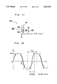
FIG. 12 shows vibrations of the vibrating mirror of the display apparatus K2. In FIG. 12, the abscissa represents time (t) and the ordinate represents angle (θ) of vibrations of the vibrating mirror. As shownin FIG. 12, the vibrating mirror makes a motion of sinusoidal wave expressed by the following equation.
θ=θm Sinωt
Supposing that character T denotes a period of vibrations of the vibrating mirror, scanning direction indicated by the arrow X in FIG. 5 represents scanning direction in the case where the LED array 61 has been turned on at a rise portion between the points A and B in the wave form. The rise portion occupies about 0.8×T/2. On the contrary, in the case where the LED array 61 has been turned on at a fall portion between the points Cand D in the wave form, the scanning direction is opposite to the directionof the arrow X.
In the case where the display apparatus is oriented upwardly, namely, when the gravity sensor 30 outputs the LOW U/D signal, the LED array 61 is turned on at the rise portion between the points A and B. Meanwhile, in the case where vertical orientation of the display apparatus K2 has been reversed, namely when the gravity sensor 30 outputs the HIGH U/D signal, the LED array 61 is turned on at the fall portion between the points C andD. This changeover can be performed quite easily by merely changing, by about T/2, timing of turning on of the LED array 61. However, if no measure is taken, not only the displayed picture is subjected to mirror inversion but sequence of turning on of the LEDs 1D, 2D,--100D of the odd rows and the LEDs 1E, 2E, --100E of the even rows in the zigzag LED array 61 is not corrected at all.
Thus, in order to prevent the displayed picture from being subjected to mirror inversion and correct sequence of turning on of the LEDs 1D, 2D,--100D of the odd rows and the LEDs 1E, 2E,--100E of the even rows, input of image signals to LED drivers 81 and 82 for driving the LED array 61 is changed from that of FIG. 5 as shown in FIG. 13. Namely, from a state shown in FIG. 5, a terminal E2 is disconnected from a terminal E1 and is connected to a terminal D1, while a terminal D2 is disconnected from the terminal D1 and is connected to the terminal E1 as shown in FIG. 13. In this case, image signals Dd and De are exactly identical with thoseof FIG. 5. By adopting the above described circuit configuration, the LEDs 100E, 99E,--2E and 1E of FIG. 13 are, respectively, driven by components 1d, 2d,--99d and 100d of the image signal Dd for driving the LED 1D, 2D,--99D and 100D of FIG. 5, respectively, while the LEDs 100D, 99D,--2D and 1D of FIG. 13 are, respectively, driven by components 1e, 2e,--99e and100e of the image signal De for driving the LEDs 1E, 2E,--99E and 100E of FIG. 5, respectively, whereby an image free from mirror inversion, in which sequence of turning on of the LEDs of the odd rows and the LEDs of the even rows has been corrected, can be obtained.
Thus, in the display apparatus K2, it becomes possible to easily change over vertical orientation of the picture by, in response to the U/D signalfrom the gravity sensor 30, merely not only changing timing of turning on of the LED array 61 but changing over input of the image signals to the LED drivers 81 and 82.
As will be seen from the description given so far, in the display apparatusaccording to the second embodiment of the present invention, the vertical orientation indicating means indicates whether the display apparatus is oriented upwardly or downwardly such that, in response to the signal from the vertical orientation indicating means indicative of whether the display apparatus is oriented upwardly or downwardly, the means for driving the LED array not only turns on the LED array at the rise region or the fall region of the sinusoidal wave-for driving the vibrating mirrorbut also sets sequence of turning on of the LED array in the forward direction or in the reverse direction. Consequently, in the second embodiment of the present invention, vertical orientation of the picture can be changed by the simple circuit based on whether the display apparatus is oriented upwardly or downwardly.
Although the present invention has been fully described by way of example with reference to the accompanying drawings, it is to be noted here that various changes and modifications will be apparent to those skilled in theart. Therefore, unless otherwise such changes and modifications depart fromthe scope of the present invention, they should be construed as being included therein.

Claims (6)

What is claimed is:
1. In a heads-up display apparatus in which light outputted from an LED display arranged in a column is reflected by a vibrating mirror driven in a sinusoidal wave such that a two-dimensional image is obtained, the improvement comprising:
first means for indicating whether said display is oriented upwardly or downwardly; and
LED driving means for driving said LED array, said driving means being responsive to a signal from said first means indicative of whether said display apparatus is oriented upwardly or downwardly such that:
if said first means indicates that the display apparatus is oriented upwardly, said LED driving means drives the LED array at a rise region of the sinusoidal wave while turning on said LED array in a forward direction; and
if said first means indicates that the display apparatus is oriented downwardly, said LED driving means drives the LED array at a fall region of the sinusoidal wave while turning on said LED array in a reverse direction.
2. A display apparatus as claimed in claim 1, wherein said first means is formed by a gravity sensor.
3. A display apparatus as claimed in claim 2, wherein said gravity sensor includes a hermetically sealed vessel, a pair of electrodes extending through one end of said vessel and electrically conductive liquid put in said vessel.
4. A display apparatus as claimed in claim 3, wherein said liquid is mercury.
5. In a heads-up display apparatus in which light outputted from an LED display arranged in a column is reflected by a vibrating mirror such that a two-dimensional image is obtained, the improvement comprising:
a first half mirror which reflects light from roughly half the visible spectrum, wherein the wavelengths of light reflected include the wavelength of light emitted by said LED array and transmits therethrough visible light having other wavelengths;
said first half mirror being so disposed as to not only transmit therethrough the visible light from outside but also reflect the light proceeding from said LED array via said vibrating mirror such that the two-dimensional image is viewed against a background of those elements of an outer scene containing spectral components transmitted by said first half mirror;
wherein the vibrating mirror is driven by a periodic signal and wherein the apparatus further comprises:
first means for indicating whether the display is oriented upwardly or downwardly; and
LED driving means for driving said LED array, said driving means being responsive to a signal from said first means indicative of whether said display apparatus is oriented upwardly or downwardly such that:
if said first means indicates that the display apparatus is oriented upwardly, said LED driving means drives the LED array during a first portion of the periodic signal while turning on said LED array in a forward direction; and
if said first means indicates that the display apparatus is oriented downwardly said LED driving means drives the LED array during a second portion of the periodic signal while turning on said LED array in a reverse direction.
6. A heads-up display apparatus, comprising:
a plurality of LED devices arranged in a column;
LED driving means for driving the LED devices;
a vibrating mirror placed so as to reflect light generated by the LED devices, said mirror driven by a periodic signal such that a two-dimensional image is obtained;
a first half mirror which reflects light from roughly half the visible spectrum, including the wavelength of light emitted by the LED devices, and transmits therethrough visible light having other wavelengths; and
first means for indicating whether the display apparatus is oriented upwardly or downwardly;
said driving means being responsive to a signal from said first means indicative of whether the display apparatus is oriented upwardly or downwardly such that:
if said first means indicates that the display apparatus is oriented upwardly, said LED driving means drives the column of LED devices during a first portion of the periodic signal while turning on said LED array in a forward direction; and
if said first means indicates that the display apparatus is oriented downwardly, said LED driving means drives the column of LED devices during a second portion of the periodic signal while turning on said LED array in a reverse direction; and
said first half mirror being disposed so as to not only transmit therethrough the visible light from outside but also reflect the light reflected from the vibrating mirror such that the two-dimensional image is viewed against a background of those elements of an outer scene containing spectral components transmitted by said first half mirror.
US07/966,116 1988-12-08 1992-10-23 Display apparatus Expired - Fee Related US5331333A (en)

Priority Applications (1)

Application Number Priority Date Filing Date Title
US07/966,116 US5331333A (en) 1988-12-08 1992-10-23 Display apparatus

Applications Claiming Priority (7)

Application Number Priority Date Filing Date Title
JP63-310447 1988-12-08
JP31044788A JPH068983B2 (en) 1988-12-08 1988-12-08 Display device
JP2355389A JP2659576B2 (en) 1989-01-31 1989-01-31 Display device
JP1-23553 1989-01-31
US43790289A 1989-11-16 1989-11-16
US77397591A 1991-10-08 1991-10-08
US07/966,116 US5331333A (en) 1988-12-08 1992-10-23 Display apparatus

Related Parent Applications (1)

Application Number Title Priority Date Filing Date
US77397591A Continuation 1988-12-08 1991-10-08

Publications (1)

Publication Number Publication Date
US5331333A true US5331333A (en) 1994-07-19

Family

ID=27457990

Family Applications (1)

Application Number Title Priority Date Filing Date
US07/966,116 Expired - Fee Related US5331333A (en) 1988-12-08 1992-10-23 Display apparatus

Country Status (1)

Country Link
US (1) US5331333A (en)

Cited By (52)

* Cited by examiner, † Cited by third party
Publication number Priority date Publication date Assignee Title
US5708449A (en) * 1993-10-07 1998-01-13 Virtual Vision, Inc. Binocular head mounted display system
WO1998009267A1 (en) * 1996-08-28 1998-03-05 Reflection Technology, Inc. Compact image generator with dual line emitter array
US5825338A (en) * 1991-05-09 1998-10-20 Atoma International Corp. Instrument display method and system for passenger vehicle
WO1999049655A1 (en) * 1998-03-25 1999-09-30 Mann W Stephen G Eye-tap for electronic newsgathering, documentary video, photojournalism, and personal safety
US5970418A (en) * 1995-09-21 1999-10-19 International Business Machines Corporation Personal communicator including a handset phone with an integrated virtual image display
US6219188B1 (en) * 1998-02-26 2001-04-17 Canon Kabushiki Kaisha Observation optical system
US6222508B1 (en) * 1995-08-25 2001-04-24 Massachusetts Institute Of Technology VLSI visual display
US6232937B1 (en) 1996-10-31 2001-05-15 Kopin Corporation Low power active display system
US20010017604A1 (en) * 1996-10-31 2001-08-30 Jeffrey Jacobsen Reflective microdisplay for portable communication system
US6307526B1 (en) 1998-02-02 2001-10-23 W. Steve G. Mann Wearable camera system with viewfinder means
US20020057915A1 (en) * 1998-10-29 2002-05-16 Mann W. Stephen G. Method and apparatus for enhancing personal safety with conspicuously concealed, incidentalist, concomitant, or deniable remote monitoring possibilities of a witnessential network, or the like
US6446862B1 (en) 1999-12-31 2002-09-10 W. Stephen G. Mann Point of purchase (PoP) terminal
US20020158823A1 (en) * 1997-10-31 2002-10-31 Matthew Zavracky Portable microdisplay system
US6545654B2 (en) * 1996-10-31 2003-04-08 Kopin Corporation Microdisplay for portable communication systems
US6552704B2 (en) 1997-10-31 2003-04-22 Kopin Corporation Color display with thin gap liquid crystal
US6559825B2 (en) 1996-10-31 2003-05-06 Kopin Corporation Display system for wireless pager
US6614408B1 (en) 1998-03-25 2003-09-02 W. Stephen G. Mann Eye-tap for electronic newsgathering, documentary video, photojournalism, and personal safety
US20040009456A1 (en) * 2002-07-11 2004-01-15 Mann Christina Ruth Method of assisting in the provision of medical care
US6847336B1 (en) 1996-10-02 2005-01-25 Jerome H. Lemelson Selectively controllable heads-up display system
US20060166468A1 (en) * 2003-05-06 2006-07-27 Canon Kabushiki Kaisha Semiconductor substrate, semiconductor device, light emitting diode and producing method therefor
US7321354B1 (en) 1996-10-31 2008-01-22 Kopin Corporation Microdisplay for portable communication systems
US7372447B1 (en) 1996-10-31 2008-05-13 Kopin Corporation Microdisplay for portable communication systems
US20080130272A1 (en) * 2005-05-17 2008-06-05 Michael Waters Hands-Free Lighting Devices
US8152330B2 (en) 2001-11-07 2012-04-10 Michael Waters Lighted reading glasses
US8235524B2 (en) 2001-11-07 2012-08-07 Michael Waters Illuminated eyewear
US8333485B2 (en) 2007-12-18 2012-12-18 Michael Waters Headwear with switch shielding portion
USD682343S1 (en) 2011-12-23 2013-05-14 Michael Waters Lighted glasses
US8444266B2 (en) 2009-09-30 2013-05-21 Michael Waters Illuminated eyewear
US8485682B2 (en) 2007-10-29 2013-07-16 Waters Industries, Inc. Illuminated eyeglass assembly
US8491145B2 (en) 2007-12-18 2013-07-23 Waters Industries, Inc. Illuminated headgear having switch devices and packaging therefor
US8491118B2 (en) 2001-11-07 2013-07-23 Michael Waters Lighted reading glasses
US8540364B2 (en) 2010-09-14 2013-09-24 Michael Waters Lighted glasses
US8545012B2 (en) 2005-05-17 2013-10-01 Michael Waters Illuminated eyewear
US8550651B2 (en) 2007-12-18 2013-10-08 Waters Industries, Inc. Lighted hat
US8757831B2 (en) 2007-12-18 2014-06-24 Michael Waters Headgear having an electrical device and power source mounted thereto
US8979295B2 (en) 2005-05-17 2015-03-17 Michael Waters Rechargeable lighted glasses
US9101174B2 (en) 2011-11-04 2015-08-11 Michael Waters Hat with automated shut-off feature for electrical devices
USD770143S1 (en) 2014-05-23 2016-11-01 Michael Waters Beanie with means for illumination
US9526287B2 (en) 2011-12-23 2016-12-27 Michael Waters Lighted hat
US9526292B2 (en) 2005-05-17 2016-12-27 Michael Waters Power modules and headgear
US9568173B2 (en) 2011-12-23 2017-02-14 Michael Waters Lighted hat
US9609902B2 (en) 2011-12-23 2017-04-04 Michael Waters Headgear having a camera device
US9717633B2 (en) 2013-03-15 2017-08-01 Michael Waters Lighted headgear
US9872530B2 (en) 2010-04-30 2018-01-23 Michael Waters Lighted headgear and accessories therefor
USD824557S1 (en) 2014-12-02 2018-07-31 Michael Waters Flashlight
US10069318B2 (en) 2014-12-02 2018-09-04 Michael Waters LED flashlight with longitudinal cooling fins
US10159294B2 (en) 2012-12-19 2018-12-25 Michael Waters Lighted solar hat
US10231676B2 (en) 1999-01-25 2019-03-19 Masimo Corporation Dual-mode patient monitor
US10359984B2 (en) * 2015-11-03 2019-07-23 Boe Technology Group Co., Ltd. Image display device and image display method
US20200226977A1 (en) * 2019-01-11 2020-07-16 Facebook Technologies, Llc Control scheme for a scanning display
US10791783B1 (en) 2019-05-16 2020-10-06 Waters Industries, Inc. Lighted headgear and accessories therefor
US11151916B2 (en) 2017-11-23 2021-10-19 Facebook Technologies, Llc Data shifting circuit for a current mode display

Citations (11)

* Cited by examiner, † Cited by third party
Publication number Priority date Publication date Assignee Title
US3170979A (en) * 1962-04-30 1965-02-23 Alan W Baldwin Optical image interposing display device
US4129982A (en) * 1977-03-08 1978-12-19 Cruz Virgil De Mercury switch arrangement for digital watch
US4368950A (en) * 1979-12-01 1983-01-18 Dainippon Screen Mfg., Co., Ltd. Image observation device having glass piled half mirror
US4447128A (en) * 1982-12-03 1984-05-08 Hughes Aircraft Company Diffraction head up display solar radiation filter
US4527155A (en) * 1981-03-04 1985-07-02 Nissan Motor Company, Limited System for maintaining an orientation of characters displayed with a rotatable image
US4542377A (en) * 1982-12-27 1985-09-17 International Business Machines Corporation Rotatable display work station
US4564291A (en) * 1979-12-19 1986-01-14 Tokyo Kogaku Kikai Kabushiki Kaisha Projection type lensmeter
US4736442A (en) * 1985-05-23 1988-04-05 Kornfeld Cary D System and method for orthogonal image transformation
US4823080A (en) * 1987-06-26 1989-04-18 Lin Dong Chang Touchless (photo type) and contact digital dual purpose tachometer
US4831368A (en) * 1986-06-18 1989-05-16 Hitachi, Ltd. Display apparatus with rotatable display screen
US4876488A (en) * 1987-09-30 1989-10-24 The Boeing Company Raster rotation circuit

Patent Citations (11)

* Cited by examiner, † Cited by third party
Publication number Priority date Publication date Assignee Title
US3170979A (en) * 1962-04-30 1965-02-23 Alan W Baldwin Optical image interposing display device
US4129982A (en) * 1977-03-08 1978-12-19 Cruz Virgil De Mercury switch arrangement for digital watch
US4368950A (en) * 1979-12-01 1983-01-18 Dainippon Screen Mfg., Co., Ltd. Image observation device having glass piled half mirror
US4564291A (en) * 1979-12-19 1986-01-14 Tokyo Kogaku Kikai Kabushiki Kaisha Projection type lensmeter
US4527155A (en) * 1981-03-04 1985-07-02 Nissan Motor Company, Limited System for maintaining an orientation of characters displayed with a rotatable image
US4447128A (en) * 1982-12-03 1984-05-08 Hughes Aircraft Company Diffraction head up display solar radiation filter
US4542377A (en) * 1982-12-27 1985-09-17 International Business Machines Corporation Rotatable display work station
US4736442A (en) * 1985-05-23 1988-04-05 Kornfeld Cary D System and method for orthogonal image transformation
US4831368A (en) * 1986-06-18 1989-05-16 Hitachi, Ltd. Display apparatus with rotatable display screen
US4823080A (en) * 1987-06-26 1989-04-18 Lin Dong Chang Touchless (photo type) and contact digital dual purpose tachometer
US4876488A (en) * 1987-09-30 1989-10-24 The Boeing Company Raster rotation circuit

Cited By (72)

* Cited by examiner, † Cited by third party
Publication number Priority date Publication date Assignee Title
US5825338A (en) * 1991-05-09 1998-10-20 Atoma International Corp. Instrument display method and system for passenger vehicle
US5708449A (en) * 1993-10-07 1998-01-13 Virtual Vision, Inc. Binocular head mounted display system
US6222508B1 (en) * 1995-08-25 2001-04-24 Massachusetts Institute Of Technology VLSI visual display
US5970418A (en) * 1995-09-21 1999-10-19 International Business Machines Corporation Personal communicator including a handset phone with an integrated virtual image display
WO1998009267A1 (en) * 1996-08-28 1998-03-05 Reflection Technology, Inc. Compact image generator with dual line emitter array
US6847336B1 (en) 1996-10-02 2005-01-25 Jerome H. Lemelson Selectively controllable heads-up display system
US20050206583A1 (en) * 1996-10-02 2005-09-22 Lemelson Jerome H Selectively controllable heads-up display system
US7372447B1 (en) 1996-10-31 2008-05-13 Kopin Corporation Microdisplay for portable communication systems
US6232937B1 (en) 1996-10-31 2001-05-15 Kopin Corporation Low power active display system
US20010017604A1 (en) * 1996-10-31 2001-08-30 Jeffrey Jacobsen Reflective microdisplay for portable communication system
US7321354B1 (en) 1996-10-31 2008-01-22 Kopin Corporation Microdisplay for portable communication systems
US6677936B2 (en) 1996-10-31 2004-01-13 Kopin Corporation Color display system for a camera
US6545654B2 (en) * 1996-10-31 2003-04-08 Kopin Corporation Microdisplay for portable communication systems
US6559825B2 (en) 1996-10-31 2003-05-06 Kopin Corporation Display system for wireless pager
US7242383B2 (en) 1997-10-31 2007-07-10 Kopin Corporation Portable microdisplay system
US20020158823A1 (en) * 1997-10-31 2002-10-31 Matthew Zavracky Portable microdisplay system
US6552704B2 (en) 1997-10-31 2003-04-22 Kopin Corporation Color display with thin gap liquid crystal
US6307526B1 (en) 1998-02-02 2001-10-23 W. Steve G. Mann Wearable camera system with viewfinder means
US6219188B1 (en) * 1998-02-26 2001-04-17 Canon Kabushiki Kaisha Observation optical system
WO1999049655A1 (en) * 1998-03-25 1999-09-30 Mann W Stephen G Eye-tap for electronic newsgathering, documentary video, photojournalism, and personal safety
US6614408B1 (en) 1998-03-25 2003-09-02 W. Stephen G. Mann Eye-tap for electronic newsgathering, documentary video, photojournalism, and personal safety
US20020085843A1 (en) * 1998-10-29 2002-07-04 Mann W. Stephen G. Wearable camera system with viewfinder means
US20020057915A1 (en) * 1998-10-29 2002-05-16 Mann W. Stephen G. Method and apparatus for enhancing personal safety with conspicuously concealed, incidentalist, concomitant, or deniable remote monitoring possibilities of a witnessential network, or the like
US10231676B2 (en) 1999-01-25 2019-03-19 Masimo Corporation Dual-mode patient monitor
US6446862B1 (en) 1999-12-31 2002-09-10 W. Stephen G. Mann Point of purchase (PoP) terminal
US8152330B2 (en) 2001-11-07 2012-04-10 Michael Waters Lighted reading glasses
US8235524B2 (en) 2001-11-07 2012-08-07 Michael Waters Illuminated eyewear
US8491118B2 (en) 2001-11-07 2013-07-23 Michael Waters Lighted reading glasses
US8899744B2 (en) 2001-11-07 2014-12-02 Michael Waters Lighted reading glasses
US20040009456A1 (en) * 2002-07-11 2004-01-15 Mann Christina Ruth Method of assisting in the provision of medical care
US20060166468A1 (en) * 2003-05-06 2006-07-27 Canon Kabushiki Kaisha Semiconductor substrate, semiconductor device, light emitting diode and producing method therefor
US7622363B2 (en) * 2003-05-06 2009-11-24 Canon Kabushiki Kaisha Semiconductor substrate, semiconductor device, light emitting diode and producing method therefor
US8388164B2 (en) 2005-05-17 2013-03-05 Michael Waters Hands-Free lighting devices
US9526292B2 (en) 2005-05-17 2016-12-27 Michael Waters Power modules and headgear
US9513495B2 (en) 2005-05-17 2016-12-06 Michael Waters Illuminated eyewear
US20080130272A1 (en) * 2005-05-17 2008-06-05 Michael Waters Hands-Free Lighting Devices
US8979295B2 (en) 2005-05-17 2015-03-17 Michael Waters Rechargeable lighted glasses
US8545012B2 (en) 2005-05-17 2013-10-01 Michael Waters Illuminated eyewear
US8485682B2 (en) 2007-10-29 2013-07-16 Waters Industries, Inc. Illuminated eyeglass assembly
US8491145B2 (en) 2007-12-18 2013-07-23 Waters Industries, Inc. Illuminated headgear having switch devices and packaging therefor
US8757831B2 (en) 2007-12-18 2014-06-24 Michael Waters Headgear having an electrical device and power source mounted thereto
US8550651B2 (en) 2007-12-18 2013-10-08 Waters Industries, Inc. Lighted hat
US8333485B2 (en) 2007-12-18 2012-12-18 Michael Waters Headwear with switch shielding portion
US9185278B2 (en) 2007-12-18 2015-11-10 Michael Waters Hands free lighting devices
US9585431B2 (en) 2007-12-18 2017-03-07 Waters Industries, Inc. Lighted hat
US8444266B2 (en) 2009-09-30 2013-05-21 Michael Waters Illuminated eyewear
US8567945B2 (en) 2009-09-30 2013-10-29 Michael Waters Illuminated eyewear
US11478035B2 (en) 2010-04-30 2022-10-25 Michael Waters Lighted headgear and accessories therefor
US9872530B2 (en) 2010-04-30 2018-01-23 Michael Waters Lighted headgear and accessories therefor
US10716350B2 (en) 2010-04-30 2020-07-21 Michael Waters Lighted headgear and accessories therefor
US10117476B2 (en) 2010-04-30 2018-11-06 Michael Waters Lighted headgear and accessories therefor
US8540364B2 (en) 2010-09-14 2013-09-24 Michael Waters Lighted glasses
US9101174B2 (en) 2011-11-04 2015-08-11 Michael Waters Hat with automated shut-off feature for electrical devices
US9526287B2 (en) 2011-12-23 2016-12-27 Michael Waters Lighted hat
USD682343S1 (en) 2011-12-23 2013-05-14 Michael Waters Lighted glasses
US9568173B2 (en) 2011-12-23 2017-02-14 Michael Waters Lighted hat
US9609902B2 (en) 2011-12-23 2017-04-04 Michael Waters Headgear having a camera device
US10159294B2 (en) 2012-12-19 2018-12-25 Michael Waters Lighted solar hat
US9717633B2 (en) 2013-03-15 2017-08-01 Michael Waters Lighted headgear
USD770143S1 (en) 2014-05-23 2016-11-01 Michael Waters Beanie with means for illumination
US10069318B2 (en) 2014-12-02 2018-09-04 Michael Waters LED flashlight with longitudinal cooling fins
US10847985B2 (en) 2014-12-02 2020-11-24 Michael Waters Flashlight with longitudinal cooling fins
USD824557S1 (en) 2014-12-02 2018-07-31 Michael Waters Flashlight
US10359984B2 (en) * 2015-11-03 2019-07-23 Boe Technology Group Co., Ltd. Image display device and image display method
US11151916B2 (en) 2017-11-23 2021-10-19 Facebook Technologies, Llc Data shifting circuit for a current mode display
US20200226977A1 (en) * 2019-01-11 2020-07-16 Facebook Technologies, Llc Control scheme for a scanning display
US10971061B2 (en) * 2019-01-11 2021-04-06 Facebook Technologies, Llc Control scheme for a scanning display
US11430384B2 (en) 2019-01-11 2022-08-30 Meta Platforms Technologies, Llc Control scheme for a scanning display
US20220383810A1 (en) * 2019-01-11 2022-12-01 Meta Platforms Technologies, Llc Control scheme for a scanning display
US11798471B2 (en) * 2019-01-11 2023-10-24 Meta Platforms Technologies, Llc Control scheme for a scanning display
US10791783B1 (en) 2019-05-16 2020-10-06 Waters Industries, Inc. Lighted headgear and accessories therefor
US11206888B2 (en) 2019-05-16 2021-12-28 Waters Industries, Inc. Lighted headgear and accessories therefor

Similar Documents

Publication Publication Date Title
US5331333A (en) Display apparatus
US4299447A (en) Liquid crystal fiber optics large screen display panel
JP4181660B2 (en) Video display apparatus and method
US5327263A (en) Image processing apparatus employing a spatial light modulator
EP0301801B1 (en) Miniature video display system
US5404236A (en) Display device with crossing electrodes with specific ratio for gray scale
KR950033935A (en) Optical deflection device, optical scanning device, information reading device and stereoscopic display device
KR920018507A (en) Image projection method obtained using liquid crystal panel and display device for realizing this
US6700557B1 (en) Electrode border for spatial light modulating displays
US4403834A (en) Acoustic-wave device
JP3856141B2 (en) Lens barrel and imaging device
JPH0865690A (en) Color still picture photographing device
US5859624A (en) Binocular display goggles with a one dimensional light source array scanned to form image of high dot density data
US5189545A (en) Optical deflector and display unit using the same
JP2005250026A (en) Liquid crystal dimmer element, lens barrel, and image pickup device
JP2659576B2 (en) Display device
GB2232268A (en) "Optical deflector and display unit using the same"
US5630001A (en) Image generator for use in image manifestation apparatus
JPH05127113A (en) Picture display device and stereoscopic image display device
JPH0361927A (en) Liquid crystal display device
JP4407176B2 (en) Display device
JPH0357455B2 (en)
KR20230111699A (en) Stereoscopic image display device
EP0898729B1 (en) Optical switching element and a camera comprising such an optical element
JPH04307590A (en) Binocular image display device

Legal Events

Date Code Title Description
FEPP Fee payment procedure

Free format text: PAYOR NUMBER ASSIGNED (ORIGINAL EVENT CODE: ASPN); ENTITY STATUS OF PATENT OWNER: LARGE ENTITY

FEPP Fee payment procedure

Free format text: PAYOR NUMBER ASSIGNED (ORIGINAL EVENT CODE: ASPN); ENTITY STATUS OF PATENT OWNER: LARGE ENTITY

Free format text: PAYER NUMBER DE-ASSIGNED (ORIGINAL EVENT CODE: RMPN); ENTITY STATUS OF PATENT OWNER: LARGE ENTITY

FEPP Fee payment procedure

Free format text: PAYER NUMBER DE-ASSIGNED (ORIGINAL EVENT CODE: RMPN); ENTITY STATUS OF PATENT OWNER: LARGE ENTITY

Free format text: PAYOR NUMBER ASSIGNED (ORIGINAL EVENT CODE: ASPN); ENTITY STATUS OF PATENT OWNER: LARGE ENTITY

FPAY Fee payment

Year of fee payment: 4

REMI Maintenance fee reminder mailed
LAPS Lapse for failure to pay maintenance fees
STCH Information on status: patent discontinuation

Free format text: PATENT EXPIRED DUE TO NONPAYMENT OF MAINTENANCE FEES UNDER 37 CFR 1.362

FP Lapsed due to failure to pay maintenance fee

Effective date: 20020719