US5330451A - Multi purpose perfusion cannula - Google Patents
Multi purpose perfusion cannula Download PDFInfo
- Publication number
- US5330451A US5330451A US07/992,116 US99211692A US5330451A US 5330451 A US5330451 A US 5330451A US 99211692 A US99211692 A US 99211692A US 5330451 A US5330451 A US 5330451A
- Authority
- US
- United States
- Prior art keywords
- cannula
- aortic
- intra
- balloon
- aorta
- Prior art date
- Legal status (The legal status is an assumption and is not a legal conclusion. Google has not performed a legal analysis and makes no representation as to the accuracy of the status listed.)
- Expired - Lifetime
Links
Images


Classifications
-
- A—HUMAN NECESSITIES
- A61—MEDICAL OR VETERINARY SCIENCE; HYGIENE
- A61M—DEVICES FOR INTRODUCING MEDIA INTO, OR ONTO, THE BODY; DEVICES FOR TRANSDUCING BODY MEDIA OR FOR TAKING MEDIA FROM THE BODY; DEVICES FOR PRODUCING OR ENDING SLEEP OR STUPOR
- A61M25/00—Catheters; Hollow probes
- A61M25/10—Balloon catheters
- A61M25/1011—Multiple balloon catheters
-
- A—HUMAN NECESSITIES
- A61—MEDICAL OR VETERINARY SCIENCE; HYGIENE
- A61M—DEVICES FOR INTRODUCING MEDIA INTO, OR ONTO, THE BODY; DEVICES FOR TRANSDUCING BODY MEDIA OR FOR TAKING MEDIA FROM THE BODY; DEVICES FOR PRODUCING OR ENDING SLEEP OR STUPOR
- A61M1/00—Suction or pumping devices for medical purposes; Devices for carrying-off, for treatment of, or for carrying-over, body-liquids; Drainage systems
- A61M1/36—Other treatment of blood in a by-pass of the natural circulatory system, e.g. temperature adaptation, irradiation ; Extra-corporeal blood circuits
- A61M1/3621—Extra-corporeal blood circuits
- A61M1/3653—Interfaces between patient blood circulation and extra-corporal blood circuit
- A61M1/3659—Cannulae pertaining to extracorporeal circulation
-
- A—HUMAN NECESSITIES
- A61—MEDICAL OR VETERINARY SCIENCE; HYGIENE
- A61M—DEVICES FOR INTRODUCING MEDIA INTO, OR ONTO, THE BODY; DEVICES FOR TRANSDUCING BODY MEDIA OR FOR TAKING MEDIA FROM THE BODY; DEVICES FOR PRODUCING OR ENDING SLEEP OR STUPOR
- A61M60/00—Blood pumps; Devices for mechanical circulatory actuation; Balloon pumps for circulatory assistance
- A61M60/10—Location thereof with respect to the patient's body
- A61M60/122—Implantable pumps or pumping devices, i.e. the blood being pumped inside the patient's body
- A61M60/126—Implantable pumps or pumping devices, i.e. the blood being pumped inside the patient's body implantable via, into, inside, in line, branching on, or around a blood vessel
- A61M60/135—Implantable pumps or pumping devices, i.e. the blood being pumped inside the patient's body implantable via, into, inside, in line, branching on, or around a blood vessel inside a blood vessel, e.g. using grafting
- A61M60/139—Implantable pumps or pumping devices, i.e. the blood being pumped inside the patient's body implantable via, into, inside, in line, branching on, or around a blood vessel inside a blood vessel, e.g. using grafting inside the aorta, e.g. intra-aortic balloon pumps
-
- A—HUMAN NECESSITIES
- A61—MEDICAL OR VETERINARY SCIENCE; HYGIENE
- A61M—DEVICES FOR INTRODUCING MEDIA INTO, OR ONTO, THE BODY; DEVICES FOR TRANSDUCING BODY MEDIA OR FOR TAKING MEDIA FROM THE BODY; DEVICES FOR PRODUCING OR ENDING SLEEP OR STUPOR
- A61M60/00—Blood pumps; Devices for mechanical circulatory actuation; Balloon pumps for circulatory assistance
- A61M60/10—Location thereof with respect to the patient's body
- A61M60/122—Implantable pumps or pumping devices, i.e. the blood being pumped inside the patient's body
- A61M60/126—Implantable pumps or pumping devices, i.e. the blood being pumped inside the patient's body implantable via, into, inside, in line, branching on, or around a blood vessel
- A61M60/152—Implantable pumps or pumping devices, i.e. the blood being pumped inside the patient's body implantable via, into, inside, in line, branching on, or around a blood vessel branching on and drawing blood from a blood vessel
-
- A—HUMAN NECESSITIES
- A61—MEDICAL OR VETERINARY SCIENCE; HYGIENE
- A61M—DEVICES FOR INTRODUCING MEDIA INTO, OR ONTO, THE BODY; DEVICES FOR TRANSDUCING BODY MEDIA OR FOR TAKING MEDIA FROM THE BODY; DEVICES FOR PRODUCING OR ENDING SLEEP OR STUPOR
- A61M60/00—Blood pumps; Devices for mechanical circulatory actuation; Balloon pumps for circulatory assistance
- A61M60/20—Type thereof
- A61M60/295—Balloon pumps for circulatory assistance
-
- A—HUMAN NECESSITIES
- A61—MEDICAL OR VETERINARY SCIENCE; HYGIENE
- A61M—DEVICES FOR INTRODUCING MEDIA INTO, OR ONTO, THE BODY; DEVICES FOR TRANSDUCING BODY MEDIA OR FOR TAKING MEDIA FROM THE BODY; DEVICES FOR PRODUCING OR ENDING SLEEP OR STUPOR
- A61M60/00—Blood pumps; Devices for mechanical circulatory actuation; Balloon pumps for circulatory assistance
- A61M60/30—Medical purposes thereof other than the enhancement of the cardiac output
- A61M60/31—Medical purposes thereof other than the enhancement of the cardiac output for enhancement of in vivo organ perfusion, e.g. retroperfusion
-
- A—HUMAN NECESSITIES
- A61—MEDICAL OR VETERINARY SCIENCE; HYGIENE
- A61M—DEVICES FOR INTRODUCING MEDIA INTO, OR ONTO, THE BODY; DEVICES FOR TRANSDUCING BODY MEDIA OR FOR TAKING MEDIA FROM THE BODY; DEVICES FOR PRODUCING OR ENDING SLEEP OR STUPOR
- A61M60/00—Blood pumps; Devices for mechanical circulatory actuation; Balloon pumps for circulatory assistance
- A61M60/40—Details relating to driving
- A61M60/465—Details relating to driving for devices for mechanical circulatory actuation
- A61M60/489—Details relating to driving for devices for mechanical circulatory actuation the force acting on the actuation means being magnetic
- A61M60/495—Electromagnetic force
-
- A—HUMAN NECESSITIES
- A61—MEDICAL OR VETERINARY SCIENCE; HYGIENE
- A61M—DEVICES FOR INTRODUCING MEDIA INTO, OR ONTO, THE BODY; DEVICES FOR TRANSDUCING BODY MEDIA OR FOR TAKING MEDIA FROM THE BODY; DEVICES FOR PRODUCING OR ENDING SLEEP OR STUPOR
- A61M60/00—Blood pumps; Devices for mechanical circulatory actuation; Balloon pumps for circulatory assistance
- A61M60/50—Details relating to control
- A61M60/508—Electronic control means, e.g. for feedback regulation
- A61M60/515—Regulation using real-time patient data
- A61M60/531—Regulation using real-time patient data using blood pressure data, e.g. from blood pressure sensors
-
- A—HUMAN NECESSITIES
- A61—MEDICAL OR VETERINARY SCIENCE; HYGIENE
- A61M—DEVICES FOR INTRODUCING MEDIA INTO, OR ONTO, THE BODY; DEVICES FOR TRANSDUCING BODY MEDIA OR FOR TAKING MEDIA FROM THE BODY; DEVICES FOR PRODUCING OR ENDING SLEEP OR STUPOR
- A61M60/00—Blood pumps; Devices for mechanical circulatory actuation; Balloon pumps for circulatory assistance
- A61M60/50—Details relating to control
- A61M60/508—Electronic control means, e.g. for feedback regulation
- A61M60/562—Electronic control means, e.g. for feedback regulation for making blood flow pulsatile in blood pumps that do not intrinsically create pulsatile flow
-
- A—HUMAN NECESSITIES
- A61—MEDICAL OR VETERINARY SCIENCE; HYGIENE
- A61M—DEVICES FOR INTRODUCING MEDIA INTO, OR ONTO, THE BODY; DEVICES FOR TRANSDUCING BODY MEDIA OR FOR TAKING MEDIA FROM THE BODY; DEVICES FOR PRODUCING OR ENDING SLEEP OR STUPOR
- A61M60/00—Blood pumps; Devices for mechanical circulatory actuation; Balloon pumps for circulatory assistance
- A61M60/80—Constructional details other than related to driving
- A61M60/855—Constructional details other than related to driving of implantable pumps or pumping devices
- A61M60/861—Connections or anchorings for connecting or anchoring pumps or pumping devices to parts of the patient's body
-
- A—HUMAN NECESSITIES
- A61—MEDICAL OR VETERINARY SCIENCE; HYGIENE
- A61M—DEVICES FOR INTRODUCING MEDIA INTO, OR ONTO, THE BODY; DEVICES FOR TRANSDUCING BODY MEDIA OR FOR TAKING MEDIA FROM THE BODY; DEVICES FOR PRODUCING OR ENDING SLEEP OR STUPOR
- A61M60/00—Blood pumps; Devices for mechanical circulatory actuation; Balloon pumps for circulatory assistance
- A61M60/80—Constructional details other than related to driving
- A61M60/855—Constructional details other than related to driving of implantable pumps or pumping devices
- A61M60/865—Devices for guiding or inserting pumps or pumping devices into the patient's body
-
- A—HUMAN NECESSITIES
- A61—MEDICAL OR VETERINARY SCIENCE; HYGIENE
- A61M—DEVICES FOR INTRODUCING MEDIA INTO, OR ONTO, THE BODY; DEVICES FOR TRANSDUCING BODY MEDIA OR FOR TAKING MEDIA FROM THE BODY; DEVICES FOR PRODUCING OR ENDING SLEEP OR STUPOR
- A61M2210/00—Anatomical parts of the body
- A61M2210/12—Blood circulatory system
- A61M2210/127—Aorta
-
- A—HUMAN NECESSITIES
- A61—MEDICAL OR VETERINARY SCIENCE; HYGIENE
- A61M—DEVICES FOR INTRODUCING MEDIA INTO, OR ONTO, THE BODY; DEVICES FOR TRANSDUCING BODY MEDIA OR FOR TAKING MEDIA FROM THE BODY; DEVICES FOR PRODUCING OR ENDING SLEEP OR STUPOR
- A61M2230/00—Measuring parameters of the user
- A61M2230/30—Blood pressure
-
- A—HUMAN NECESSITIES
- A61—MEDICAL OR VETERINARY SCIENCE; HYGIENE
- A61M—DEVICES FOR INTRODUCING MEDIA INTO, OR ONTO, THE BODY; DEVICES FOR TRANSDUCING BODY MEDIA OR FOR TAKING MEDIA FROM THE BODY; DEVICES FOR PRODUCING OR ENDING SLEEP OR STUPOR
- A61M60/00—Blood pumps; Devices for mechanical circulatory actuation; Balloon pumps for circulatory assistance
- A61M60/80—Constructional details other than related to driving
- A61M60/802—Constructional details other than related to driving of non-positive displacement blood pumps
- A61M60/833—Occluders for preventing backflow
Definitions
- the present invention is directed to an improved perfusion cannula, more particularly one for use in the aorta during open heart surgery.
- IMA internal mammary artery
- a further problem resides in the age of the patients and the condition of their arteries. It is common to find diffuse atherosclerosis in such patients, as well as aortas which are seeded with calcified plaque. Thus, the risk of stroke is substantially increased because, if a small piece of calcium is dislodged, it can easily be carried to the brain as an embolism through, for example, the brachiocephalic artery. This can occur as a direct result of certain mechanisms; specifically, cross clamping of the ascending aorta to isolate and cool the heart for the surgery.
- Another cause is the jet of blood exiting from the aortic cannula which can, if it impinges on the walls of the aorta, dislodge plaque therefrom, especially in the region of the aortic arch. Moreover, this area generally has greater calcium deposits than any other part of the aorta.
- EAP extra-aortic pump
- Still another problem relates to the perioperative monitoring of the patient's blood pressure. This can be extremely difficult, and sometimes even impossible, the use of either the radial or femoral artery.
- the IABP can be used for such high risk patients as those suffering from (1) severe left main coronary artery disease, (2) failed angioplasty, (3) failed arterectomy, (4) low ejection fraction, (5) intractable angina, (6) severe triple vessel coronary disease, (7) repeat coronary artery bypass grafting, (8) prevention of IMA spasm, (9) post-operative crisis, (10) temporary post-operative low output syndrome, and (11) in any situation in which introduction of the balloon through the femoral arteries is inadvisable or impossible.
- the present invention provides a means whereby an extra-aortic pump can be quickly connected directly to the cannula for immediate operation.
- the extra-aortic pump can also be used to convert a cardiopulmonary bypass to a pulsatile bypass, thus minimizing the onset of complications which result from non-pulsatile bypasses.
- the pump can be used in severe post-operative heart failure and, if the patient is temporarily dependent on the pump, the device can be inserted directly through the ascending aorta after the cannula has been removed.
- the present invention also permits monitoring blood pressure deep inside the aorta. This can be done while the IABP or extra-aortic pump is operational, as well as while the patient is on the cardiopulmonary bypass.
- the cannula of the present invention is provided with an inflatable balloon which acts to occlude the aorta adjacent the heart. This isolates the latter and obviates the need for cross clamping. Cross clamping and dislodgment of debris by the cannula are the two main reasons for the formation of calcium embolisms, a major cause of stroke.
- the device eliminates the need to cool the patient to extreme low temperatures, nor is it necessary to perform the operation with complete circulatory arrest. The latter, in particular, carries a very high morbidity.
- the present invention provides a cannula which, while it will be described in connection with aortic perfusion, is capable of uses elsewhere as well.
- it comprises a perfusion cannula especially adapted for insertion into the aorta.
- a main channel which is fluidly connected at one end to an intra-aortic portion of the cannula and, at the other end, is fluidly connected to the aortic perfusion line of a cardiopulmonary bypass.
- a first side port which can be fluidly connected to an extra-aortic pump or to an intra-aortic balloon pump. The other end of the first port is in fluid connection with the intra-aortic portion of the cannula. This arrangement permits the insertion of the intra-aortic balloon pump through the first port, into the intra-aortic portion of the cannula, and beyond into the descending aorta.
- a blood pressure port is also provided which is fluidly connected to a blood pressure monitoring tube.
- the tube in turn, is located within the intra-aortic portion and extends therein to a pressure point which is upstream of the distal end of the portion.
- the other end of the tube is adapted for connection to a blood pressure measuring or monitoring device.
- the cannula is inserted in the aortic arch and, in the primary embodiment of the invention, extends a relatively short distance longitudinally of the aorta.
- the portion may terminate approximately opposite the brachiocephalic artery.
- the end of the first port remote from the portion may have a plug located therein. Within the plug is a one-way valve which prevents outward flow of blood, but permits insertion of the intra-aortic balloon.
- the balloon is controlled by a console which electronically monitors the heart beat and expands and contracts the balloon in synchronism therewith.
- the extra-aortic pump displaces a much greater volume than does the IABP, because it is close to the coronary arteries, it is necessary to remove the plug (along with the valve) before attaching the extra-aortic pump to the cannula.
- an inflatable occlusive balloon surrounds at least part of the intra-aortic portion of the cannula.
- the first port is also fluidly connected to the occlusive balloon and adapted for connection to an intra-aortic balloon pump, as well as to a control device therefor.
- the IABP console can operate the extra-aortic pump, as well.
- the occlusive balloon is provided as previously described.
- an inflatable non-occlusive balloon surrounds the intra-aortic portion at or adjacent the distal end thereof.
- the portion is longer than in the first two embodiments and the distal end is located in the descending aorta.
- the non-occlusive balloon serves two purposes. First, it acts as a guide to lead the intra-aortic portion around the curve of the aortic arch into the descending aorta. It minimizes the contact between the distal end of the portion and the anterior wall of the aorta. In this way, the likelihood of dislodgment of a calcium particle is reduced.
- the main channel and the intra-aortic portion constitute or contain a blood passage
- the presence of the non-occlusive balloon centers the exit of the blood passage so that the stream of perfused blood coming from the cardiopulmonary bypass is substantially parallel to the walls of the descending aorta.
- impingement of the stream on the walls is kept to a minimum. This, too, substantially reduces the risk of calcium particles being dislodged.
- a girdle around the aorta This is a strip of material which is wrapped around the aorta in order to reinforce it and prevent rupture of the artery wall. It is provided with strings attached to the ends whereby it can be tied in place. It is also provided with a hole through which the cannula of the present invention can be inserted. The girdle is tied to the aorta, and the surgeon stitches the girdle to the aorta immediately around the hole, prior to insertion of the cannula. It has been found advantageous to use a "purse string suture" which, after the cannula has been inserted, will pull the edges of the aortic opening closely around the cannula, thereby minimizing blood loss.
- the girdle should be made of either an inelastic material or one which is only slightly elastic. Since the material is to act as a reinforcement of the aorta, it should not be too elastic, as this would interfere with its primary function. After the surgery is complete, the girdle may be left in the patient as a permanent reinforcement.
- the material may be Dacron, Teflon, or any other suitable biological or prosthetic material. Xenograft pericardium has been found quite useful.
- a further advantage of the girdle is that it can comprise a fabric graft (preferably about 6 mm in length) sewed thereto to carry a blood pressure sensor below the sternum to the skin surface.
- the intra-aortic balloon can be removed and the wound closed.
- the projecting graft portion then provides a means whereby the blood pressure of the patient can be continuously monitored. When this is no longer required, the outer end is buried in the skin and sewn in place.
- a trocar which is flexible and moves axially within the cannula itself.
- the trocar is hollow and contains a guide wire by which the surgeon is able to manipulate it and minimize or avoid damage to the artery walls.
- the trocar terminates, at its inner end, in a head which comes to a point. After the surgeon has made the initial incision in the artery, the point of the trocar is inserted to dilate the opening. To facilitate the elimination of air, the head contains holes, preferably one at each of the upper and lower surfaces of the head and one at the point, to allow air and blood to pass through the head to the rear portion of the trocar. The air, along with some blood, is permitted to leak out of the cannula due to the imperfect fit between the guide wire and the plug at the outer end. When the trocar is almost completely withdrawn, the cannula is clamped to prevent any further loss. Thereafter, the trocar is completely removed and the cannula is connected to the perfusion line of a cardiopulmonary bypass. This eliminates or minimizes the risk of an air bubble getting to the brain of the patient. Moreover, it also minimizes blood loss.
- FIG. 1 is a schematic view, partly in section, of the first embodiment of the present device with the intra-aortic portion located in the aorta;
- FIG. 2 is a view similar to that of FIG. 1 showing the second embodiment of the invention with the occlusive balloon and an intra-aortic balloon positioned in the aorta;
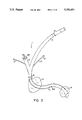
- FIG. 3 is a view similar to that of FIG. 1 of the third embodiment of the invention, without the aorta, but with both the occlusive balloon and the non-occlusive balloon in place;
- FIG. 4 is a view similar to that of FIG. 1 of the embodiment of FIG. 3 with an intra-aortic balloon in the descending aorta;
- FIG. 5 is a schematic sectional view of the non-occlusive balloon
- FIG. 6 is a schematic view of the girdle of the present invention after it has been stitched to the aorta but before it has been wrapped therearound;
- FIG. 7 is a view similar to that of FIG. 6 wherein the girdle has been partly wrapped around the aorta;
- FIG. 8 is a view similar to that FIG. 6 wherein the girdle has been wrapped entirely around the aorta and tied in place;
- FIG. 9 is a schematic view, partly in section, of the cannula of the present invention with a trocar within.
- cannula 1 comprises main channel 2, intra-aortic portion 11, first side port 3, and blood pressure port 5.
- Main channel 2 is connected to the aortic perfusion line of a cardiopulmonary bypass (not shown) and carries the perfused blood into intra-aortic portion 11.
- First port 3 is connected to extra-aortic pump 38which includes diaphragm 39. The pump alternately pumps blood in and withdraws it and is controlled by console 41.
- Blood pressure port 5 receives blood pressure tube 46 which extends within cannula 1 to opening 44 adjacent the distal end of intra-aortic portion 11. When opening 44 is located in this manner, the blood pressure reading is not influenced by the flow of blood exiting intra-aortic portion 11. The other end of tube 46 is connected to blood pressure monitor 40.
- locator ring 8 is placed on cannula 1 sothat the proper depth of insertion can easily be accomplished.
- the aorta comprises ascending aorta 16, aortic arch 17, and descending aorta 18 (notshown in FIG. 1).
- cannula 1 is inserted into ascending aorta 16or aortic arch 17, but upstream of brachiocephalic artery 31.
- Cannula 1 comprisesmain channel 2, intra-aortic portion 11, first side port 3, and blood pressure port 5, all substantially as described with respect to FIG. 1.
- occlusive balloon 13 which completely blocks ascending aorta 16. This enables heart 9 and aortic valve 10 to be isolated while the surgery is performed.
- Second side port 6 is provided tointroduce and withdraw fluid into and out of occlusive balloon 13. If the blend is air, it increases the risk to the patient, as an air bubble couldbe formed should balloon 13 rupture. Therefore, it is preferable that a liquid such as saline be used for this purpose.
- Fluid tube 4 carries the fluid which is used to inflate and deflate balloon 15.
- This form of the device can be used with intra-aortic balloon 15.
- This is part of a intra-aortic balloon pump wherein fluid is introduced into and withdrawn from balloon 15 as indicated by arrow 45.
- the action of the pump is controlled by console 41 (see FIG. 1).
- Balloon 15 is inserted past brachiocephalic artery 31, carotid artery 32, and subclavian artery 33 into descending aorta 18.
- FIG. 3 still another form of the device is shown, but without particular reference to the aorta in which it may be placed.
- Cannula 1 is similar to the embodiment shown in FIG. 2, but the intra-aortic balloon isnot present. Most of the elements correspond with the device of FIG. 2 and need not be further described here.
- intra-aortic portion 11 is substantially longer than its corresponding part in the embodiment shown in FIG. 2.
- non-occlusive balloon 14 is providedadjacent its distal end.
- Second side port 6 is connected to fluid tube 23 which feeds fluid to--and withdraws it from--balloon 14.
- First side port 3 is provided with plug 35 containing one-way valve 36.
- Valve 36 prevents blood from flowing out of port 3, but permits the insertion of an intra-aortic balloon pump therethrough, if needed.
- Port 3 can also receivean extra-aortic pump, but it is necessary to remove plug 35 before the insertion thereof. This is important because the volume of blood pumped bythe extra-aortic pump is much larger than that pumped by the intra-aortic balloon pump.
- FIG. 4 the foregoing embodiment is shown in the aorta along with intra-aortic balloon 15.
- Third side port 34 is connected to fluid tube 47 which carries fluid to and from balloon 14.
- a cross-section of balloon 14 is shown in FIG. 5.
- Balloon 14 is provided with lobes 37 and surrounds portion 11. Balloon 14 performs two functions. On insertion of cannula 1 into the aorta, it gently guides portion 11 around the aortic arch past arteries 31, 32, and 33. As a result, the pressure and stress on the anterior wall of the aorta are minimized and the risk of dislodgment of calcium plaque, which is frequently found at that point, is reduced.
- balloon 14 centers the distal end of portion 11 and blood passage 42.
- the stream thereof is substantially parallel to the walls of the descending aorta, it does not impinge to any degree upon those walls and, therefore, the chance of plaque being dislodged is substantially and materially reduced.
- Girdle 19 is provided to strengthen and reinforce the aorta.
- Hole 24 is provided in girdle 19 and sealing ring 30 is located on portion 11.
- Girdle24 is sutured to the aorta around the periphery of hole 24.
- Sleeve 43 slidably surrounds suture 7 so that the surgeon can pull on suture 7 whileholding sleeve 43 with forceps 12 to draw the purse string sutures (not shown) and cause the aorta to grip cannula 1 tightly.
- a good seal is provided so that blood does not leak out.
- Girdle 19 is shown in FIG. 6. It comprises wide section 25, left and right strings 21 and 22, respectively, slit 20, and hole 24. Purse string sutures 26 secure girdle 19 to the aorta. Calcium particles 29 are shown deposited on the interior wall of the aorta.
- girdle 19 is wrapped around the aorta in the direction of arrows 27.
- Left string 21 is drawn through slot 20 as shown in FIG. 7, andright strap 22 is passed underneath the aorta.
- the final stage is shown in FIG. 8 wherein girdle 19 is completely wrapped around the aorta, sutured thereto and tied at 28. Excess strings 21 and 22 are, of course, cut off.
- the girdle In a preferred form of the girdle, it is double walled and has a silicone patch between the layers. This permits the insertion of a blood pressure sensing tube which may remain in the aorta even after the operation is complete. It enables accurate monitoring of the blood pressure during post-operative treatment. When the sensor is to be removed, it is simply pulled out; the opening which it leaves in the wall of the aorta is sealedby the silicone, thereby virtually eliminating any internal bleeding resulting therefrom.
- hollow trocar 48 having head 49and point 51. Holes 50 are in head 49 to allow the passage of blood therethrough and guide wire 52 is located within trocar 48. Air and blood pass through holes 50 into the rear portion of trocar 48 and leak out between wire 52 and plug 35. After all the air has been discharged, cannula 1 is clamped when trocar 48 is almost withdrawn. Plug 35 is removed and cannula 1 is connected to the perfusion line of a cardiopulmonary bypass. Thereafter, the clamp is released so that the perfused blood can circulate within the patient.
Abstract
Description
Claims (10)
Priority Applications (6)
| Application Number | Priority Date | Filing Date | Title |
|---|---|---|---|
| US07/992,116 US5330451A (en) | 1992-12-17 | 1992-12-17 | Multi purpose perfusion cannula |
| CA002110842A CA2110842A1 (en) | 1992-12-17 | 1993-12-07 | Multi purpose perfusion cannula |
| EP93119918A EP0604803B1 (en) | 1992-12-17 | 1993-12-10 | Multi purpose perfusion cannula |
| DE69331626T DE69331626T2 (en) | 1992-12-17 | 1993-12-10 | Multi-purpose infusion cannula |
| JP5343985A JPH06277278A (en) | 1992-12-17 | 1993-12-17 | Perfusion cannula and girdle and trocar used for it |
| US08/200,211 US5599329A (en) | 1992-12-17 | 1994-02-23 | Multi purpose perfusion cannula |
Applications Claiming Priority (1)
| Application Number | Priority Date | Filing Date | Title |
|---|---|---|---|
| US07/992,116 US5330451A (en) | 1992-12-17 | 1992-12-17 | Multi purpose perfusion cannula |
Related Child Applications (1)
| Application Number | Title | Priority Date | Filing Date |
|---|---|---|---|
| US08/200,211 Division US5599329A (en) | 1992-12-17 | 1994-02-23 | Multi purpose perfusion cannula |
Publications (1)
| Publication Number | Publication Date |
|---|---|
| US5330451A true US5330451A (en) | 1994-07-19 |
Family
ID=25537919
Family Applications (2)
| Application Number | Title | Priority Date | Filing Date |
|---|---|---|---|
| US07/992,116 Expired - Lifetime US5330451A (en) | 1992-12-17 | 1992-12-17 | Multi purpose perfusion cannula |
| US08/200,211 Expired - Fee Related US5599329A (en) | 1992-12-17 | 1994-02-23 | Multi purpose perfusion cannula |
Family Applications After (1)
| Application Number | Title | Priority Date | Filing Date |
|---|---|---|---|
| US08/200,211 Expired - Fee Related US5599329A (en) | 1992-12-17 | 1994-02-23 | Multi purpose perfusion cannula |
Country Status (5)
| Country | Link |
|---|---|
| US (2) | US5330451A (en) |
| EP (1) | EP0604803B1 (en) |
| JP (1) | JPH06277278A (en) |
| CA (1) | CA2110842A1 (en) |
| DE (1) | DE69331626T2 (en) |
Cited By (51)
| Publication number | Priority date | Publication date | Assignee | Title |
|---|---|---|---|---|
| US5669881A (en) * | 1995-01-10 | 1997-09-23 | Baxter International Inc. | Vascular introducer system incorporating inflatable occlusion balloon |
| US5702368A (en) * | 1991-07-16 | 1997-12-30 | Heartport, Inc. | System for cardiac procedures |
| US5701905A (en) * | 1995-11-13 | 1997-12-30 | Localmed, Inc. | Guide catheter with sensing element |
| US5755687A (en) | 1997-04-01 | 1998-05-26 | Heartport, Inc. | Methods and devices for occluding a patient's ascending aorta |
| US5765568A (en) | 1994-05-27 | 1998-06-16 | Heartport, Inc. | Catheter system and method for venting the left ventricle |
| US5769816A (en) * | 1995-11-07 | 1998-06-23 | Embol-X, Inc. | Cannula with associated filter |
| US5769812A (en) | 1991-07-16 | 1998-06-23 | Heartport, Inc. | System for cardiac procedures |
| US5846260A (en) * | 1997-05-08 | 1998-12-08 | Embol-X, Inc. | Cannula with a modular filter for filtering embolic material |
| US5868703A (en) * | 1996-04-10 | 1999-02-09 | Endoscopic Technologies, Inc. | Multichannel catheter |
| WO1999030766A1 (en) | 1997-12-18 | 1999-06-24 | Embol-X, Inc. | Cardioplegia occluder |
| US5979455A (en) * | 1991-07-03 | 1999-11-09 | Maginot Vascular Systems | Method for directing blood flow in the body of a patient with a graft and stent assembly |
| US5980503A (en) * | 1996-04-08 | 1999-11-09 | Guidant Corporation | Endoscopic cardioplegia infusion cannula and method of use |
| US5989281A (en) * | 1995-11-07 | 1999-11-23 | Embol-X, Inc. | Cannula with associated filter and methods of use during cardiac surgery |
| US6007557A (en) * | 1998-04-29 | 1999-12-28 | Embol-X, Inc. | Adjustable blood filtration system |
| US6042563A (en) * | 1998-03-27 | 2000-03-28 | Cardiothoracic Systems, Inc. | Methods and apparatus for occluding a blood vessel |
| US6056720A (en) * | 1998-11-24 | 2000-05-02 | Embol-X, Inc. | Occlusion cannula and methods of use |
| US6083215A (en) * | 1995-07-17 | 2000-07-04 | Milavetz; James J. | Method and apparatus for antegrade coronary perfusion |
| US6090096A (en) * | 1997-04-23 | 2000-07-18 | Heartport, Inc. | Antegrade cardioplegia catheter and method |
| US6159178A (en) | 1998-01-23 | 2000-12-12 | Heartport, Inc. | Methods and devices for occluding the ascending aorta and maintaining circulation of oxygenated blood in the patient when the patient's heart is arrested |
| US6217546B1 (en) | 1997-05-19 | 2001-04-17 | United States Surgical Corporation | Catheter system |
| US6231544B1 (en) | 1996-05-14 | 2001-05-15 | Embol-X, Inc. | Cardioplegia balloon cannula |
| US6231551B1 (en) | 1999-03-01 | 2001-05-15 | Coaxia, Inc. | Partial aortic occlusion devices and methods for cerebral perfusion augmentation |
| US20010016725A1 (en) * | 1991-07-16 | 2001-08-23 | Kirsten L. Valley | Endovascular system for arresting the heart |
| US6319244B2 (en) | 1999-03-16 | 2001-11-20 | Chase Medical, L.P. | Catheter with flexible and rigid reinforcements |
| US6482171B1 (en) | 1991-07-16 | 2002-11-19 | Heartport, Inc. | Multi-lumen catheter |
| US6572627B2 (en) | 2001-01-08 | 2003-06-03 | Shlomo Gabbay | System to inhibit and/or control expansion of anatomical features |
| US20030130610A1 (en) * | 2002-12-09 | 2003-07-10 | Mager Larry F. | Aortic balloon catheter with improved positioning and balloon stability |
| US6669624B2 (en) | 2002-03-26 | 2003-12-30 | O. Howard Frazier | Temporary heart-assist system |
| US6712806B2 (en) | 1999-03-01 | 2004-03-30 | Coaxia, Inc. | Partial aortic occlusion devices and methods for cerebral perfusion augmentation |
| AU772618B2 (en) * | 1997-05-08 | 2004-05-06 | Edwards Lifesciences Corporation | Modular filter with delivery system |
| US6743246B1 (en) | 1997-05-08 | 2004-06-01 | Edwards Lifesciences Corporation | Devices and methods for protecting a patient from embolic material during surgery |
| US6746431B2 (en) * | 1999-06-23 | 2004-06-08 | Pulsion Medical Systems Ag | Combined catheter system for IABP and determination of thermodilution cardiac output |
| US20040162519A1 (en) * | 1999-04-27 | 2004-08-19 | Helkowski Richard A. | Aortic occlusion balloon cannula |
| US6821265B1 (en) | 1996-04-10 | 2004-11-23 | Endoscopic Technologies, Inc. | Multichannel catheter |
| US6830579B2 (en) | 2001-05-01 | 2004-12-14 | Coaxia, Inc. | Devices and methods for preventing distal embolization using flow reversal and perfusion augmentation within the cerebral vasculature |
| US6840949B2 (en) | 2001-07-25 | 2005-01-11 | Coaxia, Inc. | Devices and methods for preventing distal embolization using flow reversal in arteries having collateral blood flow |
| US20060052803A1 (en) * | 1991-07-03 | 2006-03-09 | Maginot Thomas J | Graft implant method |
| US20060161173A1 (en) * | 1991-07-03 | 2006-07-20 | Maginot Thomas J | Endoscopic bypass grafting method utilizing an inguinal approach |
| US7100617B1 (en) | 1991-07-03 | 2006-09-05 | Cardiothoracic Systems, Inc. | Bypass grafting method |
| AU2007201371B2 (en) * | 1997-05-08 | 2009-10-29 | Edwards Lifesciences Corporation | Devices and methods for protecting a patient from embolic material during surgery |
| US7927268B1 (en) | 2003-09-02 | 2011-04-19 | Coaxia, Inc. | Counterpulsation device with increased volume-displacement efficiency and methods of use |
| US8449565B2 (en) | 2011-07-21 | 2013-05-28 | Francis Duhay | Approaches to venous occlusion for embolus management |
| US8540618B2 (en) | 2003-01-31 | 2013-09-24 | L-Vad Technology, Inc. | Stable aortic blood pump implant |
| US9694122B2 (en) * | 2003-01-31 | 2017-07-04 | L-Vad Technology, Inc. | Rigid body aortic blood pump implant |
| CN109173005A (en) * | 2018-10-25 | 2019-01-11 | 大连科万维医疗科技有限公司 | A kind of aortic perfusion pipe of the flexible hemostasis ring of band |
| US10322275B2 (en) | 2015-10-30 | 2019-06-18 | ECMOtek, LLC | Devices for endovascular access through extracorporeal life support circuits |
| WO2021034293A2 (en) | 2019-08-22 | 2021-02-25 | Istanbul Medipol Universitesi | Multiple perfusion cannula system for use in aortic surgery |
| CN113599675A (en) * | 2021-09-14 | 2021-11-05 | 蚌埠医学院第一附属医院(蚌埠医学院附属肿瘤医院) | Femoral artery intubation and catheterization method capable of monitoring and increasing blood supply of lower limbs |
| US11612725B2 (en) | 2015-08-17 | 2023-03-28 | Tufts Medical Center, Inc. | Systems and methods for selectively occluding the superior vena cava for treating heart conditions |
| US11872361B2 (en) | 2015-08-17 | 2024-01-16 | Tufts Medical Center, Inc. | Systems and methods for selectively occluding the superior vena cava for treating heart conditions |
| CN117426836A (en) * | 2023-12-21 | 2024-01-23 | 中国人民解放军总医院第六医学中心 | Coronary artery direct perfusion head in minimally invasive heart surgery |
Families Citing this family (53)
| Publication number | Priority date | Publication date | Assignee | Title |
|---|---|---|---|---|
| US6224619B1 (en) | 1991-12-17 | 2001-05-01 | Heartport, Inc. | Blood vessel occlusion trocar having size and shape varying insertion body |
| US5695457A (en) * | 1994-07-28 | 1997-12-09 | Heartport, Inc. | Cardioplegia catheter system |
| AU708976B2 (en) * | 1995-03-30 | 1999-08-19 | Edwards Lifesciences Ag | System and methods for performing endovascular procedures |
| WO1996030073A1 (en) * | 1995-03-30 | 1996-10-03 | Heartport, Inc. | Endovascular cardiac venting catheter and method |
| AU1952100A (en) * | 1995-03-30 | 2000-05-25 | Heartport, Inc. | Endovascular cardiac venting catheter and method |
| US6132438A (en) | 1995-06-07 | 2000-10-17 | Ep Technologies, Inc. | Devices for installing stasis reducing means in body tissue |
| US20110077672A1 (en) * | 1995-06-07 | 2011-03-31 | Fleischman Sidney D | Devices For Installing Stasis Reducing Means In Body Tissue |
| US6673040B1 (en) | 1996-04-16 | 2004-01-06 | Cardeon Corporation | System and methods for catheter procedures with circulatory support in high risk patients |
| US5746709A (en) * | 1996-04-25 | 1998-05-05 | Medtronic, Inc. | Intravascular pump and bypass assembly and method for using the same |
| US6328716B1 (en) * | 1996-05-03 | 2001-12-11 | Baxter International Inc. | Method of using medical tubings in fluid administration sets |
| DE59711669D1 (en) * | 1997-06-23 | 2004-07-01 | Schneider Europ Gmbh Buelach | A catheter assembly |
| US6532964B2 (en) | 1997-07-11 | 2003-03-18 | A-Med Systems, Inc. | Pulmonary and circulatory blood flow support devices and methods for heart surgery procedures |
| US6123725A (en) | 1997-07-11 | 2000-09-26 | A-Med Systems, Inc. | Single port cardiac support apparatus |
| US6099506A (en) * | 1997-09-26 | 2000-08-08 | Macoviak; John A. | Introducer and perfusion cannula |
| US6371935B1 (en) * | 1999-01-22 | 2002-04-16 | Cardeon Corporation | Aortic catheter with flow divider and methods for preventing cerebral embolization |
| AU1712599A (en) * | 1997-12-08 | 1999-06-28 | Cardeon Corporation | Aortic catheter and methods for inducing cardioplegic arrest and for selective aortic perfusion |
| US6508777B1 (en) | 1998-05-08 | 2003-01-21 | Cardeon Corporation | Circulatory support system and method of use for isolated segmental perfusion |
| AU5333599A (en) * | 1998-08-06 | 2000-02-28 | Cardeon Corporation | Aortic catheter with porous aortic arch balloon and methods for selective aorticperfusion |
| US6129713A (en) | 1998-08-11 | 2000-10-10 | Embol-X, Inc. | Slidable cannula and method of use |
| AU5903599A (en) * | 1998-09-01 | 2000-03-21 | Cardeon Corporation | System and methods for catheter procedures with circulatory support in high riskpatients |
| US6726651B1 (en) | 1999-08-04 | 2004-04-27 | Cardeon Corporation | Method and apparatus for differentially perfusing a patient during cardiopulmonary bypass |
| US20020128587A1 (en) * | 1999-01-13 | 2002-09-12 | A-Med Systems, Inc. | Pulmonary and circulatory blood flow support devices and methods for heart surgery procedures |
| US6210363B1 (en) | 1999-02-23 | 2001-04-03 | Cardeon Corporation | Methods and devices for occluding a vessel and performing differential perfusion |
| DE19927422C1 (en) * | 1999-06-16 | 2001-02-15 | Jostra Ag | Device for cannulating vessels and for stopping and / or limiting bleeding |
| US6554819B2 (en) * | 2001-01-09 | 2003-04-29 | Mount Sinai School Of Medicine Of New York University | Method and device for preventing contrast associated nephropathy |
| US6620177B2 (en) | 2001-02-15 | 2003-09-16 | Novare Surgical Systems, Inc. | Anastomosis occlusion device |
| US6953464B2 (en) * | 2001-02-21 | 2005-10-11 | Novare Surgical Systems, Inc. | Anastomosis occlusion device |
| US7366754B2 (en) * | 2001-06-29 | 2008-04-29 | Thomson Licensing | Multi-media jitter removal in an asynchronous digital home network |
| AU2003268220B8 (en) | 2002-08-28 | 2010-01-21 | Hlt, Inc. | Method and device for treating diseased valve |
| EP3345577A1 (en) * | 2003-12-04 | 2018-07-11 | Boston Scientific Scimed, Inc. | System for delivering a left atrail appendange containment device |
| US8080023B2 (en) | 2003-12-12 | 2011-12-20 | Vitalitec International, Inc. | Device and method for performing multiple anastomoses |
| JP2005315348A (en) * | 2004-04-28 | 2005-11-10 | Hamlet Motoyama Japan:Kk | Eccentric rotary valve |
| US7879070B2 (en) * | 2004-07-28 | 2011-02-01 | Ethicon Endo-Surgery, Inc. | Electroactive polymer-based actuation mechanism for grasper |
| US7407077B2 (en) * | 2004-07-28 | 2008-08-05 | Ethicon Endo-Surgery, Inc. | Electroactive polymer-based actuation mechanism for linear surgical stapler |
| US7513408B2 (en) * | 2004-07-28 | 2009-04-07 | Ethicon Endo-Surgery, Inc. | Multiple firing stroke surgical instrument incorporating electroactive polymer anti-backup mechanism |
| US7914551B2 (en) * | 2004-07-28 | 2011-03-29 | Ethicon Endo-Surgery, Inc. | Electroactive polymer-based articulation mechanism for multi-fire surgical fastening instrument |
| US7857183B2 (en) * | 2004-07-28 | 2010-12-28 | Ethicon Endo-Surgery, Inc. | Surgical instrument incorporating an electrically actuated articulation mechanism |
| US8057508B2 (en) * | 2004-07-28 | 2011-11-15 | Ethicon Endo-Surgery, Inc. | Surgical instrument incorporating an electrically actuated articulation locking mechanism |
| US7487899B2 (en) * | 2004-07-28 | 2009-02-10 | Ethicon Endo-Surgery, Inc. | Surgical instrument incorporating EAP complete firing system lockout mechanism |
| US7506790B2 (en) * | 2004-07-28 | 2009-03-24 | Ethicon Endo-Surgery, Inc. | Surgical instrument incorporating an electrically actuated articulation mechanism |
| US7410086B2 (en) * | 2004-07-28 | 2008-08-12 | Ethicon Endo-Surgery, Inc. | Electroactive polymer-based actuation mechanism for circular stapler |
| US8905977B2 (en) * | 2004-07-28 | 2014-12-09 | Ethicon Endo-Surgery, Inc. | Surgical stapling instrument having an electroactive polymer actuated medical substance dispenser |
| US7927346B2 (en) * | 2004-09-10 | 2011-04-19 | Stryker Corporation | Diversion device to increase cerebral blood flow |
| US7784663B2 (en) * | 2005-03-17 | 2010-08-31 | Ethicon Endo-Surgery, Inc. | Surgical stapling instrument having load sensing control circuitry |
| GB2425483A (en) * | 2005-04-29 | 2006-11-01 | Hans-Ulrich Laasch | A single step trocar based insertion device |
| CA2666881C (en) | 2006-08-30 | 2015-03-24 | Circulite, Inc. | Devices, methods and systems for establishing supplemental blood flow in the circulatory system |
| WO2008092090A2 (en) * | 2007-01-26 | 2008-07-31 | Twin Star Medical, Inc. | Assay catheter with pressure monitoring |
| ES2766450T3 (en) * | 2010-03-04 | 2020-06-12 | Terumo Corp | Artificial blood vessel |
| US9220872B2 (en) * | 2010-04-13 | 2015-12-29 | Sundaram Ravikumar | Bidirectional vascular introducer sheath |
| AU2016297622B2 (en) * | 2015-07-22 | 2020-06-18 | Viaderm Llc | Cardiac assist device |
| CN106178164A (en) * | 2016-08-30 | 2016-12-07 | 崔勇 | There is direct motion aortic perfusion pipe, application and the using method of interior block function |
| IT201700085305A1 (en) | 2017-07-26 | 2019-01-26 | Eday S R L | BIDIRECTIONAL PERFUSION CANNULA |
| CN109200443B (en) * | 2018-10-26 | 2021-06-29 | 大连科万维医疗科技有限公司 | Double-end coronary artery direct perfusion tube |
Citations (5)
| Publication number | Priority date | Publication date | Assignee | Title |
|---|---|---|---|---|
| US4861330A (en) * | 1987-03-12 | 1989-08-29 | Gene Voss | Cardiac assist device and method |
| US4994018A (en) * | 1989-05-31 | 1991-02-19 | Datascope Corporation | Intra-aortic balloon assembly |
| US5004472A (en) * | 1988-08-10 | 1991-04-02 | Wallace William D | Medical pressure sensing and display system |
| US5176619A (en) * | 1989-05-05 | 1993-01-05 | Jacob Segalowitz | Heart-assist balloon pump with segmented ventricular balloon |
| US5217430A (en) * | 1988-03-30 | 1993-06-08 | Aisin Seiki K.K. | Apparatus for driving a medical appliance |
Family Cites Families (7)
| Publication number | Priority date | Publication date | Assignee | Title |
|---|---|---|---|---|
| US4287892A (en) * | 1980-03-03 | 1981-09-08 | Peter Schiff | Cannula for intra-aortic balloon devices and the like |
| IL67773A (en) * | 1983-01-28 | 1985-02-28 | Antebi E | Tie for tying live tissue and an instrument for performing said tying operation |
| US4569332A (en) * | 1983-04-13 | 1986-02-11 | Peter Schiff | Method and apparatus for treating a heart patient through the coordinating efforts of balloon pumping and dispensing catheters |
| US4881939A (en) * | 1985-02-19 | 1989-11-21 | The Johns Hopkins University | Implantable helical cuff |
| US4741328A (en) * | 1985-03-14 | 1988-05-03 | Shlomo Gabbay | Means for intraaortic assist and method of positioning a catheter therefor |
| US4592339A (en) * | 1985-06-12 | 1986-06-03 | Mentor Corporation | Gastric banding device |
| US4804365A (en) * | 1987-02-13 | 1989-02-14 | C. R. Bard | Vascular cannulae for transfemoral cardiopulmonary bypass and method of use |
-
1992
- 1992-12-17 US US07/992,116 patent/US5330451A/en not_active Expired - Lifetime
-
1993
- 1993-12-07 CA CA002110842A patent/CA2110842A1/en not_active Abandoned
- 1993-12-10 DE DE69331626T patent/DE69331626T2/en not_active Expired - Fee Related
- 1993-12-10 EP EP93119918A patent/EP0604803B1/en not_active Expired - Lifetime
- 1993-12-17 JP JP5343985A patent/JPH06277278A/en active Pending
-
1994
- 1994-02-23 US US08/200,211 patent/US5599329A/en not_active Expired - Fee Related
Patent Citations (6)
| Publication number | Priority date | Publication date | Assignee | Title |
|---|---|---|---|---|
| US4861330A (en) * | 1987-03-12 | 1989-08-29 | Gene Voss | Cardiac assist device and method |
| US5217430A (en) * | 1988-03-30 | 1993-06-08 | Aisin Seiki K.K. | Apparatus for driving a medical appliance |
| US5004472A (en) * | 1988-08-10 | 1991-04-02 | Wallace William D | Medical pressure sensing and display system |
| US5004472B1 (en) * | 1988-08-10 | 1995-02-28 | Utah Medical Products Inc | Medical pressure sensing and display system |
| US5176619A (en) * | 1989-05-05 | 1993-01-05 | Jacob Segalowitz | Heart-assist balloon pump with segmented ventricular balloon |
| US4994018A (en) * | 1989-05-31 | 1991-02-19 | Datascope Corporation | Intra-aortic balloon assembly |
Cited By (133)
| Publication number | Priority date | Publication date | Assignee | Title |
|---|---|---|---|---|
| US5979455A (en) * | 1991-07-03 | 1999-11-09 | Maginot Vascular Systems | Method for directing blood flow in the body of a patient with a graft and stent assembly |
| US6599313B1 (en) | 1991-07-03 | 2003-07-29 | Cardiothoracic Systems, Inc. | Extravascular bypass grafting method utilizing an intravascular approach |
| US20060052803A1 (en) * | 1991-07-03 | 2006-03-09 | Maginot Thomas J | Graft implant method |
| US6401721B1 (en) | 1991-07-03 | 2002-06-11 | Cardiothoracic Systems, Inc. | Endoscopic bypass grafting method utilizing an inguinal approach |
| US7033383B1 (en) | 1991-07-03 | 2006-04-25 | Cardiothoracic Systems, Inc. | Endoscopic bypass grafting method utilizing an inguinal approach |
| US20060161173A1 (en) * | 1991-07-03 | 2006-07-20 | Maginot Thomas J | Endoscopic bypass grafting method utilizing an inguinal approach |
| US7100617B1 (en) | 1991-07-03 | 2006-09-05 | Cardiothoracic Systems, Inc. | Bypass grafting method |
| US20060225747A1 (en) * | 1991-07-03 | 2006-10-12 | Maginot Thomas J | Vessel grafting method |
| US20070129662A1 (en) * | 1991-07-03 | 2007-06-07 | Maginot Thomas J | Bypass Grafting System and Apparatus |
| US7597697B1 (en) * | 1991-07-03 | 2009-10-06 | Boston Scientific Scimed, Inc. | Bypass grafting method |
| US7753946B2 (en) | 1991-07-03 | 2010-07-13 | Boston Scientific Scimed, Inc. | Bypass grafting system and apparatus |
| US20010016725A1 (en) * | 1991-07-16 | 2001-08-23 | Kirsten L. Valley | Endovascular system for arresting the heart |
| US5792094A (en) | 1991-07-16 | 1998-08-11 | Heartport, Inc. | Method of delivering cardioplegic fluid to a patient's heart |
| US5885238A (en) | 1991-07-16 | 1999-03-23 | Heartport, Inc. | System for cardiac procedures |
| US5702368A (en) * | 1991-07-16 | 1997-12-30 | Heartport, Inc. | System for cardiac procedures |
| US6913600B2 (en) * | 1991-07-16 | 2005-07-05 | Heartport, Inc. | Endovascular system for arresting the heart |
| US6482171B1 (en) | 1991-07-16 | 2002-11-19 | Heartport, Inc. | Multi-lumen catheter |
| US5868702A (en) * | 1991-07-16 | 1999-02-09 | Heartport, Inc. | System for cardiac procedures |
| US5769812A (en) | 1991-07-16 | 1998-06-23 | Heartport, Inc. | System for cardiac procedures |
| US6398752B1 (en) | 1994-05-27 | 2002-06-04 | William P. Sweezer, Jr. | Method of occluding a patient's ascending aorta and delivery cardioplegic fluid |
| US5800375A (en) | 1994-05-27 | 1998-09-01 | Heartport, Inc. | Catheter system and method for providing cardiopulmonary bypass pump support during heart surgery |
| US5765568A (en) | 1994-05-27 | 1998-06-16 | Heartport, Inc. | Catheter system and method for venting the left ventricle |
| US6293920B1 (en) | 1994-05-27 | 2001-09-25 | Heartport, Inc. | Catheter system and method for providing cardiopulmonary bypass pump support during heart surgery |
| US6248086B1 (en) | 1994-05-27 | 2001-06-19 | Heartport, Inc. | Method for cannulating a patient's aortic arch and occluding the patient's ascending aortic arch |
| US5810757A (en) | 1994-05-27 | 1998-09-22 | Heartport, Inc. | Catheter system and method for total isolation of the heart |
| US5669881A (en) * | 1995-01-10 | 1997-09-23 | Baxter International Inc. | Vascular introducer system incorporating inflatable occlusion balloon |
| US6083215A (en) * | 1995-07-17 | 2000-07-04 | Milavetz; James J. | Method and apparatus for antegrade coronary perfusion |
| US6235045B1 (en) | 1995-11-07 | 2001-05-22 | Embol-X, Inc. | Cannula with associated filter and methods of use |
| US20080125808A1 (en) * | 1995-11-07 | 2008-05-29 | Denise Barbut | Cannula with associated filter and methods of use during cardiac surgery |
| US6136016A (en) * | 1995-11-07 | 2000-10-24 | Embol-X, Inc. | Cannula with associated filter and methods of use during cardiac surgery |
| US8025674B2 (en) | 1995-11-07 | 2011-09-27 | Edwards Lifesciences Corporation | Cannula with associated filter and methods of use during cardiac surgery |
| US5980555A (en) * | 1995-11-07 | 1999-11-09 | Embol-X, Inc. | Method of using cannula with associated filter during cardiac surgery |
| US8840636B2 (en) | 1995-11-07 | 2014-09-23 | Edwards Lifesciences Corporation | Cannula with associated filter and methods of use during cardiac surgery |
| US7011672B2 (en) | 1995-11-07 | 2006-03-14 | Edwards Lifesciences Corporation | Cannula with associated filter and methods of use during cardiac surgery |
| US5769816A (en) * | 1995-11-07 | 1998-06-23 | Embol-X, Inc. | Cannula with associated filter |
| US5989281A (en) * | 1995-11-07 | 1999-11-23 | Embol-X, Inc. | Cannula with associated filter and methods of use during cardiac surgery |
| US7344551B2 (en) | 1995-11-07 | 2008-03-18 | Edwards Lifesciences Corporation | Cannula with associated filter and methods of use during cardiac surgery |
| US6117154A (en) * | 1995-11-07 | 2000-09-12 | Embol-X, Inc. | Cannula with associated filter and methods of use during cardiac surgery |
| US6423086B1 (en) | 1995-11-07 | 2002-07-23 | Embol-X, Inc. | Cannula with associated filter and methods of use during cardiac surgery |
| US5701905A (en) * | 1995-11-13 | 1997-12-30 | Localmed, Inc. | Guide catheter with sensing element |
| US5980503A (en) * | 1996-04-08 | 1999-11-09 | Guidant Corporation | Endoscopic cardioplegia infusion cannula and method of use |
| US20020165486A1 (en) * | 1996-04-10 | 2002-11-07 | Arthur A. Bertolero | Multichannel catheter |
| US5868703A (en) * | 1996-04-10 | 1999-02-09 | Endoscopic Technologies, Inc. | Multichannel catheter |
| US6821265B1 (en) | 1996-04-10 | 2004-11-23 | Endoscopic Technologies, Inc. | Multichannel catheter |
| US6902545B2 (en) | 1996-04-10 | 2005-06-07 | Endoscopic Technologies, Inc. | Multichannel catheter |
| US6231544B1 (en) | 1996-05-14 | 2001-05-15 | Embol-X, Inc. | Cardioplegia balloon cannula |
| US6048331A (en) * | 1996-05-14 | 2000-04-11 | Embol-X, Inc. | Cardioplegia occluder |
| US20080065008A1 (en) * | 1996-05-14 | 2008-03-13 | Denise Barbut | Aortic occluder with associated filter and methods of use during cardiac surgery |
| US6589264B1 (en) | 1996-05-14 | 2003-07-08 | Edwards Lifesciences Corp. | Aortic occluder with associated filter and methods of use during cardiac surgery |
| US5755687A (en) | 1997-04-01 | 1998-05-26 | Heartport, Inc. | Methods and devices for occluding a patient's ascending aorta |
| US6423031B1 (en) | 1997-04-01 | 2002-07-23 | Brian S. Donlon | Methods and devices for occluding a patient's ascending aorta |
| US6056723A (en) | 1997-04-01 | 2000-05-02 | Heartport, Inc. | Methods and devices for occluding a patient's ascending aorta |
| US6086605A (en) * | 1997-04-16 | 2000-07-11 | Embol-X, Inc. | Cannula with associated filter and methods of use during cardiac surgery |
| US6932792B1 (en) | 1997-04-23 | 2005-08-23 | Frederick G. St. Goar | Antegrade cardioplegia catheter and method |
| US6090096A (en) * | 1997-04-23 | 2000-07-18 | Heartport, Inc. | Antegrade cardioplegia catheter and method |
| US6224620B1 (en) | 1997-05-08 | 2001-05-01 | Embol-X, Inc. | Devices and methods for protecting a patient from embolic material during surgery |
| US20040254603A1 (en) * | 1997-05-08 | 2004-12-16 | Maahs Tracy D. | Methods for protecting a patient from embolic material during surgery |
| AU2007201371B2 (en) * | 1997-05-08 | 2009-10-29 | Edwards Lifesciences Corporation | Devices and methods for protecting a patient from embolic material during surgery |
| US6051015A (en) * | 1997-05-08 | 2000-04-18 | Embol-X, Inc. | Modular filter with delivery system |
| US5846260A (en) * | 1997-05-08 | 1998-12-08 | Embol-X, Inc. | Cannula with a modular filter for filtering embolic material |
| US7112213B2 (en) | 1997-05-08 | 2006-09-26 | Edwards Lifesciences Corporation | Methods for protecting a patient from embolic material during surgery |
| AU772618B2 (en) * | 1997-05-08 | 2004-05-06 | Edwards Lifesciences Corporation | Modular filter with delivery system |
| US6743246B1 (en) | 1997-05-08 | 2004-06-01 | Edwards Lifesciences Corporation | Devices and methods for protecting a patient from embolic material during surgery |
| US6217546B1 (en) | 1997-05-19 | 2001-04-17 | United States Surgical Corporation | Catheter system |
| WO1999030766A1 (en) | 1997-12-18 | 1999-06-24 | Embol-X, Inc. | Cardioplegia occluder |
| US6159178A (en) | 1998-01-23 | 2000-12-12 | Heartport, Inc. | Methods and devices for occluding the ascending aorta and maintaining circulation of oxygenated blood in the patient when the patient's heart is arrested |
| US6589206B1 (en) | 1998-01-23 | 2003-07-08 | Heartport, Inc. | Methods and devices for occluding the ascending aorta and maintaining circulation of oxygenated blood in the patient when the patient's heart is arrested |
| US6042563A (en) * | 1998-03-27 | 2000-03-28 | Cardiothoracic Systems, Inc. | Methods and apparatus for occluding a blood vessel |
| US6007557A (en) * | 1998-04-29 | 1999-12-28 | Embol-X, Inc. | Adjustable blood filtration system |
| US6152947A (en) * | 1998-04-29 | 2000-11-28 | Embol-X, Inc. | Adjustable blood filtration system |
| US6319268B1 (en) | 1998-04-29 | 2001-11-20 | Embol-X, Inc. | Adjustable blood filtration system |
| US7014648B2 (en) | 1998-04-29 | 2006-03-21 | Edwards Lifesciences Corporation | Adjustable blood filtration device |
| US6656204B2 (en) | 1998-04-29 | 2003-12-02 | Embol-X, Inc. | Adjustable blood filtration system |
| US20030212433A1 (en) * | 1998-04-29 | 2003-11-13 | Edwards Lifesciences | Adjustable blood filtration device |
| US6056720A (en) * | 1998-11-24 | 2000-05-02 | Embol-X, Inc. | Occlusion cannula and methods of use |
| US6599266B2 (en) | 1998-11-24 | 2003-07-29 | Edwards Lifesciences Corp. | Occlusion cannula and methods of use |
| US6767345B2 (en) | 1999-03-01 | 2004-07-27 | Coaxia, Inc. | Partial aortic occlusion devices and methods for renal and coronary perfusion augmentation |
| US6635046B1 (en) | 1999-03-01 | 2003-10-21 | Coaxia, Inc. | Partial aortic occlusion devices and methods for cerebral perfusion augmentation |
| US6592557B2 (en) | 1999-03-01 | 2003-07-15 | Coaxia, Inc. | Partial aortic occlusion devices and methods for cerebral perfusion augmentation |
| US20090247884A1 (en) * | 1999-03-01 | 2009-10-01 | Barbut Denise R | Cerebral perfusion augmentation |
| US20050085685A1 (en) * | 1999-03-01 | 2005-04-21 | Coaxia, Inc. | Cerebral perfusion augmentation |
| US20060047262A1 (en) * | 1999-03-01 | 2006-03-02 | Barbut Denise R | Partial aortic occlusion devices and methods for cerebral perfusion augmentation |
| US7993324B2 (en) | 1999-03-01 | 2011-08-09 | Coaxia, Inc. | Cerebral perfusion augmentation |
| US6565552B1 (en) | 1999-03-01 | 2003-05-20 | Coaxia, Inc. | Partial aortic occlusion devices and methods for cerebral perfusion augmentation |
| US6796992B2 (en) | 1999-03-01 | 2004-09-28 | Coaxia, Inc. | Cerebral perfusion augmentation |
| US20070118095A1 (en) * | 1999-03-01 | 2007-05-24 | Coaxia, Inc. | Cerebral perfusion augmentation |
| US20070239135A9 (en) * | 1999-03-01 | 2007-10-11 | Coaxia, Inc. | Cerebral perfusion augmentation |
| US6231551B1 (en) | 1999-03-01 | 2001-05-15 | Coaxia, Inc. | Partial aortic occlusion devices and methods for cerebral perfusion augmentation |
| US6743196B2 (en) | 1999-03-01 | 2004-06-01 | Coaxia, Inc. | Partial aortic occlusion devices and methods for cerebral perfusion augmentation |
| US6712806B2 (en) | 1999-03-01 | 2004-03-30 | Coaxia, Inc. | Partial aortic occlusion devices and methods for cerebral perfusion augmentation |
| US7468027B2 (en) | 1999-03-01 | 2008-12-23 | Coaxia, Inc. | Partial aortic occlusion devices and methods for cerebral perfusion augmentation |
| US7166097B2 (en) | 1999-03-01 | 2007-01-23 | Coaxia, Inc. | Cerebral perfusion augmentation |
| US6319244B2 (en) | 1999-03-16 | 2001-11-20 | Chase Medical, L.P. | Catheter with flexible and rigid reinforcements |
| US20040162519A1 (en) * | 1999-04-27 | 2004-08-19 | Helkowski Richard A. | Aortic occlusion balloon cannula |
| US6746431B2 (en) * | 1999-06-23 | 2004-06-08 | Pulsion Medical Systems Ag | Combined catheter system for IABP and determination of thermodilution cardiac output |
| US20040220521A1 (en) * | 2000-03-20 | 2004-11-04 | Barbut Denise R. | Partial aortic occlusion devices and methods for renal perfusion augmentation |
| US6572627B2 (en) | 2001-01-08 | 2003-06-03 | Shlomo Gabbay | System to inhibit and/or control expansion of anatomical features |
| US20050124849A1 (en) * | 2001-04-24 | 2005-06-09 | Barbut Denise R. | Partial aortic occlusion devices and methods for cerebral perfusion augmentation |
| US20110106132A1 (en) * | 2001-04-24 | 2011-05-05 | Barbut Denise R | Partial aortic occlusion devices and methods for cerebral perfusion augmentation |
| US20070135793A1 (en) * | 2001-04-24 | 2007-06-14 | Coaxia, Inc. | Partial aortic occlusion devices and methods for cerebral perfusion augmentation |
| US8888740B2 (en) | 2001-04-24 | 2014-11-18 | Zoll Circulation, Inc. | Partial aortic occlusion devices and methods for cerebral perfusion augmentation |
| US7150736B2 (en) | 2001-04-24 | 2006-12-19 | Coaxia, Inc. | Cerebral perfusion augmentation |
| US20050159640A1 (en) * | 2001-04-24 | 2005-07-21 | Coaxia, Inc. | Cerebral perfusion augmentation |
| US7867195B2 (en) | 2001-04-24 | 2011-01-11 | Coaxia, Inc. | Partial aortic occlusion devices and methods for cerebral perfusion augmentation |
| US8137374B2 (en) | 2001-05-01 | 2012-03-20 | Coaxia, Inc. | Devices and methods for preventing distal embolization using flow reversal and perfusion augmentation within the cerebral vasculature |
| US6830579B2 (en) | 2001-05-01 | 2004-12-14 | Coaxia, Inc. | Devices and methods for preventing distal embolization using flow reversal and perfusion augmentation within the cerebral vasculature |
| US7635376B2 (en) | 2001-05-01 | 2009-12-22 | Coaxia, Inc. | Devices and methods for preventing distal embolization using flow reversal and perfusion augmentation within the cerebral vasculature |
| US20100094330A1 (en) * | 2001-05-01 | 2010-04-15 | Barbut Denise R | Devices and methods for preventing distal embolization using flow reversal and perfusion augmentation within the cerebral vasculature |
| US20100106179A1 (en) * | 2001-05-01 | 2010-04-29 | Barbut Denise R | Devices and methods for preventing distal embolization using flow reversal and perfusion augmentation within the cerebral vasculature |
| US20050090854A1 (en) * | 2001-05-01 | 2005-04-28 | Coaxia, Inc. | Devices and methods for preventing distal embolization using flow reversal and perfusion augmentation within the cerebral vasculature |
| US8075584B2 (en) | 2001-07-25 | 2011-12-13 | Benechill, Inc. | Devices and methods for preventing distal embolization using flow reversal in arteries having collateral blood flow |
| US6840949B2 (en) | 2001-07-25 | 2005-01-11 | Coaxia, Inc. | Devices and methods for preventing distal embolization using flow reversal in arteries having collateral blood flow |
| US20070198049A1 (en) * | 2001-07-25 | 2007-08-23 | Coaxia, Inc. | Devices and methods for preventing distal embolization using flow reversal in arteries having collateral blood flow |
| US20050149112A1 (en) * | 2001-07-25 | 2005-07-07 | Coaxia, Inc. | Devices and methods for preventing distal embolization using flow reversal in arteries having collateral blood flow |
| US7458980B2 (en) | 2001-07-25 | 2008-12-02 | Coaxia, Inc. | Devices and methods for preventing distal embolization using flow reversal in arteries having collateral blood flow |
| US6669624B2 (en) | 2002-03-26 | 2003-12-30 | O. Howard Frazier | Temporary heart-assist system |
| US20030130610A1 (en) * | 2002-12-09 | 2003-07-10 | Mager Larry F. | Aortic balloon catheter with improved positioning and balloon stability |
| US9694122B2 (en) * | 2003-01-31 | 2017-07-04 | L-Vad Technology, Inc. | Rigid body aortic blood pump implant |
| US8540618B2 (en) | 2003-01-31 | 2013-09-24 | L-Vad Technology, Inc. | Stable aortic blood pump implant |
| US9433715B2 (en) | 2003-01-31 | 2016-09-06 | L-Vad Technology, Inc. | Stable aortic blood pump implant |
| US7927268B1 (en) | 2003-09-02 | 2011-04-19 | Coaxia, Inc. | Counterpulsation device with increased volume-displacement efficiency and methods of use |
| US8449565B2 (en) | 2011-07-21 | 2013-05-28 | Francis Duhay | Approaches to venous occlusion for embolus management |
| US11612725B2 (en) | 2015-08-17 | 2023-03-28 | Tufts Medical Center, Inc. | Systems and methods for selectively occluding the superior vena cava for treating heart conditions |
| US11872361B2 (en) | 2015-08-17 | 2024-01-16 | Tufts Medical Center, Inc. | Systems and methods for selectively occluding the superior vena cava for treating heart conditions |
| US10322275B2 (en) | 2015-10-30 | 2019-06-18 | ECMOtek, LLC | Devices for endovascular access through extracorporeal life support circuits |
| US10441774B2 (en) | 2015-10-30 | 2019-10-15 | ECMOtek, LLC | Devices for endovascular access through extracorporeal life support circuits |
| US10576260B2 (en) | 2015-10-30 | 2020-03-03 | ECMOtek, LLC | Devices for endovascular access through extracorporeal life support circuits |
| CN109173005A (en) * | 2018-10-25 | 2019-01-11 | 大连科万维医疗科技有限公司 | A kind of aortic perfusion pipe of the flexible hemostasis ring of band |
| WO2021034293A2 (en) | 2019-08-22 | 2021-02-25 | Istanbul Medipol Universitesi | Multiple perfusion cannula system for use in aortic surgery |
| EP4017556A4 (en) * | 2019-08-22 | 2023-05-24 | Istanbul Medipol Universitesi | Multiple perfusion cannula system for use in aortic surgery |
| CN113599675A (en) * | 2021-09-14 | 2021-11-05 | 蚌埠医学院第一附属医院(蚌埠医学院附属肿瘤医院) | Femoral artery intubation and catheterization method capable of monitoring and increasing blood supply of lower limbs |
| CN117426836A (en) * | 2023-12-21 | 2024-01-23 | 中国人民解放军总医院第六医学中心 | Coronary artery direct perfusion head in minimally invasive heart surgery |
| CN117426836B (en) * | 2023-12-21 | 2024-04-02 | 中国人民解放军总医院第六医学中心 | Coronary artery direct perfusion head in minimally invasive heart surgery |
Also Published As
| Publication number | Publication date |
|---|---|
| EP0604803B1 (en) | 2002-02-27 |
| DE69331626T2 (en) | 2002-08-14 |
| EP0604803A2 (en) | 1994-07-06 |
| DE69331626D1 (en) | 2002-04-04 |
| US5599329A (en) | 1997-02-04 |
| JPH06277278A (en) | 1994-10-04 |
| EP0604803A3 (en) | 1994-09-28 |
| CA2110842A1 (en) | 1994-06-18 |
Similar Documents
| Publication | Publication Date | Title |
|---|---|---|
| US5330451A (en) | Multi purpose perfusion cannula | |
| US6210365B1 (en) | Perfusion catheter system having sutureless arteriotomy seal and methods of use | |
| US4122858A (en) | Adapter for intra-aortic balloons and the like | |
| US3788328A (en) | Cardiovascular catheter | |
| US8540615B2 (en) | Left and right side heart support | |
| US5697905A (en) | Triple-lumen intra-aortic catheter | |
| EP1024753B1 (en) | Perfusion-occlusion catheter | |
| US6264633B1 (en) | Balloon catheter | |
| US3903895A (en) | Cardiovascular catheter | |
| US6086557A (en) | Bifurcated venous cannula | |
| US6706033B1 (en) | Modular access port for device delivery | |
| AU752267B2 (en) | Perfusion shunt apparatus and method | |
| JP4334022B2 (en) | Method and apparatus for occluding a patient's ascending aorta | |
| US6042563A (en) | Methods and apparatus for occluding a blood vessel | |
| JP2002527157A (en) | Percutaneous filtration catheter for valve repair surgery and its use | |
| EP1281357A2 (en) | Perfusion-occlusion catheter and methods | |
| US20060247575A1 (en) | Balloon cannulae | |
| EP0983027B1 (en) | Device for partially occluding blood vessels | |
| US6926689B2 (en) | Aortic balloon occlusion cannula | |
| JPH06502774A (en) | Methods and devices involving intercostal and lumbar irrigation | |
| JP7353311B2 (en) | Arterial access graft and blood removal assembly | |
| JPH04673B2 (en) | ||
| WO2002022197A2 (en) | Perfusion cannula | |
| US8313457B2 (en) | Transconduit perfusion catheter | |
| US20030120206A1 (en) | Balloon cannulae |
Legal Events
| Date | Code | Title | Description |
|---|---|---|---|
| AS | Assignment |
Owner name: SHELHIGH, INC., NEW JERSEY Free format text: ASSIGNMENT OF ASSIGNORS INTEREST.;ASSIGNOR:GABBAY, SHLOMO;REEL/FRAME:006371/0114 Effective date: 19921215 |
|
| FP | Lapsed due to failure to pay maintenance fee |
Effective date: 19980722 |
|
| FEPP | Fee payment procedure |
Free format text: PETITION RELATED TO MAINTENANCE FEES FILED (ORIGINAL EVENT CODE: PMFP); ENTITY STATUS OF PATENT OWNER: SMALL ENTITY |
|
| FEPP | Fee payment procedure |
Free format text: PETITION RELATED TO MAINTENANCE FEES GRANTED (ORIGINAL EVENT CODE: PMFG); ENTITY STATUS OF PATENT OWNER: SMALL ENTITY |
|
| FPAY | Fee payment |
Year of fee payment: 4 |
|
| SULP | Surcharge for late payment | ||
| STCF | Information on status: patent grant |
Free format text: PATENTED CASE |
|
| PRDP | Patent reinstated due to the acceptance of a late maintenance fee |
Effective date: 19990723 |
|
| FPAY | Fee payment |
Year of fee payment: 8 |
|
| AS | Assignment |
Owner name: GABBAY, SHLOMO, NEW JERSEY Free format text: ASSIGNMENT OF ASSIGNORS INTEREST;ASSIGNOR:SHELHIGH, INC.;REEL/FRAME:012631/0171 Effective date: 20020118 |
|
| REMI | Maintenance fee reminder mailed | ||
| FPAY | Fee payment |
Year of fee payment: 12 |