US5326416A - Heat sealing jaw assembly with film slackener - Google Patents
Heat sealing jaw assembly with film slackener Download PDFInfo
- Publication number
- US5326416A US5326416A US08/045,296 US4529693A US5326416A US 5326416 A US5326416 A US 5326416A US 4529693 A US4529693 A US 4529693A US 5326416 A US5326416 A US 5326416A
- Authority
- US
- United States
- Prior art keywords
- tube
- heat sealing
- jaws
- heat
- sealing element
- Prior art date
- Legal status (The legal status is an assumption and is not a legal conclusion. Google has not performed a legal analysis and makes no representation as to the accuracy of the status listed.)
- Expired - Lifetime
Links
Images

Classifications
-
- B—PERFORMING OPERATIONS; TRANSPORTING
- B29—WORKING OF PLASTICS; WORKING OF SUBSTANCES IN A PLASTIC STATE IN GENERAL
- B29C—SHAPING OR JOINING OF PLASTICS; SHAPING OF MATERIAL IN A PLASTIC STATE, NOT OTHERWISE PROVIDED FOR; AFTER-TREATMENT OF THE SHAPED PRODUCTS, e.g. REPAIRING
- B29C65/00—Joining or sealing of preformed parts, e.g. welding of plastics materials; Apparatus therefor
- B29C65/78—Means for handling the parts to be joined, e.g. for making containers or hollow articles, e.g. means for handling sheets, plates, web-like materials, tubular articles, hollow articles or elements to be joined therewith; Means for discharging the joined articles from the joining apparatus
- B29C65/7841—Holding or clamping means for handling purposes
-
- B—PERFORMING OPERATIONS; TRANSPORTING
- B29—WORKING OF PLASTICS; WORKING OF SUBSTANCES IN A PLASTIC STATE IN GENERAL
- B29C—SHAPING OR JOINING OF PLASTICS; SHAPING OF MATERIAL IN A PLASTIC STATE, NOT OTHERWISE PROVIDED FOR; AFTER-TREATMENT OF THE SHAPED PRODUCTS, e.g. REPAIRING
- B29C65/00—Joining or sealing of preformed parts, e.g. welding of plastics materials; Apparatus therefor
- B29C65/02—Joining or sealing of preformed parts, e.g. welding of plastics materials; Apparatus therefor by heating, with or without pressure
- B29C65/18—Joining or sealing of preformed parts, e.g. welding of plastics materials; Apparatus therefor by heating, with or without pressure using heated tools
- B29C65/22—Heated wire resistive ribbon, resistive band or resistive strip
- B29C65/221—Heated wire resistive ribbon, resistive band or resistive strip characterised by the type of heated wire, resistive ribbon, band or strip
- B29C65/224—Heated wire resistive ribbon, resistive band or resistive strip characterised by the type of heated wire, resistive ribbon, band or strip being a resistive ribbon, a resistive band or a resistive strip
-
- B—PERFORMING OPERATIONS; TRANSPORTING
- B29—WORKING OF PLASTICS; WORKING OF SUBSTANCES IN A PLASTIC STATE IN GENERAL
- B29C—SHAPING OR JOINING OF PLASTICS; SHAPING OF MATERIAL IN A PLASTIC STATE, NOT OTHERWISE PROVIDED FOR; AFTER-TREATMENT OF THE SHAPED PRODUCTS, e.g. REPAIRING
- B29C65/00—Joining or sealing of preformed parts, e.g. welding of plastics materials; Apparatus therefor
- B29C65/02—Joining or sealing of preformed parts, e.g. welding of plastics materials; Apparatus therefor by heating, with or without pressure
- B29C65/18—Joining or sealing of preformed parts, e.g. welding of plastics materials; Apparatus therefor by heating, with or without pressure using heated tools
- B29C65/22—Heated wire resistive ribbon, resistive band or resistive strip
- B29C65/221—Heated wire resistive ribbon, resistive band or resistive strip characterised by the type of heated wire, resistive ribbon, band or strip
- B29C65/226—Heated wire resistive ribbon, resistive band or resistive strip characterised by the type of heated wire, resistive ribbon, band or strip characterised by the cross-section of said heated wire, resistive ribbon, resistive band or resistive strip, e.g. being triangular
-
- B—PERFORMING OPERATIONS; TRANSPORTING
- B29—WORKING OF PLASTICS; WORKING OF SUBSTANCES IN A PLASTIC STATE IN GENERAL
- B29C—SHAPING OR JOINING OF PLASTICS; SHAPING OF MATERIAL IN A PLASTIC STATE, NOT OTHERWISE PROVIDED FOR; AFTER-TREATMENT OF THE SHAPED PRODUCTS, e.g. REPAIRING
- B29C65/00—Joining or sealing of preformed parts, e.g. welding of plastics materials; Apparatus therefor
- B29C65/02—Joining or sealing of preformed parts, e.g. welding of plastics materials; Apparatus therefor by heating, with or without pressure
- B29C65/38—Impulse heating
-
- B—PERFORMING OPERATIONS; TRANSPORTING
- B29—WORKING OF PLASTICS; WORKING OF SUBSTANCES IN A PLASTIC STATE IN GENERAL
- B29C—SHAPING OR JOINING OF PLASTICS; SHAPING OF MATERIAL IN A PLASTIC STATE, NOT OTHERWISE PROVIDED FOR; AFTER-TREATMENT OF THE SHAPED PRODUCTS, e.g. REPAIRING
- B29C65/00—Joining or sealing of preformed parts, e.g. welding of plastics materials; Apparatus therefor
- B29C65/74—Joining or sealing of preformed parts, e.g. welding of plastics materials; Apparatus therefor by welding and severing, or by joining and severing, the severing being performed in the area to be joined, next to the area to be joined, in the joint area or next to the joint area
- B29C65/743—Joining or sealing of preformed parts, e.g. welding of plastics materials; Apparatus therefor by welding and severing, or by joining and severing, the severing being performed in the area to be joined, next to the area to be joined, in the joint area or next to the joint area using the same tool for both joining and severing, said tool being monobloc or formed by several parts mounted together and forming a monobloc
- B29C65/7433—Joining or sealing of preformed parts, e.g. welding of plastics materials; Apparatus therefor by welding and severing, or by joining and severing, the severing being performed in the area to be joined, next to the area to be joined, in the joint area or next to the joint area using the same tool for both joining and severing, said tool being monobloc or formed by several parts mounted together and forming a monobloc the tool being a wire
-
- B—PERFORMING OPERATIONS; TRANSPORTING
- B29—WORKING OF PLASTICS; WORKING OF SUBSTANCES IN A PLASTIC STATE IN GENERAL
- B29C—SHAPING OR JOINING OF PLASTICS; SHAPING OF MATERIAL IN A PLASTIC STATE, NOT OTHERWISE PROVIDED FOR; AFTER-TREATMENT OF THE SHAPED PRODUCTS, e.g. REPAIRING
- B29C66/00—General aspects of processes or apparatus for joining preformed parts
- B29C66/004—Preventing sticking together, e.g. of some areas of the parts to be joined
- B29C66/0042—Preventing sticking together, e.g. of some areas of the parts to be joined of the joining tool and the parts to be joined
- B29C66/0044—Preventing sticking together, e.g. of some areas of the parts to be joined of the joining tool and the parts to be joined using a separating sheet, e.g. fixed on the joining tool
-
- B—PERFORMING OPERATIONS; TRANSPORTING
- B29—WORKING OF PLASTICS; WORKING OF SUBSTANCES IN A PLASTIC STATE IN GENERAL
- B29C—SHAPING OR JOINING OF PLASTICS; SHAPING OF MATERIAL IN A PLASTIC STATE, NOT OTHERWISE PROVIDED FOR; AFTER-TREATMENT OF THE SHAPED PRODUCTS, e.g. REPAIRING
- B29C66/00—General aspects of processes or apparatus for joining preformed parts
- B29C66/01—General aspects dealing with the joint area or with the area to be joined
- B29C66/05—Particular design of joint configurations
- B29C66/10—Particular design of joint configurations particular design of the joint cross-sections
- B29C66/11—Joint cross-sections comprising a single joint-segment, i.e. one of the parts to be joined comprising a single joint-segment in the joint cross-section
- B29C66/112—Single lapped joints
- B29C66/1122—Single lap to lap joints, i.e. overlap joints
-
- B—PERFORMING OPERATIONS; TRANSPORTING
- B29—WORKING OF PLASTICS; WORKING OF SUBSTANCES IN A PLASTIC STATE IN GENERAL
- B29C—SHAPING OR JOINING OF PLASTICS; SHAPING OF MATERIAL IN A PLASTIC STATE, NOT OTHERWISE PROVIDED FOR; AFTER-TREATMENT OF THE SHAPED PRODUCTS, e.g. REPAIRING
- B29C66/00—General aspects of processes or apparatus for joining preformed parts
- B29C66/01—General aspects dealing with the joint area or with the area to be joined
- B29C66/343—Making tension-free or wrinkle-free joints
- B29C66/3432—Making tension-free or wrinkle-free joints by holding the material loose or tension-free during joining
-
- B—PERFORMING OPERATIONS; TRANSPORTING
- B29—WORKING OF PLASTICS; WORKING OF SUBSTANCES IN A PLASTIC STATE IN GENERAL
- B29C—SHAPING OR JOINING OF PLASTICS; SHAPING OF MATERIAL IN A PLASTIC STATE, NOT OTHERWISE PROVIDED FOR; AFTER-TREATMENT OF THE SHAPED PRODUCTS, e.g. REPAIRING
- B29C66/00—General aspects of processes or apparatus for joining preformed parts
- B29C66/40—General aspects of joining substantially flat articles, e.g. plates, sheets or web-like materials; Making flat seams in tubular or hollow articles; Joining single elements to substantially flat surfaces
- B29C66/41—Joining substantially flat articles ; Making flat seams in tubular or hollow articles
- B29C66/43—Joining a relatively small portion of the surface of said articles
- B29C66/431—Joining the articles to themselves
- B29C66/4312—Joining the articles to themselves for making flat seams in tubular or hollow articles, e.g. transversal seams
-
- B—PERFORMING OPERATIONS; TRANSPORTING
- B29—WORKING OF PLASTICS; WORKING OF SUBSTANCES IN A PLASTIC STATE IN GENERAL
- B29C—SHAPING OR JOINING OF PLASTICS; SHAPING OF MATERIAL IN A PLASTIC STATE, NOT OTHERWISE PROVIDED FOR; AFTER-TREATMENT OF THE SHAPED PRODUCTS, e.g. REPAIRING
- B29C66/00—General aspects of processes or apparatus for joining preformed parts
- B29C66/70—General aspects of processes or apparatus for joining preformed parts characterised by the composition, physical properties or the structure of the material of the parts to be joined; Joining with non-plastics material
- B29C66/73—General aspects of processes or apparatus for joining preformed parts characterised by the composition, physical properties or the structure of the material of the parts to be joined; Joining with non-plastics material characterised by the intensive physical properties of the material of the parts to be joined, by the optical properties of the material of the parts to be joined, by the extensive physical properties of the parts to be joined, by the state of the material of the parts to be joined or by the material of the parts to be joined being a thermoplastic or a thermoset
- B29C66/739—General aspects of processes or apparatus for joining preformed parts characterised by the composition, physical properties or the structure of the material of the parts to be joined; Joining with non-plastics material characterised by the intensive physical properties of the material of the parts to be joined, by the optical properties of the material of the parts to be joined, by the extensive physical properties of the parts to be joined, by the state of the material of the parts to be joined or by the material of the parts to be joined being a thermoplastic or a thermoset characterised by the material of the parts to be joined being a thermoplastic or a thermoset
- B29C66/7392—General aspects of processes or apparatus for joining preformed parts characterised by the composition, physical properties or the structure of the material of the parts to be joined; Joining with non-plastics material characterised by the intensive physical properties of the material of the parts to be joined, by the optical properties of the material of the parts to be joined, by the extensive physical properties of the parts to be joined, by the state of the material of the parts to be joined or by the material of the parts to be joined being a thermoplastic or a thermoset characterised by the material of the parts to be joined being a thermoplastic or a thermoset characterised by the material of at least one of the parts being a thermoplastic
- B29C66/73921—General aspects of processes or apparatus for joining preformed parts characterised by the composition, physical properties or the structure of the material of the parts to be joined; Joining with non-plastics material characterised by the intensive physical properties of the material of the parts to be joined, by the optical properties of the material of the parts to be joined, by the extensive physical properties of the parts to be joined, by the state of the material of the parts to be joined or by the material of the parts to be joined being a thermoplastic or a thermoset characterised by the material of the parts to be joined being a thermoplastic or a thermoset characterised by the material of at least one of the parts being a thermoplastic characterised by the materials of both parts being thermoplastics
-
- B—PERFORMING OPERATIONS; TRANSPORTING
- B29—WORKING OF PLASTICS; WORKING OF SUBSTANCES IN A PLASTIC STATE IN GENERAL
- B29C—SHAPING OR JOINING OF PLASTICS; SHAPING OF MATERIAL IN A PLASTIC STATE, NOT OTHERWISE PROVIDED FOR; AFTER-TREATMENT OF THE SHAPED PRODUCTS, e.g. REPAIRING
- B29C66/00—General aspects of processes or apparatus for joining preformed parts
- B29C66/80—General aspects of machine operations or constructions and parts thereof
- B29C66/81—General aspects of the pressing elements, i.e. the elements applying pressure on the parts to be joined in the area to be joined, e.g. the welding jaws or clamps
- B29C66/812—General aspects of the pressing elements, i.e. the elements applying pressure on the parts to be joined in the area to be joined, e.g. the welding jaws or clamps characterised by the composition, by the structure, by the intensive physical properties or by the optical properties of the material constituting the pressing elements, e.g. constituting the welding jaws or clamps
- B29C66/8122—General aspects of the pressing elements, i.e. the elements applying pressure on the parts to be joined in the area to be joined, e.g. the welding jaws or clamps characterised by the composition, by the structure, by the intensive physical properties or by the optical properties of the material constituting the pressing elements, e.g. constituting the welding jaws or clamps characterised by the composition of the material constituting the pressing elements, e.g. constituting the welding jaws or clamps
-
- B—PERFORMING OPERATIONS; TRANSPORTING
- B29—WORKING OF PLASTICS; WORKING OF SUBSTANCES IN A PLASTIC STATE IN GENERAL
- B29C—SHAPING OR JOINING OF PLASTICS; SHAPING OF MATERIAL IN A PLASTIC STATE, NOT OTHERWISE PROVIDED FOR; AFTER-TREATMENT OF THE SHAPED PRODUCTS, e.g. REPAIRING
- B29C66/00—General aspects of processes or apparatus for joining preformed parts
- B29C66/80—General aspects of machine operations or constructions and parts thereof
- B29C66/81—General aspects of the pressing elements, i.e. the elements applying pressure on the parts to be joined in the area to be joined, e.g. the welding jaws or clamps
- B29C66/814—General aspects of the pressing elements, i.e. the elements applying pressure on the parts to be joined in the area to be joined, e.g. the welding jaws or clamps characterised by the design of the pressing elements, e.g. of the welding jaws or clamps
- B29C66/8141—General aspects of the pressing elements, i.e. the elements applying pressure on the parts to be joined in the area to be joined, e.g. the welding jaws or clamps characterised by the design of the pressing elements, e.g. of the welding jaws or clamps characterised by the surface geometry of the part of the pressing elements, e.g. welding jaws or clamps, coming into contact with the parts to be joined
- B29C66/81411—General aspects of the pressing elements, i.e. the elements applying pressure on the parts to be joined in the area to be joined, e.g. the welding jaws or clamps characterised by the design of the pressing elements, e.g. of the welding jaws or clamps characterised by the surface geometry of the part of the pressing elements, e.g. welding jaws or clamps, coming into contact with the parts to be joined characterised by its cross-section, e.g. transversal or longitudinal, being non-flat
- B29C66/81415—General aspects of the pressing elements, i.e. the elements applying pressure on the parts to be joined in the area to be joined, e.g. the welding jaws or clamps characterised by the design of the pressing elements, e.g. of the welding jaws or clamps characterised by the surface geometry of the part of the pressing elements, e.g. welding jaws or clamps, coming into contact with the parts to be joined characterised by its cross-section, e.g. transversal or longitudinal, being non-flat being bevelled
- B29C66/81417—General aspects of the pressing elements, i.e. the elements applying pressure on the parts to be joined in the area to be joined, e.g. the welding jaws or clamps characterised by the design of the pressing elements, e.g. of the welding jaws or clamps characterised by the surface geometry of the part of the pressing elements, e.g. welding jaws or clamps, coming into contact with the parts to be joined characterised by its cross-section, e.g. transversal or longitudinal, being non-flat being bevelled being V-shaped
-
- B—PERFORMING OPERATIONS; TRANSPORTING
- B29—WORKING OF PLASTICS; WORKING OF SUBSTANCES IN A PLASTIC STATE IN GENERAL
- B29C—SHAPING OR JOINING OF PLASTICS; SHAPING OF MATERIAL IN A PLASTIC STATE, NOT OTHERWISE PROVIDED FOR; AFTER-TREATMENT OF THE SHAPED PRODUCTS, e.g. REPAIRING
- B29C66/00—General aspects of processes or apparatus for joining preformed parts
- B29C66/80—General aspects of machine operations or constructions and parts thereof
- B29C66/81—General aspects of the pressing elements, i.e. the elements applying pressure on the parts to be joined in the area to be joined, e.g. the welding jaws or clamps
- B29C66/814—General aspects of the pressing elements, i.e. the elements applying pressure on the parts to be joined in the area to be joined, e.g. the welding jaws or clamps characterised by the design of the pressing elements, e.g. of the welding jaws or clamps
- B29C66/8141—General aspects of the pressing elements, i.e. the elements applying pressure on the parts to be joined in the area to be joined, e.g. the welding jaws or clamps characterised by the design of the pressing elements, e.g. of the welding jaws or clamps characterised by the surface geometry of the part of the pressing elements, e.g. welding jaws or clamps, coming into contact with the parts to be joined
- B29C66/81427—General aspects of the pressing elements, i.e. the elements applying pressure on the parts to be joined in the area to be joined, e.g. the welding jaws or clamps characterised by the design of the pressing elements, e.g. of the welding jaws or clamps characterised by the surface geometry of the part of the pressing elements, e.g. welding jaws or clamps, coming into contact with the parts to be joined comprising a single ridge, e.g. for making a weakening line; comprising a single tooth
-
- B—PERFORMING OPERATIONS; TRANSPORTING
- B29—WORKING OF PLASTICS; WORKING OF SUBSTANCES IN A PLASTIC STATE IN GENERAL
- B29C—SHAPING OR JOINING OF PLASTICS; SHAPING OF MATERIAL IN A PLASTIC STATE, NOT OTHERWISE PROVIDED FOR; AFTER-TREATMENT OF THE SHAPED PRODUCTS, e.g. REPAIRING
- B29C66/00—General aspects of processes or apparatus for joining preformed parts
- B29C66/80—General aspects of machine operations or constructions and parts thereof
- B29C66/81—General aspects of the pressing elements, i.e. the elements applying pressure on the parts to be joined in the area to be joined, e.g. the welding jaws or clamps
- B29C66/814—General aspects of the pressing elements, i.e. the elements applying pressure on the parts to be joined in the area to be joined, e.g. the welding jaws or clamps characterised by the design of the pressing elements, e.g. of the welding jaws or clamps
- B29C66/8145—General aspects of the pressing elements, i.e. the elements applying pressure on the parts to be joined in the area to be joined, e.g. the welding jaws or clamps characterised by the design of the pressing elements, e.g. of the welding jaws or clamps characterised by the constructional aspects of the pressing elements, e.g. of the welding jaws or clamps
- B29C66/81457—General aspects of the pressing elements, i.e. the elements applying pressure on the parts to be joined in the area to be joined, e.g. the welding jaws or clamps characterised by the design of the pressing elements, e.g. of the welding jaws or clamps characterised by the constructional aspects of the pressing elements, e.g. of the welding jaws or clamps comprising a block or layer of deformable material, e.g. sponge, foam, rubber
-
- B—PERFORMING OPERATIONS; TRANSPORTING
- B29—WORKING OF PLASTICS; WORKING OF SUBSTANCES IN A PLASTIC STATE IN GENERAL
- B29C—SHAPING OR JOINING OF PLASTICS; SHAPING OF MATERIAL IN A PLASTIC STATE, NOT OTHERWISE PROVIDED FOR; AFTER-TREATMENT OF THE SHAPED PRODUCTS, e.g. REPAIRING
- B29C66/00—General aspects of processes or apparatus for joining preformed parts
- B29C66/80—General aspects of machine operations or constructions and parts thereof
- B29C66/81—General aspects of the pressing elements, i.e. the elements applying pressure on the parts to be joined in the area to be joined, e.g. the welding jaws or clamps
- B29C66/816—General aspects of the pressing elements, i.e. the elements applying pressure on the parts to be joined in the area to be joined, e.g. the welding jaws or clamps characterised by the mounting of the pressing elements, e.g. of the welding jaws or clamps
- B29C66/8167—Quick change joining tools or surfaces
-
- B—PERFORMING OPERATIONS; TRANSPORTING
- B29—WORKING OF PLASTICS; WORKING OF SUBSTANCES IN A PLASTIC STATE IN GENERAL
- B29C—SHAPING OR JOINING OF PLASTICS; SHAPING OF MATERIAL IN A PLASTIC STATE, NOT OTHERWISE PROVIDED FOR; AFTER-TREATMENT OF THE SHAPED PRODUCTS, e.g. REPAIRING
- B29C66/00—General aspects of processes or apparatus for joining preformed parts
- B29C66/80—General aspects of machine operations or constructions and parts thereof
- B29C66/81—General aspects of the pressing elements, i.e. the elements applying pressure on the parts to be joined in the area to be joined, e.g. the welding jaws or clamps
- B29C66/818—General aspects of the pressing elements, i.e. the elements applying pressure on the parts to be joined in the area to be joined, e.g. the welding jaws or clamps characterised by the cooling constructional aspects, or by the thermal or electrical insulating or conducting constructional aspects of the welding jaws or of the clamps ; comprising means for compensating for the thermal expansion of the welding jaws or of the clamps
- B29C66/8182—General aspects of the pressing elements, i.e. the elements applying pressure on the parts to be joined in the area to be joined, e.g. the welding jaws or clamps characterised by the cooling constructional aspects, or by the thermal or electrical insulating or conducting constructional aspects of the welding jaws or of the clamps ; comprising means for compensating for the thermal expansion of the welding jaws or of the clamps characterised by the thermal insulating constructional aspects
- B29C66/81821—General aspects of the pressing elements, i.e. the elements applying pressure on the parts to be joined in the area to be joined, e.g. the welding jaws or clamps characterised by the cooling constructional aspects, or by the thermal or electrical insulating or conducting constructional aspects of the welding jaws or of the clamps ; comprising means for compensating for the thermal expansion of the welding jaws or of the clamps characterised by the thermal insulating constructional aspects of the welding jaws
-
- B—PERFORMING OPERATIONS; TRANSPORTING
- B29—WORKING OF PLASTICS; WORKING OF SUBSTANCES IN A PLASTIC STATE IN GENERAL
- B29C—SHAPING OR JOINING OF PLASTICS; SHAPING OF MATERIAL IN A PLASTIC STATE, NOT OTHERWISE PROVIDED FOR; AFTER-TREATMENT OF THE SHAPED PRODUCTS, e.g. REPAIRING
- B29C66/00—General aspects of processes or apparatus for joining preformed parts
- B29C66/80—General aspects of machine operations or constructions and parts thereof
- B29C66/81—General aspects of the pressing elements, i.e. the elements applying pressure on the parts to be joined in the area to be joined, e.g. the welding jaws or clamps
- B29C66/818—General aspects of the pressing elements, i.e. the elements applying pressure on the parts to be joined in the area to be joined, e.g. the welding jaws or clamps characterised by the cooling constructional aspects, or by the thermal or electrical insulating or conducting constructional aspects of the welding jaws or of the clamps ; comprising means for compensating for the thermal expansion of the welding jaws or of the clamps
- B29C66/8187—General aspects of the pressing elements, i.e. the elements applying pressure on the parts to be joined in the area to be joined, e.g. the welding jaws or clamps characterised by the cooling constructional aspects, or by the thermal or electrical insulating or conducting constructional aspects of the welding jaws or of the clamps ; comprising means for compensating for the thermal expansion of the welding jaws or of the clamps characterised by the electrical insulating constructional aspects
- B29C66/81871—General aspects of the pressing elements, i.e. the elements applying pressure on the parts to be joined in the area to be joined, e.g. the welding jaws or clamps characterised by the cooling constructional aspects, or by the thermal or electrical insulating or conducting constructional aspects of the welding jaws or of the clamps ; comprising means for compensating for the thermal expansion of the welding jaws or of the clamps characterised by the electrical insulating constructional aspects of the welding jaws
-
- B—PERFORMING OPERATIONS; TRANSPORTING
- B29—WORKING OF PLASTICS; WORKING OF SUBSTANCES IN A PLASTIC STATE IN GENERAL
- B29C—SHAPING OR JOINING OF PLASTICS; SHAPING OF MATERIAL IN A PLASTIC STATE, NOT OTHERWISE PROVIDED FOR; AFTER-TREATMENT OF THE SHAPED PRODUCTS, e.g. REPAIRING
- B29C66/00—General aspects of processes or apparatus for joining preformed parts
- B29C66/80—General aspects of machine operations or constructions and parts thereof
- B29C66/83—General aspects of machine operations or constructions and parts thereof characterised by the movement of the joining or pressing tools
- B29C66/832—Reciprocating joining or pressing tools
- B29C66/8322—Joining or pressing tools reciprocating along one axis
- B29C66/83221—Joining or pressing tools reciprocating along one axis cooperating reciprocating tools, each tool reciprocating along one axis
-
- B—PERFORMING OPERATIONS; TRANSPORTING
- B29—WORKING OF PLASTICS; WORKING OF SUBSTANCES IN A PLASTIC STATE IN GENERAL
- B29C—SHAPING OR JOINING OF PLASTICS; SHAPING OF MATERIAL IN A PLASTIC STATE, NOT OTHERWISE PROVIDED FOR; AFTER-TREATMENT OF THE SHAPED PRODUCTS, e.g. REPAIRING
- B29C66/00—General aspects of processes or apparatus for joining preformed parts
- B29C66/80—General aspects of machine operations or constructions and parts thereof
- B29C66/84—Specific machine types or machines suitable for specific applications
- B29C66/849—Packaging machines
-
- B—PERFORMING OPERATIONS; TRANSPORTING
- B29—WORKING OF PLASTICS; WORKING OF SUBSTANCES IN A PLASTIC STATE IN GENERAL
- B29C—SHAPING OR JOINING OF PLASTICS; SHAPING OF MATERIAL IN A PLASTIC STATE, NOT OTHERWISE PROVIDED FOR; AFTER-TREATMENT OF THE SHAPED PRODUCTS, e.g. REPAIRING
- B29C66/00—General aspects of processes or apparatus for joining preformed parts
- B29C66/004—Preventing sticking together, e.g. of some areas of the parts to be joined
- B29C66/0046—Preventing sticking together, e.g. of some areas of the parts to be joined by the use of a lubricant, e.g. fluid, powder
- B29C66/00461—Preventing sticking together, e.g. of some areas of the parts to be joined by the use of a lubricant, e.g. fluid, powder being liquid, e.g. oil based
-
- B—PERFORMING OPERATIONS; TRANSPORTING
- B29—WORKING OF PLASTICS; WORKING OF SUBSTANCES IN A PLASTIC STATE IN GENERAL
- B29K—INDEXING SCHEME ASSOCIATED WITH SUBCLASSES B29B, B29C OR B29D, RELATING TO MOULDING MATERIALS OR TO MATERIALS FOR MOULDS, REINFORCEMENTS, FILLERS OR PREFORMED PARTS, e.g. INSERTS
- B29K2101/00—Use of unspecified macromolecular compounds as moulding material
- B29K2101/12—Thermoplastic materials
-
- Y—GENERAL TAGGING OF NEW TECHNOLOGICAL DEVELOPMENTS; GENERAL TAGGING OF CROSS-SECTIONAL TECHNOLOGIES SPANNING OVER SEVERAL SECTIONS OF THE IPC; TECHNICAL SUBJECTS COVERED BY FORMER USPC CROSS-REFERENCE ART COLLECTIONS [XRACs] AND DIGESTS
- Y10—TECHNICAL SUBJECTS COVERED BY FORMER USPC
- Y10T—TECHNICAL SUBJECTS COVERED BY FORMER US CLASSIFICATION
- Y10T156/00—Adhesive bonding and miscellaneous chemical manufacture
- Y10T156/10—Methods of surface bonding and/or assembly therefor
- Y10T156/1052—Methods of surface bonding and/or assembly therefor with cutting, punching, tearing or severing
- Y10T156/1054—Methods of surface bonding and/or assembly therefor with cutting, punching, tearing or severing and simultaneously bonding [e.g., cut-seaming]
-
- Y—GENERAL TAGGING OF NEW TECHNOLOGICAL DEVELOPMENTS; GENERAL TAGGING OF CROSS-SECTIONAL TECHNOLOGIES SPANNING OVER SEVERAL SECTIONS OF THE IPC; TECHNICAL SUBJECTS COVERED BY FORMER USPC CROSS-REFERENCE ART COLLECTIONS [XRACs] AND DIGESTS
- Y10—TECHNICAL SUBJECTS COVERED BY FORMER USPC
- Y10T—TECHNICAL SUBJECTS COVERED BY FORMER US CLASSIFICATION
- Y10T156/00—Adhesive bonding and miscellaneous chemical manufacture
- Y10T156/12—Surface bonding means and/or assembly means with cutting, punching, piercing, severing or tearing
- Y10T156/1313—Cutting element simultaneously bonds [e.g., cut seaming]
Definitions
- the invention relates to a heat sealing device useful for making pouches filled with flowable materials, e.g. thick sauces and dressings, particularly to pouches made on so-called vertical form, fill and seal machines.
- flowable materials e.g. thick sauces and dressings
- thermoplastic film is unwound from a roll and formed into a continuous tube in a tube forming section, by sealing the longitudinal edges of the film together to form a so-called lap seal or a so-called fin seal.
- the film tube thus formed is pulled vertically downwards to a filling station.
- the tube is then collapsed across a transverse cross-section of the tube, the position of the cross-section being at a sealing device below the filling station.
- a transverse heat seal is made, by the sealing device, at the collapsed portion of the tube, thus making an airtight seal across the tube.
- the sealing device generally comprises a pair of jaws. After the jaws are closed and while the transverse seal is being made, a quantity of material to be packaged, e.g. liquid, is caused to enter the film tube, at the filling station, and fill the tube upwardly from the aforementioned transverse seal. When the jaws are opened the film tube is then caused to move downwardly a predetermined distance. Such movement may be under the influence of the weight of the material in the tube, or may be caused by pulling or mechanically driving the tube. The jaws of the sealing device are closed again, thus collapsing the tube at a second transverse section.
- the second transverse section may be above, usually just above, the air/material interface in the tube, or the second transverse section may be below the air/material interface.
- the sealing device clamps, seals and severs the tube transversely at the second transverse section.
- the material-filled portion of the tube is now in the form of a pillow shaped pouch.
- the sealing device has sealed the top of the filled pouch, sealed the bottom of the next-to-be formed pouch, all in one operation.
- Contamination of the heat sealing surfaces of the tube may occur due to splashing or drooling of the material to be packaged.
- PREPAC trade mark
- Other machines may be operated such that the material-to-be-packaged is caused to enter the tube continuously rather than intermittently as described above. As a result, sealing of the film takes place with material-to-be-packaged between the heat sealing surfaces in the tube.
- the sealing device does not sever the tube at the second transverse section, but does sever the tube subsequently.
- the jaws of the heat sealing device reciprocate up and down. With such machines, the jaws clamp, seal and sever the tube of film while moving in a downward direction, the jaws then open and return upwards in the open position. The downward movement of the closed jaws also serve to advance the tubular film downwardly.
- a sealing device commonly used is a so-called "impulse sealer” in which an electrical current flows through the sealing element for only a fraction of the cycle time between operations.
- the impulse sealer may be a round wire, e.g. a "piano" wire about 2.0 mm to 2.3 mm diameter, electrically insulated from a water-cooled supporting jaw. After the electrical impulse is fed to the impulse sealer, there is a cooling period in which the seals are “set” while the jaws remain closed.
- Round wire impulse sealers as described above, in combination with conventional flat faced heat sealing jaws, are satisfactory for form and fill machines when packaging liquids such as milk, water or other highly aqueous products.
- one heat sealing element is made from a flat strip of metal upon which is spot welded a round wire.
- Another is made from a flat strip of metal, bent so that the heat sealing element comprises two flat elongated fins adjoined by a segment of a tube, each lateral edge of said segment being adjoined to a lateral edge of one of the elongated fins.
- Such heat sealing elements are intended to provide sufficient pressure and heat at the wire or part-tubular portion to sever the flattened pouch and to form a heat sealed bead at the severed edge, and the angled flat strip/fins provide less pressure than at the tubular part and a decreasing pressure as a function of distance from the tubular part. This pressure and heat provides a wider seal band on the heat sealed film and assists in voiding the flowable material from the heat seal area.
- the present invention provides a heat sealing assembly, for sealing at least two layers of thermoplastic film, comprising two jaws, resilient clamping elements and a heat sealing element, at least one of the jaws being capable of transverse motion and adapted to collapse a tubular film made from the thermoplastic film and passing between the jaws, each of said jaws having at least one of said elements mounted thereon, said clamping elements being adapted to grip thermoplastic film which passes therebetween and urge said gripped film towards said jaws when the jaws close and to release said film when the jaws open.
- the heat sealing element is mounted on a first jaw and a resilient heat seal back-up pad is mounted on a second jaw, and a pair of clamping elements are mounted separately on one side of said jaws and are adapted i) to synchronously move with said jaws, ii) clamp film between said clamping elements when the jaws close and iii) cooperate in urging the clamped film towards the closed jaws.
- clamping elements are made of rubber.
- the resilient material has a thickness such that the ends of the cooperating portions are constructed such that the ends slope away from one another towards the part of the thickness furthest away from the jaws.
- the invention also provides a process for slackening a tube of thermoplastic film in the immediate area of a transverse heat sealing jaw just before, during and just after the heat sealing jaws of the assembly are closed to form the transverse seal, said process comprising:
- a heat sealing assembly which comprises two jaws, at least one pair of resilient clamping elements and a heat sealing element, at least one of the jaws being capable of transverse motion and adapted to collapse the tube, one of said jaws having said heat sealing element mounted thereon,
- the tube is gripped by a pair of clamping elements mounted separately on one side of said jaws.
- the tube is gripped by one pair of clamping elements on one side of the jaws and another pair of clamping elements on the other side of the jaws.
- the tube is gripped by clamping elements which has a thickness such that the ends of the cooperating portions are constructed such that the ends slope away from one another towards the part of the thickness furthest away from the jaws.
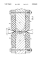
- FIG. 1 is a cross-sectional view of one embodiment of the present invention
- FIG. 2 shows the embodiment of FIG. 1 in which the jaws are closed more fully.
- FIG. 1 is a cross-sectional view of one embodiment of the present invention, wherein the jaws have two pairs of clamping elements attached thereto and wherein the jaws are slightly apart from one another.
- FIG. 2 shows the embodiment of FIG. 1 in which the jaws are closed more fully.
- first heat sealing jaw 11 and second heat sealing jaw 12 which are mounted on a form and fill machine (not shown). Both jaws may move in the directions shown by arrows A and B respectively.
- Placed on face 13 of jaw 11 is at least one layer of woven glass fibre cloth (not shown) impregnated with polytetrafluoroethylene, or other suitable material, which acts primarily as an electrical insulator and at least in part as a thermal insulator between the metal of the jaw and a heat sealing element 20.
- Second jaw 12 has a longitudinal channel 32 therein, in which is held a heat resistant resilient pad 31, e.g. a silicone rubber pad. Although not shown, it is usual to cover rubber pad 31 with a further woven glass fibre cloth impregnated with polytetrafluoroethylene.
- Jaw 11 has secured thereto resilient material, e.g. rubber clamping elements 14 and 15 and jaw 12 has secured thereto resilient material, e.g. rubber clamping elements 16 and 17.
- Clamping elements 14 and 15 are secured to jaw 11 by bolt 19 and keepers 21 and 22, and clamping elements 16 and 17 are secured to jaw 12 by bolt 18 and keepers 23 and 24.
- thermoplastic film tube 25 is passed between jaws 11 and 12.
- the film tube is collapsed transversely as jaws 11 and 12 are caused to approach one another.
- the film tube is trapped between heat seal element 20 and silicone rubber pad 31.
- the film tube 25 is trapped between the cooperating ends 26 and 27 of clamping elements 15 and 17 respectively, and between cooperating ends 28 and 29 of clamping elements 14 and 16 respectively.
- the cooperating ends of the clamping elements move towards the heat sealing element. Such movement is facilitated by the presence of the keepers and the slopes of the end faces of the clamping elements. Such movement, as shown in FIG.
- Heat is thus transferred from the hot areas of the sealed film tube, through the metallic heat sealing element 20 to jaw 11.
- the jaws are then caused to move apart in order to release the film, both by the clamping elements and by the nip between the heat sealing element 20 and pad 31.
- the seals thus formed are the top seal of a sealed pouch and the bottom seal of the next-to-be-formed pouch.
- clamping elements there are several factors which affect the performance and effectiveness, and therefore the selection, of clamping elements.
- the hardness and geometry of rubber used for the elements will affect the clamping pressure and effectiveness.
- the term “geometry” refers to the width and thickness of the rubber, the shape of the tips of the clamping elements, and any scalloping of the body of the rubber, among other things. Those skilled in the art will require to make simple experiments to determine the best hardness, geometry and positioning of the clamping elements for best effectiveness.
Abstract
Description
Claims (4)
Applications Claiming Priority (2)
| Application Number | Priority Date | Filing Date | Title |
|---|---|---|---|
| CA 2066068 CA2066068C (en) | 1992-04-15 | 1992-04-15 | Heat sealing jaw assembly |
| CA2066068 | 1992-04-15 |
Publications (1)
| Publication Number | Publication Date |
|---|---|
| US5326416A true US5326416A (en) | 1994-07-05 |
Family
ID=4149643
Family Applications (1)
| Application Number | Title | Priority Date | Filing Date |
|---|---|---|---|
| US08/045,296 Expired - Lifetime US5326416A (en) | 1992-04-15 | 1993-04-13 | Heat sealing jaw assembly with film slackener |
Country Status (5)
| Country | Link |
|---|---|
| US (1) | US5326416A (en) |
| AU (1) | AU3886093A (en) |
| CA (1) | CA2066068C (en) |
| MX (1) | MX9302190A (en) |
| WO (1) | WO1993021001A1 (en) |
Cited By (11)
| Publication number | Priority date | Publication date | Assignee | Title |
|---|---|---|---|---|
| US6612356B2 (en) | 2001-04-10 | 2003-09-02 | Exxonmobil Oil Corporation | Apparatus for improving film machinability during film sealing |
| US20040086025A1 (en) * | 2002-11-01 | 2004-05-06 | Orsini Thomas P. | Apparatus and method for controlling temperature of a film sealing element |
| US7003934B1 (en) * | 1998-10-30 | 2006-02-28 | Tetra Laval Holdings & Finance S.A. | Heat seal device |
| US20070251196A1 (en) * | 2004-04-29 | 2007-11-01 | Tetra Laval Holdings & Finance S.A. | Counter Element and Method of Producing the Same |
| US20090113852A1 (en) * | 2007-05-31 | 2009-05-07 | Philip Morris Usa Inc. | Product in seal deflection device |
| US20110114709A1 (en) * | 2009-11-17 | 2011-05-19 | Seelen A/S | Method for accumulating foil in a welding process |
| ITRM20100288A1 (en) * | 2010-05-28 | 2011-11-29 | En4En Engineering For Environment S R L | SEALER DEVICE AND SEALING UNIT. |
| WO2011148348A1 (en) * | 2010-05-28 | 2011-12-01 | En4En - Engineering For Environment S.R.L. | Bag sealer and sealing unit |
| US20160136353A1 (en) * | 2013-07-03 | 2016-05-19 | Smiths Medical Asd, Inc. | Combination linear potentiometer and syringe thumbpress detection sensor and related systems and methods |
| US9963253B2 (en) | 2011-07-11 | 2018-05-08 | Altria Client Services Llc | Air accelerator dosing tube |
| WO2020191168A1 (en) | 2019-03-19 | 2020-09-24 | Invetech, Inc. | Tube seal and cut device |
Families Citing this family (3)
| Publication number | Priority date | Publication date | Assignee | Title |
|---|---|---|---|---|
| SE501098C2 (en) * | 1993-03-02 | 1994-11-14 | Tetra Laval Holdings & Finance | Sealing device, method of making a sealing jaw and use |
| GB0126957D0 (en) | 2001-11-09 | 2002-01-02 | Bae Systems Plc | Manufacture and assembly of structures |
| DE102011015491B3 (en) * | 2011-03-29 | 2012-06-06 | Windmöller & Hölscher Kg | Method for transversely welding plastic hoses and device for forming and closing sacks |
Citations (8)
| Publication number | Priority date | Publication date | Assignee | Title |
|---|---|---|---|---|
| FR1445557A (en) * | 1965-05-07 | 1966-07-15 | Thimonnier & Cie | Further training in welding machines for making bags or other plastic objects |
| US3692613A (en) * | 1970-06-10 | 1972-09-19 | Du Pont Canada | Apparatus for sealing and cutting layers of thermoplastic film |
| US3775225A (en) * | 1971-07-06 | 1973-11-27 | Gloucester Eng Co Inc | Machine for perforating and heat sealing a web including an elongated element with a multiplicity of drivers |
| US3874976A (en) * | 1973-02-02 | 1975-04-01 | Computron Inc | Gripper jaw assembly |
| US4115182A (en) * | 1977-06-29 | 1978-09-19 | Arenco Machine Company | Sealing means |
| US4512138A (en) * | 1982-03-04 | 1985-04-23 | The Dow Chemical Company | Form, fill and seal machine with hot gas and thermal impulse sealing |
| US4744845A (en) * | 1986-09-12 | 1988-05-17 | Baxter Travenol Laboratories, Inc. | Apparatus for splicing film together |
| US4761197A (en) * | 1986-07-28 | 1988-08-02 | Baxter Travenol Laboratories, Inc. | Apparatus for sealing a web of film |
Family Cites Families (5)
| Publication number | Priority date | Publication date | Assignee | Title |
|---|---|---|---|---|
| US3536567A (en) * | 1967-08-14 | 1970-10-27 | Halm Instrument Co | Heat sealing and cooling means |
| US3846210A (en) * | 1970-12-29 | 1974-11-05 | F Groundwater | Apparatus for heat sealing thermoplastic films |
| GB1532952A (en) * | 1975-10-01 | 1978-11-22 | Metal Box Co Ltd | Attaching plastics materials to one another |
| DE2612959A1 (en) * | 1976-03-26 | 1977-10-06 | Bosch Gmbh Robert | MACHINE FOR MANUFACTURING, FILLING AND SEALING TUBE BAGS |
| US4910944A (en) * | 1989-04-12 | 1990-03-27 | J.A.D. Enterprises, Inc. | Apparatus for banding a stack of envelopes |
-
1992
- 1992-04-15 CA CA 2066068 patent/CA2066068C/en not_active Expired - Lifetime
-
1993
- 1993-04-13 US US08/045,296 patent/US5326416A/en not_active Expired - Lifetime
- 1993-04-14 WO PCT/CA1993/000161 patent/WO1993021001A1/en active Application Filing
- 1993-04-14 AU AU38860/93A patent/AU3886093A/en not_active Abandoned
- 1993-04-15 MX MX9302190A patent/MX9302190A/en unknown
Patent Citations (8)
| Publication number | Priority date | Publication date | Assignee | Title |
|---|---|---|---|---|
| FR1445557A (en) * | 1965-05-07 | 1966-07-15 | Thimonnier & Cie | Further training in welding machines for making bags or other plastic objects |
| US3692613A (en) * | 1970-06-10 | 1972-09-19 | Du Pont Canada | Apparatus for sealing and cutting layers of thermoplastic film |
| US3775225A (en) * | 1971-07-06 | 1973-11-27 | Gloucester Eng Co Inc | Machine for perforating and heat sealing a web including an elongated element with a multiplicity of drivers |
| US3874976A (en) * | 1973-02-02 | 1975-04-01 | Computron Inc | Gripper jaw assembly |
| US4115182A (en) * | 1977-06-29 | 1978-09-19 | Arenco Machine Company | Sealing means |
| US4512138A (en) * | 1982-03-04 | 1985-04-23 | The Dow Chemical Company | Form, fill and seal machine with hot gas and thermal impulse sealing |
| US4761197A (en) * | 1986-07-28 | 1988-08-02 | Baxter Travenol Laboratories, Inc. | Apparatus for sealing a web of film |
| US4744845A (en) * | 1986-09-12 | 1988-05-17 | Baxter Travenol Laboratories, Inc. | Apparatus for splicing film together |
Cited By (19)
| Publication number | Priority date | Publication date | Assignee | Title |
|---|---|---|---|---|
| US7003934B1 (en) * | 1998-10-30 | 2006-02-28 | Tetra Laval Holdings & Finance S.A. | Heat seal device |
| US6612356B2 (en) | 2001-04-10 | 2003-09-02 | Exxonmobil Oil Corporation | Apparatus for improving film machinability during film sealing |
| US20040086025A1 (en) * | 2002-11-01 | 2004-05-06 | Orsini Thomas P. | Apparatus and method for controlling temperature of a film sealing element |
| US20070251196A1 (en) * | 2004-04-29 | 2007-11-01 | Tetra Laval Holdings & Finance S.A. | Counter Element and Method of Producing the Same |
| US7640717B2 (en) * | 2004-04-29 | 2010-01-05 | Tetra Laval Holdings & Finance S.A. | Counter element and method of producing the same |
| US8402724B2 (en) * | 2007-05-31 | 2013-03-26 | Philip Morris Usa Inc. | Method and apparatus for product in seal deflection |
| US20090113852A1 (en) * | 2007-05-31 | 2009-05-07 | Philip Morris Usa Inc. | Product in seal deflection device |
| US20110114709A1 (en) * | 2009-11-17 | 2011-05-19 | Seelen A/S | Method for accumulating foil in a welding process |
| US9302428B2 (en) * | 2009-11-17 | 2016-04-05 | Seelen A/S | Method for accumulating foil in a welding process |
| WO2011148348A1 (en) * | 2010-05-28 | 2011-12-01 | En4En - Engineering For Environment S.R.L. | Bag sealer and sealing unit |
| ITRM20100288A1 (en) * | 2010-05-28 | 2011-11-29 | En4En Engineering For Environment S R L | SEALER DEVICE AND SEALING UNIT. |
| US9963253B2 (en) | 2011-07-11 | 2018-05-08 | Altria Client Services Llc | Air accelerator dosing tube |
| US11027860B2 (en) | 2011-07-11 | 2021-06-08 | Altria Client Services Llc | Delivery apparatus |
| US11618596B2 (en) | 2011-07-11 | 2023-04-04 | Altria Client Services Llc | Method of making delivery apparatus |
| US20160136353A1 (en) * | 2013-07-03 | 2016-05-19 | Smiths Medical Asd, Inc. | Combination linear potentiometer and syringe thumbpress detection sensor and related systems and methods |
| US9861740B2 (en) * | 2013-07-03 | 2018-01-09 | Smiths Medical Asd, Inc. | Combination linear potentiometer and syringe thumbpress detection sensor and related systems and methods |
| WO2020191168A1 (en) | 2019-03-19 | 2020-09-24 | Invetech, Inc. | Tube seal and cut device |
| EP3941726A4 (en) * | 2019-03-19 | 2022-12-14 | Invetech, Inc. | Tube seal and cut device |
| US11858218B2 (en) | 2019-03-19 | 2024-01-02 | Invetech, Inc. | Tube seal and cut device |
Also Published As
| Publication number | Publication date |
|---|---|
| CA2066068A1 (en) | 1993-10-16 |
| CA2066068C (en) | 2004-09-28 |
| AU3886093A (en) | 1993-11-18 |
| WO1993021001A1 (en) | 1993-10-28 |
| MX9302190A (en) | 1994-03-31 |
Similar Documents
| Publication | Publication Date | Title |
|---|---|---|
| US5247779A (en) | Self voiding jaw for packaging machine | |
| US5326416A (en) | Heat sealing jaw assembly with film slackener | |
| US4981546A (en) | Heat-sealing device for thermoplastic films | |
| CA1315665C (en) | Apparatus for sealing and severing a web of film | |
| US3692613A (en) | Apparatus for sealing and cutting layers of thermoplastic film | |
| US4964944A (en) | Apparatus for sealing and severing a web of film | |
| US5038550A (en) | Vertical form and fill machine improvements | |
| US5231817A (en) | Pouch collapsing assembly for vertical form, fill and seal machine | |
| US5355656A (en) | Heat sealing element for packaging machines which make lap-sealed pouches | |
| CA2066066C (en) | Heat sealing element for packaging machines which make lap-sealed pouches | |
| JPH0771964B2 (en) | Liquid exclusion sealing method and sealing mechanism for filling and packaging | |
| EP0573447B1 (en) | Insulated heat sealing jaw | |
| CA2691858C (en) | Heat sealing jaw, apparatus and method | |
| JPH08581B2 (en) | Sealing equipment for filling and packaging | |
| CA2129125C (en) | Heat sealing assembly for pouch-making packaging machines | |
| CA2072501A1 (en) | Pouch collapsing assembly for vertical form, fill and seal machines |
Legal Events
| Date | Code | Title | Description |
|---|---|---|---|
| STPP | Information on status: patent application and granting procedure in general |
Free format text: APPLICATION UNDERGOING PREEXAM PROCESSING |
|
| AS | Assignment |
Owner name: DU PONT CANADA INC. Free format text: ASSIGNMENT OF ASSIGNORS INTEREST;ASSIGNOR:PERRETT, ARNOLD EDWARD;REEL/FRAME:006633/0116 Effective date: 19930329 |
|
| AS | Assignment |
Owner name: DU PONT CANADA INC., CANADA Free format text: ASSIGNMENT OF ASSIGNORS INTEREST;ASSIGNOR:PERRETT, ARNOLD EDWARD;REEL/FRAME:006918/0238 Effective date: 19930329 |
|
| FPAY | Fee payment |
Year of fee payment: 4 |
|
| FPAY | Fee payment |
Year of fee payment: 8 |
|
| AS | Assignment |
Owner name: LIQUI-BOX CANADA INC., ONTARIO Free format text: ASSIGNMENT OF ASSIGNORS INTEREST;ASSIGNOR:DUPONT CANADA INC.;REEL/FRAME:014220/0507 Effective date: 20030730 |
|
| FPAY | Fee payment |
Year of fee payment: 12 |