US5322186A - Retrofit folded towel dispensing module - Google Patents
Retrofit folded towel dispensing module Download PDFInfo
- Publication number
- US5322186A US5322186A US08/075,438 US7543893A US5322186A US 5322186 A US5322186 A US 5322186A US 7543893 A US7543893 A US 7543893A US 5322186 A US5322186 A US 5322186A
- Authority
- US
- United States
- Prior art keywords
- folded
- folded towel
- dispenser
- dispensing module
- towel
- Prior art date
- Legal status (The legal status is an assumption and is not a legal conclusion. Google has not performed a legal analysis and makes no representation as to the accuracy of the status listed.)
- Expired - Lifetime
Links
Images
Classifications
-
- A—HUMAN NECESSITIES
- A47—FURNITURE; DOMESTIC ARTICLES OR APPLIANCES; COFFEE MILLS; SPICE MILLS; SUCTION CLEANERS IN GENERAL
- A47K—SANITARY EQUIPMENT NOT OTHERWISE PROVIDED FOR; TOILET ACCESSORIES
- A47K10/00—Body-drying implements; Toilet paper; Holders therefor
- A47K10/24—Towel dispensers, e.g. for piled-up or folded textile towels; Toilet-paper dispensers; Dispensers for piled-up or folded textile towels provided or not with devices for taking-up soiled towels as far as not mechanically driven
- A47K10/32—Dispensers for paper towels or toilet-paper
- A47K10/42—Dispensers for paper towels or toilet-paper dispensing from a store of single sheets, e.g. stacked
- A47K10/424—Dispensers for paper towels or toilet-paper dispensing from a store of single sheets, e.g. stacked dispensing from the bottom part of the dispenser
Definitions
- This invention relates generally to folded towel dispensers, and more particularly to retrofit module inserts for existing folded towel dispensers to allow such dispensers to dispense folded towels of different footprints.
- folded towel dispensers There are a variety of folded towel dispensers known in the prior art. It is typical of such dispensers that they are designed to dispense stacks of folded towels having a particular footprint, the footprint being the planar width and the depth of an individual folded towel in its folded configuration. Many of the existing folded towel dispensers are designed to dispense a particular fold configuration, such as C-fold or interleaved Z-fold. Further, existing towel dispensers are designed to accommodate different maximum stack heights.
- adapter plates and devices designed to be used in conjunction with existing folded towel cabinets to assist in the dispensing of towels therefrom.
- these adapter plates and devices are intended to allow the dispenser to dispense various types of towels and fold configurations.
- One such adapter plate is taught in U.S. Pat. No. 3,115,998 to Joyce, et al.
- the adapter plate is pivotally supported.
- There is a towel pack holder which first must be mounted within the dispenser.
- the adapter plate is then supported from the towel pack holder by means of a hook configuration. This allows the adapter plate to be placed in two different positions, one of the positions accommodating the dispensing of single-fold towel packs and roll towel packs, and a second position accommodating the dispensing of multi-fold towel packs.
- U.S. Pat. No. 3,028,047 to Tuft teaches another dispenser which is adapted to dispense a plurality of folded sheets of various fold configurations. This is accomplished through the provision of a plurality of bottom adapter members for a dispenser receptacle which are interchangeable with one another and which are removably engagable with a swing mounted receptacle bin in the dispenser.
- the adapters in the retrofit devices of the prior art are designed such that they are intended for installation into a specific dispenser.
- the ability to use a particular adapter or retrofit device in a dispenser for which it was not specifically designed is generally left to chance.
- some towel dispensing cabinets are designed to be recessed into bathroom walls.
- cabinet manufacturers There are a number of cabinet manufacturers, and it is practice of such cabinet manufacturers to produce a wide variety of cabinets in varying heights, widths and depths. As there is no industry standard for cabinet manufacturers to follow, there are differences between cabinets of different manufacturers. Further, there may even be differences within the same model dispenser from one manufacturer. None of the prior art adapter devices allows for an adjustable stack height such that the adapter device is designed to fit in a plurality of towel cabinets without altering the physical profile of the original cabinet, and further, without any appreciable loss of stack height capacity.
- each side panel including an extender member which is adjustable to various heights for proper positioning in towel cabinets having differing stack capacities.
- the side extenders are interconnected to a top member intended to abut the inside top surface of the existing dispenser cabinet. Pivotally mounted near or at the bottom of each side panel is a dispensing platform. Because the dispensing platform is pivotally mounted, it can assume a more appropriate position depending on the particular throat configuration of the dispenser in which the module is inserted.
- the front and rear sections of the dispensing platform where the lead and trailing towel edges usually rest may be provided with a radial or arcuate surface configuration which provides a uniform edge for a dispensed towel to clear when being dispensed.
- the radial surface areas present basically the same towel contact footprint area regardless of the pivot orientation of the dispensing platform within the folded towel cabinet.
- Each side extender member is provided with a depth locating tab that provides a means for locating the retrofit module inside towel cabinets that are greater in depth than normal from the front door to the back wall, or at least greater in depth than the depth of the dispensing module.
- the locating tabs provide a common depth for locating the front of the module top relative to the front top surface of the existing cabinet. Once the module is properly positioned and affixed in the dispenser, the locating tabs may be broken off.
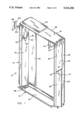
- FIG. 1 is a perspective view of retrofit folded towel dispensing module of the present invention.
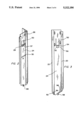
- FIG. 2 is a perspective view of the right side panel of the retrofit module of the present invention.
- FIG. 3 is a side elevation of the inside face of the right side panel of the retrofit module of the present invention.
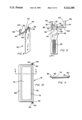
- FIG. 4 is a perspective view of the right side extender of the retrofit module of the present invention.
- FIG. 5 is a side elevation of the right side extender of the retrofit module of the present invention.
- FIG. 6 is an enlarged cross sectional view taken along line 6--6 of FIG. 5.
- FIG. 7 is a front elevational view of the top member.
- FIG. 8 is a top plan view of the top member.
- FIG. 9 is a side elevation of the top member.
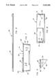
- FIG. 10 is a top plan view of the dispensing platform of the retrofit module of the present invention.
- FIG. 11 is a sectional view taken along line 11--11 of FIG. 10.
- FIG. 1 there is shown a perspective view of the retrofit folded towel dispensing module 10 of the present invention.
- Module 10 includes a left extensible side member 12, a right extensible side member 14, a top member 16 and a dispensing platform 18.
- Left extensible side member 12 and right extensible side member 14 are substantial mirror images of one another, each including a side panel or side wall 20 and a rear panel 22.
- Each extensible side member 12, 14 includes a channel 24 formed in the outside surface of side panel 20.
- Right side panel 20 is shown most clearly in FIGS. 2 and 3.
- each extensible side member 12, 14 is comprised of a side panel 20 and a side extender 26.
- Side extenders 26 are retained in channels 24 by means of tabs 28.
- each side extender 26 has a pair of shanks 32 and a key 34 extending therefrom.
- Each shank 32 has extending from the distal end thereof an interlock gib 35.
- Each key 34 is separated from shank 32 and interlock gibs 35 by slots 36.
- Each key 34 includes a guide tab 38, a shelf or bearing surface 40 and positioning or orientation nipple 42. Orientation nipple 42 extends from guide tab 38 substantially perpendicular to the inside planar surface of each key 34. The location of the orientation nipple 42 on each key 34 may be varied slightly to make distinct left and right side extenders 26 thereby ensuring proper orientation upon assembly.
- Extending from the front of each shank 32 is an L-shaped positioning member 44. There is a fracturing seam 46 where L-shaped positioning member 44 connects to the front of shank 32.
- Located on the inside surface of each side extender 26 is a plurality of recessed ratchet teeth 48 (see FIGS. 5 and 6).
- each side panel 20 Formed integrally with each side panel 20 is leaf spring 50.
- the distal end 52 of each leaf spring 50 is free or unattached.
- the inside surface of leaf spring 50 is substantially co-planar with the inside surface of side panel 20.
- Each leaf spring 50 is surrounded on three sides by U-shaped slot 54 which allows each leaf spring 50 to be flexed.
- Leaf spring 50 is preferably not as thick as side panel 20 to aid its flexibility.
- Side panel 20 includes a recess 56 opposite the distal end 52 of leaf spring 50 allowing for the insertion of the human finger therein to engage the distal end 52 to manually flex leaf spring 50.
- Extending from the outside face of leaf spring 50 adjacent side extender 26 is a projecting tooth 57.
- top member 16 preferably includes a plate 58, a locator box 60, an inclined surface 62, gussets 64, and brackets 66.
- Locator box 60 extends vertically upward from plate 58.
- first interlock slot 68 for receiving one shank 32 and one interlock gib 35.
- second interlock slot 70 for receiving the second shank 32 and interlock gib 35, and a key 34.
- Second interlock slot 70 has formed contiguously therewith orientation nipple slot 72. As with orientation nipples 42, the location of each orientation nipple slot 72 may be varied slightly to ensure proper orientation of side extenders 26 upon assembly with top member 16.
- interlock gibs 35 When assembling extensible side members 12, 14 to top member 16, interlock gibs 35 are inserted into slots 68, 70. Shanks 32 flex toward each other on insertion of interlock gibs 35 which then snap fit into place, locking side extenders 26 to top member 16, with keys 34 and positioning nipples 42 insuring proper orientation of each side extender 26 upon assembly. Bearing surfaces 40 abut each bracket 66 thereby providing support for top member 16.
- side extenders 26 For ease of assembly, it is preferable to first install side extenders 26 into channels 24. Next, dispensing platform 18 should be mounted on side panels 20. Finally, top member 16 can be attached to side extenders 26.
- Dispensing platform 18 includes dispensing opening 74 with dispensing shelf 76 thereabout.
- Dispensing platform 18 further includes a support member 78 having pins or journals 80 extending therefrom. Radially extending from journals 80 are disk members 82. Extending from the distal end of each journal 80 is one or more retaining tabs 84.
- On the opposite side of dispensing opening 74 from support member 78 is sloped lip 86. Sloped lip 86 includes an arcuate surface 88 proximate to dispensing shelf 76.
- Support member 78 also includes an arcuate surface 90 substantially along the length thereof proximate to dispensing shelf 76.
- Dispensing platform 18 is pivotally connected to extensible side members 12, 14 near the base of side panels 20.
- Side panels 20 have integrally formed therewith, near the bottom thereof, bearings 92.
- Bearings 92 may include orientation ports 94 contiguous therewith. Extending perpendicularly from side panels 20 are travel stops 96.
- journals 80 are inserted into bearings 92.
- Retaining tabs 84 insert through orientation ports 94 ensuring proper orientation of dispensing platform 18.
- Dispensing platform 18 is then pivoted upward such that the bottom thereof rests on travel stops 96.
- dispensing platform 18 When supported on travel stops 96, dispensing platform 18 will preferably reside at an angle of 90° or less relative to rear panels 22. To initially place dispensing platform 18 in this position of resting on travel stops 96, it will be necessary to slightly flex side panels 20 outward or away from one another so that dispensing platform 18 can be pivoted upward and past travel stops 96.
- Dispensing port locating fingers 98 extend from the bottom thereof. Once extensible side members 12, 14, top member 16, and dispensing platform 18 have been assembled, the module 10 can be placed within an existing dispenser. Dispensing port locating fingers 98 extend down slightly into the dispensing port of the existing dispenser thereby assuring proper alignment of dispensing opening 74 over the port of the existing dispenser.
- the module 10 is inserted into the existing wall-mounted dispenser with side extenders 26 in their fully retracted position.
- wall-mounted dispensers include any dispensers affixed to or recessed in a vertical surface.
- the installer presses upward against top member 16 thereby causing side extenders 26 to slide upward in channels 24 until locator box 60 of top member 16 contacts the upper inside surface of the existing dispenser. Because of the interlocking fit of projecting tooth 57 on each leaf spring 50 with recessed ratchet teeth 48, the sliding movement of side extenders 26 within channels 24 is one directional allowing for an incremental or ratchet-like movement until the proper or desired height is reached.
- the side extenders 26, recess 56 allows for the insertion of a human finger to engage the bottom of leaf spring 50 to thereby flex leaf spring 50 toward the inside of module 10 thereby causing projecting tooth 57 to disengage from recessed ratchet teeth 48.
- side extenders 26 can slide in a downward direction within channels 24.
- Positioning members or depth locating tabs 44 extending from side extenders 26 ensure that module 10 can be properly oriented within towel dispensing cabinets which are relatively deep from the front door of the cabinet to the back wall.
- the locating tabs 44 provide a common depth for locating the front of the module 10 relative to the top front surface of the existing cabinet.
- depth locating tabs 44 projects outside the dispenser cabinet.
- vertical section 102 of depth locating tab 44 is positioned such that its inner edge 104 abuts the upper front surface of the existing cabinet.
- the dispensing platform 18 pivots around journals 80 residing within bearings 92. This allows the dispensing platform 18 to adjust to the various folded towel cabinet dispensing throat configuration.
- the dispensing platform angle of the existing dispensing cabinet can vary from dispenser to dispenser.
- the sloped lip 86 of the dispensing platform 18 includes the previously mentioned arcuate surface 88, or the support member 78 includes the arcuate surface 90. Most preferably, both arcuate surfaces 88, 90 are present. Arcuate surfaces 88, 90 present basically the same towel contact footprint area regardless of the position of the dispensing platform 18 within the folded towel cabinet.
- the top member 16 of module 10 includes the previously mentioned inclined surface 62.
- the position of the inclined surface will discourage the over stuffing of towels within module 10. Over stuffing can cause various types of dispensing failures, most commonly jamming. When the stack is under pressure due to over stuffing, dispensing of a single towel becomes difficult, if not impossible.
- the presence of inclined surface limits those maintaining the dispenser from overfilling by not providing a bearing surface perpendicular to the stack. Since the inclined surface 62 is integrally formed as part of the top member, inclined surface 62 adjusts to near the full height of the existing cabinet as part of top member 16.
- locator tabs 44 are discussed herein as extending from side extenders 26, it should be appreciated that similar depth tabs could extend from top member 16 to achieve the same purpose.
- top member 16 with its above described features, is integrally formed. Also integrally formed would be the dispensing platform 18, as would each side panel 20, and each side extender 26.
Abstract
Description
Claims (15)
Priority Applications (1)
| Application Number | Priority Date | Filing Date | Title |
|---|---|---|---|
| US08/075,438 US5322186A (en) | 1993-06-14 | 1993-06-14 | Retrofit folded towel dispensing module |
Applications Claiming Priority (1)
| Application Number | Priority Date | Filing Date | Title |
|---|---|---|---|
| US08/075,438 US5322186A (en) | 1993-06-14 | 1993-06-14 | Retrofit folded towel dispensing module |
Publications (1)
| Publication Number | Publication Date |
|---|---|
| US5322186A true US5322186A (en) | 1994-06-21 |
Family
ID=22125757
Family Applications (1)
| Application Number | Title | Priority Date | Filing Date |
|---|---|---|---|
| US08/075,438 Expired - Lifetime US5322186A (en) | 1993-06-14 | 1993-06-14 | Retrofit folded towel dispensing module |
Country Status (1)
| Country | Link |
|---|---|
| US (1) | US5322186A (en) |
Cited By (11)
| Publication number | Priority date | Publication date | Assignee | Title |
|---|---|---|---|---|
| US6003723A (en) * | 1997-09-02 | 1999-12-21 | Perrin Manufacturing | Large capacity towel dispenser |
| US6189726B1 (en) | 1999-05-06 | 2001-02-20 | Binkowsky, Inc. | Towel dispenser adapter |
| US20020070228A1 (en) * | 2000-12-11 | 2002-06-13 | Moody John R. | Modified gravity-feed multi-fold towel dispenser |
| NL2002563C2 (en) * | 2009-02-25 | 2010-08-26 | Houtum Papier B V Van | Paper towel dispenser. |
| EP0910273B2 (en) † | 1996-07-12 | 2011-05-11 | Georgia-Pacific S.A.R.L. | Paper dispenser containing a removable case |
| US20120267387A1 (en) * | 2009-09-22 | 2012-10-25 | Paul Omdoll | Transformable Dispenser |
| US20140014675A1 (en) * | 2011-03-29 | 2014-01-16 | Sca Hygiene Products Ab | Hygienic container |
| WO2014200394A1 (en) * | 2013-06-10 | 2014-12-18 | Sca Hygiene Products Ab | Dispenser for a stack of web material |
| USD784039S1 (en) | 2015-10-16 | 2017-04-18 | Kimberly-Clark Worldwide, Inc. | Paper product dispenser |
| USD790873S1 (en) | 2015-12-28 | 2017-07-04 | Kimberly-Clark Worldwide, Inc. | Multi-fold towel dispenser |
| US20220133100A1 (en) * | 2019-03-11 | 2022-05-05 | Essity Hygiene And Health Aktiebolag | Dispenser for dispensing sheet products |
Citations (6)
| Publication number | Priority date | Publication date | Assignee | Title |
|---|---|---|---|---|
| US1724428A (en) * | 1925-09-09 | 1929-08-13 | Brown Co | Holder for paper towels and the like |
| DE1289274B (en) * | 1965-07-17 | 1969-02-13 | Waldhof Zellstoff Fab | Storage container for material web sections |
| US3713561A (en) * | 1970-11-30 | 1973-01-30 | G Wyant | Cabinet for selectively dispensing different types of paper towels |
| GB2195987A (en) * | 1986-09-23 | 1988-04-20 | K R G Precision Limited | Dispensing device |
| US4768679A (en) * | 1985-02-19 | 1988-09-06 | Sumio Matsui | Dispensing container for paper tissues and the like |
| US4811878A (en) * | 1987-01-14 | 1989-03-14 | Twin-Cee Limited | Universal towel dispenser |
-
1993
- 1993-06-14 US US08/075,438 patent/US5322186A/en not_active Expired - Lifetime
Patent Citations (6)
| Publication number | Priority date | Publication date | Assignee | Title |
|---|---|---|---|---|
| US1724428A (en) * | 1925-09-09 | 1929-08-13 | Brown Co | Holder for paper towels and the like |
| DE1289274B (en) * | 1965-07-17 | 1969-02-13 | Waldhof Zellstoff Fab | Storage container for material web sections |
| US3713561A (en) * | 1970-11-30 | 1973-01-30 | G Wyant | Cabinet for selectively dispensing different types of paper towels |
| US4768679A (en) * | 1985-02-19 | 1988-09-06 | Sumio Matsui | Dispensing container for paper tissues and the like |
| GB2195987A (en) * | 1986-09-23 | 1988-04-20 | K R G Precision Limited | Dispensing device |
| US4811878A (en) * | 1987-01-14 | 1989-03-14 | Twin-Cee Limited | Universal towel dispenser |
Cited By (12)
| Publication number | Priority date | Publication date | Assignee | Title |
|---|---|---|---|---|
| EP0910273B2 (en) † | 1996-07-12 | 2011-05-11 | Georgia-Pacific S.A.R.L. | Paper dispenser containing a removable case |
| US6003723A (en) * | 1997-09-02 | 1999-12-21 | Perrin Manufacturing | Large capacity towel dispenser |
| US6189726B1 (en) | 1999-05-06 | 2001-02-20 | Binkowsky, Inc. | Towel dispenser adapter |
| US20020070228A1 (en) * | 2000-12-11 | 2002-06-13 | Moody John R. | Modified gravity-feed multi-fold towel dispenser |
| US7845515B2 (en) * | 2000-12-11 | 2010-12-07 | Georgia-Pacific Consumer Products Lp | Modified gravity-feed multi-fold towel dispenser |
| NL2002563C2 (en) * | 2009-02-25 | 2010-08-26 | Houtum Papier B V Van | Paper towel dispenser. |
| US20120267387A1 (en) * | 2009-09-22 | 2012-10-25 | Paul Omdoll | Transformable Dispenser |
| US20140014675A1 (en) * | 2011-03-29 | 2014-01-16 | Sca Hygiene Products Ab | Hygienic container |
| WO2014200394A1 (en) * | 2013-06-10 | 2014-12-18 | Sca Hygiene Products Ab | Dispenser for a stack of web material |
| USD784039S1 (en) | 2015-10-16 | 2017-04-18 | Kimberly-Clark Worldwide, Inc. | Paper product dispenser |
| USD790873S1 (en) | 2015-12-28 | 2017-07-04 | Kimberly-Clark Worldwide, Inc. | Multi-fold towel dispenser |
| US20220133100A1 (en) * | 2019-03-11 | 2022-05-05 | Essity Hygiene And Health Aktiebolag | Dispenser for dispensing sheet products |
Similar Documents
| Publication | Publication Date | Title |
|---|---|---|
| US5322186A (en) | Retrofit folded towel dispensing module | |
| US5100020A (en) | Folded sheet product dispenser system | |
| CA2574266C (en) | Gravity-feed napkin dispenser with internal blocking assembly | |
| AU2006332671B2 (en) | Paper towel cabinet with paper towel support bar | |
| US7891503B2 (en) | Product management display system | |
| CA2339267C (en) | Folded sheet adapter | |
| US20140175035A1 (en) | Product Management Display System | |
| AU2015263424B2 (en) | Paper product dispenser and related methods | |
| US20020179630A1 (en) | Container for dispensing controlled amounts of paper products | |
| US5765719A (en) | Roll dispenser and rack | |
| US20230249932A1 (en) | Dispensing assembly for selectively dispensing a plurality of supplies of rolled sheet material | |
| CA2461760C (en) | Interfolded towel dispenser | |
| US6406107B1 (en) | Gravity feed multiple sized and shaped package display dispenser | |
| US5156293A (en) | Folded sheet product dispenser system | |
| US7845515B2 (en) | Modified gravity-feed multi-fold towel dispenser | |
| CA2310653C (en) | Container and cartridge for dispensing paper products | |
| EP3564908B1 (en) | Lottery ticket dispenser bin with pivotal door | |
| US3329366A (en) | Multiple paper roll dispenser | |
| US3840146A (en) | Paper towel dispenser | |
| US6220332B1 (en) | Door assembly for spanning an entrance of a shower room | |
| US3381852A (en) | Paper towel dispensing cabinet | |
| EP0506244A1 (en) | Folded sheet product dispenser system | |
| GB2351073A (en) | Dispensing device for articles such as newspapers | |
| IE52924B1 (en) | A product dispenser | |
| CZ20002234A3 (en) | Storage container and cassette for feeding paper products |
Legal Events
| Date | Code | Title | Description |
|---|---|---|---|
| STPP | Information on status: patent application and granting procedure in general |
Free format text: APPLICATION UNDERGOING PREEXAM PROCESSING |
|
| AS | Assignment |
Owner name: SCOTT PAPER COMPANY, PENNSYLVANIA Free format text: ASSIGNMENT OF ASSIGNORS INTEREST;ASSIGNORS:FRAZIER, ALAN D.;KLEY, RICHARD D.;REEL/FRAME:006621/0342 Effective date: 19930609 |
|
| FPAY | Fee payment |
Year of fee payment: 4 |
|
| AS | Assignment |
Owner name: KIMBERLY-CLARK TISSUE COMPANY, WISCONSIN Free format text: CHANGE OF NAME;ASSIGNOR:SCOTT PAPER COMPANY;REEL/FRAME:010648/0800 Effective date: 20000223 |
|
| FPAY | Fee payment |
Year of fee payment: 8 |
|
| AS | Assignment |
Owner name: KIMBERLY-CLARK WORLDWIDE, INC., WISCONSIN Free format text: ASSIGNMENT OF ASSIGNORS INTEREST;ASSIGNOR:KIMBERLY-CLARK TISSUE COMPANY;REEL/FRAME:013746/0175 Effective date: 20030207 |
|
| FPAY | Fee payment |
Year of fee payment: 12 |