US5318138A - Adjustable stabilizer - Google Patents
Adjustable stabilizer Download PDFInfo
- Publication number
- US5318138A US5318138A US07/965,347 US96534792A US5318138A US 5318138 A US5318138 A US 5318138A US 96534792 A US96534792 A US 96534792A US 5318138 A US5318138 A US 5318138A
- Authority
- US
- United States
- Prior art keywords
- blades
- stabilizer
- adjustable
- piston
- adjustable blade
- Prior art date
- Legal status (The legal status is an assumption and is not a legal conclusion. Google has not performed a legal analysis and makes no representation as to the accuracy of the status listed.)
- Expired - Lifetime
Links
- 239000003381 stabilizer Substances 0.000 title claims abstract description 108
- 238000005553 drilling Methods 0.000 claims abstract description 39
- 230000004044 response Effects 0.000 claims abstract description 5
- 239000012530 fluid Substances 0.000 claims description 14
- 230000000670 limiting effect Effects 0.000 claims description 3
- 230000000452 restraining effect Effects 0.000 claims 3
- 238000005259 measurement Methods 0.000 abstract description 6
- 238000000034 method Methods 0.000 description 14
- 230000015572 biosynthetic process Effects 0.000 description 10
- 230000006641 stabilisation Effects 0.000 description 7
- 238000011105 stabilization Methods 0.000 description 7
- 238000004891 communication Methods 0.000 description 5
- 230000006870 function Effects 0.000 description 5
- 230000005540 biological transmission Effects 0.000 description 4
- 230000008859 change Effects 0.000 description 3
- 238000010276 construction Methods 0.000 description 3
- 238000012937 correction Methods 0.000 description 3
- 238000005520 cutting process Methods 0.000 description 3
- 230000003247 decreasing effect Effects 0.000 description 3
- 230000007246 mechanism Effects 0.000 description 3
- 230000008569 process Effects 0.000 description 3
- 230000004913 activation Effects 0.000 description 2
- 238000012856 packing Methods 0.000 description 2
- WHXSMMKQMYFTQS-UHFFFAOYSA-N Lithium Chemical compound [Li] WHXSMMKQMYFTQS-UHFFFAOYSA-N 0.000 description 1
- 101100386054 Saccharomyces cerevisiae (strain ATCC 204508 / S288c) CYS3 gene Proteins 0.000 description 1
- 230000000712 assembly Effects 0.000 description 1
- 238000000429 assembly Methods 0.000 description 1
- 230000001186 cumulative effect Effects 0.000 description 1
- 238000013461 design Methods 0.000 description 1
- 238000010586 diagram Methods 0.000 description 1
- 238000005516 engineering process Methods 0.000 description 1
- 238000011156 evaluation Methods 0.000 description 1
- 239000010720 hydraulic oil Substances 0.000 description 1
- 230000002452 interceptive effect Effects 0.000 description 1
- 229910052744 lithium Inorganic materials 0.000 description 1
- 238000012986 modification Methods 0.000 description 1
- 230000004048 modification Effects 0.000 description 1
- 239000003921 oil Substances 0.000 description 1
- 230000036961 partial effect Effects 0.000 description 1
- 230000035515 penetration Effects 0.000 description 1
- 230000000737 periodic effect Effects 0.000 description 1
- 230000036316 preload Effects 0.000 description 1
- 230000002829 reductive effect Effects 0.000 description 1
- 230000000717 retained effect Effects 0.000 description 1
- 125000006850 spacer group Chemical group 0.000 description 1
- 101150035983 str1 gene Proteins 0.000 description 1
- 230000001960 triggered effect Effects 0.000 description 1
Images


Classifications
-
- E—FIXED CONSTRUCTIONS
- E21—EARTH DRILLING; MINING
- E21B—EARTH DRILLING, e.g. DEEP DRILLING; OBTAINING OIL, GAS, WATER, SOLUBLE OR MELTABLE MATERIALS OR A SLURRY OF MINERALS FROM WELLS
- E21B17/00—Drilling rods or pipes; Flexible drill strings; Kellies; Drill collars; Sucker rods; Cables; Casings; Tubings
- E21B17/10—Wear protectors; Centralising devices, e.g. stabilisers
- E21B17/1014—Flexible or expansible centering means, e.g. with pistons pressing against the wall of the well
Definitions
- the present invention relates generally to a steerable system for controlling borehole deviation with respect to the vertical axis by varying the angle of such deviation without removing (tripping) the system from the borehole, and more particularly to a directional drilling apparatus that is remotely adjustable or variable during operation for affecting deviation control.
- a steerable system is one that controls borehole deviation without being required to be withdrawn from the borehole during the drilling operation.
- the typical steerable system today comprises a downhole motor having a bent housing, a fixed diameter near bit stabilizer on the lower end of the motor housing, a second fixed diameter stabilizer above the motor housing and an MWD (measurement-while-drilling) system above that.
- a lead collar of about three to ten feet is sometimes run between the motor and the second stabilizer.
- Such a system is typically capable of building, dropping or turning about three to eight degrees per 100 feet when sliding, i.e. just the motor output shaft is rotating the drill bit while the drill string remains rotationally stationary.
- the goal is usually for the system to simply hold angle (zero build rate), but variations in hole conditions, operating parameters, wear on the assembly, etc.
- the first option is to make periodic corrections by sliding the system part of the time.
- the second option is to trip the assembly and change the lead collar length or, less frequently, the diameter of the second stabilizer to fine tune the rotating mode build rate.
- One potential problem with the first option is that when sliding, sharp angle changes referred to as doglegs and ledges may be produced, which increase torque and drag on the drill string, thereby reducing drilling efficiencies and capabilities. Moreover, the rate of penetration for the system is lower during the sliding mode.
- the problem with the second option is the costly time it takes to trip. In addition, the conditions which prevented the assembly from holding angle may change again, thus requiring additional sliding or another trip.
- the Andergage is commercially available and is described in U.S. Pat. No. 4,848,490.
- This stabilizer adjusts a half-inch diametrically, and when run above a steerable motor, is capable of inclination corrections on the order of ⁇ one-half a degree per 100 feet, when rotating.
- This tool is activated by applying weight to the assembly and is locked into position by the flow of the drilling fluid. This means of communication and actuation essentially limits the number of positions to two, i.e. extended and retracted.
- This tool has an additional operational disadvantage in that it must be reset each time a connection is made during drilling.
- Andergage Another limitation of the Andergage is that its one-half inch range of adjustment may be insufficient to compensate for the cumulative variations in drilling conditions mentioned above. As a result, it may be necessary to continue to operate in the sliding mode.
- the Andergage is currently being run as a near-bit stabilizer in rotary-only applications, and as a second stabilizer (above the bent motor housing) in a steerable system.
- the operational disadvantages mentioned above have prevented its widespread use.
- Varistab Another adjustable or variable stabilizer, the Varistab, has seen very limited commercial use.
- This stabilizer is covered by the following U.S. Pat. Nos. 4,821,817; 4,844,178; 4,848,488; 4,951,760; 5,065,825; and 5,070,950.
- This stabilizer may have more than two positions, but the construction of the tool dictates that it must index through these positions in order.
- the gauge of the stabilizer remains in a given position, regardless of flow status, until an actuation cycle drives the blades of the stabilizer to the next position.
- the blades are driven outwardly by a ramped mandrel, and no external force in any direction can force the blade to retract.
- This is an operational disadvantage. If the stabilizer were stuck in a tight hole and were in the middle position, it would be difficult to advance it through the largest extended position to return to the smallest. Moreover, no amount of pipe movement would assist in driving the blades back.
- the source of power for indexing the blades is the increased internal pressure drop which occurs when the flow threshold is exceeded. It is this actuation method that dictates that the blades remain in position even after flow is reduced.
- the use of an internal pressure drop to hold blades in position (as opposed to driving them there and leaving them locked in position) would require a constant pressure restriction, which would even be more undesirable.
- the pressure spike does not uniquely identify the position which has been reached.
- the driller therefore, is required to keep track of pressure spikes in order to determine the position of the stabilizer blades.
- complications arise because conditions such as motor stalling, jets plugging, and cuttings building up in the annulus, all can create pressure spikes which may give false indications.
- the Varistab has had minimal commercial success due to its operational limitations.
- U.S. Pat. No. 4,572,305 Another adjustable stabilizer recently commercialized is shown in U.S. Pat. No. 4,572,305. It has four straight blades that extend radially three or four positions and is set by weight and locked into position by flow. The amount of weight on bit before flow initiates will dictate blade position. The problem with this configuration is that in directional wells, it can be very difficult to determine true weight-on-bit and it would be hard to get this tool to go to the right position with setting increments of only a few thousand pounds per position.
- adjustable stabilizers to have a greater impact on directional drilling can generally be attributed to either lack of ruggedness, lack of sufficient change in diameter, inability to positively identify actual diameter, or setting procedures which interfere with the normal drilling process.
- the present invention obviates the above-mentioned shortcomings in the prior art by providing an adjustable or variable stabilizer system having the ability to actuate the blades of the stabilizer to multiple positions and to communicate the status of these positions back to the surface, without significantly interfering with the drilling process.
- the adjustable stabilizer in accordance with the present invention, comprises two basic sections, the lower power section and the upper control section.
- the power section includes a piston for expanding the diameter of the stabilizer blades.
- the piston is actuated by the pressure differential between the inside and the outside of the tool.
- a positioning mechanism in the upper body serves to controllably limit the axial travel of a flow tube in the lower body, thereby controlling the radial extension of the blades.
- the control section comprises novel structure for measuring and verifying the location of the positioning mechanism.
- the control section further comprises an electronic control unit for receiving signals from which position commands may be derived.
- a microprocessor or microcontroller preferably is provided for encoding the measured position into time/pressure signals for transmission to the surface whereby these signals identify the position.
- FIG. 1A is a sectional view of the lower section of the adjustable stabilizer according to the present invention.
- FIG. 1B is a sectional view of the upper section of the adjustable stabilizer of the present invention.
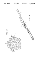
- FIG. 2 is a sectional view taken along lines 2--2 of FIG. 1A;
- FIG. 3 is an elevational view of the lower section taken along lines 3--3 of FIG. 1A;
- FIG. 4 is an elevational view showing a stabilizer blade and the push and follower rod assemblies utilized in the embodiment shown in FIG. 1A;
- FIG. 5 is an elevational view of one embodiment of a bottom hole assembly utilizing the adjustable stabilizer
- FIG. 6 is an elevational view of a second embodiment of a bottom hole assembly utilizing the adjustable stabilizer of the present invention.
- FIG. 7 is a flow chart illustrating operation of an automatic closed loop drilling system for drilling in a desired formation using the adjustable stabilizer of the present invention
- FIG. 8 is a flow chart illustrating the operation of an automatic closed loop drilling system for drilling in a desired direction using the adjustable stabilizer of the present invention
- FIGS. 9A-9C illustrating the combined time/pulse encoding technique used in the preferred embodiment of the present invention to encode stabilizer position data.
- FIGS. 1A and 1B illustrate an adjustable stabilizer, generally indicated by arrow 10, having a power section 11 and a control section 40.
- the power section 11 comprises an outer tubular body 12 having an outer diameter approximately equal to the diameter of the drill collars and other components located on the lower drill string forming the bottom hole assembly.
- the tubular body 12 is hollow and includes female threaded connections 13 located at its ends for connection to the pin connections of the other bottom hole assembly components.
- the middle section of the tubular body 12 has five axial blade slots 14 radially extending through the outer body and equally spaced around the circumference thereof. Although five slots are shown, any number of blades could be utilized.
- Each slot 14 further includes a pair of angled blade tracks 15 or guides which are formed in the body 12. These slots could also be formed into separate plates to be removably fitted into the body 12. The function of these plates would be to keep the wear localized in the guides and not on the body.
- a plurality of blades 17 are positioned within the slots 14 with each blade 17 having a pair of slots 18 formed on both sides thereof for receiving the projected blades tracks 15. It should be noted that the tracks 15 and the corresponding blade slots 18 are slanted to cause the blades 17 to move axially upward as they move radially outward.
- a multi-sectioned flow tube 20 extends through the interior of the outer tubular body 12.
- the central portion 21 of the flow tube 20 is integrally formed with the interior of the tubular body 12.
- the lower end of the flow tube 20 comprises a tube section 22 integrally mounted to the central portion 21.
- the upper end of the flow tube 20 comprises a two piece tube section 23 with the lower end thereof being slidingly supported within the central portion 21.
- the upper end of the tube section 23 is slidingly supported within a spacer rib or bushing 24.
- Appropriate seals 122 are provided to prevent the passage of drilling fluid flow around the tube section 23.
- the tube section 22 axially supports an annular drive piston 25.
- the outer diameter of the piston 25 slidingly engages an interior cylindrical portion 26 of the body 12.
- the inner diameter of the piston 25 slidingly engages the tube section 22.
- the piston 25 is responsive to the pressure differential between the flow of the drilling fluid down through the interior of the stabilizer 10 and the flow of drilling fluid passing up the annulus formed by the borehole and the outside of the tube 12.
- Ports 29 are located on the body 12 to provide fluid communication between the borehole annulus and the interior of the body 12. Seals 27 are provided to prevent drilling fluid flow upwardly past the piston 25.
- the cylindrical chamber 26 and the blade slot 14 provide a space for receiving push rods 30.
- the lower end of each push rod 30 abuts against the piston 25.
- the upper end of each push rod 30 is enlarged to abut against the lower side of a blade 17.
- the lower end faces of the blades 17 are angled to match an angled face of the push rod upper end to force the blades 14 against one side of the pocket to maintain contact therewith (see FIG. 4). This prevents drilled cuttings from packing between the blades and pockets and causing vibration and abrasive or fretting type wear.
- each follower rod 35 extends into an interior chamber 36 and is adapted to abut against an annular projection 37 formed on the tube section 23.
- a return spring 39 is also located within chamber 36 and is adapted to abut against the upper side of the projection 37 and the lower side of the bushing 24.
- the upper end of the flow tube 23 further includes a plurality of ports 38 to enable drilling fluid to pass downwardly therethrough.
- FIG. 1B further illustrates the control section 40 of the adjustable stabilizer 10.
- the control section 40 comprises an outer tubular body 41 having an outer diameter approximately equal to the diameter of body 12.
- the lower end of the body 41 includes a pin 42 which is adapted to be threadedly connected to the upper box connection 13 of the body 12.
- the upper end of the body 41 comprises a box section 43.
- the control section 40 further includes a connector sub 45 having pins 46 and 47 formed at its ends.
- the lower pin 46 is adapted to be threadedly attached to the box 43 while the upper pin 47 is adapted to be threadedly connected to another component of the drill string or bottom assembly which may be a commercial MWD system.
- the tubular body 41 forms an outer envelope for an interior tubular body 50.
- the body 50 is concentrically supported within the tubular body 41 at its ends by support rings 51.
- the support rings 51 are ported to allow drilling fluid flow to pass into the annulus 52 formed between the two bodies.
- the lower end of tubular body 50 slidingly supports a positioning piston 55, the lower end of which extends out of the body 50 and is adapted to engage the upper end of the flow tube 23.
- the interior of the piston 55 is hollow in order to receive an axial position sensor 60.
- the position sensor 60 comprises two telescoping members 61 and 62.
- the lower member 62 is connected to the piston 55 and is further adapted to travel within the first member 61. The amount of such travel is electronically sensed in the conventional manner.
- the position sensor 60 is preferably a conventional linear potentiometer and can be purchased from a company such as Subminiature Instruments Corporation, 950 West Kershaw, Ogden, Utah 84401.
- the upper member 61 is attached to a bulkhead 65 which is fixed within the tubular body 50.
- the bulkhead 65 has a solenoid operated valve and passage 66 extending therethrough.
- the bulkhead 65 further includes a pressure switch and passage 67.
- a conduit tube (not shown) is attached at its lower end to the bulkhead 65 and at its upper end to and through a second bulkhead 69 to provide electrical communication for the position sensor 60, the solenoid valve 66, and the pressure switch 67, to a battery pack 70 located above the second bulkhead 69.
- the batteries preferably are high temperature lithium batteries such as those supplied by Battery Engineering, Inc., of Hyde Park, Mass.
- a compensating piston 71 is slidingly positioned within the body 50 between the two bulkheads.
- a spring 72 is located between the piston 71 and the second bulkhead 69, and the chamber containing the spring is vented to allow the entry of drilling fluid.
- the connector sub 45 functions as an envelope for a tube 75 which houses a microprocessor 101 and power regulator 76.
- the microprocessor 101 preferably comprises a Motorola M68HC11, and the power regulator 76 may be supplied by Quantum Solutions, Inc., of Santa Clara, Calif. Electrical connections 77 are provided to interconnect the power regulator 76 to the battery pack 70.
- a data line connector 78 is provided with the tube 75 for interconnecting the microprocessor 101 with the measurement-while-drilling (MWD) sub 84 located above the stabilizer 10 (FIG. 6).
- MWD measurement-while-drilling
- the stabilizer 10 functions to have its blades 17 extend or retract to a number of positions on command.
- the power source for moving the blades 17 comprises the piston 25, which is responsive to the pressure differential existing between the inside and the outside of the tool.
- the pressure differential is due to the flow of drilling fluid through the bit nozzles and downhole motor, and is not generated by any restriction in the stabilizer itself.
- This pressure differential drives the piston 25 upwardly, driving the push rods 30 which in turn drive the blades 17. Since the blades 17 are on angled tracks 15, they expand radially as they travel axially.
- the follower rods 35 travel with the blades 17 and drive the flow tube 23 axially.
- the axial movement of the flow tube 23 is limited by the positioning piston 55 located in the control section 40. Limiting the axial travel of the flow tube 23 limits the radial extension of the blades 17.
- the end faces of the blades 17 are angled to force the blades to maintain contact with one side of the blade pocket (in the direction of the rotationally applied load), thereby preventing drilled cuttings from packing between the blade and pocket and causing increased wear.
- the blade slots 14 communicate with the body cavity 12 only at the ends of each slot, leaving a tube (see FIG. 2), integral to the body and to the side walls of each slot, to transmit flow through the pocket area.
- the control section there are three basic components: hydraulics, electronics, and a mechanical spring.
- the hydraulic section there are basically two reservoirs, defined by the positioning piston 55, the bulkhead 65, and the compensating piston 71.
- the spring 72 exerts a force on the compensating piston 71 to influence hydraulic oil to travel through the bulkhead passage and extend the positioning system.
- the solenoid operated valve 66 in the bulkhead 65 prevents the oil from transferring unless the valve is open.
- the positioning piston 55 will extend when flow of drilling mud is off, i.e. no force is being exerted on the positioning piston 55 by the flow tube 23.
- To retract the piston 55 the valve 66 is held open when drilling mud is flowing.
- the annular piston 25 in the lower power section 11 then actuates and the flow tube 22 forces the positioning piston 55 to retract.
- the position sensor 60 measures the extension of the positioning piston 55.
- the microcontroller 101 monitors this sensor and closes the solenoid valve 66 when the desired position has been reached.
- the differential pressure switch 67 in the bulkhead 65 verifies that the flow tube 23 has made contact with the positioning piston 55. The forces exerted on the piston 55 causes a pressure increase on that side of the bulkhead.
- the spring preload on the compensating piston 71 insures that the pressure in the hydraulic section is equal to or greater than downhole pressure to minimize the possibility of mud intrusion into the hydraulic system.
- a conventional single pin wet-stab connector 78 is the data line communication between the stabilizer and MWD (measurement while drilling) system.
- the location of positioning piston 55 is communicated to the MWD and encoded into time/pressure signals for transmission to the surface.
- FIG. 5 illustrates the adjustable stabilizer 10 in a steerable bottom hole assembly that operates in the sliding and rotational mode.
- This assembly preferably includes a downhole motor 80 having at least one bend and a stabilization point 81 located thereon.
- a conventional concentric stabilizer 82 is shown, pads, eccentric stabilizers, enlarged sleeves or enlarged motor housing may also be utilized as the stabilization point.
- the adjustable stabilizer 10, substantially as shown in FIGS. 1 through 4 preferably is used as the second stabilization point for fine tuning inclination while rotating. Rapid inclination and/or azimuth changes are still achieved by sliding the bent housing motor.
- the bottom hole assembly also utilizes a drill bit 83 located at the bottom end thereof and a MWD unit 84 located above the adjustable stabilizer.
- FIG. 6 illustrates a second bottom hole assembly in which the adjustable stabilizer 10, as disclosed herein, preferably is used as the first stabilization point directly above the bit 83. In this configuration, a bent steerable motor is not used. This system preferably is run in the rotary mode.
- the second stabilizer 85 also may be an adjustable stabilizer or a conventional fixed stabilizer may be used.
- an azimuth controller also can be utilized as the second stabilization point, or between the first and second stabilization points. An example of such an azimuth controller is shown in U.S. Pat. No. 3,092,188, the teachings of which are incorporated by reference herein.
- a drill collar is used to space out the first and second stabilizers.
- the drill collar may contain formation evaluation sensors 88 such as gamma and/or resistivity.
- An MWD unit 84 preferably is located above the second stabilization point.
- geological formation measurements may be used as the basis for stabilizer adjustment decisions. These decisions may be made at the surface and communicated to the tool through telemetry, or may be made downhole in a closed loop system, using a method such as that shown in FIG. 7.
- surface commands may be used interactively with a closed loop system. For example, surface commands setting a predetermined range of formation characteristics (such as resistivity ranges or the like) may be transmitted to the microcontroller, once a particular formation is entered. The actual predetermined range of characteristics may be transmitted from the surface, or various predetermined ranges of characteristics may be preprogrammed in the microcontroller and selected by a command from the surface. Once the range is determined, the microcontroller then implements the automatic closed loop system as shown in FIG. 7 to stay within the desired formation.
- a predetermined range of formation characteristics such as resistivity ranges or the like
- the stabilizer diameter can be adjusted to allow the assembly to re-enter that formation.
- a similar geological steering method is generally disclosed in U.S. Pat. No. 4,905,774, in which directional steering in response to geological inputs is accomplished with a turbine and controllable bent member in some undisclosed fashion.
- the use of the adjustable blade stabilizer, as disclosed herein makes it possible to achieve directional control in a downhole assembly, without the necessity of surface commands and without the directional control being accomplished through the use of a bent member.
- the MWD system customarily has a flow switch (not shown) which currently informs the MWD system of the flow status of the drilling fluid (on/off) and triggers the powering up of sensors.
- Timed flow sequences are also used to communicate various commands from the surface to the MWD system. These commands may include changing various parameters such as survey data sent, power usage levels, and so an.
- the current MWD system is customarily programmed so that a single "short cycle" of the pump (flow on for less than 30 seconds) tells the MWD to "sleep", or to not acquire a survey.
- the stabilizer as disclosed herein preferably is programmed to look for two consecutive "short cycles" as the signal that a stabilizer repositioning command is about to be sent. The duration of flow after the two short cycles will communicate the positioning command. For example, if the stabilizer is programmed for 30 seconds per position, two short cycles followed by flow which terminates between 90 and 120 seconds would mean position three.
- the timing parameters preferably are programmable and are specified in seconds.
- the settings are stored in non-volatile memory and are retained when module power is removed.
- a command cycle preferably comprises two parts.
- the flow In order to be considered a valid command, the flow must remain on for at least TZro seconds. This corresponds to position zero. Every increment of length TCmd that the flow remains on after TZro indicates one increment in commanded position. (Currently, if the flow remains on more than 256 seconds during the command cycle, the command will be aborted. This maximum time may be increased, if necessary).
- the desired position is known. Referring to FIGS. 1 through 4, if the position is increasing the solenoid valve 66 is activated to move positioning piston 55, thereby allowing decreased movement of the annular drive piston 25. The positioning piston 55 is locked when the new position is reached. If the position is decreasing, the solenoid valve 66 is activated before mud flow begins again, but is not deactivated until the flow tube 23 drives the positioning piston 55 to retract to the desired position. When flow returns, the positioning piston 55 is forced back to the new position and locked. Thus after the repositioning command is received, the positioning piston 55 is set while flow is off. When flow resumes, the blades 17 expand to the new position by the movement of drive piston 25.
- the blades 17 When making a drill string connection, the blades 17 will collapse because no differential pressure exists when flow is off and thus drive piston 25 is at rest. If no repositioning command has been sent, the positioning piston 55 will not move, and the blades 17 will return to their previous position when flow resumes.
- the MWD system 84 takes a directional survey, which preferably includes the measured values of the azimuth (i.e. direction in the horizontal plane with respect to magnetic north) and inclination (i.e. angle in the vertical plane with respect to vertical) of the wellbore.
- the measured survey values preferably are encoded into a combinatorial format such as that disclosed in U.S. Pat. Nos. 4,787,093 and 4,908,804, the teachings of which are incorporated by reference herein.
- An example of such a combinational MWD pulse is shown in FIG. 9(C).
- a pulser (not shown) such as that disclosed in U.S. Pat. No. 4,515,225 (incorporated by reference herein), transmits the survey through mud pulse telemetry by periodically restricting flow in timed sequences, dictated by the combinatorial encoding scheme.
- the timed pressure pulses are detected at the surface by a pressure transducer and decoded by a computer.
- the practice of varying the timing of pressure pulses as opposed to varying only the magnitude of pressure restriction(s) as is done conventionally in the stabilizer systems cited in prior art, allows a significantly larger quantity of information to be transmitted without imposing excessive pressure losses in the circulating system.
- the stabilizer pulse may be combined or superimposed with a conventional MWD pulse to permit the position of the stabilizer blades to be encoded and transmitted along with the directional survey.
- Directional survey measurements may be used as the basis for stabilizer adjustment decisions. Those decisions may be made at the surface and communicated to the tool through telemetry, or may be made downhole in a closed loop system, using a method such as that shown in FIG. 8. Alternatively, surface commands may be used interactively in a manner similar to that disclosed with respect to the method of FIG. 7. By comparing the measured inclination to the planned inclination, the stabilizer diameter may be increased, decreased, or remain the same. As the hole is deepened and subsequent surveys are taken, the process is repeated. In addition, the present invention also can be used with geological or directional data taken near the bit and transmitted through an EM short hop transmission, as disclosed in commonly assigned U.S. Pat. No. 5,160,925.
- the stabilizer may be configured to a pulser only instead of to the complete MWD system.
- stabilizer position measurements may be encoded into a format which will not interfere with the concurrent MWD pulse transmission.
- the duration of pulses is timed instead of the spacing of pulses. Spaced pulses transmitted concurrently by the MWD system may still be interpreted correctly at the surface because of the gradual increase and long duration of the stabilizer pulses.
- An example of such an encoding scheme is shown in FIG. 9.
- the position of the stabilizer blades will be transmitted with the directional survey when the stabilizer is run tied-in with MWD.
- the pulser or controllable flow restrictor may be integrated into the stabilizer, which will still be capable of transmitting position values as a function of pressure and time, so that positions can be uniquely identified.
Abstract
Description
______________________________________
TSig  Signal Time The maximum time for a "short" flow
                  cycle.
TDly  Delay Time  The maximum time between "short"
                  flow cycles.
TZro  Zero Time   Flow time corresponding to position 0.
TCmd  Command Time
                  Time increment per position increment.
______________________________________
Claims (35)
Priority Applications (4)
| Application Number | Priority Date | Filing Date | Title |
|---|---|---|---|
| US07/965,347 US5318138A (en) | 1992-10-23 | 1992-10-23 | Adjustable stabilizer |
| DE69315801T DE69315801T2 (en) | 1992-10-23 | 1993-10-20 | Adjustable drill string stabilizer |
| EP93308362A EP0594420B1 (en) | 1992-10-23 | 1993-10-20 | Adjustable stabilizer for drill string |
| CA002108916A CA2108916C (en) | 1992-10-23 | 1993-10-21 | Adjustable stabilizer |
Applications Claiming Priority (1)
| Application Number | Priority Date | Filing Date | Title |
|---|---|---|---|
| US07/965,347 US5318138A (en) | 1992-10-23 | 1992-10-23 | Adjustable stabilizer |
Publications (1)
| Publication Number | Publication Date |
|---|---|
| US5318138A true US5318138A (en) | 1994-06-07 |
Family
ID=25509842
Family Applications (1)
| Application Number | Title | Priority Date | Filing Date |
|---|---|---|---|
| US07/965,347 Expired - Lifetime US5318138A (en) | 1992-10-23 | 1992-10-23 | Adjustable stabilizer |
Country Status (4)
| Country | Link |
|---|---|
| US (1) | US5318138A (en) |
| EP (1) | EP0594420B1 (en) |
| CA (1) | CA2108916C (en) |
| DE (1) | DE69315801T2 (en) |
Cited By (101)
| Publication number | Priority date | Publication date | Assignee | Title |
|---|---|---|---|---|
| US5836406A (en) * | 1995-05-19 | 1998-11-17 | Telejet Technologies, Inc. | Adjustable stabilizer for directional drilling |
| US5899958A (en) * | 1995-09-11 | 1999-05-04 | Halliburton Energy Services, Inc. | Logging while drilling borehole imaging and dipmeter device |
| WO1999028587A1 (en) | 1997-12-04 | 1999-06-10 | Halliburton Energy Services, Inc. | Drilling system including eccentric adjustable diameter blade stabilizer |
| US5931239A (en) * | 1995-05-19 | 1999-08-03 | Telejet Technologies, Inc. | Adjustable stabilizer for directional drilling |
| US6116354A (en) * | 1999-03-19 | 2000-09-12 | Weatherford/Lamb, Inc. | Rotary steerable system for use in drilling deviated wells |
| US6181138B1 (en) | 1999-02-22 | 2001-01-30 | Halliburton Energy Services, Inc. | Directional resistivity measurements for azimuthal proximity detection of bed boundaries |
| US6218842B1 (en) * | 1999-08-04 | 2001-04-17 | Halliburton Energy Services, Inc. | Multi-frequency electromagnetic wave resistivity tool with improved calibration measurement |
| FR2804469A1 (en) | 2000-01-28 | 2001-08-03 | Halliburton Energy Serv Inc | FOCUSED RESISTIVITY IMAGING TOOL ON MULTIPLE DEPTHS FOR RECORDINGS DURING DRILLING APPLICATIONS |
| US6289999B1 (en) | 1998-10-30 | 2001-09-18 | Smith International, Inc. | Fluid flow control devices and methods for selective actuation of valves and hydraulic drilling tools |
| US6290003B1 (en) * | 1999-01-30 | 2001-09-18 | Smart Stabilizer Systems Limited | Controllable stabilizer |
| US6296066B1 (en) | 1997-10-27 | 2001-10-02 | Halliburton Energy Services, Inc. | Well system |
| US6321857B1 (en) * | 1996-06-14 | 2001-11-27 | Andergauge Limited | Directional drilling apparatus and method utilizing eccentric stabilizer |
| US20030079913A1 (en) * | 2000-06-27 | 2003-05-01 | Halliburton Energy Services, Inc. | Apparatus and method for drilling and reaming a borehole |
| FR2836179A1 (en) | 2002-02-19 | 2003-08-22 | Smith International | EXTENSIBLE STRETCHER / STABILIZER |
| US6609579B2 (en) | 1997-01-30 | 2003-08-26 | Baker Hughes Incorporated | Drilling assembly with a steering device for coiled-tubing operations |
| US6612383B2 (en) | 1998-03-13 | 2003-09-02 | Smith International, Inc. | Method and apparatus for milling well casing and drilling formation |
| US6648068B2 (en) * | 1996-05-03 | 2003-11-18 | Smith International, Inc. | One-trip milling system |
| US20040026128A1 (en) * | 1997-01-30 | 2004-02-12 | Baker Hughes Incorporated | Drilling assembly with a steering device for coiled-tubing operations |
| US20040065479A1 (en) * | 2002-10-04 | 2004-04-08 | Philippe Fanuel | Bore hole underreamer having extendible cutting arms |
| US20040084224A1 (en) * | 2001-03-12 | 2004-05-06 | Halliburton Energy Services, Inc. | Bore hole opener |
| US20040112645A1 (en) * | 2002-10-04 | 2004-06-17 | Halliburton Energy Services, Inc. | Method and apparatus for removing cuttings from a deviated wellbore |
| US20040195007A1 (en) * | 2003-04-02 | 2004-10-07 | Halliburton Energy Services, Inc. | Method and apparatus for increasing drilling capacity and removing cuttings when drilling with coiled tubing |
| US6843332B2 (en) | 1997-10-27 | 2005-01-18 | Halliburton Energy Services, Inc. | Three dimensional steerable system and method for steering bit to drill borehole |
| US20050056465A1 (en) * | 2003-09-17 | 2005-03-17 | Virally Stephane J. | Automatic downlink system |
| US6886633B2 (en) | 2002-10-04 | 2005-05-03 | Security Dbs Nv/Sa | Bore hole underreamer |
| US20050115741A1 (en) * | 1997-10-27 | 2005-06-02 | Halliburton Energy Services, Inc. | Well system |
| US20050145417A1 (en) * | 2002-07-30 | 2005-07-07 | Radford Steven R. | Expandable reamer apparatus for enlarging subterranean boreholes and methods of use |
| US6920085B2 (en) | 2001-02-14 | 2005-07-19 | Halliburton Energy Services, Inc. | Downlink telemetry system |
| US20050189142A1 (en) * | 2004-03-01 | 2005-09-01 | Schlumberger Technology Corporation | Wellbore drilling system and method |
| US20050241856A1 (en) * | 2004-04-21 | 2005-11-03 | Security Dbs Nv/Sa | Underreaming and stabilizing tool and method for its use |
| US20050274546A1 (en) * | 2004-06-09 | 2005-12-15 | Philippe Fanuel | Reaming and stabilization tool and method for its use in a borehole |
| US20060113113A1 (en) * | 2002-02-19 | 2006-06-01 | Smith International, Inc. | Steerable underreamer/stabilizer assembly and method |
| US7128170B1 (en) | 2001-11-15 | 2006-10-31 | Mark Alexander Russell | Adjustable stabiliser for directional drilling |
| US20070007000A1 (en) * | 2005-07-06 | 2007-01-11 | Smith International, Inc. | Method of drilling an enlarged sidetracked well bore |
| US20070163810A1 (en) * | 2006-01-18 | 2007-07-19 | Smith International, Inc. | Flexible directional drilling apparatus and method |
| US20070163808A1 (en) * | 2006-01-18 | 2007-07-19 | Smith International, Inc. | Drilling and hole enlargement device |
| US20070163809A1 (en) * | 2006-01-18 | 2007-07-19 | Smith International, Inc. | Drilling and hole enlargement device |
| US20070205022A1 (en) * | 2006-03-02 | 2007-09-06 | Baker Hughes Incorporated | Automated steerable hole enlargement drilling device and methods |
| US20070261887A1 (en) * | 2006-05-11 | 2007-11-15 | Satish Pai | Steering Systems for Coiled Tubing Drilling |
| US20080128174A1 (en) * | 2006-12-04 | 2008-06-05 | Baker Hughes Incorporated | Expandable reamers for earth-boring applications and methods of using the same |
| US20080128175A1 (en) * | 2006-12-04 | 2008-06-05 | Radford Steven R | Expandable reamers for earth boring applications |
| US20080128169A1 (en) * | 2006-12-04 | 2008-06-05 | Radford Steven R | Restriction element trap for use with an actuation element of a downhole apparatus and method of use |
| GB2447225A (en) * | 2007-03-08 | 2008-09-10 | Nat Oilwell Varco Lp | Downhole tool with extendable arms. |
| US20080236897A1 (en) * | 2006-06-10 | 2008-10-02 | Paul Bernard Lee | Expandable Downhole Tool |
| US20090114448A1 (en) * | 2007-11-01 | 2009-05-07 | Smith International, Inc. | Expandable roller reamer |
| US20090145666A1 (en) * | 2006-12-04 | 2009-06-11 | Baker Hughes Incorporated | Expandable stabilizer with roller reamer elements |
| EP2098680A1 (en) | 2008-03-04 | 2009-09-09 | Smith International, Inc. | Downhole hydraulic control system |
| US20090223717A1 (en) * | 2008-03-04 | 2009-09-10 | Pathfinder Energy Services, Inc. | Forced balanced system |
| US20090242277A1 (en) * | 2008-04-01 | 2009-10-01 | Radford Steven R | Compound engagement profile on a blade of a down-hole stabilizer and methods therefor |
| US20090294178A1 (en) * | 2008-05-01 | 2009-12-03 | Radford Steven R | Stabilizer and reamer system having extensible blades and bearing pads and method of using same |
| US20100139981A1 (en) * | 2006-03-02 | 2010-06-10 | Baker Hughes Incorporated | Hole Enlargement Drilling Device and Methods for Using Same |
| US20100218997A1 (en) * | 2005-07-06 | 2010-09-02 | Smith International, Inc. | Cutting device with multiple cutting structures |
| US20100224414A1 (en) * | 2009-03-03 | 2010-09-09 | Baker Hughes Incorporated | Chip deflector on a blade of a downhole reamer and methods therefore |
| US20110005836A1 (en) * | 2009-07-13 | 2011-01-13 | Radford Steven R | Stabilizer subs for use with expandable reamer apparatus,expandable reamer apparatus including stabilizer subs and related methods |
| US7882905B2 (en) | 2008-03-28 | 2011-02-08 | Baker Hughes Incorporated | Stabilizer and reamer system having extensible blades and bearing pads and method of using same |
| US20110031023A1 (en) * | 2008-04-16 | 2011-02-10 | Halliburton Energy Services, Inc. | Borehole drilling apparatus, systems, and methods |
| US20110100640A1 (en) * | 2009-11-03 | 2011-05-05 | Schlumberger Technology Corporation | Drive mechanism |
| US20110127044A1 (en) * | 2009-09-30 | 2011-06-02 | Baker Hughes Incorporated | Remotely controlled apparatus for downhole applications and methods of operation |
| US20120080228A1 (en) * | 2010-10-04 | 2012-04-05 | Baker Hughes Incorporated | Status indicators for use in earth-boring tools having expandable members and methods of making and using such status indicators and earth-boring tools |
| US20120145458A1 (en) * | 2007-06-26 | 2012-06-14 | Fleming And Company, Pharmaceutical | Rotary steerable drilling system |
| US20120211280A1 (en) * | 2011-02-23 | 2012-08-23 | Smith International, Inc. | Integrated reaming and measurement system and related methods of use |
| US20130133949A1 (en) * | 2008-05-05 | 2013-05-30 | Weatherford/Lamb, Inc. | Extendable cutting tools for use in a wellbore |
| WO2013103907A1 (en) * | 2012-01-06 | 2013-07-11 | Smith International Inc. | Pressure activated flow switch for a downhole tool |
| US8528219B2 (en) | 2009-08-17 | 2013-09-10 | Magnum Drilling Services, Inc. | Inclination measurement devices and methods of use |
| US8746371B2 (en) | 2009-09-30 | 2014-06-10 | Baker Hughes Incorporated | Downhole tools having activation members for moving movable bodies thereof and methods of using such tools |
| US8844635B2 (en) | 2011-05-26 | 2014-09-30 | Baker Hughes Incorporated | Corrodible triggering elements for use with subterranean borehole tools having expandable members and related methods |
| US8863843B2 (en) | 2010-05-21 | 2014-10-21 | Smith International, Inc. | Hydraulic actuation of a downhole tool assembly |
| US8881414B2 (en) | 2009-08-17 | 2014-11-11 | Magnum Drilling Services, Inc. | Inclination measurement devices and methods of use |
| US8950516B2 (en) | 2011-11-03 | 2015-02-10 | Us Synthetic Corporation | Borehole drill bit cutter indexing |
| US8960333B2 (en) | 2011-12-15 | 2015-02-24 | Baker Hughes Incorporated | Selectively actuating expandable reamers and related methods |
| US8978783B2 (en) | 2011-05-26 | 2015-03-17 | Smith International, Inc. | Jet arrangement on an expandable downhole tool |
| US20150114665A1 (en) * | 2013-10-28 | 2015-04-30 | Smith International, Inc. | Mill with adjustable gauge diameter |
| US9038748B2 (en) | 2010-11-08 | 2015-05-26 | Baker Hughes Incorporated | Tools for use in subterranean boreholes having expandable members and related methods |
| US9051792B2 (en) | 2010-07-21 | 2015-06-09 | Baker Hughes Incorporated | Wellbore tool with exchangeable blades |
| US9068407B2 (en) | 2012-05-03 | 2015-06-30 | Baker Hughes Incorporated | Drilling assemblies including expandable reamers and expandable stabilizers, and related methods |
| US9133682B2 (en) | 2012-04-11 | 2015-09-15 | MIT Innovation Sdn Bhd | Apparatus and method to remotely control fluid flow in tubular strings and wellbore annulus |
| US9175520B2 (en) | 2009-09-30 | 2015-11-03 | Baker Hughes Incorporated | Remotely controlled apparatus for downhole applications, components for such apparatus, remote status indication devices for such apparatus, and related methods |
| US9249859B1 (en) | 2014-02-04 | 2016-02-02 | VFL Energy Technology, Inc. | Vibration dampener for pipe threader |
| US9267331B2 (en) | 2011-12-15 | 2016-02-23 | Baker Hughes Incorporated | Expandable reamers and methods of using expandable reamers |
| US9284816B2 (en) | 2013-03-04 | 2016-03-15 | Baker Hughes Incorporated | Actuation assemblies, hydraulically actuated tools for use in subterranean boreholes including actuation assemblies and related methods |
| US9290998B2 (en) | 2013-02-25 | 2016-03-22 | Baker Hughes Incorporated | Actuation mechanisms for downhole assemblies and related downhole assemblies and methods |
| US9341027B2 (en) | 2013-03-04 | 2016-05-17 | Baker Hughes Incorporated | Expandable reamer assemblies, bottom-hole assemblies, and related methods |
| US9382762B2 (en) | 2005-10-11 | 2016-07-05 | Us Synthetic Corporation | Cutting element apparatuses, drill bits including same, methods of cutting, and methods of rotating a cutting element |
| US9388638B2 (en) | 2012-03-30 | 2016-07-12 | Baker Hughes Incorporated | Expandable reamers having sliding and rotating expandable blades, and related methods |
| US9394746B2 (en) | 2012-05-16 | 2016-07-19 | Baker Hughes Incorporated | Utilization of expandable reamer blades in rigid earth-boring tool bodies |
| US9493991B2 (en) | 2012-04-02 | 2016-11-15 | Baker Hughes Incorporated | Cutting structures, tools for use in subterranean boreholes including cutting structures and related methods |
| US9500031B2 (en) | 2012-11-12 | 2016-11-22 | Aps Technology, Inc. | Rotary steerable drilling apparatus |
| US9677344B2 (en) | 2013-03-01 | 2017-06-13 | Baker Hughes Incorporated | Components of drilling assemblies, drilling assemblies, and methods of stabilizing drilling assemblies in wellbores in subterranean formations |
| US9784048B2 (en) | 2012-11-20 | 2017-10-10 | Exxonmobil Upstream Research Company | Drill string stabilizer recovery improvement features |
| US9790787B2 (en) | 2013-08-30 | 2017-10-17 | Halliburton Energy Services, Inc. | LWD resistivity imaging tool with adjustable sensor pads |
| US10167690B2 (en) | 2015-05-28 | 2019-01-01 | Weatherford Technology Holdings, Llc | Cutter assembly for cutting a tubular |
| US10174560B2 (en) | 2015-08-14 | 2019-01-08 | Baker Hughes Incorporated | Modular earth-boring tools, modules for such tools and related methods |
| US10378281B2 (en) | 2016-06-13 | 2019-08-13 | Varel Europe S.A.S. | Passively induced forced vibration rock drilling system |
| WO2019239180A1 (en) * | 2018-06-12 | 2019-12-19 | Abu Dhabi National Oil Company | Advanced stabilizing system for deep drilling |
| US10731416B2 (en) * | 2017-12-21 | 2020-08-04 | Halliburton Energy Services, Inc. | System and method to control adjustable pads for use in downhole directional drilling assemblies |
| US10890042B2 (en) | 2010-03-15 | 2021-01-12 | Weatherford Technology Holdings, Llc | Section mill and method for abandoning a wellbore |
| US10934787B2 (en) | 2013-10-11 | 2021-03-02 | Weatherford Technology Holdings, Llc | Milling system for abandoning a wellbore |
| US10954725B2 (en) | 2019-02-14 | 2021-03-23 | Arrival Oil Tools, Inc. | Multiple position drilling stabilizer |
| US20210262293A1 (en) * | 2016-01-28 | 2021-08-26 | Schlumberger Technology Corporation | Staged underreamer cutter block |
| EP3875731A1 (en) | 2012-04-11 | 2021-09-08 | MIT Innovation Sdn Bhd | Apparatus and method to remotely control fluid flow in tubular strings and wellbore annulus |
| US11499374B2 (en) | 2017-12-13 | 2022-11-15 | Nov Downhole Eurasia Limited | Downhole devices and associated apparatus and methods |
Families Citing this family (6)
| Publication number | Priority date | Publication date | Assignee | Title |
|---|---|---|---|---|
| US7493971B2 (en) | 2003-05-08 | 2009-02-24 | Smith International, Inc. | Concentric expandable reamer and method |
| GB2421744A (en) * | 2005-01-04 | 2006-07-05 | Cutting & Wear Resistant Dev | Under-reamer or stabiliser with hollow, extendable arms and inclined ribs |
| NO20053684A (en) * | 2005-08-01 | 2006-12-18 | Well Innovation As | Adjustable centering tool for use in pipes with different inner diameters |
| RU2013102914A (en) | 2010-06-24 | 2014-07-27 | Бейкер Хьюз Инкорпорейтед | CUTTING ELEMENTS FOR DRILLING TOOLS, DRILLING TOOLS WITH SUCH CUTTING ELEMENTS AND METHODS FOR FORMING CUTTING ELEMENTS FOR DRILLING TOOLS |
| CN104854298B (en) | 2013-01-25 | 2017-06-23 | 哈利伯顿能源服务公司 | The hydraulic actuation of mechanically operated bottom hole assembly tool |
| CA2933812C (en) * | 2014-02-14 | 2018-10-30 | Halliburton Energy Services Inc. | Uniformly variably configurable drag members in an anti-rotation device |
Citations (49)
| Publication number | Priority date | Publication date | Assignee | Title |
|---|---|---|---|---|
| US3051255A (en) * | 1960-05-18 | 1962-08-28 | Carroll L Deely | Reamer |
| US3092188A (en) * | 1961-07-31 | 1963-06-04 | Whipstock Inc | Directional drilling tool |
| US3123162A (en) * | 1964-03-03 | Xsill string stabilizer | ||
| US3129776A (en) * | 1960-03-16 | 1964-04-21 | William L Mann | Full bore deflection drilling apparatus |
| US3305771A (en) * | 1963-08-30 | 1967-02-21 | Arps Corp | Inductive resistivity guard logging apparatus including toroidal coils mounted on a conductive stem |
| US3309656A (en) * | 1964-06-10 | 1967-03-14 | Mobil Oil Corp | Logging-while-drilling system |
| US3370657A (en) * | 1965-10-24 | 1968-02-27 | Trudril Inc | Stabilizer and deflecting tool |
| US3593810A (en) * | 1969-10-13 | 1971-07-20 | Schlumberger Technology Corp | Methods and apparatus for directional drilling |
| US3888319A (en) * | 1973-11-26 | 1975-06-10 | Continental Oil Co | Control system for a drilling apparatus |
| US3974886A (en) * | 1975-02-27 | 1976-08-17 | Blake Jr Jack L | Directional drilling tool |
| US4027301A (en) * | 1975-04-21 | 1977-05-31 | Sun Oil Company Of Pennsylvania | System for serially transmitting parallel digital data |
| US4152545A (en) * | 1965-04-05 | 1979-05-01 | Martin Marietta Corporation | Pulse position modulation secret communication system |
| US4185704A (en) * | 1978-05-03 | 1980-01-29 | Maurer Engineering Inc. | Directional drilling apparatus |
| US4241796A (en) * | 1979-11-15 | 1980-12-30 | Terra Tek, Inc. | Active drill stabilizer assembly |
| US4270619A (en) * | 1979-10-03 | 1981-06-02 | Base Jimmy D | Downhole stabilizing tool with actuator assembly and method for using same |
| US4351037A (en) * | 1977-12-05 | 1982-09-21 | Scherbatskoy Serge Alexander | Systems, apparatus and methods for measuring while drilling |
| US4357634A (en) * | 1979-10-01 | 1982-11-02 | Chung David H | Encoding and decoding digital information utilizing time intervals between pulses |
| US4388974A (en) * | 1981-04-13 | 1983-06-21 | Conoco Inc. | Variable diameter drill rod stabilizer |
| US4394881A (en) * | 1980-06-12 | 1983-07-26 | Shirley Kirk R | Drill steering apparatus |
| US4407377A (en) * | 1982-04-16 | 1983-10-04 | Russell Larry R | Surface controlled blade stabilizer |
| US4465147A (en) * | 1982-02-02 | 1984-08-14 | Shell Oil Company | Method and means for controlling the course of a bore hole |
| US4491187A (en) * | 1982-06-01 | 1985-01-01 | Russell Larry R | Surface controlled auxiliary blade stabilizer |
| US4515225A (en) * | 1982-01-29 | 1985-05-07 | Smith International, Inc. | Mud energized electrical generating method and means |
| US4572305A (en) * | 1983-01-27 | 1986-02-25 | George Swietlik | Drilling apparatus |
| US4635736A (en) * | 1985-11-22 | 1987-01-13 | Shirley Kirk R | Drill steering apparatus |
| US4635763A (en) * | 1984-05-26 | 1987-01-13 | Nifco Inc. | Method of regulating the opening speed of box in passenger compartment of car |
| US4638873A (en) * | 1984-05-23 | 1987-01-27 | Welborn Austin E | Direction and angle maintenance tool and method for adjusting and maintaining the angle of deviation of a directionally drilled borehole |
| US4655289A (en) * | 1985-10-04 | 1987-04-07 | Petro-Design, Inc. | Remote control selector valve |
| US4683956A (en) * | 1984-10-15 | 1987-08-04 | Russell Larry R | Method and apparatus for operating multiple tools in a well |
| US4763258A (en) * | 1986-02-26 | 1988-08-09 | Eastman Christensen Company | Method and apparatus for trelemetry while drilling by changing drill string rotation angle or speed |
| US4787093A (en) * | 1983-03-21 | 1988-11-22 | Develco, Inc. | Combinatorial coded telemetry |
| US4807708A (en) * | 1985-12-02 | 1989-02-28 | Drilex Uk Limited And Eastman Christensen Company | Directional drilling of a drill string |
| US4821817A (en) * | 1985-01-07 | 1989-04-18 | Smf International | Actuator for an appliance associated with a ducted body, especially a drill rod |
| US4844178A (en) * | 1987-03-27 | 1989-07-04 | Smf International | Drilling device having a controlled path |
| US4848488A (en) * | 1987-03-27 | 1989-07-18 | Smf International | Method and device for adjusting the path of a drilling tool fixed to the end of a set of rods |
| US4848490A (en) * | 1986-07-03 | 1989-07-18 | Anderson Charles A | Downhole stabilizers |
| US4854403A (en) * | 1987-04-08 | 1989-08-08 | Eastman Christensen Company | Stabilizer for deep well drilling tools |
| US4905774A (en) * | 1986-05-27 | 1990-03-06 | Institut Francais Du Petrole | Process and device for guiding a drilling tool through geological formations |
| US4908804A (en) * | 1983-03-21 | 1990-03-13 | Develco, Inc. | Combinatorial coded telemetry in MWD |
| US4947944A (en) * | 1987-06-16 | 1990-08-14 | Preussag Aktiengesellschaft | Device for steering a drilling tool and/or drill string |
| US5038872A (en) * | 1990-06-11 | 1991-08-13 | Shirley Kirk R | Drill steering apparatus |
| US5050692A (en) * | 1987-08-07 | 1991-09-24 | Baker Hughes Incorporated | Method for directional drilling of subterranean wells |
| US5065825A (en) * | 1988-12-30 | 1991-11-19 | Institut Francais Du Petrole | Method and device for remote-controlling drill string equipment by a sequence of information |
| USRE33751E (en) * | 1985-10-11 | 1991-11-26 | Smith International, Inc. | System and method for controlled directional drilling |
| US5139094A (en) * | 1991-02-01 | 1992-08-18 | Anadrill, Inc. | Directional drilling methods and apparatus |
| US5160925A (en) * | 1991-04-17 | 1992-11-03 | Smith International, Inc. | Short hop communication link for downhole mwd system |
| US5181576A (en) * | 1991-02-01 | 1993-01-26 | Anadrill, Inc. | Downhole adjustable stabilizer |
| US5186264A (en) * | 1989-06-26 | 1993-02-16 | Institut Francais Du Petrole | Device for guiding a drilling tool into a well and for exerting thereon a hydraulic force |
| US5224558A (en) * | 1990-12-12 | 1993-07-06 | Paul Lee | Down hole drilling tool control mechanism |
Family Cites Families (4)
| Publication number | Priority date | Publication date | Assignee | Title |
|---|---|---|---|---|
| GB2223251A (en) * | 1988-07-06 | 1990-04-04 | James D Base | Downhole drilling tool system |
| FR2641315B1 (en) * | 1988-12-30 | 1996-05-24 | Inst Francais Du Petrole | DRILLING LINING WITH CONTROLLED PATHWAY COMPRISING A VARIABLE GEOMETRIC STABILIZER AND USE OF SAID LINING |
| FR2643939A1 (en) * | 1989-03-01 | 1990-09-07 | Fade Jean Marie | Method and device for directional drilling using rotating connectors with a hydraulic evolution cycle |
| US5265684A (en) * | 1991-11-27 | 1993-11-30 | Baroid Technology, Inc. | Downhole adjustable stabilizer and method |
-
1992
- 1992-10-23 US US07/965,347 patent/US5318138A/en not_active Expired - Lifetime
-
1993
- 1993-10-20 EP EP93308362A patent/EP0594420B1/en not_active Expired - Lifetime
- 1993-10-20 DE DE69315801T patent/DE69315801T2/en not_active Expired - Lifetime
- 1993-10-21 CA CA002108916A patent/CA2108916C/en not_active Expired - Lifetime
Patent Citations (52)
| Publication number | Priority date | Publication date | Assignee | Title |
|---|---|---|---|---|
| US3123162A (en) * | 1964-03-03 | Xsill string stabilizer | ||
| US3129776A (en) * | 1960-03-16 | 1964-04-21 | William L Mann | Full bore deflection drilling apparatus |
| US3051255A (en) * | 1960-05-18 | 1962-08-28 | Carroll L Deely | Reamer |
| US3092188A (en) * | 1961-07-31 | 1963-06-04 | Whipstock Inc | Directional drilling tool |
| US3305771A (en) * | 1963-08-30 | 1967-02-21 | Arps Corp | Inductive resistivity guard logging apparatus including toroidal coils mounted on a conductive stem |
| US3309656A (en) * | 1964-06-10 | 1967-03-14 | Mobil Oil Corp | Logging-while-drilling system |
| US4152545A (en) * | 1965-04-05 | 1979-05-01 | Martin Marietta Corporation | Pulse position modulation secret communication system |
| US3370657A (en) * | 1965-10-24 | 1968-02-27 | Trudril Inc | Stabilizer and deflecting tool |
| US3593810A (en) * | 1969-10-13 | 1971-07-20 | Schlumberger Technology Corp | Methods and apparatus for directional drilling |
| US3888319A (en) * | 1973-11-26 | 1975-06-10 | Continental Oil Co | Control system for a drilling apparatus |
| US3974886A (en) * | 1975-02-27 | 1976-08-17 | Blake Jr Jack L | Directional drilling tool |
| US4027301A (en) * | 1975-04-21 | 1977-05-31 | Sun Oil Company Of Pennsylvania | System for serially transmitting parallel digital data |
| US4351037A (en) * | 1977-12-05 | 1982-09-21 | Scherbatskoy Serge Alexander | Systems, apparatus and methods for measuring while drilling |
| US4185704A (en) * | 1978-05-03 | 1980-01-29 | Maurer Engineering Inc. | Directional drilling apparatus |
| US4357634A (en) * | 1979-10-01 | 1982-11-02 | Chung David H | Encoding and decoding digital information utilizing time intervals between pulses |
| US4270619A (en) * | 1979-10-03 | 1981-06-02 | Base Jimmy D | Downhole stabilizing tool with actuator assembly and method for using same |
| US4241796A (en) * | 1979-11-15 | 1980-12-30 | Terra Tek, Inc. | Active drill stabilizer assembly |
| US4394881A (en) * | 1980-06-12 | 1983-07-26 | Shirley Kirk R | Drill steering apparatus |
| US4388974A (en) * | 1981-04-13 | 1983-06-21 | Conoco Inc. | Variable diameter drill rod stabilizer |
| US4515225A (en) * | 1982-01-29 | 1985-05-07 | Smith International, Inc. | Mud energized electrical generating method and means |
| US4465147A (en) * | 1982-02-02 | 1984-08-14 | Shell Oil Company | Method and means for controlling the course of a bore hole |
| US4407377A (en) * | 1982-04-16 | 1983-10-04 | Russell Larry R | Surface controlled blade stabilizer |
| US4491187A (en) * | 1982-06-01 | 1985-01-01 | Russell Larry R | Surface controlled auxiliary blade stabilizer |
| US4572305A (en) * | 1983-01-27 | 1986-02-25 | George Swietlik | Drilling apparatus |
| US4908804A (en) * | 1983-03-21 | 1990-03-13 | Develco, Inc. | Combinatorial coded telemetry in MWD |
| US4787093A (en) * | 1983-03-21 | 1988-11-22 | Develco, Inc. | Combinatorial coded telemetry |
| US4638873A (en) * | 1984-05-23 | 1987-01-27 | Welborn Austin E | Direction and angle maintenance tool and method for adjusting and maintaining the angle of deviation of a directionally drilled borehole |
| US4635763A (en) * | 1984-05-26 | 1987-01-13 | Nifco Inc. | Method of regulating the opening speed of box in passenger compartment of car |
| US4683956A (en) * | 1984-10-15 | 1987-08-04 | Russell Larry R | Method and apparatus for operating multiple tools in a well |
| US4951760A (en) * | 1985-01-07 | 1990-08-28 | Smf International | Remote control actuation device |
| US4821817A (en) * | 1985-01-07 | 1989-04-18 | Smf International | Actuator for an appliance associated with a ducted body, especially a drill rod |
| US5070950A (en) * | 1985-01-07 | 1991-12-10 | Sfm International | Remote controlled actuation device |
| US4655289A (en) * | 1985-10-04 | 1987-04-07 | Petro-Design, Inc. | Remote control selector valve |
| USRE33751E (en) * | 1985-10-11 | 1991-11-26 | Smith International, Inc. | System and method for controlled directional drilling |
| US4635736A (en) * | 1985-11-22 | 1987-01-13 | Shirley Kirk R | Drill steering apparatus |
| US4807708A (en) * | 1985-12-02 | 1989-02-28 | Drilex Uk Limited And Eastman Christensen Company | Directional drilling of a drill string |
| US4763258A (en) * | 1986-02-26 | 1988-08-09 | Eastman Christensen Company | Method and apparatus for trelemetry while drilling by changing drill string rotation angle or speed |
| US4905774A (en) * | 1986-05-27 | 1990-03-06 | Institut Francais Du Petrole | Process and device for guiding a drilling tool through geological formations |
| US4848490A (en) * | 1986-07-03 | 1989-07-18 | Anderson Charles A | Downhole stabilizers |
| US4848488A (en) * | 1987-03-27 | 1989-07-18 | Smf International | Method and device for adjusting the path of a drilling tool fixed to the end of a set of rods |
| US4844178A (en) * | 1987-03-27 | 1989-07-04 | Smf International | Drilling device having a controlled path |
| US4854403A (en) * | 1987-04-08 | 1989-08-08 | Eastman Christensen Company | Stabilizer for deep well drilling tools |
| US4947944A (en) * | 1987-06-16 | 1990-08-14 | Preussag Aktiengesellschaft | Device for steering a drilling tool and/or drill string |
| US5050692A (en) * | 1987-08-07 | 1991-09-24 | Baker Hughes Incorporated | Method for directional drilling of subterranean wells |
| US5065825A (en) * | 1988-12-30 | 1991-11-19 | Institut Francais Du Petrole | Method and device for remote-controlling drill string equipment by a sequence of information |
| US5186264A (en) * | 1989-06-26 | 1993-02-16 | Institut Francais Du Petrole | Device for guiding a drilling tool into a well and for exerting thereon a hydraulic force |
| US5038872A (en) * | 1990-06-11 | 1991-08-13 | Shirley Kirk R | Drill steering apparatus |
| US5224558A (en) * | 1990-12-12 | 1993-07-06 | Paul Lee | Down hole drilling tool control mechanism |
| US5139094A (en) * | 1991-02-01 | 1992-08-18 | Anadrill, Inc. | Directional drilling methods and apparatus |
| US5181576A (en) * | 1991-02-01 | 1993-01-26 | Anadrill, Inc. | Downhole adjustable stabilizer |
| US5160925A (en) * | 1991-04-17 | 1992-11-03 | Smith International, Inc. | Short hop communication link for downhole mwd system |
| US5160925C1 (en) * | 1991-04-17 | 2001-03-06 | Halliburton Co | Short hop communication link for downhole mwd system |
Non-Patent Citations (1)
| Title |
|---|
| Offshore; Engineering Drilling/Production; Jeff Littleton, Nov. 1988; (1 pg.). * |
Cited By (210)
| Publication number | Priority date | Publication date | Assignee | Title |
|---|---|---|---|---|
| US5931239A (en) * | 1995-05-19 | 1999-08-03 | Telejet Technologies, Inc. | Adjustable stabilizer for directional drilling |
| US5836406A (en) * | 1995-05-19 | 1998-11-17 | Telejet Technologies, Inc. | Adjustable stabilizer for directional drilling |
| US5899958A (en) * | 1995-09-11 | 1999-05-04 | Halliburton Energy Services, Inc. | Logging while drilling borehole imaging and dipmeter device |
| US6648068B2 (en) * | 1996-05-03 | 2003-11-18 | Smith International, Inc. | One-trip milling system |
| US6321857B1 (en) * | 1996-06-14 | 2001-11-27 | Andergauge Limited | Directional drilling apparatus and method utilizing eccentric stabilizer |
| US7028789B2 (en) | 1997-01-30 | 2006-04-18 | Baker Hughes Incorporated | Drilling assembly with a steering device for coiled-tubing operations |
| US20040026128A1 (en) * | 1997-01-30 | 2004-02-12 | Baker Hughes Incorporated | Drilling assembly with a steering device for coiled-tubing operations |
| US6609579B2 (en) | 1997-01-30 | 2003-08-26 | Baker Hughes Incorporated | Drilling assembly with a steering device for coiled-tubing operations |
| US20050115741A1 (en) * | 1997-10-27 | 2005-06-02 | Halliburton Energy Services, Inc. | Well system |
| US6923273B2 (en) | 1997-10-27 | 2005-08-02 | Halliburton Energy Services, Inc. | Well system |
| US7195083B2 (en) | 1997-10-27 | 2007-03-27 | Halliburton Energy Services, Inc | Three dimensional steering system and method for steering bit to drill borehole |
| US7172038B2 (en) | 1997-10-27 | 2007-02-06 | Halliburton Energy Services, Inc. | Well system |
| US20050098350A1 (en) * | 1997-10-27 | 2005-05-12 | Halliburton Energy Services, Inc. | Three dimensional steering system and method for steering bit to drill borehole |
| US6296066B1 (en) | 1997-10-27 | 2001-10-02 | Halliburton Energy Services, Inc. | Well system |
| US6843332B2 (en) | 1997-10-27 | 2005-01-18 | Halliburton Energy Services, Inc. | Three dimensional steerable system and method for steering bit to drill borehole |
| US6863137B2 (en) | 1997-10-27 | 2005-03-08 | Halliburton Energy Services, Inc. | Well system |
| US6488104B1 (en) | 1997-12-04 | 2002-12-03 | Halliburton Energy Services, Inc. | Directional drilling assembly and method |
| US6494272B1 (en) | 1997-12-04 | 2002-12-17 | Halliburton Energy Services, Inc. | Drilling system utilizing eccentric adjustable diameter blade stabilizer and winged reamer |
| US6227312B1 (en) | 1997-12-04 | 2001-05-08 | Halliburton Energy Services, Inc. | Drilling system and method |
| US6213226B1 (en) | 1997-12-04 | 2001-04-10 | Halliburton Energy Services, Inc. | Directional drilling assembly and method |
| WO1999028587A1 (en) | 1997-12-04 | 1999-06-10 | Halliburton Energy Services, Inc. | Drilling system including eccentric adjustable diameter blade stabilizer |
| US6612383B2 (en) | 1998-03-13 | 2003-09-02 | Smith International, Inc. | Method and apparatus for milling well casing and drilling formation |
| US6289999B1 (en) | 1998-10-30 | 2001-09-18 | Smith International, Inc. | Fluid flow control devices and methods for selective actuation of valves and hydraulic drilling tools |
| US6290003B1 (en) * | 1999-01-30 | 2001-09-18 | Smart Stabilizer Systems Limited | Controllable stabilizer |
| EP2629122A2 (en) | 1999-02-22 | 2013-08-21 | Halliburton Energy Services, Inc. | Directional resistivity measurements for azimuthal proximity detection of bed boundaries |
| US6181138B1 (en) | 1999-02-22 | 2001-01-30 | Halliburton Energy Services, Inc. | Directional resistivity measurements for azimuthal proximity detection of bed boundaries |
| US6116354A (en) * | 1999-03-19 | 2000-09-12 | Weatherford/Lamb, Inc. | Rotary steerable system for use in drilling deviated wells |
| US6218842B1 (en) * | 1999-08-04 | 2001-04-17 | Halliburton Energy Services, Inc. | Multi-frequency electromagnetic wave resistivity tool with improved calibration measurement |
| FR2804469A1 (en) | 2000-01-28 | 2001-08-03 | Halliburton Energy Serv Inc | FOCUSED RESISTIVITY IMAGING TOOL ON MULTIPLE DEPTHS FOR RECORDINGS DURING DRILLING APPLICATIONS |
| US20030079913A1 (en) * | 2000-06-27 | 2003-05-01 | Halliburton Energy Services, Inc. | Apparatus and method for drilling and reaming a borehole |
| US6920944B2 (en) | 2000-06-27 | 2005-07-26 | Halliburton Energy Services, Inc. | Apparatus and method for drilling and reaming a borehole |
| US6920085B2 (en) | 2001-02-14 | 2005-07-19 | Halliburton Energy Services, Inc. | Downlink telemetry system |
| US20040084224A1 (en) * | 2001-03-12 | 2004-05-06 | Halliburton Energy Services, Inc. | Bore hole opener |
| US7128170B1 (en) | 2001-11-15 | 2006-10-31 | Mark Alexander Russell | Adjustable stabiliser for directional drilling |
| US7513318B2 (en) | 2002-02-19 | 2009-04-07 | Smith International, Inc. | Steerable underreamer/stabilizer assembly and method |
| US7314099B2 (en) | 2002-02-19 | 2008-01-01 | Smith International, Inc. | Selectively actuatable expandable underreamer/stablizer |
| US20040206549A1 (en) * | 2002-02-19 | 2004-10-21 | Smith International, Inc. | Expandable underreamer/stabilizer |
| FR2836179A1 (en) | 2002-02-19 | 2003-08-22 | Smith International | EXTENSIBLE STRETCHER / STABILIZER |
| US6732817B2 (en) | 2002-02-19 | 2004-05-11 | Smith International, Inc. | Expandable underreamer/stabilizer |
| US20060207797A1 (en) * | 2002-02-19 | 2006-09-21 | Smith International, Inc. | Selectively actuatable expandable underreamer/stabilizer |
| US20060113113A1 (en) * | 2002-02-19 | 2006-06-01 | Smith International, Inc. | Steerable underreamer/stabilizer assembly and method |
| US7048078B2 (en) | 2002-02-19 | 2006-05-23 | Smith International, Inc. | Expandable underreamer/stabilizer |
| US8215418B2 (en) | 2002-07-30 | 2012-07-10 | Baker Hughes Incorporated | Expandable reamer apparatus and related methods |
| US8813871B2 (en) | 2002-07-30 | 2014-08-26 | Baker Hughes Incorporated | Expandable apparatus and related methods |
| US20100288557A1 (en) * | 2002-07-30 | 2010-11-18 | Baker Hughes Incorporated | Expandable reamer for subterranean boreholes and methods of use |
| US8047304B2 (en) | 2002-07-30 | 2011-11-01 | Baker Hughes Incorporated | Expandable reamer for subterranean boreholes and methods of use |
| US8020635B2 (en) | 2002-07-30 | 2011-09-20 | Baker Hughes Incorporated | Expandable reamer apparatus |
| US10087683B2 (en) | 2002-07-30 | 2018-10-02 | Baker Hughes Oilfield Operations Llc | Expandable apparatus and related methods |
| US20080110678A1 (en) * | 2002-07-30 | 2008-05-15 | Baker Hughes Incorporated | Expandable reamer apparatus for enlarging boreholes while drilling |
| US20100276199A1 (en) * | 2002-07-30 | 2010-11-04 | Baker Hughes Incorporated | Expandable reamer apparatus |
| US20080105465A1 (en) * | 2002-07-30 | 2008-05-08 | Baker Hughes Incorporated | Expandable reamer for subterranean boreholes and methods of use |
| US20050145417A1 (en) * | 2002-07-30 | 2005-07-07 | Radford Steven R. | Expandable reamer apparatus for enlarging subterranean boreholes and methods of use |
| US8196679B2 (en) | 2002-07-30 | 2012-06-12 | Baker Hughes Incorporated | Expandable reamers for subterranean drilling and related methods |
| US7721823B2 (en) | 2002-07-30 | 2010-05-25 | Baker Hughes Incorporated | Moveable blades and bearing pads |
| US7549485B2 (en) | 2002-07-30 | 2009-06-23 | Baker Hughes Incorporated | Expandable reamer apparatus for enlarging subterranean boreholes and methods of use |
| US7681666B2 (en) | 2002-07-30 | 2010-03-23 | Baker Hughes Incorporated | Expandable reamer for subterranean boreholes and methods of use |
| US9611697B2 (en) | 2002-07-30 | 2017-04-04 | Baker Hughes Oilfield Operations, Inc. | Expandable apparatus and related methods |
| US7594552B2 (en) | 2002-07-30 | 2009-09-29 | Baker Hughes Incorporated | Expandable reamer apparatus for enlarging boreholes while drilling |
| US20040112645A1 (en) * | 2002-10-04 | 2004-06-17 | Halliburton Energy Services, Inc. | Method and apparatus for removing cuttings from a deviated wellbore |
| US20040065479A1 (en) * | 2002-10-04 | 2004-04-08 | Philippe Fanuel | Bore hole underreamer having extendible cutting arms |
| US6929076B2 (en) | 2002-10-04 | 2005-08-16 | Security Dbs Nv/Sa | Bore hole underreamer having extendible cutting arms |
| US6886633B2 (en) | 2002-10-04 | 2005-05-03 | Security Dbs Nv/Sa | Bore hole underreamer |
| US7114582B2 (en) | 2002-10-04 | 2006-10-03 | Halliburton Energy Services, Inc. | Method and apparatus for removing cuttings from a deviated wellbore |
| US6997272B2 (en) | 2003-04-02 | 2006-02-14 | Halliburton Energy Services, Inc. | Method and apparatus for increasing drilling capacity and removing cuttings when drilling with coiled tubing |
| US20040195007A1 (en) * | 2003-04-02 | 2004-10-07 | Halliburton Energy Services, Inc. | Method and apparatus for increasing drilling capacity and removing cuttings when drilling with coiled tubing |
| US7198102B2 (en) | 2003-09-17 | 2007-04-03 | Schlumberger Technology Corporation | Automatic downlink system |
| US7380616B2 (en) | 2003-09-17 | 2008-06-03 | Schlumberger Technology Corporation | Automatic downlink system |
| US7320370B2 (en) | 2003-09-17 | 2008-01-22 | Schlumberger Technology Corporation | Automatic downlink system |
| US20050056465A1 (en) * | 2003-09-17 | 2005-03-17 | Virally Stephane J. | Automatic downlink system |
| US7832500B2 (en) | 2004-03-01 | 2010-11-16 | Schlumberger Technology Corporation | Wellbore drilling method |
| US20050189142A1 (en) * | 2004-03-01 | 2005-09-01 | Schlumberger Technology Corporation | Wellbore drilling system and method |
| US20050241856A1 (en) * | 2004-04-21 | 2005-11-03 | Security Dbs Nv/Sa | Underreaming and stabilizing tool and method for its use |
| US7658241B2 (en) | 2004-04-21 | 2010-02-09 | Security Dbs Nv/Sa | Underreaming and stabilizing tool and method for its use |
| US20080257608A1 (en) * | 2004-06-09 | 2008-10-23 | Philippe Fanuel | Reaming and stabilization tool and method for its use in a borehole |
| US7975783B2 (en) | 2004-06-09 | 2011-07-12 | Halliburton Energy Services, Inc. | Reaming and stabilization tool and method for its use in a borehole |
| US20050274546A1 (en) * | 2004-06-09 | 2005-12-15 | Philippe Fanuel | Reaming and stabilization tool and method for its use in a borehole |
| US20090314548A1 (en) * | 2004-06-09 | 2009-12-24 | Philippe Fanuel | Reaming and Stabilization Tool and Method for its Use in a Borehole |
| US7401666B2 (en) | 2004-06-09 | 2008-07-22 | Security Dbs Nv/Sa | Reaming and stabilization tool and method for its use in a borehole |
| US7584811B2 (en) | 2004-06-09 | 2009-09-08 | Security Dbs Nv/Sa | Reaming and stabilization tool and method for its use in a borehole |
| US8881845B2 (en) | 2005-07-06 | 2014-11-11 | Smith International, Inc. | Expandable window milling bit and methods of milling a window in casing |
| US20100218997A1 (en) * | 2005-07-06 | 2010-09-02 | Smith International, Inc. | Cutting device with multiple cutting structures |
| US8122977B2 (en) | 2005-07-06 | 2012-02-28 | Smith International, Inc. | Cutting device with multiple cutting structures |
| US20070007000A1 (en) * | 2005-07-06 | 2007-01-11 | Smith International, Inc. | Method of drilling an enlarged sidetracked well bore |
| US8186458B2 (en) * | 2005-07-06 | 2012-05-29 | Smith International, Inc. | Expandable window milling bit and methods of milling a window in casing |
| US9382762B2 (en) | 2005-10-11 | 2016-07-05 | Us Synthetic Corporation | Cutting element apparatuses, drill bits including same, methods of cutting, and methods of rotating a cutting element |
| US20070163809A1 (en) * | 2006-01-18 | 2007-07-19 | Smith International, Inc. | Drilling and hole enlargement device |
| US20070163808A1 (en) * | 2006-01-18 | 2007-07-19 | Smith International, Inc. | Drilling and hole enlargement device |
| US20070163810A1 (en) * | 2006-01-18 | 2007-07-19 | Smith International, Inc. | Flexible directional drilling apparatus and method |
| US7757787B2 (en) | 2006-01-18 | 2010-07-20 | Smith International, Inc. | Drilling and hole enlargement device |
| GB2434389A (en) * | 2006-01-18 | 2007-07-25 | Smith International | Expandable drilling apparatus |
| US7506703B2 (en) | 2006-01-18 | 2009-03-24 | Smith International, Inc. | Drilling and hole enlargement device |
| GB2434389B (en) * | 2006-01-18 | 2009-05-27 | Smith International | Drilling and hole enlargement device |
| US7861802B2 (en) | 2006-01-18 | 2011-01-04 | Smith International, Inc. | Flexible directional drilling apparatus and method |
| US20070205022A1 (en) * | 2006-03-02 | 2007-09-06 | Baker Hughes Incorporated | Automated steerable hole enlargement drilling device and methods |
| US20100139981A1 (en) * | 2006-03-02 | 2010-06-10 | Baker Hughes Incorporated | Hole Enlargement Drilling Device and Methods for Using Same |
| US8875810B2 (en) | 2006-03-02 | 2014-11-04 | Baker Hughes Incorporated | Hole enlargement drilling device and methods for using same |
| US9187959B2 (en) | 2006-03-02 | 2015-11-17 | Baker Hughes Incorporated | Automated steerable hole enlargement drilling device and methods |
| US9482054B2 (en) | 2006-03-02 | 2016-11-01 | Baker Hughes Incorporated | Hole enlargement drilling device and methods for using same |
| US8408333B2 (en) | 2006-05-11 | 2013-04-02 | Schlumberger Technology Corporation | Steer systems for coiled tubing drilling and method of use |
| US20070261887A1 (en) * | 2006-05-11 | 2007-11-15 | Satish Pai | Steering Systems for Coiled Tubing Drilling |
| US8276690B2 (en) | 2006-06-10 | 2012-10-02 | Paul Bernard Lee | Expandable downhole tool |
| US20080236897A1 (en) * | 2006-06-10 | 2008-10-02 | Paul Bernard Lee | Expandable Downhole Tool |
| US7891441B2 (en) | 2006-06-10 | 2011-02-22 | Paul Bernard Lee | Expandable downhole tool |
| US20110120777A1 (en) * | 2006-06-10 | 2011-05-26 | Paul Bernard Lee | Expandable downhole tool |
| US7900717B2 (en) | 2006-12-04 | 2011-03-08 | Baker Hughes Incorporated | Expandable reamers for earth boring applications |
| US8028767B2 (en) | 2006-12-04 | 2011-10-04 | Baker Hughes, Incorporated | Expandable stabilizer with roller reamer elements |
| US20080128175A1 (en) * | 2006-12-04 | 2008-06-05 | Radford Steven R | Expandable reamers for earth boring applications |
| US8657039B2 (en) | 2006-12-04 | 2014-02-25 | Baker Hughes Incorporated | Restriction element trap for use with an actuation element of a downhole apparatus and method of use |
| US7997354B2 (en) | 2006-12-04 | 2011-08-16 | Baker Hughes Incorporated | Expandable reamers for earth-boring applications and methods of using the same |
| US9187960B2 (en) | 2006-12-04 | 2015-11-17 | Baker Hughes Incorporated | Expandable reamer tools |
| US8453763B2 (en) | 2006-12-04 | 2013-06-04 | Baker Hughes Incorporated | Expandable earth-boring wellbore reamers and related methods |
| US20080128174A1 (en) * | 2006-12-04 | 2008-06-05 | Baker Hughes Incorporated | Expandable reamers for earth-boring applications and methods of using the same |
| US20090145666A1 (en) * | 2006-12-04 | 2009-06-11 | Baker Hughes Incorporated | Expandable stabilizer with roller reamer elements |
| US20080128169A1 (en) * | 2006-12-04 | 2008-06-05 | Radford Steven R | Restriction element trap for use with an actuation element of a downhole apparatus and method of use |
| GB2447225A (en) * | 2007-03-08 | 2008-09-10 | Nat Oilwell Varco Lp | Downhole tool with extendable arms. |
| GB2447225B (en) * | 2007-03-08 | 2011-08-17 | Nat Oilwell Varco Lp | Downhole tool |
| US20120145458A1 (en) * | 2007-06-26 | 2012-06-14 | Fleming And Company, Pharmaceutical | Rotary steerable drilling system |
| US8763725B2 (en) * | 2007-06-26 | 2014-07-01 | Schlumberger Technology Corporation | Rotary steerable drilling system |
| US20090114448A1 (en) * | 2007-11-01 | 2009-05-07 | Smith International, Inc. | Expandable roller reamer |
| EP2108781A2 (en) | 2008-03-04 | 2009-10-14 | Smith International, Inc. | Force balanced stabilizer |
| US7681665B2 (en) | 2008-03-04 | 2010-03-23 | Smith International, Inc. | Downhole hydraulic control system |
| EP2246519A1 (en) | 2008-03-04 | 2010-11-03 | Smith International, Inc. | Downhole hydraulic control system |
| US7878272B2 (en) * | 2008-03-04 | 2011-02-01 | Smith International, Inc. | Forced balanced system |
| EP2098680A1 (en) | 2008-03-04 | 2009-09-09 | Smith International, Inc. | Downhole hydraulic control system |
| US20090223717A1 (en) * | 2008-03-04 | 2009-09-10 | Pathfinder Energy Services, Inc. | Forced balanced system |
| US7882905B2 (en) | 2008-03-28 | 2011-02-08 | Baker Hughes Incorporated | Stabilizer and reamer system having extensible blades and bearing pads and method of using same |
| US8205687B2 (en) | 2008-04-01 | 2012-06-26 | Baker Hughes Incorporated | Compound engagement profile on a blade of a down-hole stabilizer and methods therefor |
| US20090242277A1 (en) * | 2008-04-01 | 2009-10-01 | Radford Steven R | Compound engagement profile on a blade of a down-hole stabilizer and methods therefor |
| US8434567B2 (en) * | 2008-04-16 | 2013-05-07 | Halliburton Energy Services, Inc. | Borehole drilling apparatus, systems, and methods |
| US20110031023A1 (en) * | 2008-04-16 | 2011-02-10 | Halliburton Energy Services, Inc. | Borehole drilling apparatus, systems, and methods |
| US20090294178A1 (en) * | 2008-05-01 | 2009-12-03 | Radford Steven R | Stabilizer and reamer system having extensible blades and bearing pads and method of using same |
| US8205689B2 (en) | 2008-05-01 | 2012-06-26 | Baker Hughes Incorporated | Stabilizer and reamer system having extensible blades and bearing pads and method of using same |
| US8794354B2 (en) * | 2008-05-05 | 2014-08-05 | Weatherford/Lamb, Inc. | Extendable cutting tools for use in a wellbore |
| US20130133949A1 (en) * | 2008-05-05 | 2013-05-30 | Weatherford/Lamb, Inc. | Extendable cutting tools for use in a wellbore |
| US20100224414A1 (en) * | 2009-03-03 | 2010-09-09 | Baker Hughes Incorporated | Chip deflector on a blade of a downhole reamer and methods therefore |
| US8657038B2 (en) | 2009-07-13 | 2014-02-25 | Baker Hughes Incorporated | Expandable reamer apparatus including stabilizers |
| US20110005836A1 (en) * | 2009-07-13 | 2011-01-13 | Radford Steven R | Stabilizer subs for use with expandable reamer apparatus,expandable reamer apparatus including stabilizer subs and related methods |
| US8297381B2 (en) | 2009-07-13 | 2012-10-30 | Baker Hughes Incorporated | Stabilizer subs for use with expandable reamer apparatus, expandable reamer apparatus including stabilizer subs and related methods |
| US8528219B2 (en) | 2009-08-17 | 2013-09-10 | Magnum Drilling Services, Inc. | Inclination measurement devices and methods of use |
| US8881414B2 (en) | 2009-08-17 | 2014-11-11 | Magnum Drilling Services, Inc. | Inclination measurement devices and methods of use |
| US10472908B2 (en) | 2009-09-30 | 2019-11-12 | Baker Hughes Oilfield Operations Llc | Remotely controlled apparatus for downhole applications and methods of operation |
| US9719304B2 (en) | 2009-09-30 | 2017-08-01 | Baker Hughes Oilfield Operations Llc | Remotely controlled apparatus for downhole applications and methods of operation |
| US8881833B2 (en) | 2009-09-30 | 2014-11-11 | Baker Hughes Incorporated | Remotely controlled apparatus for downhole applications and methods of operation |
| US9175520B2 (en) | 2009-09-30 | 2015-11-03 | Baker Hughes Incorporated | Remotely controlled apparatus for downhole applications, components for such apparatus, remote status indication devices for such apparatus, and related methods |
| US20110127044A1 (en) * | 2009-09-30 | 2011-06-02 | Baker Hughes Incorporated | Remotely controlled apparatus for downhole applications and methods of operation |
| US8746371B2 (en) | 2009-09-30 | 2014-06-10 | Baker Hughes Incorporated | Downhole tools having activation members for moving movable bodies thereof and methods of using such tools |
| US8544560B2 (en) * | 2009-11-03 | 2013-10-01 | Schlumberger Technology Corporation | Drive mechanism |
| US20110100640A1 (en) * | 2009-11-03 | 2011-05-05 | Schlumberger Technology Corporation | Drive mechanism |
| US11846150B2 (en) | 2010-03-15 | 2023-12-19 | Weatherford Technology Holdings, Llc | Section mill and method for abandoning a wellbore |
| US10890042B2 (en) | 2010-03-15 | 2021-01-12 | Weatherford Technology Holdings, Llc | Section mill and method for abandoning a wellbore |
| US11274514B2 (en) | 2010-03-15 | 2022-03-15 | Weatherford Technology Holdings, Llc | Section mill and method for abandoning a wellbore |
| US8863843B2 (en) | 2010-05-21 | 2014-10-21 | Smith International, Inc. | Hydraulic actuation of a downhole tool assembly |
| US9051792B2 (en) | 2010-07-21 | 2015-06-09 | Baker Hughes Incorporated | Wellbore tool with exchangeable blades |
| US9725958B2 (en) * | 2010-10-04 | 2017-08-08 | Baker Hughes Incorporated | Earth-boring tools including expandable members and status indicators and methods of making and using such earth-boring tools |
| US20150114715A1 (en) * | 2010-10-04 | 2015-04-30 | Baker Hughes Incorporated | Earth-boring tools including expandable members and status indicators and methods of making and using such earth-boring tools |
| US20120080228A1 (en) * | 2010-10-04 | 2012-04-05 | Baker Hughes Incorporated | Status indicators for use in earth-boring tools having expandable members and methods of making and using such status indicators and earth-boring tools |
| CN103210169A (en) * | 2010-10-04 | 2013-07-17 | 贝克休斯公司 | Status indicators for use in earth-boring tools having expandable members and methods of making and using such status indicators and earth-boring tools |
| US8939236B2 (en) * | 2010-10-04 | 2015-01-27 | Baker Hughes Incorporated | Status indicators for use in earth-boring tools having expandable members and methods of making and using such status indicators and earth-boring tools |
| WO2012047847A1 (en) * | 2010-10-04 | 2012-04-12 | Baker Hughes Incorporated | Status indicators for use in earth-boring tools having expandable members and methods of making and using such status indicators and earth-boring tools |
| US9038748B2 (en) | 2010-11-08 | 2015-05-26 | Baker Hughes Incorporated | Tools for use in subterranean boreholes having expandable members and related methods |
| US8973679B2 (en) * | 2011-02-23 | 2015-03-10 | Smith International, Inc. | Integrated reaming and measurement system and related methods of use |
| US20120211280A1 (en) * | 2011-02-23 | 2012-08-23 | Smith International, Inc. | Integrated reaming and measurement system and related methods of use |
| US8978783B2 (en) | 2011-05-26 | 2015-03-17 | Smith International, Inc. | Jet arrangement on an expandable downhole tool |
| US10576544B2 (en) | 2011-05-26 | 2020-03-03 | Baker Hughes, A Ge Company, Llc | Methods of forming triggering elements for expandable apparatus for use in subterranean boreholes |
| US9677355B2 (en) | 2011-05-26 | 2017-06-13 | Baker Hughes Incorporated | Corrodible triggering elements for use with subterranean borehole tools having expandable members and related methods |
| US8844635B2 (en) | 2011-05-26 | 2014-09-30 | Baker Hughes Incorporated | Corrodible triggering elements for use with subterranean borehole tools having expandable members and related methods |
| US9920579B2 (en) | 2011-11-03 | 2018-03-20 | Us Synthetic Corporation | Borehole drill bit cutter indexing |
| US8950516B2 (en) | 2011-11-03 | 2015-02-10 | Us Synthetic Corporation | Borehole drill bit cutter indexing |
| US9267331B2 (en) | 2011-12-15 | 2016-02-23 | Baker Hughes Incorporated | Expandable reamers and methods of using expandable reamers |
| US9759013B2 (en) | 2011-12-15 | 2017-09-12 | Baker Hughes Incorporated | Selectively actuating expandable reamers and related methods |
| US8960333B2 (en) | 2011-12-15 | 2015-02-24 | Baker Hughes Incorporated | Selectively actuating expandable reamers and related methods |
| US9719305B2 (en) | 2011-12-15 | 2017-08-01 | Baker Hughes Incorporated | Expandable reamers and methods of using expandable reamers |
| US8967300B2 (en) | 2012-01-06 | 2015-03-03 | Smith International, Inc. | Pressure activated flow switch for a downhole tool |
| WO2013103907A1 (en) * | 2012-01-06 | 2013-07-11 | Smith International Inc. | Pressure activated flow switch for a downhole tool |
| US9388638B2 (en) | 2012-03-30 | 2016-07-12 | Baker Hughes Incorporated | Expandable reamers having sliding and rotating expandable blades, and related methods |
| US9745800B2 (en) | 2012-03-30 | 2017-08-29 | Baker Hughes Incorporated | Expandable reamers having nonlinearly expandable blades, and related methods |
| US9885213B2 (en) | 2012-04-02 | 2018-02-06 | Baker Hughes Incorporated | Cutting structures, tools for use in subterranean boreholes including cutting structures and related methods |
| US9493991B2 (en) | 2012-04-02 | 2016-11-15 | Baker Hughes Incorporated | Cutting structures, tools for use in subterranean boreholes including cutting structures and related methods |
| EP3875731A1 (en) | 2012-04-11 | 2021-09-08 | MIT Innovation Sdn Bhd | Apparatus and method to remotely control fluid flow in tubular strings and wellbore annulus |
| US9133682B2 (en) | 2012-04-11 | 2015-09-15 | MIT Innovation Sdn Bhd | Apparatus and method to remotely control fluid flow in tubular strings and wellbore annulus |
| US9068407B2 (en) | 2012-05-03 | 2015-06-30 | Baker Hughes Incorporated | Drilling assemblies including expandable reamers and expandable stabilizers, and related methods |
| US9394746B2 (en) | 2012-05-16 | 2016-07-19 | Baker Hughes Incorporated | Utilization of expandable reamer blades in rigid earth-boring tool bodies |
| US10047563B2 (en) | 2012-05-16 | 2018-08-14 | Baker Hughes Incorporated | Methods of forming earth-boring tools utilizing expandable reamer blades |
| US9500031B2 (en) | 2012-11-12 | 2016-11-22 | Aps Technology, Inc. | Rotary steerable drilling apparatus |
| US9784048B2 (en) | 2012-11-20 | 2017-10-10 | Exxonmobil Upstream Research Company | Drill string stabilizer recovery improvement features |
| US9290998B2 (en) | 2013-02-25 | 2016-03-22 | Baker Hughes Incorporated | Actuation mechanisms for downhole assemblies and related downhole assemblies and methods |
| US10006272B2 (en) | 2013-02-25 | 2018-06-26 | Baker Hughes Incorporated | Actuation mechanisms for downhole assemblies and related downhole assemblies and methods |
| US9677344B2 (en) | 2013-03-01 | 2017-06-13 | Baker Hughes Incorporated | Components of drilling assemblies, drilling assemblies, and methods of stabilizing drilling assemblies in wellbores in subterranean formations |
| US10480251B2 (en) | 2013-03-04 | 2019-11-19 | Baker Hughes, A Ge Company, Llc | Expandable downhole tool assemblies, bottom-hole assemblies, and related methods |
| US9341027B2 (en) | 2013-03-04 | 2016-05-17 | Baker Hughes Incorporated | Expandable reamer assemblies, bottom-hole assemblies, and related methods |
| US10018014B2 (en) | 2013-03-04 | 2018-07-10 | Baker Hughes Incorporated | Actuation assemblies, hydraulically actuated tools for use in subterranean boreholes including actuation assemblies and related methods |
| US10036206B2 (en) | 2013-03-04 | 2018-07-31 | Baker Hughes Incorporated | Expandable reamer assemblies, bottom hole assemblies, and related methods |
| US9284816B2 (en) | 2013-03-04 | 2016-03-15 | Baker Hughes Incorporated | Actuation assemblies, hydraulically actuated tools for use in subterranean boreholes including actuation assemblies and related methods |
| US9790787B2 (en) | 2013-08-30 | 2017-10-17 | Halliburton Energy Services, Inc. | LWD resistivity imaging tool with adjustable sensor pads |
| US10934787B2 (en) | 2013-10-11 | 2021-03-02 | Weatherford Technology Holdings, Llc | Milling system for abandoning a wellbore |
| US20150114665A1 (en) * | 2013-10-28 | 2015-04-30 | Smith International, Inc. | Mill with adjustable gauge diameter |
| US10590724B2 (en) * | 2013-10-28 | 2020-03-17 | Wellbore Integrity Solutions Llc | Mill with adjustable gauge diameter |
| US9249859B1 (en) | 2014-02-04 | 2016-02-02 | VFL Energy Technology, Inc. | Vibration dampener for pipe threader |
| US10167690B2 (en) | 2015-05-28 | 2019-01-01 | Weatherford Technology Holdings, Llc | Cutter assembly for cutting a tubular |
| US10829998B2 (en) | 2015-08-14 | 2020-11-10 | Baker Hughes, A Ge Company, Llc | Modular earth-boring tools, modules for such tools and related methods |
| US10174560B2 (en) | 2015-08-14 | 2019-01-08 | Baker Hughes Incorporated | Modular earth-boring tools, modules for such tools and related methods |
| US11814903B2 (en) * | 2016-01-28 | 2023-11-14 | Schlumberger Technology Corporation | Staged underreamer cutter block |
| US20210262293A1 (en) * | 2016-01-28 | 2021-08-26 | Schlumberger Technology Corporation | Staged underreamer cutter block |
| US10378281B2 (en) | 2016-06-13 | 2019-08-13 | Varel Europe S.A.S. | Passively induced forced vibration rock drilling system |
| US11499374B2 (en) | 2017-12-13 | 2022-11-15 | Nov Downhole Eurasia Limited | Downhole devices and associated apparatus and methods |
| US10731416B2 (en) * | 2017-12-21 | 2020-08-04 | Halliburton Energy Services, Inc. | System and method to control adjustable pads for use in downhole directional drilling assemblies |
| EP3807490A4 (en) * | 2018-06-12 | 2022-01-05 | Abu Dhabi National Oil Company | Advanced stabilizing system for deep drilling |
| CN112400050A (en) * | 2018-06-12 | 2021-02-23 | 阿布扎比国家石油公司 | Improved stabilizing system for deep drilling |
| WO2019239180A1 (en) * | 2018-06-12 | 2019-12-19 | Abu Dhabi National Oil Company | Advanced stabilizing system for deep drilling |
| US10954725B2 (en) | 2019-02-14 | 2021-03-23 | Arrival Oil Tools, Inc. | Multiple position drilling stabilizer |
Also Published As
| Publication number | Publication date |
|---|---|
| DE69315801T2 (en) | 1998-04-09 |
| EP0594420A1 (en) | 1994-04-27 |
| DE69315801D1 (en) | 1998-01-29 |
| CA2108916A1 (en) | 1994-04-24 |
| CA2108916C (en) | 2004-12-14 |
| EP0594420B1 (en) | 1997-12-17 |
Similar Documents
| Publication | Publication Date | Title |
|---|---|---|
| US5318138A (en) | Adjustable stabilizer | |
| US5318137A (en) | Method and apparatus for adjusting the position of stabilizer blades | |
| US5332048A (en) | Method and apparatus for automatic closed loop drilling system | |
| US5139094A (en) | Directional drilling methods and apparatus | |
| EP0763647B1 (en) | Steerable drilling tool and system | |
| US5421420A (en) | Downhole weight-on-bit control for directional drilling | |
| EP0628127B1 (en) | Downhole tool for controlling the drilling course of a borehole | |
| US8708066B2 (en) | Dual BHA drilling system | |
| CA2587738C (en) | Orientation tool | |
| US20150053484A1 (en) | Hole enlargement drilling device and methods for using same | |
| EP0497422A1 (en) | Downhole adjustable stabilizer | |
| US6550548B2 (en) | Rotary steering tool system for directional drilling | |
| US9388635B2 (en) | Method and apparatus for controlling an orientable connection in a drilling assembly | |
| US6978850B2 (en) | Smart clutch | |
| US10794178B2 (en) | Assemblies for communicating a status of a portion of a downhole assembly and related systems and methods | |
| CA2794214C (en) | An apparatus and a control method for controlling the apparatus |
Legal Events
| Date | Code | Title | Description |
|---|---|---|---|
| AS | Assignment |
Owner name: SMITH INTERNATIONAL, INC., TEXAS Free format text: ASSIGNMENT OF ASSIGNORS INTEREST.;ASSIGNORS:DEWEY, CHARLES H.;UNDERWOOD, LANCE D.;JOHNSON, HAROLD D.;REEL/FRAME:006326/0772 Effective date: 19921021 |
|
| AS | Assignment |
Owner name: HCS LEASING CORPORATION, DELAWARE Free format text: ASSIGNMENT OF ASSIGNORS INTEREST.;ASSIGNOR:SMITH INTERNATIONAL, INC.;REEL/FRAME:006452/0317 Effective date: 19921231 |
|
| AS | Assignment |
Owner name: HALLIBURTON COMPANY, OKLAHOMA Free format text: ASSIGNMENT OF ASSIGNORS INTEREST;ASSIGNOR:HCS LEASING CORPORATION, A WHOLLY OWNED SUBSIDIARY OF SMITH INTERNATIONAL, INC.;REEL/FRAME:006544/0193 Effective date: 19930518 |
|
| STCF | Information on status: patent grant |
Free format text: PATENTED CASE |
|
| FPAY | Fee payment |
Year of fee payment: 4 |
|
| AS | Assignment |
Owner name: WELLS FARGO BANK TEXAS, AS ADMINISTRATIVE AGENT, T Free format text: SECURITY AGREEMENT;ASSIGNOR:PATHFINDER ENERGY SERVICES, INC.;REEL/FRAME:011461/0670 Effective date: 20001016 |
|
| FPAY | Fee payment |
Year of fee payment: 8 |
|
| FPAY | Fee payment |
Year of fee payment: 12 |
|
| AS | Assignment |
Owner name: PATHFINDER ENERGY SERVICES, INC., TEXAS Free format text: RELEASE BY SECURED PARTY;ASSIGNOR:WELLS FARGO BANK, NATIONAL ASSOCIATION, AS SUCCESSOR BY MERGER TO WELLS FARGO BANK TEXAS, N.A. (AS ADMINISTRATIVE AGENT);REEL/FRAME:022520/0291 Effective date: 20090226 |