US5316017A - Man-machine interface for a joint measurement system - Google Patents
Man-machine interface for a joint measurement system Download PDFInfo
- Publication number
- US5316017A US5316017A US07/957,716 US95771692A US5316017A US 5316017 A US5316017 A US 5316017A US 95771692 A US95771692 A US 95771692A US 5316017 A US5316017 A US 5316017A
- Authority
- US
- United States
- Prior art keywords
- sensor
- man
- machine interface
- sensors
- glove
- Prior art date
- Legal status (The legal status is an assumption and is not a legal conclusion. Google has not performed a legal analysis and makes no representation as to the accuracy of the status listed.)
- Expired - Lifetime
Links
Images


Classifications
-
- G—PHYSICS
- G06—COMPUTING; CALCULATING OR COUNTING
- G06F—ELECTRIC DIGITAL DATA PROCESSING
- G06F3/00—Input arrangements for transferring data to be processed into a form capable of being handled by the computer; Output arrangements for transferring data from processing unit to output unit, e.g. interface arrangements
- G06F3/01—Input arrangements or combined input and output arrangements for interaction between user and computer
- G06F3/011—Arrangements for interaction with the human body, e.g. for user immersion in virtual reality
- G06F3/014—Hand-worn input/output arrangements, e.g. data gloves
Definitions
- the present invention relates generally to man-machine interfaces and more particularly to such an interface for measuring the mobility of human joints.
- the device disclosed in Marcus, et al. is an exoskeletal device which is cumbersome to work with. Although that device does not suffer from the inaccuracies created by tensile forces acting on the sensors, the device of Marcus, et al. must be precisely positioned and rigidly strapped to the patient such that in certain cases involving injury or trauma, a device of that type simply cannot be used.
- a more specific object of the invention is to provide the medical and scientific communities with a human body motion analysis input system that has the accuracy and data production speed useful for their needs and which has a man-machine interface that is accurate, easy to set up, calibrate, and use.
- the present invention in its broadest aspect, is directed to a man-machine interface comprising a sensor having first and second ends.
- the sensor carriers four transducers oriented such that the sensor is responsive to flex in two directions.
- An affixing mechanism such as a glove or cloth strap, is provided for affixing the man-machine interface to a patient's body.
- a first mounting mechanism is provided for rigidly mounting the first end of the sensor to the affixing mechanism.
- a second mounting mechanism is provided for slidably mounting a second end of the sensor to the affixing mechanism. In that manner, flex in two directions can be sensed without adding any tensile forces to the sensor as a result of the joint being flexed.
- additional sensors responsive to flex in a single dimension may be used in combination with, or in place of, the sensors responsive to flex in two directions.
- an affixing mechanism such as a glove may be provided which has single direction sensors mounted at the proximal-middle phalanx joints and two-direction sensors mounted at the metacarpal-proximal phalanx joints.
- Each of the sensors has one end which is rigidly mounted to the glove and a second end which is free to slide so as to relieve tensile forces.
- a single mechanism is provided which allows for movement of the sliding end of both the single axis and dual axis sensors.
- FIGS. 1, 2, and 3 illustrate three types of two axis sensors
- FIGS. 4 and 5 illustrate two types of single axis sensors
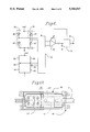
- FIG. 6 is a diagram illustrating the electrical connection of two single axis sensors, or one dual axis sensor, to a circuit capable of producing a digital output signal representative of the degree of flex experienced by the sensors;
- FIG. 7 is a diagrammatic representation of a plurality of single axis and double axis sensors mounted on a glove
- FIGS. 7A, 7B, and 7C are cross-sectional views taken at various positions in FIG. 7 to illustrate the type of sensor used at that location;
- FIG. 8 is an electrical schematic of the sensors of the glove shown in FIG. 7;
- FIG. 9 illustrates a glove having a plurality of single axis and double axis sensors mounted thereon
- FIGS. 10 and 11 illustrate the fixed end of a single axis sensor
- FlGS. 12 and 13 illustrate the fixed end of a double axis sensor
- FlGS. 14 and 15 illustrate the movable ends of a single axis sensor and a double axis sensor.
- the man-machine interface of the present invention is built around a number of sensors of the type illustrated in FIGS. 1-5.
- the sensors illustrated in FIGS. 1-5 are constructed from highly flexible materials capable of flexing in conjunction with the flexing of a human joint.
- the sensors 10, 12, and 14 illustrated in FIGS. 1, 2, and 3, respectively, are each constructed of a highly flexible body 16, 18, and 20, respectively, having a cross section that is symmetric about a longitudinal axis in at least two orthogonal planes.
- the sensor bodies are then processed so that transducers in the form of strain sensing elements are attached along the bodies' longitudinal axis.
- body 16 is provided with strain sensing elements in the form of wires 22, 24, 26, and 28.
- strain sensing elements 22, 24, 26, and 28 may similarly be located around body 18 as shown in FIG. 2.
- strain sensing elements 30, 32, 34, and 36 may be foil strain gauges or piezo-resistive gauges which are typically constructed with thick film, polymer ink having immersed conductive particles such as carbon, copper, or silver acting as a conductive agent.
- the sensors 10, 12, and 14 by virtue of the location of the strain gauges around the sensor's body, are capable of sensing two axis of bending.
- the sensors illustrated in FIGS. 1, 2, and 3 are capable of measuring flex in two directions. That method of construction also results in low sensitivity to bending when the sensors are aligned with the neutral axis of the bending beam.
- the present invention reduces cross-talk that commonly occurs with multiple axis sensors.
- sensor 38 in FIG. 4 and sensor 40 in FIG. 5 is capable of measuring the angle between adjacent bones forming a joint.
- Sensors 38 and 40 are constructed of a highly flexible body of rectangular cross-section. The lessor dimension of the body lies parallel with the bending axis which is the axis in which flex is measured.
- the transducers may again be strain sensing elements such as wires 46 and 48 carried by body 42, or foil or piezo-resistive ink strain gauges 50 and 52 carried by body 44. In that manner, the sensors 38 and 40 illustrated in FIG. 4 and 5 are single axis sensors.
- FIG. 6 an electrical schematic illustrates how single axis sensors, or dual axis sensors, may be connected to a circuit which produces a digital output signal representative of the strain, and hence the degree of flex, experienced by each sensor.
- Each sensor is represented in FIG. 6 by the strain gauges carried by the sensor.
- variable resistors 46 and 48 are representative of the strain gauge transducers 46 and 48 carried by sensor 38 in FIG. 4.
- Resistors 46' and 48' are representative of the transducers carried by a second sensor 38' of the same type as shown in FIG. 4.
- Those of ordinary skill in the art will recognize that any number of sensors, and hence any number of resistor pairs, may be connected between a reference voltage and ground as shown in FIG. 6.
- resistor 56 a resistor 56, a variable resistor 58, and a resistor 60 are connected in series between the reference voltage and ground.
- a second group of series connected resistors 56', 58', and 60' are also connected between the reference voltage and ground.
- a multiplexer 54 connects the sensor resistors 46 and 48 to the series connected resistors 56, 58, 60 so as to provide a balanced bridge. Any unbalance in the bridge is multiplied by an amplifier 57 and input to a microprocessor 59.
- the microprocessor 59 digitizes the analog signal to thereby produce a digital output signal representative of the unbalance of the bridge formed by resistors 46, 48, 56, 58, and 60. Thus, that digital signal is representative of the flex sensed by the sensor 38.
- the processor 59 controls the multiplexer 54 to connect an output signal from a bridge formed of resistors 46', 48', 56', 58', and 60' to amplifier 57. Again, any unbalance is amplified, input to microprocessor 59, and digitized to produce an output signal representative of the flex experienced by sensor 38'.
- the microprocessor 59 continues to control multiplexer 54 until all of the balanced bridges have been checked and the output signals digitized.
- the digitized output signals may be stored within microprocessor 59 or output on a conductor 61.
- FIGS. 1-5 and the circuit illustrated in FIG. 6 may be combined to construct a man-machine interface 62 of the type illustrated in FIG. 7, diagrammatically, and in FIG. 9, which is a top plan view.
- the man-machine interface is constructed of an affixing mechanism, which in FIGS. 7 and 9 takes the form of a partial glove 64, i.e. a glove without finger tips.
- a plurality of single axis sensors 65-69 are carried on partial glove 64 so as to be positioned over the joint between the proximal phalanx bones and the middle phalanx bones.
- FIG. 7A which is a cross-sectional view of sensor 66
- sensors 65-69 may be single axis sensors of the type illustrated in either FIGS. 4 or 5.
- Partial glove 64 carries a plurality of sensors 71-75 which are positioned to span the joint between the metacarpal bones and the proximal phalanx bones. As seen in FIG. 7B, which is a cross-sectional view of sensor 71, sensors 71-75 are dual axis sensors of the type illustrated in any of FIGS. 1-3. Finally, the partial glove 64 carries a sensor 77 positioned to monitor movement of the wrist joint. The sensor 77, shown in cross-section and FIG. 7C, is seen to be of the type illustrated in any of FIGS. 1-3. The sensor 77 may additionally be mounted on a flexible circuit board 79.
- the sensors carried by partial glove 64 may be electrically interconnected as shown in FIG. 8.
- Each of the single axis sensors 65-69 is connected between a reference voltage and ground so that an output signal is available at the junction between the two resistive elements forming the sensor.
- each of the dual axis sensors 71-75 and 77 has each resistor pair within each sensor connected in series between a reference voltage and ground, with an output signal being available at the junction between the two resistor elements. In that manner, a plurality of output signals is available which may be input to a circuit of the type illustrated in FIG. 6.
- the multiplexer 54, amplifier 57, and microprocessor 59 may be carried by flexible circuit board 79.
- Signals produced by the various sensors which are representative of the flexing of the joint which that sensor spans, are digitized right on the glove. Digitizing the signal close to the source of the signal's production, and transmitting a digital rather than an analog signal, increases the accuracy of the system.
- the analog output signals may be input to a circuit of the type illustrated in FIG. 6 housed in a device carried on a belt, or positioned on a tabletop, provided that appropriate electrical connections are provided.
- the preference is to digitize the signals as close to the source of the signals as possible.
- each of the single axis sensors 65-69 has a first fixed end 81 which is rigidly attached to the partial glove 64. All of the fixed ends 81 are identical in construction and operation such that only one need be discussed in detail. That discussion will take place in conjunction with FIGS. 10 and 11.
- Each of the dual axis sensors 71-75 has fixed end 83 which is rigidly connected to the partial glove 64.
- Each of the fixed ends 83 is identical in construction and operation such that only one need be described in detail. That description will take place in conjunction with FIGS. 12 and 13.
- a combination joint 85 provides a sliding attachment for the second end of each of the single axis sensors 65-69 and a sliding attachment for the second end of each of the dual axis sensors 71-75.
- Each of the combination joints 85 is identical in construction and operation such that only one need be described. That description will take place in conjunction with FIGS. 14 and 15.
- the fixed end 81 of the single axis sensors is illustrated in greater detail in FIGS. 10 and 11.
- a tie down button 87 is provided.
- the tie down button 87 has a plurality of apertures by which the tie down button 87 may be rigidly attached to the partial glove 64.
- the tie down button 87 has an enlarged head portion 86 carried by a shaft portion 88.
- the single axis sensor 65 is provided at a first end thereof with a button hole having a large portion 91 sized to fit over the head portion 86.
- the button hole 89 is also provided with a narrow portion 93 so that after the large portion 91 is fitted over tie down button 87, movement of sensor 65 to the right as illustrated in FIG. 10 will cause the narrow portion 93 to engage shaft portion 88.
- the single axis sensor 65 is shown engaging the tie down button 87 in FIG. 11. In that manner, the first end 81 of the sensor 65 is rigidly fixed to the partial glove 64.
- the fixed end 83 of dual axis sensors 71-75 is illustrated in FIGS. 12 and 13.
- the mechanism illustrated in FIGS. 12 and 13 is comprised of a clamp member 95.
- the clamp member 95 has a plurality of apertures by which the clamp member 95 may be rigidly attached to the partial glove 64.
- the clamp member 95 has a groove 97 formed in the upper surface thereof.
- the mechanism shown in FIG. 12 also has a sensor retainer 99.
- the sensor retainer 99 receives and holds a first end of the sensor 71.
- the sensor retainer 99 also receives and retains a flexible, printed circuit board (PCB) wire pad 102. Sensor wires 104 from sensor 71 may be connected to the flexible PCB wire pad 102.
- PCB printed circuit board
- the sensor retainer 99 carries a pair of snaps or tabs 106, shown in phantom in FIG. 12, on the bottom portion thereof.
- the snaps 106 are positioned and sized to fit within groove 97 so as to rigidly hold sensor retainer 99 within clamp 95.
- a top view of sensor retainer 99 snapped into clamp 95 is illustrated in FIG. 13. In that manner, the first end of each of the dual axis sensors is rigidly connected to the partial glove 64.
- a single mechanism 108 provides the sliding connection between the second end of the single axis sensors 65-69 and the second end of the dual axis sensors 71-75 and the partial glove 64.
- the mechanism 108 thus provides the function of the combination joint 85 illustrated in FIG. 9.
- the mechanism 108 is comprised of a clamp/slide member 110.
- the clamp/slide member 110 has a groove 112 formed in the top thereof similar to groove 97 of clamp 95, but of much greater length.
- the clamp/slide member 110 is provided with a plurality of apertures so that it may be rigidly attached to the partial glove 64.
- the clamp/slide member 110 is constructed to have an inverted U-shape thereby forming a tunnel portion 114.
- the mechanism 108 is also comprised of a sensor retainer 116 similar to sensor retainer 99.
- Sensor retainer 116 receives and retains the second end of dual axis sensor 71.
- Sensor retainer 116 need not be configured to retain a flexible printed circuit board as is sensor retainer 99.
- Sensor retainer 116 is provided with snaps or tabs 106 formed in the bottom thereof. Snaps 106 are sized to fit Within groove 112, and because the length of the groove 112 is much larger than the distance between snaps 106, tensile forces acting on sensor 71 may be relieved by movement of sensor retainer 116 relative to clamp/slide member 110. Sensor retainer 116 is thus slidably connected to clamp/slide 110 by virtue of tabs 106. The second end of single axis sensor 65 fits within tunnel 114. Tunnel 114 restricts movement of the second end of the sensor 65 to one direction. Thus, whenever sensor 65 is subjected to tensile forces, those forces may be relieved by second end 65 sliding within tunnel 114.
- the sensor retainer 116 is shown snapped in place in clamp/slide member 110 in FIG. 15. In that manner, the present invention provides a unique mechanism 108 which provides a mechanism for the second end of both the dual axis sensor and the single axis sensor to be slidably connected to the partial glove 64.
- the sensor 77 may be similarly connected such that its first end is rigidly connected to the partial glove 64 while its second end is slidably connected to the partial glove 64. In that manner, tensile forces experienced by wrist sensor 77 may be relieved.
- the partial glove 64 is provided with an output port 118.
- the type of signal available at output port 118 will depend upon the electronics carried by partial glove 64. In the event that partial glove 64 carries a multiplexer, processor, and analog to digital converter, then the signals available at output port 118 will be digital signals representative of the degree of flex experienced by each of sensors. If such electronics are not carried by partial glove 64, then the signals available at output port 118 will be analog signals representative of the degree of flex experienced by each of the sensors. Those analog signals may be input to an interface device containing the type of electronics previously described above in conjunction with the glove. The signals available at output port 118 may be input to any computer running, for example, commercial instrumentation software.
- the man-machine interface of the present invention thus represents a substantial advance over the art.
- the accuracy found in exoskeletal systems is reproduced in a glove-based system by allowing tensile forces experience by the sensors to be relieved.
- the signals produced by the sensors more accurately represent the degree of flex experienced by the sensor.
- the convenience of affixing the man-machine interface to a patient is retained. Further, by digitizing the signals closer to their source, accuracy is enhanced.
- the affixing mechanism need not be a glove.
- the affixing mechanism may take other shapes or may simply be strips of material provided with Velcro which may be wrapped around a joint, for example, an ankle or elbow joint.
- the electronics carried by the glove could be carried in a separate component clipped on a belt or otherwise conveniently located close to the glove.
Abstract
Description
Claims (14)
Priority Applications (1)
| Application Number | Priority Date | Filing Date | Title |
|---|---|---|---|
| US07/957,716 US5316017A (en) | 1992-10-07 | 1992-10-07 | Man-machine interface for a joint measurement system |
Applications Claiming Priority (1)
| Application Number | Priority Date | Filing Date | Title |
|---|---|---|---|
| US07/957,716 US5316017A (en) | 1992-10-07 | 1992-10-07 | Man-machine interface for a joint measurement system |
Publications (1)
| Publication Number | Publication Date |
|---|---|
| US5316017A true US5316017A (en) | 1994-05-31 |
Family
ID=25500020
Family Applications (1)
| Application Number | Title | Priority Date | Filing Date |
|---|---|---|---|
| US07/957,716 Expired - Lifetime US5316017A (en) | 1992-10-07 | 1992-10-07 | Man-machine interface for a joint measurement system |
Country Status (1)
| Country | Link |
|---|---|
| US (1) | US5316017A (en) |
Cited By (74)
| Publication number | Priority date | Publication date | Assignee | Title |
|---|---|---|---|---|
| US5482056A (en) * | 1994-04-04 | 1996-01-09 | Kramer; James F. | Determination of thumb position using measurements of abduction and rotation |
| US5533531A (en) * | 1994-08-22 | 1996-07-09 | Greenleaf Medical Systems | Electronically aligned man-machine interface |
| US5586943A (en) * | 1993-10-08 | 1996-12-24 | Clay; Hailie S. | Golf training device |
| US5785666A (en) * | 1995-10-31 | 1998-07-28 | Ergonomic Technologies Corporation | Portable electronic data collection apparatus for monitoring musculoskeletal stresses |
| WO1998050839A2 (en) * | 1997-04-23 | 1998-11-12 | Modern Cartoons, Ltd. | System for data management based on hand gestures |
| WO1999021478A1 (en) * | 1997-10-24 | 1999-05-06 | Virtual Technologies, Inc. | An exoskeleton device for directly measuring fingertip position and inferring finger joint angle |
| US6050962A (en) * | 1997-04-21 | 2000-04-18 | Virtual Technologies, Inc. | Goniometer-based body-tracking device and method |
| US6127672A (en) * | 1997-05-23 | 2000-10-03 | Canadian Space Agency | Topological and motion measuring tool |
| US6325768B1 (en) * | 1996-05-18 | 2001-12-04 | The University Of Sheffield | Glove for making goniometric measures |
| US6334852B1 (en) * | 1998-02-20 | 2002-01-01 | Motionwatch L.L.C. | Joint movement monitoring system |
| US6413229B1 (en) | 1997-05-12 | 2002-07-02 | Virtual Technologies, Inc | Force-feedback interface device for the hand |
| US6487906B1 (en) * | 2000-09-18 | 2002-12-03 | Advantedge Systems Inc | Flexible film sensor system for monitoring body motion |
| US6491649B1 (en) | 2000-10-06 | 2002-12-10 | Mark P. Ombrellaro | Device for the direct manual examination of a patient in a non-contiguous location |
| US6554252B2 (en) | 2001-09-28 | 2003-04-29 | Homayoon Kazerooni | Device and method for wireless lifting assist devices |
| US6573883B1 (en) * | 1998-06-24 | 2003-06-03 | Hewlett Packard Development Company, L.P. | Method and apparatus for controlling a computing device with gestures |
| US6622575B1 (en) * | 1999-07-07 | 2003-09-23 | Agency Of Industrial Science And Technology | Fingertip-mounted six-axis force sensor |
| US20030181832A1 (en) * | 2002-03-22 | 2003-09-25 | Carnahan James V. | Augmented kinematic feedback device and method |
| US6651352B2 (en) * | 2002-01-04 | 2003-11-25 | Liberty Mutual | Wrist motion measurement device |
| US6681638B2 (en) | 2001-05-04 | 2004-01-27 | Homayoon Kazerooni | Device and method for wireless material handling systems |
| US20040097836A1 (en) * | 2000-10-06 | 2004-05-20 | Ombrellaro Mark P. | Direct manual examination of remote patient with virtual examination functionality |
| US20050017947A1 (en) * | 2000-01-19 | 2005-01-27 | Shahoian Erik J. | Haptic input devices |
| US20050149364A1 (en) * | 2000-10-06 | 2005-07-07 | Ombrellaro Mark P. | Multifunction telemedicine software with integrated electronic medical record |
| US20050178213A1 (en) * | 2004-02-13 | 2005-08-18 | Jason Skowronski | Device for determining finger rotation using a displacement sensor |
| US20050233707A1 (en) * | 2004-04-16 | 2005-10-20 | Hon Hai Precision Industry Co., Ltd | Mobile phone with health care functionality |
| US20060109256A1 (en) * | 2004-10-08 | 2006-05-25 | Immersion Corporation, A Delaware Corporation | Haptic feedback for button and scrolling action simulation in touch input devices |
| US20060119589A1 (en) * | 1998-06-23 | 2006-06-08 | Immersion Corporation | Haptic feedback for touchpads and other touch controls |
| US20060129070A1 (en) * | 2004-11-05 | 2006-06-15 | Pearl Michael L | Fingertip tracker |
| US20060256075A1 (en) * | 2005-05-12 | 2006-11-16 | Immersion Corporation | Method and apparatus for providing haptic effects to a touch panel |
| US20070116415A1 (en) * | 2005-11-24 | 2007-05-24 | Pentax Corporation | Configuration detection device for endoscope |
| US20070283737A1 (en) * | 2006-05-31 | 2007-12-13 | Suehiro Mizukawa | Method and apparatus for bending a blade member |
| US7336266B2 (en) | 2003-02-20 | 2008-02-26 | Immersion Corproation | Haptic pads for use with user-interface devices |
| US20080091373A1 (en) * | 2006-07-31 | 2008-04-17 | University Of New Brunswick | Method for calibrating sensor positions in a human movement measurement and analysis system |
| US20080161731A1 (en) * | 2006-12-27 | 2008-07-03 | Woods Sherrod A | Apparatus, system, and method for monitoring the range of motion of a patient's joint |
| WO2009010518A1 (en) * | 2007-07-18 | 2009-01-22 | Siemens Aktiengesellschaft | Support structure for a sensor strip and sensor strip for mounting on said support structure |
| US20100081969A1 (en) * | 2008-09-30 | 2010-04-01 | Gm Global Technology Operations, Inc. | Tendon tension sensor |
| US8059088B2 (en) | 2002-12-08 | 2011-11-15 | Immersion Corporation | Methods and systems for providing haptic messaging to handheld communication devices |
| US8316166B2 (en) | 2002-12-08 | 2012-11-20 | Immersion Corporation | Haptic messaging in handheld communication devices |
| CN103268156A (en) * | 2013-05-24 | 2013-08-28 | 徐州医学院 | Wrist-strap-type gesture recognition device based on human-computer interaction |
| WO2013149181A1 (en) * | 2012-03-30 | 2013-10-03 | The Board Of Trustees Of The University Of Illinois | Appendage mountable electronic devices conformable to surfaces |
| CN103692454A (en) * | 2013-12-12 | 2014-04-02 | 浙江理工大学 | Exoskeleton wearable data glove |
| US8830161B2 (en) | 2002-12-08 | 2014-09-09 | Immersion Corporation | Methods and systems for providing a virtual touch haptic effect to handheld communication devices |
| US9012784B2 (en) | 2008-10-07 | 2015-04-21 | Mc10, Inc. | Extremely stretchable electronics |
| US20150190246A1 (en) * | 2012-08-02 | 2015-07-09 | Korea University Of Technology And Education Industry-University Cooperation Foundation | Motion control device based on winding string |
| CN104924308A (en) * | 2014-03-20 | 2015-09-23 | 赵德朝 | Exoskeleton data glove for sensing hand movements |
| US20160070347A1 (en) * | 2014-06-09 | 2016-03-10 | Bebop Sensors, Inc. | Sensor system integrated with a glove |
| US9582072B2 (en) | 2013-09-17 | 2017-02-28 | Medibotics Llc | Motion recognition clothing [TM] with flexible electromagnetic, light, or sonic energy pathways |
| US20170215495A1 (en) * | 2014-10-17 | 2017-08-03 | Yamaha Corporation | Data Glove |
| US9753568B2 (en) | 2014-05-15 | 2017-09-05 | Bebop Sensors, Inc. | Flexible sensors and applications |
| US9827996B2 (en) | 2015-06-25 | 2017-11-28 | Bebop Sensors, Inc. | Sensor systems integrated with steering wheels |
| US9836151B2 (en) | 2012-03-14 | 2017-12-05 | Bebop Sensors, Inc. | Multi-touch pad controller |
| US9863823B2 (en) | 2015-02-27 | 2018-01-09 | Bebop Sensors, Inc. | Sensor systems integrated with footwear |
| US9891718B2 (en) | 2015-04-22 | 2018-02-13 | Medibotics Llc | Devices for measuring finger motion and recognizing hand gestures |
| CN107704087A (en) * | 2017-10-26 | 2018-02-16 | 哈尔滨工业大学 | Data glove scaling method based on joint correlation analysis |
| US9965076B2 (en) | 2014-05-15 | 2018-05-08 | Bebop Sensors, Inc. | Piezoresistive sensors and applications |
| US10082381B2 (en) | 2015-04-30 | 2018-09-25 | Bebop Sensors, Inc. | Sensor systems integrated with vehicle tires |
| TWI642421B (en) * | 2018-01-05 | 2018-12-01 | 富伯生醫科技股份有限公司 | Finger motion sensing gloves capable of fixing sensors |
| US10234934B2 (en) | 2013-09-17 | 2019-03-19 | Medibotics Llc | Sensor array spanning multiple radial quadrants to measure body joint movement |
| US10268315B2 (en) | 2014-05-15 | 2019-04-23 | Bebop Sensors, Inc. | Two-dimensional sensor arrays |
| US10288507B2 (en) | 2009-10-16 | 2019-05-14 | Bebop Sensors, Inc. | Piezoresistive sensors and sensor arrays |
| US10321873B2 (en) | 2013-09-17 | 2019-06-18 | Medibotics Llc | Smart clothing for ambulatory human motion capture |
| US10362989B2 (en) | 2014-06-09 | 2019-07-30 | Bebop Sensors, Inc. | Sensor system integrated with a glove |
| DE102018203193A1 (en) * | 2018-03-02 | 2019-09-05 | Fraunhofer-Gesellschaft zur Förderung der angewandten Forschung e.V. | Flexible handheld portable control for controlling an electrically controllable device and uses thereof |
| US10441185B2 (en) | 2009-12-16 | 2019-10-15 | The Board Of Trustees Of The University Of Illinois | Flexible and stretchable electronic systems for epidermal electronics |
| CN110764607A (en) * | 2018-07-26 | 2020-02-07 | 宏碁股份有限公司 | Gesture sensing system using bionic ligament |
| US10599217B1 (en) * | 2016-09-26 | 2020-03-24 | Facebook Technologies, Llc | Kinematic model for hand position |
| US10602965B2 (en) | 2013-09-17 | 2020-03-31 | Medibotics | Wearable deformable conductive sensors for human motion capture including trans-joint pitch, yaw, and roll |
| US10716510B2 (en) | 2013-09-17 | 2020-07-21 | Medibotics | Smart clothing with converging/diverging bend or stretch sensors for measuring body motion or configuration |
| US10820862B2 (en) | 2013-10-02 | 2020-11-03 | The Board Of Trustees Of The University Of Illinois | Organ mounted electronics |
| US10884496B2 (en) | 2018-07-05 | 2021-01-05 | Bebop Sensors, Inc. | One-size-fits-all data glove |
| US10895914B2 (en) | 2010-10-22 | 2021-01-19 | Joshua Michael Young | Methods, devices, and methods for creating control signals |
| US11029757B1 (en) | 2015-09-24 | 2021-06-08 | Facebook Technologies, Llc | Detecting positions of magnetic flux sensors having particular locations on a device relative to a magnetic field generator located at a predetermined position on the device |
| US11029198B2 (en) | 2015-06-01 | 2021-06-08 | The Board Of Trustees Of The University Of Illinois | Alternative approach for UV sensing |
| US11118965B2 (en) | 2015-06-01 | 2021-09-14 | The Board Of Trustees Of The University Of Illinois | Miniaturized electronic systems with wireless power and near-field communication capabilities |
| US11480481B2 (en) | 2019-03-13 | 2022-10-25 | Bebop Sensors, Inc. | Alignment mechanisms sensor systems employing piezoresistive materials |
Citations (10)
| Publication number | Priority date | Publication date | Assignee | Title |
|---|---|---|---|---|
| US4414537A (en) * | 1981-09-15 | 1983-11-08 | Bell Telephone Laboratories, Incorporated | Digital data entry glove interface device |
| US4444205A (en) * | 1980-05-31 | 1984-04-24 | University Of Strathclyde | Apparatus for assessing joint mobility |
| US4542291A (en) * | 1982-09-29 | 1985-09-17 | Vpl Research Inc. | Optical flex sensor |
| JPS60219501A (en) * | 1984-04-16 | 1985-11-02 | Kazuo Tsuchiya | Detection gauge for detecting deformation amount of living body |
| WO1986001588A1 (en) * | 1984-09-01 | 1986-03-13 | University Of Strathclyde | Electrical angular displacement sensor |
| US4715235A (en) * | 1985-03-04 | 1987-12-29 | Asahi Kasei Kogyo Kabushiki Kaisha | Deformation sensitive electroconductive knitted or woven fabric and deformation sensitive electroconductive device comprising the same |
| US4986280A (en) * | 1988-07-20 | 1991-01-22 | Arthur D. Little, Inc. | Hand position/measurement control system |
| US5047952A (en) * | 1988-10-14 | 1991-09-10 | The Board Of Trustee Of The Leland Stanford Junior University | Communication system for deaf, deaf-blind, or non-vocal individuals using instrumented glove |
| US5086785A (en) * | 1989-08-10 | 1992-02-11 | Abrams/Gentille Entertainment Inc. | Angular displacement sensors |
| US5166462A (en) * | 1989-03-17 | 1992-11-24 | Yamaha Corporation | Musical tone control apparatus employing finger flexing angle detection |
-
1992
- 1992-10-07 US US07/957,716 patent/US5316017A/en not_active Expired - Lifetime
Patent Citations (11)
| Publication number | Priority date | Publication date | Assignee | Title |
|---|---|---|---|---|
| US4444205A (en) * | 1980-05-31 | 1984-04-24 | University Of Strathclyde | Apparatus for assessing joint mobility |
| EP0115620A2 (en) * | 1980-05-31 | 1984-08-15 | University of Strathclyde | Method and apparatus for assessing joint mobility |
| US4414537A (en) * | 1981-09-15 | 1983-11-08 | Bell Telephone Laboratories, Incorporated | Digital data entry glove interface device |
| US4542291A (en) * | 1982-09-29 | 1985-09-17 | Vpl Research Inc. | Optical flex sensor |
| JPS60219501A (en) * | 1984-04-16 | 1985-11-02 | Kazuo Tsuchiya | Detection gauge for detecting deformation amount of living body |
| WO1986001588A1 (en) * | 1984-09-01 | 1986-03-13 | University Of Strathclyde | Electrical angular displacement sensor |
| US4715235A (en) * | 1985-03-04 | 1987-12-29 | Asahi Kasei Kogyo Kabushiki Kaisha | Deformation sensitive electroconductive knitted or woven fabric and deformation sensitive electroconductive device comprising the same |
| US4986280A (en) * | 1988-07-20 | 1991-01-22 | Arthur D. Little, Inc. | Hand position/measurement control system |
| US5047952A (en) * | 1988-10-14 | 1991-09-10 | The Board Of Trustee Of The Leland Stanford Junior University | Communication system for deaf, deaf-blind, or non-vocal individuals using instrumented glove |
| US5166462A (en) * | 1989-03-17 | 1992-11-24 | Yamaha Corporation | Musical tone control apparatus employing finger flexing angle detection |
| US5086785A (en) * | 1989-08-10 | 1992-02-11 | Abrams/Gentille Entertainment Inc. | Angular displacement sensors |
Cited By (144)
| Publication number | Priority date | Publication date | Assignee | Title |
|---|---|---|---|---|
| US5586943A (en) * | 1993-10-08 | 1996-12-24 | Clay; Hailie S. | Golf training device |
| US5482056A (en) * | 1994-04-04 | 1996-01-09 | Kramer; James F. | Determination of thumb position using measurements of abduction and rotation |
| US5533531A (en) * | 1994-08-22 | 1996-07-09 | Greenleaf Medical Systems | Electronically aligned man-machine interface |
| US5785666A (en) * | 1995-10-31 | 1998-07-28 | Ergonomic Technologies Corporation | Portable electronic data collection apparatus for monitoring musculoskeletal stresses |
| US5964719A (en) * | 1995-10-31 | 1999-10-12 | Ergonomic Technologies Corp. | Portable electronic data collection apparatus for monitoring musculoskeletal stresses |
| US6325768B1 (en) * | 1996-05-18 | 2001-12-04 | The University Of Sheffield | Glove for making goniometric measures |
| US6110130A (en) * | 1997-04-21 | 2000-08-29 | Virtual Technologies, Inc. | Exoskeleton device for directly measuring fingertip position and inferring finger joint angle |
| US7070571B2 (en) | 1997-04-21 | 2006-07-04 | Immersion Corporation | Goniometer-based body-tracking device |
| US6428490B1 (en) | 1997-04-21 | 2002-08-06 | Virtual Technologies, Inc. | Goniometer-based body-tracking device and method |
| US6050962A (en) * | 1997-04-21 | 2000-04-18 | Virtual Technologies, Inc. | Goniometer-based body-tracking device and method |
| WO1998050839A3 (en) * | 1997-04-23 | 1999-03-18 | Modern Cartoons Ltd | System for data management based on hand gestures |
| US6049327A (en) * | 1997-04-23 | 2000-04-11 | Modern Cartoons, Ltd | System for data management based onhand gestures |
| US6452584B1 (en) | 1997-04-23 | 2002-09-17 | Modern Cartoon, Ltd. | System for data management based on hand gestures |
| WO1998050839A2 (en) * | 1997-04-23 | 1998-11-12 | Modern Cartoons, Ltd. | System for data management based on hand gestures |
| US6413229B1 (en) | 1997-05-12 | 2002-07-02 | Virtual Technologies, Inc | Force-feedback interface device for the hand |
| US6127672A (en) * | 1997-05-23 | 2000-10-03 | Canadian Space Agency | Topological and motion measuring tool |
| EP1030596A1 (en) * | 1997-10-24 | 2000-08-30 | Virtual Technologies, Inc. | An exoskeleton device for directly measuring fingertip position and inferring finger joint angle |
| WO1999021478A1 (en) * | 1997-10-24 | 1999-05-06 | Virtual Technologies, Inc. | An exoskeleton device for directly measuring fingertip position and inferring finger joint angle |
| EP1030596A4 (en) * | 1997-10-24 | 2004-08-18 | Immersion Corp | An exoskeleton device for directly measuring fingertip position and inferring finger joint angle |
| US6497672B2 (en) | 1997-10-24 | 2002-12-24 | Virtual Technologies, Inc. | Device and method for measuring the position of animate links |
| US6334852B1 (en) * | 1998-02-20 | 2002-01-01 | Motionwatch L.L.C. | Joint movement monitoring system |
| US8049734B2 (en) | 1998-06-23 | 2011-11-01 | Immersion Corporation | Haptic feedback for touchpads and other touch control |
| US20070229483A1 (en) * | 1998-06-23 | 2007-10-04 | Immersion Corporation | Haptic feedback for touchpads and other touch controls |
| US7592999B2 (en) | 1998-06-23 | 2009-09-22 | Immersion Corporation | Haptic feedback for touchpads and other touch controls |
| US7728820B2 (en) | 1998-06-23 | 2010-06-01 | Immersion Corporation | Haptic feedback for touchpads and other touch controls |
| US7768504B2 (en) | 1998-06-23 | 2010-08-03 | Immersion Corporation | Haptic feedback for touchpads and other touch controls |
| US7777716B2 (en) | 1998-06-23 | 2010-08-17 | Immersion Corporation | Haptic feedback for touchpads and other touch controls |
| US7944435B2 (en) | 1998-06-23 | 2011-05-17 | Immersion Corporation | Haptic feedback for touchpads and other touch controls |
| US7978183B2 (en) | 1998-06-23 | 2011-07-12 | Immersion Corporation | Haptic feedback for touchpads and other touch controls |
| US7982720B2 (en) | 1998-06-23 | 2011-07-19 | Immersion Corporation | Haptic feedback for touchpads and other touch controls |
| US20070229478A1 (en) * | 1998-06-23 | 2007-10-04 | Immersion Corporation | Haptic feedback for touchpads and other touch controls |
| US8031181B2 (en) | 1998-06-23 | 2011-10-04 | Immersion Corporation | Haptic feedback for touchpads and other touch controls |
| US20070013677A1 (en) * | 1998-06-23 | 2007-01-18 | Immersion Corporation | Haptic feedback for touchpads and other touch controls |
| US7602384B2 (en) | 1998-06-23 | 2009-10-13 | Immersion Corporation | Haptic feedback touchpad |
| US20060192771A1 (en) * | 1998-06-23 | 2006-08-31 | Immersion Corporation | Haptic feedback touchpad |
| US8059105B2 (en) | 1998-06-23 | 2011-11-15 | Immersion Corporation | Haptic feedback for touchpads and other touch controls |
| US8063893B2 (en) | 1998-06-23 | 2011-11-22 | Immersion Corporation | Haptic feedback for touchpads and other touch controls |
| US20060119589A1 (en) * | 1998-06-23 | 2006-06-08 | Immersion Corporation | Haptic feedback for touchpads and other touch controls |
| US6573883B1 (en) * | 1998-06-24 | 2003-06-03 | Hewlett Packard Development Company, L.P. | Method and apparatus for controlling a computing device with gestures |
| US6622575B1 (en) * | 1999-07-07 | 2003-09-23 | Agency Of Industrial Science And Technology | Fingertip-mounted six-axis force sensor |
| US9280205B2 (en) | 1999-12-17 | 2016-03-08 | Immersion Corporation | Haptic feedback for touchpads and other touch controls |
| US8188981B2 (en) | 2000-01-19 | 2012-05-29 | Immersion Corporation | Haptic interface for touch screen embodiments |
| US7450110B2 (en) | 2000-01-19 | 2008-11-11 | Immersion Corporation | Haptic input devices |
| US8059104B2 (en) | 2000-01-19 | 2011-11-15 | Immersion Corporation | Haptic interface for touch screen embodiments |
| US20050052430A1 (en) * | 2000-01-19 | 2005-03-10 | Shahoian Erik J. | Haptic interface for laptop computers and other portable devices |
| US20050017947A1 (en) * | 2000-01-19 | 2005-01-27 | Shahoian Erik J. | Haptic input devices |
| US8063892B2 (en) | 2000-01-19 | 2011-11-22 | Immersion Corporation | Haptic interface for touch screen embodiments |
| US7548232B2 (en) | 2000-01-19 | 2009-06-16 | Immersion Corporation | Haptic interface for laptop computers and other portable devices |
| US20080062143A1 (en) * | 2000-01-19 | 2008-03-13 | Immersion Corporation | Haptic interface for touch screen embodiments |
| US6487906B1 (en) * | 2000-09-18 | 2002-12-03 | Advantedge Systems Inc | Flexible film sensor system for monitoring body motion |
| US20040097836A1 (en) * | 2000-10-06 | 2004-05-20 | Ombrellaro Mark P. | Direct manual examination of remote patient with virtual examination functionality |
| US6726638B2 (en) | 2000-10-06 | 2004-04-27 | Cel-Kom Llc | Direct manual examination of remote patient with virtual examination functionality |
| US6491649B1 (en) | 2000-10-06 | 2002-12-10 | Mark P. Ombrellaro | Device for the direct manual examination of a patient in a non-contiguous location |
| US20050149364A1 (en) * | 2000-10-06 | 2005-07-07 | Ombrellaro Mark P. | Multifunction telemedicine software with integrated electronic medical record |
| US6681638B2 (en) | 2001-05-04 | 2004-01-27 | Homayoon Kazerooni | Device and method for wireless material handling systems |
| US6554252B2 (en) | 2001-09-28 | 2003-04-29 | Homayoon Kazerooni | Device and method for wireless lifting assist devices |
| US6651352B2 (en) * | 2002-01-04 | 2003-11-25 | Liberty Mutual | Wrist motion measurement device |
| US7033281B2 (en) | 2002-03-22 | 2006-04-25 | Carnahan James V | Augmented kinematic feedback device and method |
| US20030181832A1 (en) * | 2002-03-22 | 2003-09-25 | Carnahan James V. | Augmented kinematic feedback device and method |
| US8803795B2 (en) | 2002-12-08 | 2014-08-12 | Immersion Corporation | Haptic communication devices |
| US8830161B2 (en) | 2002-12-08 | 2014-09-09 | Immersion Corporation | Methods and systems for providing a virtual touch haptic effect to handheld communication devices |
| US8316166B2 (en) | 2002-12-08 | 2012-11-20 | Immersion Corporation | Haptic messaging in handheld communication devices |
| US8059088B2 (en) | 2002-12-08 | 2011-11-15 | Immersion Corporation | Methods and systems for providing haptic messaging to handheld communication devices |
| US7336266B2 (en) | 2003-02-20 | 2008-02-26 | Immersion Corproation | Haptic pads for use with user-interface devices |
| US20050178213A1 (en) * | 2004-02-13 | 2005-08-18 | Jason Skowronski | Device for determining finger rotation using a displacement sensor |
| US20050233707A1 (en) * | 2004-04-16 | 2005-10-20 | Hon Hai Precision Industry Co., Ltd | Mobile phone with health care functionality |
| US8264465B2 (en) | 2004-10-08 | 2012-09-11 | Immersion Corporation | Haptic feedback for button and scrolling action simulation in touch input devices |
| US8232969B2 (en) | 2004-10-08 | 2012-07-31 | Immersion Corporation | Haptic feedback for button and scrolling action simulation in touch input devices |
| US20060109256A1 (en) * | 2004-10-08 | 2006-05-25 | Immersion Corporation, A Delaware Corporation | Haptic feedback for button and scrolling action simulation in touch input devices |
| US20060119586A1 (en) * | 2004-10-08 | 2006-06-08 | Immersion Corporation, A Delaware Corporation | Haptic feedback for button and scrolling action simulation in touch input devices |
| US7662113B2 (en) | 2004-11-05 | 2010-02-16 | California Institute Of Technology | Fingertip tracker |
| US20060129070A1 (en) * | 2004-11-05 | 2006-06-15 | Pearl Michael L | Fingertip tracker |
| US7825903B2 (en) | 2005-05-12 | 2010-11-02 | Immersion Corporation | Method and apparatus for providing haptic effects to a touch panel |
| US20060256075A1 (en) * | 2005-05-12 | 2006-11-16 | Immersion Corporation | Method and apparatus for providing haptic effects to a touch panel |
| US20110043474A1 (en) * | 2005-05-12 | 2011-02-24 | Immersion Corporation | Method And Apparatus For Providing Haptic Effects To A Touch Panel |
| US8502792B2 (en) | 2005-05-12 | 2013-08-06 | Immersion Corporation | Method and apparatus for providing haptic effects to a touch panel using magnetic devices |
| US20070116415A1 (en) * | 2005-11-24 | 2007-05-24 | Pentax Corporation | Configuration detection device for endoscope |
| US7440661B2 (en) * | 2005-11-24 | 2008-10-21 | Hoya Corporation | Configuration detection device for endoscope |
| US20070283737A1 (en) * | 2006-05-31 | 2007-12-13 | Suehiro Mizukawa | Method and apparatus for bending a blade member |
| US20080091373A1 (en) * | 2006-07-31 | 2008-04-17 | University Of New Brunswick | Method for calibrating sensor positions in a human movement measurement and analysis system |
| US20080161731A1 (en) * | 2006-12-27 | 2008-07-03 | Woods Sherrod A | Apparatus, system, and method for monitoring the range of motion of a patient's joint |
| US20100240981A1 (en) * | 2007-07-18 | 2010-09-23 | Grigorios Barboutis | Support structure for a sensor strip and sensor strip for mounting on said support structure |
| US8435191B2 (en) | 2007-07-18 | 2013-05-07 | Siemens Aktiengesellschaft | Support structure for a sensor strip and sensor strip for mounting on said support structure |
| WO2009010518A1 (en) * | 2007-07-18 | 2009-01-22 | Siemens Aktiengesellschaft | Support structure for a sensor strip and sensor strip for mounting on said support structure |
| US8371177B2 (en) * | 2008-09-30 | 2013-02-12 | GM Global Technology Operations LLC | Tendon tension sensor |
| DE102009042979B4 (en) * | 2008-09-30 | 2017-06-29 | GM Global Technology Operations LLC (n. d. Ges. d. Staates Delaware) | Tendon tension sensor |
| US20100081969A1 (en) * | 2008-09-30 | 2010-04-01 | Gm Global Technology Operations, Inc. | Tendon tension sensor |
| US9012784B2 (en) | 2008-10-07 | 2015-04-21 | Mc10, Inc. | Extremely stretchable electronics |
| US10753814B2 (en) | 2009-10-16 | 2020-08-25 | Bebop Sensors, Inc. | Piezoresistive sensors and sensor arrays |
| US10288507B2 (en) | 2009-10-16 | 2019-05-14 | Bebop Sensors, Inc. | Piezoresistive sensors and sensor arrays |
| US10441185B2 (en) | 2009-12-16 | 2019-10-15 | The Board Of Trustees Of The University Of Illinois | Flexible and stretchable electronic systems for epidermal electronics |
| US10895914B2 (en) | 2010-10-22 | 2021-01-19 | Joshua Michael Young | Methods, devices, and methods for creating control signals |
| US10802641B2 (en) | 2012-03-14 | 2020-10-13 | Bebop Sensors, Inc. | Piezoresistive sensors and applications |
| US10114493B2 (en) | 2012-03-14 | 2018-10-30 | Bebop Sensors, Inc. | Multi-touch pad controller |
| US9836151B2 (en) | 2012-03-14 | 2017-12-05 | Bebop Sensors, Inc. | Multi-touch pad controller |
| US11204664B2 (en) | 2012-03-14 | 2021-12-21 | Bebop Sensors, Inc | Piezoresistive sensors and applications |
| US9554484B2 (en) | 2012-03-30 | 2017-01-24 | The Board Of Trustees Of The University Of Illinois | Appendage mountable electronic devices conformable to surfaces |
| WO2013149181A1 (en) * | 2012-03-30 | 2013-10-03 | The Board Of Trustees Of The University Of Illinois | Appendage mountable electronic devices conformable to surfaces |
| US10357201B2 (en) | 2012-03-30 | 2019-07-23 | The Board Of Trustees Of The University Of Illinois | Appendage mountable electronic devices conformable to surfaces |
| CN105283122A (en) * | 2012-03-30 | 2016-01-27 | 伊利诺伊大学评议会 | Appendage mountable electronic devices conformable to surfaces |
| US10052066B2 (en) | 2012-03-30 | 2018-08-21 | The Board Of Trustees Of The University Of Illinois | Appendage mountable electronic devices conformable to surfaces |
| US20150190246A1 (en) * | 2012-08-02 | 2015-07-09 | Korea University Of Technology And Education Industry-University Cooperation Foundation | Motion control device based on winding string |
| US9566173B2 (en) * | 2012-08-02 | 2017-02-14 | Korea University Of Technology And Education Industry-University Cooperation Foundation | Motion control device based on winding string |
| CN103268156A (en) * | 2013-05-24 | 2013-08-28 | 徐州医学院 | Wrist-strap-type gesture recognition device based on human-computer interaction |
| CN103268156B (en) * | 2013-05-24 | 2015-12-23 | 徐州医学院 | A kind of Wrist-strap-type gesture recognition device based on man-machine interaction |
| US9582072B2 (en) | 2013-09-17 | 2017-02-28 | Medibotics Llc | Motion recognition clothing [TM] with flexible electromagnetic, light, or sonic energy pathways |
| US10321873B2 (en) | 2013-09-17 | 2019-06-18 | Medibotics Llc | Smart clothing for ambulatory human motion capture |
| US10716510B2 (en) | 2013-09-17 | 2020-07-21 | Medibotics | Smart clothing with converging/diverging bend or stretch sensors for measuring body motion or configuration |
| US10602965B2 (en) | 2013-09-17 | 2020-03-31 | Medibotics | Wearable deformable conductive sensors for human motion capture including trans-joint pitch, yaw, and roll |
| US10234934B2 (en) | 2013-09-17 | 2019-03-19 | Medibotics Llc | Sensor array spanning multiple radial quadrants to measure body joint movement |
| US10820862B2 (en) | 2013-10-02 | 2020-11-03 | The Board Of Trustees Of The University Of Illinois | Organ mounted electronics |
| CN103692454A (en) * | 2013-12-12 | 2014-04-02 | 浙江理工大学 | Exoskeleton wearable data glove |
| CN103692454B (en) * | 2013-12-12 | 2015-10-28 | 浙江理工大学 | Exoskeleton wearable data glove |
| CN104924308A (en) * | 2014-03-20 | 2015-09-23 | 赵德朝 | Exoskeleton data glove for sensing hand movements |
| CN104924308B (en) * | 2014-03-20 | 2016-07-06 | 赵德朝 | A kind of external frame type data glove detecting hand motion |
| US10268315B2 (en) | 2014-05-15 | 2019-04-23 | Bebop Sensors, Inc. | Two-dimensional sensor arrays |
| US10282011B2 (en) | 2014-05-15 | 2019-05-07 | Bebop Sensors, Inc. | Flexible sensors and applications |
| US9753568B2 (en) | 2014-05-15 | 2017-09-05 | Bebop Sensors, Inc. | Flexible sensors and applications |
| US9965076B2 (en) | 2014-05-15 | 2018-05-08 | Bebop Sensors, Inc. | Piezoresistive sensors and applications |
| US11147510B2 (en) | 2014-06-09 | 2021-10-19 | Bebop Sensors, Inc. | Flexible sensors and sensor systems |
| US20160070347A1 (en) * | 2014-06-09 | 2016-03-10 | Bebop Sensors, Inc. | Sensor system integrated with a glove |
| US9710060B2 (en) * | 2014-06-09 | 2017-07-18 | BeBop Senors, Inc. | Sensor system integrated with a glove |
| US10362989B2 (en) | 2014-06-09 | 2019-07-30 | Bebop Sensors, Inc. | Sensor system integrated with a glove |
| US10455874B2 (en) * | 2014-10-17 | 2019-10-29 | Yamaha Corporation | Data glove |
| US20170215495A1 (en) * | 2014-10-17 | 2017-08-03 | Yamaha Corporation | Data Glove |
| US10352787B2 (en) | 2015-02-27 | 2019-07-16 | Bebop Sensors, Inc. | Sensor systems integrated with footwear |
| US9863823B2 (en) | 2015-02-27 | 2018-01-09 | Bebop Sensors, Inc. | Sensor systems integrated with footwear |
| US9891718B2 (en) | 2015-04-22 | 2018-02-13 | Medibotics Llc | Devices for measuring finger motion and recognizing hand gestures |
| US10082381B2 (en) | 2015-04-30 | 2018-09-25 | Bebop Sensors, Inc. | Sensor systems integrated with vehicle tires |
| US11118965B2 (en) | 2015-06-01 | 2021-09-14 | The Board Of Trustees Of The University Of Illinois | Miniaturized electronic systems with wireless power and near-field communication capabilities |
| US11029198B2 (en) | 2015-06-01 | 2021-06-08 | The Board Of Trustees Of The University Of Illinois | Alternative approach for UV sensing |
| US10654486B2 (en) | 2015-06-25 | 2020-05-19 | Bebop Sensors, Inc. | Sensor systems integrated with steering wheels |
| US9827996B2 (en) | 2015-06-25 | 2017-11-28 | Bebop Sensors, Inc. | Sensor systems integrated with steering wheels |
| US11029757B1 (en) | 2015-09-24 | 2021-06-08 | Facebook Technologies, Llc | Detecting positions of magnetic flux sensors having particular locations on a device relative to a magnetic field generator located at a predetermined position on the device |
| US10831272B1 (en) | 2016-09-26 | 2020-11-10 | Facebook Technologies, Llc | Kinematic model for hand position |
| US10599217B1 (en) * | 2016-09-26 | 2020-03-24 | Facebook Technologies, Llc | Kinematic model for hand position |
| CN107704087A (en) * | 2017-10-26 | 2018-02-16 | 哈尔滨工业大学 | Data glove scaling method based on joint correlation analysis |
| CN107704087B (en) * | 2017-10-26 | 2020-09-04 | 哈尔滨工业大学 | Data glove calibration method based on joint correlation analysis |
| TWI642421B (en) * | 2018-01-05 | 2018-12-01 | 富伯生醫科技股份有限公司 | Finger motion sensing gloves capable of fixing sensors |
| DE102018203193A1 (en) * | 2018-03-02 | 2019-09-05 | Fraunhofer-Gesellschaft zur Förderung der angewandten Forschung e.V. | Flexible handheld portable control for controlling an electrically controllable device and uses thereof |
| US10884496B2 (en) | 2018-07-05 | 2021-01-05 | Bebop Sensors, Inc. | One-size-fits-all data glove |
| CN110764607A (en) * | 2018-07-26 | 2020-02-07 | 宏碁股份有限公司 | Gesture sensing system using bionic ligament |
| CN110764607B (en) * | 2018-07-26 | 2021-10-29 | 宏碁股份有限公司 | Gesture sensing system using bionic ligament |
| US11480481B2 (en) | 2019-03-13 | 2022-10-25 | Bebop Sensors, Inc. | Alignment mechanisms sensor systems employing piezoresistive materials |
Similar Documents
| Publication | Publication Date | Title |
|---|---|---|
| US5316017A (en) | Man-machine interface for a joint measurement system | |
| US5610528A (en) | Capacitive bend sensor | |
| US6428490B1 (en) | Goniometer-based body-tracking device and method | |
| US4571834A (en) | Knee laxity evaluator and motion module/digitizer arrangement | |
| US5785666A (en) | Portable electronic data collection apparatus for monitoring musculoskeletal stresses | |
| US4549555A (en) | Knee laxity evaluator and motion module/digitizer arrangement | |
| US4800897A (en) | Device for detection of relative movements and/or positions of a part of the body or the like | |
| EP0474650B1 (en) | Dolorimeter apparatus | |
| US5143088A (en) | Apparatus for monitoring the motion components of the spine | |
| US5163228A (en) | Goniometer | |
| Tarchanidis et al. | Data glove with a force sensor | |
| US5313968A (en) | Joint range of motion analyzer using euler angle | |
| US5012819A (en) | Apparatus for monitoring the motion components of the spine | |
| US6526669B2 (en) | Apparatus for acquiring human finger manipulation data | |
| US20070129771A1 (en) | Device, method and stimulus unit for testing neuromuscular function | |
| CA2544331A1 (en) | Device, method and stimulus unit for testing neuromuscular function | |
| US5400800A (en) | Device for measuring lumbar spinal movement | |
| US5082001A (en) | Enhanced computer based upper extremity evaluation system | |
| WO2009074928A1 (en) | Measurement apparatus and method | |
| US5533531A (en) | Electronically aligned man-machine interface | |
| US6725729B1 (en) | Electronic transducer for measuring flexion | |
| EP0691105B1 (en) | Measuring instrument for detecting degrees of relaxation | |
| EP0467956B1 (en) | Apparatus for monitoring the motion components of the spine | |
| Kilgore et al. | A transducer for the measurement of finger joint moments | |
| JPH0786439B2 (en) | Hand operation force distribution measuring device |
Legal Events
| Date | Code | Title | Description |
|---|---|---|---|
| AS | Assignment |
Owner name: GREENLEAF MEDICAL SYSTEMS,INC., CALIFORNIA Free format text: ASSIGNMENT OF ASSIGNORS INTEREST.;ASSIGNORS:EDWARDS, GLENN R.;LLOYD, GRAHAM;OBERMAN, MARL L.;REEL/FRAME:006437/0869 Effective date: 19921201 |
|
| STCF | Information on status: patent grant |
Free format text: PATENTED CASE |
|
| CC | Certificate of correction | ||
| FPAY | Fee payment |
Year of fee payment: 4 |
|
| FEPP | Fee payment procedure |
Free format text: PAYOR NUMBER ASSIGNED (ORIGINAL EVENT CODE: ASPN); ENTITY STATUS OF PATENT OWNER: SMALL ENTITY |
|
| FPAY | Fee payment |
Year of fee payment: 8 |
|
| REMI | Maintenance fee reminder mailed | ||
| FPAY | Fee payment |
Year of fee payment: 12 |
|
| SULP | Surcharge for late payment |
Year of fee payment: 11 |