US5313511A - X-ray imaging particularly adapted for low Z materials - Google Patents
X-ray imaging particularly adapted for low Z materials Download PDFInfo
- Publication number
- US5313511A US5313511A US07/809,246 US80924691A US5313511A US 5313511 A US5313511 A US 5313511A US 80924691 A US80924691 A US 80924691A US 5313511 A US5313511 A US 5313511A
- Authority
- US
- United States
- Prior art keywords
- radiant energy
- low
- electrical signals
- material components
- detector
- Prior art date
- Legal status (The legal status is an assumption and is not a legal conclusion. Google has not performed a legal analysis and makes no representation as to the accuracy of the status listed.)
- Expired - Lifetime
Links
- 239000000463 material Substances 0.000 title claims abstract description 95
- 238000003384 imaging method Methods 0.000 title claims abstract description 20
- 230000005855 radiation Effects 0.000 claims description 28
- 230000000149 penetrating effect Effects 0.000 claims description 22
- 238000001514 detection method Methods 0.000 claims description 14
- 239000002184 metal Substances 0.000 claims description 13
- 229910052751 metal Inorganic materials 0.000 claims description 13
- 229920003023 plastic Polymers 0.000 claims description 11
- 239000004033 plastic Substances 0.000 claims description 11
- 239000004081 narcotic agent Substances 0.000 claims description 10
- 239000002360 explosive Substances 0.000 claims description 9
- 238000000034 method Methods 0.000 claims description 9
- 230000004044 response Effects 0.000 claims description 9
- 238000010408 sweeping Methods 0.000 claims description 6
- 230000000007 visual effect Effects 0.000 claims 32
- 238000012545 processing Methods 0.000 abstract description 4
- 238000005286 illumination Methods 0.000 description 10
- 238000010521 absorption reaction Methods 0.000 description 6
- 230000000694 effects Effects 0.000 description 3
- 230000002238 attenuated effect Effects 0.000 description 2
- 230000005540 biological transmission Effects 0.000 description 2
- 238000006243 chemical reaction Methods 0.000 description 2
- 238000007689 inspection Methods 0.000 description 2
- 238000009659 non-destructive testing Methods 0.000 description 2
- 238000005070 sampling Methods 0.000 description 2
- 238000012800 visualization Methods 0.000 description 2
- 230000009471 action Effects 0.000 description 1
- 238000010420 art technique Methods 0.000 description 1
- 230000008901 benefit Effects 0.000 description 1
- 238000010276 construction Methods 0.000 description 1
- 238000007796 conventional method Methods 0.000 description 1
- 230000004069 differentiation Effects 0.000 description 1
- 239000003814 drug Substances 0.000 description 1
- 229940079593 drug Drugs 0.000 description 1
- 238000011156 evaluation Methods 0.000 description 1
- 235000012055 fruits and vegetables Nutrition 0.000 description 1
- 230000003340 mental effect Effects 0.000 description 1
- 150000002739 metals Chemical class 0.000 description 1
- 239000011368 organic material Substances 0.000 description 1
- 230000001105 regulatory effect Effects 0.000 description 1
- 239000008257 shaving cream Substances 0.000 description 1
Images


Classifications
-
- G01V5/22—
-
- G01V5/222—
-
- G—PHYSICS
- G21—NUCLEAR PHYSICS; NUCLEAR ENGINEERING
- G21K—TECHNIQUES FOR HANDLING PARTICLES OR IONISING RADIATION NOT OTHERWISE PROVIDED FOR; IRRADIATION DEVICES; GAMMA RAY OR X-RAY MICROSCOPES
- G21K5/00—Irradiation devices
- G21K5/10—Irradiation devices with provision for relative movement of beam source and object to be irradiated
Definitions
- the invention relates to radiant energy imaging which is particularly adapted to provide the viewer with information from which the presence of low Z materials in the object being imaged can be readily determined and the outline of such low Z material objects can be identified.
- x-radiation was employed in the medical field to image the human body for diagnostic purposes. Since that time the use of x-ray illumination and imaging have also been applied to the field generally referred to as non-destructive testing (or NDT, particularly directed at inanimate objects). Even more particularly, x-ray illumination and imaging has been used in the security field, especially at airports and other regions which are considered vulnerable, to detect entrance of articles which are considered dangerous. The use of x-ray illumination and imaging to detect relatively dense objects such as weapons, bombs, and the like has proved particularly useful. Experience has shown that a security officer or viewer can readily recognize certain distinct shapes (handgun for example) or shape relationships (bomb) if the x-ray imaging device provides a distinct image, something in the nature of a shadowgraph.
- the materials specifically mentioned above have in common a relatively low atomic number (low Z). There are other materials that fall into the class of low Z materials for which detection is desirable but difficult with present day equipment and techniques.
- FIG. 1 of U.S. Pat. No. 4,031,545 illustrates a typical image, as does FIG. 5 of the Stein et al publication.
- FIG. 3 is a picture of a video display showing a back scatter image.
- the '544 patent continues:
- a system according to the invention may include both detecting means before and behind the object being scanned for simultaneously providing signals representative of both radiant energy transmission and scattering. Appropriately combining such signals may help increase the ability of the system to detect a wide variety of concealed objects.”
- the present invention has in common with the '544 patent the use of both a forward transmitted detector as well as a back scatter detector. Furthermore, in some embodiments of the present invention an additional detector, a forward scatter detector, is also employed. In some embodiments using the forward scatter detector, either the back scatter detector or the forward transmitted detector can be eliminated.
- the active region of the forward transmitted detector need only be as wide (in a first plane perpendicular to the direction between source and detector and, in that plane in a direction perpendicular to the scanning motion) as the illumination beam (since its purpose is only to detect illumination which is unchanged in direction from the direction in which it was emitted by the source), the active region of the back scatter detector is relatively wider (in a parallel direction in a second plane parallel to the first plane) since its purpose is to detect back scattered energy. Since the scattering angle can vary, the active region of the back scatter detector is preferably increased in dimension, in the parallel plane and perpendicular to the scanning motion.
- the forward scatter detector is also designed to detect scattered energy, i.e. energy coming from the object at varying angles. Accordingly, while the forward scatter detector will lie in or near the first plane, it has increased dimensions like the back scatter detector and unlike the forward transmitted detector.
- the present invention does not combine the signals produced by any detector with signals produced by any other detector. Rather, the signal produced by each of the detectors employed in the present invention is separately, independently and simultaneously displayed in the form of a video image. The images are independent in the sense that each image is produced by the respective signal, without addition of any other data. The signals, however, are the result of a common illuminating beam. Applicants have found, for reasons explained below, that attempts to combine the signals from different detectors has the drawback of obscuring significant information which was contained in the signals, individually. Applicants have demonstrated that such low Z materials as plastic weapons, narcotics or other organic material can be readily identified by:
- the signals generated by the detectors are displayed in real time.
- the detector signals may be recorded in real time, played back and displayed at a later time.
- the invention provides a projection imaging system for inspecting objects for highlighting low Z materials comprising:
- first radiant energy detector means located to be responsive to radiant energy penetrating said object and emerging from said object, substantially unchanged in direction, for producing first electrical signals
- second radiant energy detector means located further from said source than said object and responsive to radiant energy scattered by said object for producing second electrical signals
- first radiant energy detector means located to be responsive to radiant energy penetrating said object and emerging from said object, substantially unchanged in direction, for producing first electrical signals
- second radiant energy detector means located closer to said source than said object and responsive to radiant energy scattered by said object for producing second electrical signals
- the invention provides an imaging system for inspecting objects for highlighting low Z materials comprising:
- first radiant energy detector means located further from said source than said object and responsive to radiant energy scattered by said object for producing first electrical signals
- second radiant energy detector means located closer to said source than said object and responsive to radiant energy scattered by said object for producing second electrical signals
- the invention provides an imaging system for inspecting objects for highlighting low Z materials comprising:
- first radiant energy detector means located to be responsive to radiant energy penetrating said object and emerging from said object, substantially unchanged in direction, for producing first electrical signals
- second radiant energy detector means located further from said source than said object and responsive to radiant energy scattered by said object for producing second electrical signals
- third radiant energy detector means located closer to said source than said object and responsive to radiant energy scatted by said object for producing third electrical signals
- g) display means responsive to at least a pair of said electrical signals for separately, independently and simultaneously displaying said pair of electrical signals as a function of time.
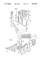
- FIGS. 1 and 2 are respectively three dimensional and schematic illustrations of an embodiment of the invention which employs a transmitted ray detector and a back scatter ray detector respectively along with associated displays;
- FIG. 3 is a schematic illustration of an embodiment of the invention which employs a transmitted ray detector, a back scatter ray detector and a forward ray detector and associated displays;
- FIG. 3A is an enlargement of one portion of FIG. 3 showing detectors in detail;
- FIGS. 4-6 schematically illustrate the events which occur interior of an object being imaged in response to illuminating radiation 30, and more specifically, a back scattering event, a forward scattering event and an absorption event, respectively;
- FIGS. 7 and 8 are respectively images produced by forward transmitted and back scatter detector in accordance with the invention.
- FIG. 9 is an illustration of an embodiment similar to FIG. 3 with the addition of a recorder 400.
- FIGS. 1 shows an isometric illustration of an embodiment of the invention which relies on simultaneous forward transmitted and back scattered x-ray detection to produce respectively independent, forward transmitted and back scatter images.
- a housing 160 is located adjacent a conveyor 80; the housing 160 includes an x-ray source and apparatus for forming, from the radiation emitted by the source, in turn, a sheet beam and then a flying pencil beam.
- the apparatus is arranged so that the pencil beam repeatedly sweeps a line in space at which is located a transmitted ray detector 50.
- a back scatter detector 25 Adjacent the locus along which the flying pencil beam emerges, is a back scatter detector 25 comprising detector elements 25A and 25B, located on either side of the slit through which the flying pencil beam emerges.
- the housing 160 also includes electronics for responding to signals produced by the forward transmitted detector 50 and the back scatter detector 25. In general, the electronics provides for analog to digital conversion and sampling, in order to generate an electrical signal capable of driving a video display.
- FIG. 2 is a schematic illustration of the same components.
- an x-ray source 15 produces a cone or fan of x-radiation which is directed at radiation opaque plate 20 with a slit 21 therein.
- the slit 21 allows a sheet-like x-ray beam to pass to a rotating disk 22 having one or more slits such as slit 24 located therein.
- the sheet beam emerging from the plate 20 has a dimension sufficient to illuminate approximately half the surface area of the rotating slotted wheel 22.
- a slit 24 intercepts the sheet beam allowing a pencil beam 30 to pass.
- the pencil beam 30 emitted by the slit 24 traverses a line in space.
- the transmitted ray detector 50 Located along that line in space is the transmitted ray detector 50.
- the detector 50 is located beyond the wheel 22 by a sufficient distance so that an object to be imaged such as the object 40 can pass therebetween.
- the conveyor 80 provides for motion of the object 40 in a direction 81 generally mutually perpendicular to the line in space at which the detector 50 is located and to the direction of the pencil beam.
- the pencil beam 30 scans the line in space occupied by the detector 50.
- the conveyor 80 provides for motion of the object 40 perpendicular to this line in space in the direction 81 at such a rate that the transmitted beam emerging from the object 40 can be used to generate a shadowgraph of the object 40 and its contents.
- FIG. 2 illustrates an x-ray source, a means for forming a flying pencil beam, a forward transmitted detector, associated electronics and display, those components may be identical to the apparatus shown in the '544 patent.
- FIG. 2 shows that a back scatter detector 25 has been added, which is located closer to the source 15 than is the object 40.
- the back scatter detector 25 may be formed into two components such as the detector elements 25A and 25B, located on either side of the slit through which the flying pencil beam emerges from the source 15.
- shielding is provided so that the detector 25 (or more particularly the elements 25A and 25B) are not exposed to direct illumination from the flying pencil beam 30.
- the detector elements 25A and 25B respond to back scattered radiation (to be described in connection with FIG. 4) and develop signals corresponding thereto. These signals are provided to the scatter electronics 251 where they may be summed and used to develop a video signal for driving a scatter imaging device or display 252.
- FIG. 3 is a schematic illustration of another embodiment of the invention which employs all three detectors. More particularly, the same reference characters in FIG. 3 identify apparatus corresponding to that shown in FIG. 2.
- FIG. 3 differs from the embodiment of FIGS. 1 and 2 by including a forward scatter detector comprising detector elements 60A and 60B. As seen in FIG. 3A the forward scatter detector elements 60A and 60B are substantially coplanar with the forward transmitted ray detector 50, although that is not essential.
- both forward scatter detector and transmitted ray detector 50 are further from the source 15 than the object.
- the signals generated by the forward scatter detector 60 are input to a forward scattered electronics 601 where by may be summed to drive a display 602.
- the transmitted electronics section 501, the forward scattered electronics 601 and back scattered electronics section 251 can be identical, providing for the analog to digital conversion and sampling functions already described to generate appropriate video signals. The only difference between these electronics sections is the signals which drive them.
- FIG. 3 shows that the signals from each of the detectors (the forward transmitted detector 50, the forward scatter detector 60 and the back scatter detector 25) are separately and independently used to generate corresponding video images displayed in the display devices 502, 602 and 252, respectively.
- FIG. 3A is an enlargement of the region of FIG. 3 shown in dotted outline, and includes one element 60A of the forward scatter detector and the forward transmitted detector 50.
- the element 60A includes an active element 61.
- the active element 61 has an active region which extends in two dimensions, one of those dimensions is perpendicular to the plane of the illustration, the other dimension is parallel to the arrow 60B.
- the length of the arrow 60B shows the length of this dimension of the active region of the elements 61.
- the forward transmitted detector 50 may consist of a detector (with an active element 51) in all other respects similar to the element 60A, but rotated (about an axis perpendicular to the sheet of the illustration) such that one dimension of the effective active region corresponds to the arrow 50B; it should be apparent that in this dimension the effective active regions of the elements 61 and 51 are significantly different.
- the forward transmitted detector element 51 need only have a sufficient effective active region to encompass the dimensions (50B) of the illuminating pencil beam 30.
- the effective active regions of the scatter detectors be significantly larger since their purpose is to capture energy which may be scattered at widely varying angles.
- the transmitted detector 50 has a dimension substantially equal to one dimension of the cross-section of beam 30; the scatter detector 25 and forward scatter detectors have all dimensions substantially larger than any dimension of the cross-section of beam 30.
- the two (or three) images that are derived be derived from the same flying spot x-ray beam which is a well-defined single beam. This ensures that the signal from any detector is associated with only one line of sight through the object being imaged, at any instant of time.
- the transmitted image is in effect a shadowgraph as described in the '544 patent.
- the back scattered and forward scattered images conversely, result from x-rays being scattered (particularly by Compton scattering) into the respective detectors (either forward or back).
- the advantage of the invention can be understood by reviewing the sequence of events from which a single element or pixel of the image is formed.
- the pencil beam 30 is illustrated as partially penetrating the object 40 until it reaches a point P.
- the pencil beam 30 is attenuated, and the extent of the attenuation depends upon the material lying in the path of the beam.
- the attenuation may be due to pure absorption (in which case one or more x-ray photons are completely removed, FIG. 6, from the beam and cannot contribute to any image direct or scattered) or the attenuation may also be due to scattering.
- the scattered beam is not captured by a detector, it too does not contribute to the image. To the extent that the beam is captured by a detector, then it will contribute to the image formed by the detector at which it is captured. In any case, the attenuated beam, as it reaches each depth within the object, may scatter. The scattered photon, in turn, may reach the detector only if it in turn, is not absorbed or scattered (redirected so as to miss a scatter receptive detector). Thus the probability of "seeing" a small sample within the object depends on three factors, as follows:
- the forward scattered image signal is weaker than the back scattered image signal in that all of the x-ray photons making up the forward scattered image signal must penetrate at least the entire object on the way to the forward scattered detector.
- the forward scatter image is subject to attenuation by that portion of the object between the scattering locus and the detector. It would also be inappropriate to sum the forward transmitted and any scatter signal. Since they highlight different materials, summing the signals would reduce the effectiveness of the result as compared to either signal alone.
- the transmitted image display 502 shows the conventional image that would have been shown by the display discussed in the '544 patent.
- the display 252 highlights low Z materials in that it preferentially is made up of more photons scattered from low Z materials than from high Z materials.
- the mental correlation by the viewer of the images displayed in the displays 502 and 252 provide a more useful picture of the contents of the object 40 than would be provided simply by the display 502 or the display 252, alone.
- the '544 patent suggests combining the forward transmitted and back scattered signals, for reasons discussed above, that is believed inappropriate.
- the transmitted images on the one hand and the scattered (either forward or back) images on the other hand can be differentiated in a different light.
- Visualizing the shape of a component in the x-ray illumination of an object requires the differentiation of the shape of the component from the background (from other different components which also lie in the path of the x-ray beam between the source and detector).
- the shapes we see are due to a component of an object preventing (either absorbing or scattering) x-ray photons from reaching the detector.
- the background is white or light (with the traditional processing referred to earlier), and the object visualized is black or dark. The more the component absorbs or scatters x-rays, the better will be its definition (i.e. contrast).
- the ratio of scattering to absorption is a critical parameter for the determination of how the image appears. This ratio changes dramatically with Z in the energy range of interest here. For low Z materials scatter dominates and for high Z material absorption dominates.
- the image produced by the scatter detectors depends of course not only on each sample (whether high Z or low Z) but also on the intervening components between the "sample” and the detector. There will be, in general, much more mass between the back scatter detector and the components of the object lying far from the back scatter detector than there will be between the back scatter detector and the components of the object lying near the back scatter detector. Of course, the opposite is true for the forward scatter detector, e.g. there is much more mass between "samples" located far from the forward scatter detector than there will be between "samples” lying near to the forward scatter detector. Hence in general the back scatter detector will preferentially display low Z materials lying closer to the back scatter detector whereas the forward scatter detector will preferentially display low Z materials lying closer to the forward scatter detector.
- FIGS. 7 and 8 illustrate the preferential display ability of the signals produced by the transmitted detector and back scatter detector, respectively.
- the illustrations in FIGS. 7 and 8 were derived from signals generated by a transmitted ray detector and a back scatter detector viewing an object illuminated in accordance with the invention, e.g. by using the common flying spot scanning pencil beam.
- FIG. 7 shows the contents of an attache case, clearly illuminating or differentiating the shape of high Z materials.
- the high Z components are emphasized, for example the speaker cone of the portable radio O3, the metal components of the umbrella O1 and the metal components of the travel case O2.
- the can of shaving cream O6 are examples of shaving cream O6.
- the background or regions of the object not occupied by high Z materials is relatively white or light, such that any low Z materials are difficult to identify or visualize.
- FIG. 8 in the image developed from back scatter signals some of the same objects can be identified, e.g. the umbrella O1 is also present, but note in this image the relatively lower Z handle is emphasized as opposed to the emphasis of the metal components in the image of FIG. 7.
- the travel case O2 is also recognizable, but in this case the low Z components are more readily identifiable than the higher Z components of the object O2 in FIG. 7.
- the portable radio O3 For example, in FIG. 8 we can no longer see the metal speaker cone.
- FIG. 8 shows us components of the object which are not visible in FIG. 7.
- FIG. 8 While the shoes or slippers O5 are visible in FIG. 8, more impressive is the visualization of the handgun O4.
- the handgun O4 in FIG. 8 is a plastic handgun and comparison between FIGS. 7 and 8 indicates how much more visible the handgun O4 is in FIG. 8 than it is in FIG. 7.
- the displays 602 and 252 provide the user with highlighted information concerning low Z materials.
- the back scatter detector highlights low Z materials closer to the source whereas the forward scatter detector highlights low Z materials further from the source.
- FIG. 3 provides the user with still additional information by reason of the presence of the transmitted display 502.
- Embodiments of the invention which have already been described produce images essentially in "real time". These are typically employed at airports and other similar regions where the owner of the object allows its inspection to gain access and hence quick inspection is advantageous. Other embodiments, however, do not necessarily require this "real time” feature. In other applications (for example nondestructive testing) it may not be necessary to view images created at the same time as the object is being illuminated.
- FIG. 9 is similar to FIG. 3 except that a recorder 400 is driven by the electronics 501, 601 and 251 to record signals produced in real time. The recorder 400 can then play the recorded signals back at any time to drive the displays 502, 602 and 252. Obviously the recorder 400 can be used with other embodiments of the invention in a similar fashion. It should also be apparent that other and still further variations can be employed within the spirit and scope of the invention which is to be construed in accordance with the attached claims.
Abstract
Description
Claims (8)
Priority Applications (1)
| Application Number | Priority Date | Filing Date | Title |
|---|---|---|---|
| US07809246 US5313511C1 (en) | 1986-06-20 | 1991-12-18 | X-ray imaging particularly adapted for low z materials |
Applications Claiming Priority (3)
| Application Number | Priority Date | Filing Date | Title |
|---|---|---|---|
| US06/876,632 US4799247A (en) | 1986-06-20 | 1986-06-20 | X-ray imaging particularly adapted for low Z materials |
| US21658688A | 1988-07-08 | 1988-07-08 | |
| US07809246 US5313511C1 (en) | 1986-06-20 | 1991-12-18 | X-ray imaging particularly adapted for low z materials |
Related Parent Applications (1)
| Application Number | Title | Priority Date | Filing Date |
|---|---|---|---|
| US21658688A Continuation | 1986-06-20 | 1988-07-08 |
Publications (2)
| Publication Number | Publication Date |
|---|---|
| US5313511A true US5313511A (en) | 1994-05-17 |
| US5313511C1 US5313511C1 (en) | 2001-01-30 |
Family
ID=25368214
Family Applications (2)
| Application Number | Title | Priority Date | Filing Date |
|---|---|---|---|
| US06/876,632 Expired - Lifetime US4799247A (en) | 1986-06-20 | 1986-06-20 | X-ray imaging particularly adapted for low Z materials |
| US07809246 Expired - Lifetime US5313511C1 (en) | 1986-06-20 | 1991-12-18 | X-ray imaging particularly adapted for low z materials |
Family Applications Before (1)
| Application Number | Title | Priority Date | Filing Date |
|---|---|---|---|
| US06/876,632 Expired - Lifetime US4799247A (en) | 1986-06-20 | 1986-06-20 | X-ray imaging particularly adapted for low Z materials |
Country Status (3)
| Country | Link |
|---|---|
| US (2) | US4799247A (en) |
| JP (1) | JP2641208B2 (en) |
| DE (1) | DE3719923C2 (en) |
Cited By (131)
| Publication number | Priority date | Publication date | Assignee | Title |
|---|---|---|---|---|
| US5590169A (en) * | 1995-01-09 | 1996-12-31 | Monteiro; Sergio L. P. | Radiation imaging system |
| US5642394A (en) * | 1996-04-03 | 1997-06-24 | American Science And Engineering, Inc. | Sidescatter X-ray detection system |
| US5764683A (en) * | 1996-02-12 | 1998-06-09 | American Science And Engineering, Inc. | Mobile X-ray inspection system for large objects |
| GB2329817A (en) * | 1997-09-29 | 1999-03-31 | Univ Nottingham Trent | X-ray detection and imaging of materials |
| US5917880A (en) * | 1997-05-29 | 1999-06-29 | Eg&G Astrophysics | X-ray inspection apparatus |
| WO1999033064A1 (en) * | 1997-12-19 | 1999-07-01 | American Science And Engineering, Inc. | X-ray ambient level safety system |
| WO1999039189A2 (en) * | 1998-01-28 | 1999-08-05 | American Science And Engineering, Inc. | Gated transmission and scatter detection for x-ray imaging |
| US6094472A (en) * | 1998-04-14 | 2000-07-25 | Rapiscan Security Products, Inc. | X-ray backscatter imaging system including moving body tracking assembly |
| US6094470A (en) * | 1996-02-14 | 2000-07-25 | Wesser & Dueholm | Method of determining the density profile |
| US6192104B1 (en) * | 1998-11-30 | 2001-02-20 | American Science And Engineering, Inc. | Fan and pencil beams from a common source for x-ray inspection |
| US6256404B1 (en) * | 1997-10-10 | 2001-07-03 | Analogic Corporation | Computed tomography scanning apparatus and method using adaptive reconstruction window |
| US6556653B2 (en) | 2000-05-25 | 2003-04-29 | University Of New Brunswick | Non-rotating X-ray system for three-dimensional, three-parameter imaging |
| US6658087B2 (en) | 2001-05-03 | 2003-12-02 | American Science And Engineering, Inc. | Nautical X-ray inspection system |
| US6661867B2 (en) | 2001-10-19 | 2003-12-09 | Control Screening, Llc | Tomographic scanning X-ray inspection system using transmitted and compton scattered radiation |
| US6665373B1 (en) | 2002-03-12 | 2003-12-16 | Rapiscan Security Products (Usa), Inc. | X-ray imaging system with active detector |
| US20040017888A1 (en) * | 2002-07-24 | 2004-01-29 | Seppi Edward J. | Radiation scanning of objects for contraband |
| US20040057554A1 (en) * | 2002-07-19 | 2004-03-25 | Paul Bjorkholm | Radiation sources and compact radiation scanning systems |
| US20040077849A1 (en) * | 2002-10-16 | 2004-04-22 | Orchid Chemicals & Pharmaceuticals Limited | Process for the preparation of cefadroxil |
| US20040086078A1 (en) * | 2002-11-06 | 2004-05-06 | William Adams | X-ray backscatter mobile inspection van |
| US20040213375A1 (en) * | 2003-04-25 | 2004-10-28 | Paul Bjorkholm | Radiation sources and radiation scanning systems with improved uniformity of radiation intensity |
| US20040256565A1 (en) * | 2002-11-06 | 2004-12-23 | William Adams | X-ray backscatter mobile inspection van |
| WO2005003817A2 (en) * | 2003-07-05 | 2005-01-13 | Smiths Heimann Gmbh | Device and method for examining objects by means of electromagnetic radiation |
| US20050089140A1 (en) * | 2001-10-19 | 2005-04-28 | Mario Arthur W. | Tomographic scanning X-ray inspection system using transmitted and compton scattered radiation |
| US20050157842A1 (en) * | 2002-07-23 | 2005-07-21 | Neeraj Agrawal | Single boom cargo scanning system |
| US20060023835A1 (en) * | 2002-12-04 | 2006-02-02 | Seppi Edward J | Radiation scanning units with reduced detector requirements |
| US20060043310A1 (en) * | 2004-08-27 | 2006-03-02 | Arsenault Paul J | X-ray scatter image reconstruction by balancing of discrepancies between detector responses, and apparatus therefor |
| US20060056584A1 (en) * | 2002-07-23 | 2006-03-16 | Bryan Allman | Self-contained mobile inspection system and method |
| US7110493B1 (en) * | 2002-02-28 | 2006-09-19 | Rapiscan Security Products (Usa), Inc. | X-ray detector system having low Z material panel |
| US20060245548A1 (en) * | 2005-04-22 | 2006-11-02 | Joseph Callerame | X-ray backscatter inspection with coincident optical beam |
| USRE39396E1 (en) * | 1996-02-12 | 2006-11-14 | American Science And Engineering, Inc. | Mobile x-ray inspection system for large objects |
| US20070098142A1 (en) * | 2005-10-24 | 2007-05-03 | Peter Rothschild | X-Ray Inspection Based on Scatter Detection |
| US20070172024A1 (en) * | 2003-04-25 | 2007-07-26 | Morton Edward J | X-ray scanning system |
| US20070172023A1 (en) * | 2003-04-25 | 2007-07-26 | Cxr Limited | Control means for heat load in x-ray scanning apparatus |
| US20070217572A1 (en) * | 2002-07-23 | 2007-09-20 | Andreas Kotowski | Single boom cargo scanning system |
| US20070269005A1 (en) * | 2002-11-06 | 2007-11-22 | Alex Chalmers | X-Ray Backscatter Detection Imaging Modules |
| US20070269007A1 (en) * | 2006-05-05 | 2007-11-22 | Alan Akery | Multiple pass cargo inspection system |
| US20080049899A1 (en) * | 2006-08-23 | 2008-02-28 | American Science And Engineering, Inc. | Scatter Attenuation Tomography |
| US7356115B2 (en) | 2002-12-04 | 2008-04-08 | Varian Medical Systems Technology, Inc. | Radiation scanning units including a movable platform |
| US20080144774A1 (en) * | 2003-04-25 | 2008-06-19 | Crx Limited | X-Ray Tubes |
| WO2008119969A2 (en) | 2007-03-29 | 2008-10-09 | Durham Scientific Crystals Limited | Imaging of materials |
| WO2008119967A2 (en) | 2007-03-29 | 2008-10-09 | Durham Scientific Crystals Limited | Imaging of materials |
| US20080253514A1 (en) * | 2005-02-25 | 2008-10-16 | Rapiscan Systems Limited | X-Ray Security Inspection Machine |
| US20080292050A1 (en) * | 2007-02-13 | 2008-11-27 | Sentinel Scanning Corporation | CT scanning and contraband detection |
| US20090010382A1 (en) * | 2003-04-25 | 2009-01-08 | Edward James Morton | X-Ray Monitoring |
| US20090010386A1 (en) * | 2003-09-15 | 2009-01-08 | Peschmann Kristian R | Methods and Systems for Rapid Detection of Concealed Objects Using Fluorescence |
| US20090103686A1 (en) * | 2007-10-23 | 2009-04-23 | American Science And Engineering, Inc. | X-Ray Imaging with Continuously Variable Zoom and Lateral Relative Displacement of the Source |
| US20090116614A1 (en) * | 2002-07-23 | 2009-05-07 | Andreas Kotowski | Cargo Scanning System |
| US20090141861A1 (en) * | 2004-05-21 | 2009-06-04 | Matthew Gaved | Penetrating Radiation Measurements |
| US20090161825A1 (en) * | 2003-06-20 | 2009-06-25 | James Carver | Relocatable X-Ray Imaging System and Method for Inspecting Commercial Vehicles and Cargo Containers |
| US7555099B2 (en) | 2006-08-11 | 2009-06-30 | American Science And Engineering, Inc. | X-ray inspection with contemporaneous and proximal transmission and backscatter imaging |
| US20090257555A1 (en) * | 2002-11-06 | 2009-10-15 | American Science And Engineering, Inc. | X-Ray Inspection Trailer |
| US20090274277A1 (en) * | 2003-04-25 | 2009-11-05 | Edward James Morton | X-Ray Sources |
| US20100034347A1 (en) * | 2006-08-23 | 2010-02-11 | American Science And Engineering, Inc. | Scatter Attenuation Tomography |
| US20100034451A1 (en) * | 2007-06-21 | 2010-02-11 | Hughes Ronald J | Systems and Methods for Improving Directed People Screening |
| US20100034353A1 (en) * | 2008-08-11 | 2010-02-11 | Kravis Scott D | Scanning X-ray inspection system using scintillation detection with simultaneous counting and integrating modes |
| US20100085066A1 (en) * | 2003-09-15 | 2010-04-08 | Peschmann Kristian R | Methods and systems for the rapid detection of concealed objects |
| WO2010070327A1 (en) | 2008-12-19 | 2010-06-24 | Durham Scientific Crystals Limited | Apparatus and method for characterisation of materials |
| US20100189226A1 (en) * | 2002-07-23 | 2010-07-29 | Andreas Kotowski | Rotatable boom cargo scanning system |
| US7826589B2 (en) | 2007-12-25 | 2010-11-02 | Rapiscan Systems, Inc. | Security system for screening people |
| CN101303317B (en) * | 2008-03-05 | 2010-11-17 | 中国科学院合肥物质科学研究院 | Explosive substance testing system apparatus and testing method thereof |
| US20100290691A1 (en) * | 2008-06-13 | 2010-11-18 | L-3 Communications Security And Detection Systems, Inc. | Examination of a region using dual-energy radiation |
| US20100303287A1 (en) * | 2003-04-25 | 2010-12-02 | Edward James Morton | X-Ray Tomographic Inspection Systems for the Identification of Specific Target Items |
| US20100303329A1 (en) * | 2003-04-25 | 2010-12-02 | Edward James Morton | Imaging, Data Acquisition, Data Transmission, and Data Distribution Methods and Systems for High Data Rate Tomographic X-Ray Scanners |
| US20100310037A1 (en) * | 2009-06-04 | 2010-12-09 | Ge Wang | Multi-Parameter X-Ray Computed Tomography |
| US20110004002A1 (en) * | 2008-02-29 | 2011-01-06 | Basf Se | Process for preparing alkyl 2-alkoxymethylene-4,4-difluoro-3-oxobutyrates |
| US20110026673A1 (en) * | 2009-07-29 | 2011-02-03 | American Science And Engineering, Inc. | Top-Down X-Ray Inspection Trailer |
| US20110038453A1 (en) * | 2002-07-23 | 2011-02-17 | Edward James Morton | Compact Mobile Cargo Scanning System |
| US7903789B2 (en) | 2003-04-25 | 2011-03-08 | Rapiscan Systems, Inc. | X-ray tube electron sources |
| US20110058646A1 (en) * | 2009-06-05 | 2011-03-10 | Michel Herranz | Transportation container inspection system and method |
| US20110064192A1 (en) * | 2002-07-23 | 2011-03-17 | Edward James Morton | Four Sided Imaging System and Method for Detection of Contraband |
| US20110081099A1 (en) * | 2007-02-01 | 2011-04-07 | Hughes Ronald J | Personnel Security Screening System with Enhanced Privacy |
| US20110098870A1 (en) * | 2008-02-28 | 2011-04-28 | Edward James Morton | Mobile Scanning Systems |
| US20110116600A1 (en) * | 2008-02-28 | 2011-05-19 | Edward James Morton | Scanning Systems |
| US20110116599A1 (en) * | 2008-02-28 | 2011-05-19 | Rapiscan Security Products, Inc. | Scanning Systems |
| US7949101B2 (en) | 2005-12-16 | 2011-05-24 | Rapiscan Systems, Inc. | X-ray scanners and X-ray sources therefor |
| US20110129063A1 (en) * | 2009-11-18 | 2011-06-02 | Joseph Bendahan | X-Ray-Based System and Methods for Inspecting a Person's Shoes for Aviation Security Threats |
| US20110135060A1 (en) * | 2008-05-20 | 2011-06-09 | Edward James Morton | High Energy X-Ray Inspection System Using a Fan-Shaped Beam and Collimated Backscatter Detectors |
| US20110135056A1 (en) * | 2008-05-20 | 2011-06-09 | Edward James Morton | Scanner Systems |
| US20110142203A1 (en) * | 2008-05-20 | 2011-06-16 | Edward James Morton | Gantry Scanner Systems |
| US8003949B2 (en) | 2007-11-01 | 2011-08-23 | Rapiscan Systems, Inc. | Multiple screen detection systems |
| US20110204243A1 (en) * | 2008-06-11 | 2011-08-25 | Joseph Bendahan | Composite Gamma-Neutron Detection System |
| US8094784B2 (en) | 2003-04-25 | 2012-01-10 | Rapiscan Systems, Inc. | X-ray sources |
| US8135110B2 (en) | 2005-12-16 | 2012-03-13 | Rapiscan Systems, Inc. | X-ray tomography inspection systems |
| US20120134467A1 (en) * | 2007-10-12 | 2012-05-31 | David Whittum | Charged particle accelerators, radiation sources, systems, and methods |
| US8213570B2 (en) | 2006-02-27 | 2012-07-03 | Rapiscan Systems, Inc. | X-ray security inspection machine |
| US8243876B2 (en) | 2003-04-25 | 2012-08-14 | Rapiscan Systems, Inc. | X-ray scanners |
| US8451974B2 (en) | 2003-04-25 | 2013-05-28 | Rapiscan Systems, Inc. | X-ray tomographic inspection system for the identification of specific target items |
| US8483351B2 (en) | 2009-10-28 | 2013-07-09 | Virginia Tech Intellectual Properties, Inc. | Cardiac computed tomography methods and systems using fast exact/quasi-exact filtered back projection algorithms |
| US8532823B2 (en) | 2010-02-12 | 2013-09-10 | American Science And Engineering, Inc. | Disruptor guidance system and methods based on scatter imaging |
| US8576989B2 (en) | 2010-03-14 | 2013-11-05 | Rapiscan Systems, Inc. | Beam forming apparatus |
| US8576982B2 (en) | 2008-02-01 | 2013-11-05 | Rapiscan Systems, Inc. | Personnel screening system |
| US8824637B2 (en) | 2008-09-13 | 2014-09-02 | Rapiscan Systems, Inc. | X-ray tubes |
| US8824632B2 (en) | 2009-07-29 | 2014-09-02 | American Science And Engineering, Inc. | Backscatter X-ray inspection van with top-down imaging |
| US8837669B2 (en) | 2003-04-25 | 2014-09-16 | Rapiscan Systems, Inc. | X-ray scanning system |
| US8842808B2 (en) | 2006-08-11 | 2014-09-23 | American Science And Engineering, Inc. | Scatter attenuation tomography using a monochromatic radiation source |
| US8908831B2 (en) | 2011-02-08 | 2014-12-09 | Rapiscan Systems, Inc. | Covert surveillance using multi-modality sensing |
| US8963094B2 (en) | 2008-06-11 | 2015-02-24 | Rapiscan Systems, Inc. | Composite gamma-neutron detection system |
| US8971485B2 (en) | 2008-02-28 | 2015-03-03 | Rapiscan Systems, Inc. | Drive-through scanning systems |
| US8995619B2 (en) | 2010-03-14 | 2015-03-31 | Rapiscan Systems, Inc. | Personnel screening system |
| US9036779B2 (en) | 2008-02-28 | 2015-05-19 | Rapiscan Systems, Inc. | Dual mode X-ray vehicle scanning system |
| US9057679B2 (en) | 2012-02-03 | 2015-06-16 | Rapiscan Systems, Inc. | Combined scatter and transmission multi-view imaging system |
| US9113839B2 (en) | 2003-04-25 | 2015-08-25 | Rapiscon Systems, Inc. | X-ray inspection system and method |
| US9208988B2 (en) | 2005-10-25 | 2015-12-08 | Rapiscan Systems, Inc. | Graphite backscattered electron shield for use in an X-ray tube |
| US9218933B2 (en) | 2011-06-09 | 2015-12-22 | Rapidscan Systems, Inc. | Low-dose radiographic imaging system |
| US9223050B2 (en) | 2005-04-15 | 2015-12-29 | Rapiscan Systems, Inc. | X-ray imaging system having improved mobility |
| US9223052B2 (en) | 2008-02-28 | 2015-12-29 | Rapiscan Systems, Inc. | Scanning systems |
| US9263225B2 (en) | 2008-07-15 | 2016-02-16 | Rapiscan Systems, Inc. | X-ray tube anode comprising a coolant tube |
| US9285325B2 (en) | 2007-02-01 | 2016-03-15 | Rapiscan Systems, Inc. | Personnel screening system |
| US9310323B2 (en) | 2009-05-16 | 2016-04-12 | Rapiscan Systems, Inc. | Systems and methods for high-Z threat alarm resolution |
| US9420677B2 (en) | 2009-01-28 | 2016-08-16 | Rapiscan Systems, Inc. | X-ray tube electron sources |
| US9486839B2 (en) | 2011-01-07 | 2016-11-08 | Huron Valley Steel Corporation | Scrap metal sorting system |
| US9557427B2 (en) | 2014-01-08 | 2017-01-31 | Rapiscan Systems, Inc. | Thin gap chamber neutron detectors |
| US9632205B2 (en) | 2011-02-08 | 2017-04-25 | Rapiscan Systems, Inc. | Covert surveillance using multi-modality sensing |
| US9726619B2 (en) | 2005-10-25 | 2017-08-08 | Rapiscan Systems, Inc. | Optimization of the source firing pattern for X-ray scanning systems |
| US9791590B2 (en) | 2013-01-31 | 2017-10-17 | Rapiscan Systems, Inc. | Portable security inspection system |
| US9823383B2 (en) | 2013-01-07 | 2017-11-21 | Rapiscan Systems, Inc. | X-ray scanner with partial energy discriminating detector array |
| US9891314B2 (en) | 2014-03-07 | 2018-02-13 | Rapiscan Systems, Inc. | Ultra wide band detectors |
| US9958569B2 (en) | 2002-07-23 | 2018-05-01 | Rapiscan Systems, Inc. | Mobile imaging system and method for detection of contraband |
| US10134254B2 (en) | 2014-11-25 | 2018-11-20 | Rapiscan Systems, Inc. | Intelligent security management system |
| US10345479B2 (en) | 2015-09-16 | 2019-07-09 | Rapiscan Systems, Inc. | Portable X-ray scanner |
| US10483077B2 (en) | 2003-04-25 | 2019-11-19 | Rapiscan Systems, Inc. | X-ray sources having reduced electron scattering |
| US10720300B2 (en) | 2016-09-30 | 2020-07-21 | American Science And Engineering, Inc. | X-ray source for 2D scanning beam imaging |
| US11175245B1 (en) | 2020-06-15 | 2021-11-16 | American Science And Engineering, Inc. | Scatter X-ray imaging with adaptive scanning beam intensity |
| US11280898B2 (en) | 2014-03-07 | 2022-03-22 | Rapiscan Systems, Inc. | Radar-based baggage and parcel inspection systems |
| US11300703B2 (en) | 2015-03-20 | 2022-04-12 | Rapiscan Systems, Inc. | Hand-held portable backscatter inspection system |
| US11340361B1 (en) | 2020-11-23 | 2022-05-24 | American Science And Engineering, Inc. | Wireless transmission detector panel for an X-ray scanner |
| US11525930B2 (en) | 2018-06-20 | 2022-12-13 | American Science And Engineering, Inc. | Wavelength-shifting sheet-coupled scintillation detectors |
| US11551903B2 (en) | 2020-06-25 | 2023-01-10 | American Science And Engineering, Inc. | Devices and methods for dissipating heat from an anode of an x-ray tube assembly |
| US11579327B2 (en) | 2012-02-14 | 2023-02-14 | American Science And Engineering, Inc. | Handheld backscatter imaging systems with primary and secondary detector arrays |
| US11778717B2 (en) | 2020-06-30 | 2023-10-03 | VEC Imaging GmbH & Co. KG | X-ray source with multiple grids |
| US11796489B2 (en) | 2021-02-23 | 2023-10-24 | Rapiscan Systems, Inc. | Systems and methods for eliminating cross-talk signals in one or more scanning systems having multiple X-ray sources |
Families Citing this family (39)
| Publication number | Priority date | Publication date | Assignee | Title |
|---|---|---|---|---|
| EP0247491B1 (en) * | 1986-05-28 | 1990-08-16 | Heimann GmbH | X-ray scanning system |
| US5044002A (en) * | 1986-07-14 | 1991-08-27 | Hologic, Inc. | Baggage inspection and the like |
| US4974247A (en) * | 1987-11-24 | 1990-11-27 | The Boeing Company | System for radiographically inspecting an object using backscattered radiation and related method |
| US5007072A (en) * | 1988-08-03 | 1991-04-09 | Ion Track Instruments | X-ray diffraction inspection system |
| US5138553A (en) * | 1989-03-10 | 1992-08-11 | Expert Image Systems, Inc. | Method and apparatus for bone mineral measurement using a measurement region defined at a selected distance from a styloid bone tip |
| US5022062A (en) * | 1989-09-13 | 1991-06-04 | American Science And Engineering, Inc. | Automatic threat detection based on illumination by penetrating radiant energy using histogram processing |
| US5179581A (en) * | 1989-09-13 | 1993-01-12 | American Science And Engineering, Inc. | Automatic threat detection based on illumination by penetrating radiant energy |
| US4987582A (en) * | 1989-10-19 | 1991-01-22 | Hughes Aircraft Company | X-ray fluorescence imaging of elements |
| US5181234B1 (en) * | 1990-08-06 | 2000-01-04 | Rapiscan Security Products Inc | X-ray backscatter detection system |
| US5105452A (en) * | 1991-03-26 | 1992-04-14 | Mcinerney Joseph J | Device for determining the characteristics of blood flow through coronary bypass grafts |
| JPH04353792A (en) * | 1991-05-31 | 1992-12-08 | Toshiba Corp | Scattered ray imaging device and scattered ray detector used for it |
| US5799106A (en) * | 1991-07-09 | 1998-08-25 | The United States Of America As Represented By The Secretary Of The Air Force | Noise immune automated contrast control for infrared cameras |
| US5253283A (en) * | 1991-12-23 | 1993-10-12 | American Science And Engineering, Inc. | Inspection method and apparatus with single color pixel imaging |
| US5600303A (en) * | 1993-01-15 | 1997-02-04 | Technology International Incorporated | Detection of concealed explosives and contraband |
| DE4306187A1 (en) * | 1993-02-27 | 1994-09-01 | Industrieanlagen Betriebsges | Method and arrangement of devices for protecting buildings and people against violent offenders |
| US5428657A (en) * | 1994-03-22 | 1995-06-27 | Georgia Tech Research Corporation | X-ray monitoring system |
| US5481584A (en) * | 1994-11-23 | 1996-01-02 | Tang; Jihong | Device for material separation using nondestructive inspection imaging |
| US5600700A (en) * | 1995-09-25 | 1997-02-04 | Vivid Technologies, Inc. | Detecting explosives or other contraband by employing transmitted and scattered X-rays |
| US5974111A (en) * | 1996-09-24 | 1999-10-26 | Vivid Technologies, Inc. | Identifying explosives or other contraband by employing transmitted or scattered X-rays |
| US6278115B1 (en) * | 1998-08-28 | 2001-08-21 | Annistech, Inc. | X-ray inspection system detector with plastic scintillating material |
| US6459764B1 (en) | 1999-01-27 | 2002-10-01 | American Science And Engineering, Inc. | Drive-through vehicle inspection system |
| US6546072B1 (en) * | 1999-07-30 | 2003-04-08 | American Science And Engineering, Inc. | Transmission enhanced scatter imaging |
| US6269142B1 (en) | 1999-08-11 | 2001-07-31 | Steven W. Smith | Interrupted-fan-beam imaging |
| US6879657B2 (en) * | 2002-05-10 | 2005-04-12 | Ge Medical Systems Global Technology, Llc | Computed tomography system with integrated scatter detectors |
| US20030226971A1 (en) * | 2002-06-11 | 2003-12-11 | Chandross Edwin Arthur | Nuclear radiation detector |
| US7809109B2 (en) * | 2004-04-09 | 2010-10-05 | American Science And Engineering, Inc. | Multiple image collection and synthesis for personnel screening |
| EP1733213B1 (en) * | 2004-04-09 | 2010-02-24 | American Science & Engineering, Inc. | Eliminating cross-talk in a backscatter inspection portal comprising multiples sources by ensuring that only one source is emitting radiation at a time |
| WO2006053279A2 (en) * | 2004-11-12 | 2006-05-18 | Scantech Holdings, Llc | Non-intrusive container inspection system using forward-scattered radiation |
| WO2006138521A2 (en) * | 2005-06-16 | 2006-12-28 | Ii-Vi Incorporated | Energy discriminating scatter imaging system |
| EP2010943A2 (en) * | 2006-04-21 | 2009-01-07 | American Science & Engineering, Inc. | X-ray imaging of baggage and personnel using arrays of discrete sources and multiple collimated beams |
| WO2009101572A2 (en) * | 2008-02-14 | 2009-08-20 | Koninklijke Philips Electronics N.V. | X- ray apparatus, particularly for security applications |
| FR3000211B1 (en) | 2012-12-20 | 2015-12-11 | Commissariat Energie Atomique | SCANNING LIGHTING DEVICE, IMAGING DEVICE COMPRISING SAME, AND METHOD FOR OPERATING SAME |
| EP3221722A1 (en) | 2014-11-20 | 2017-09-27 | Heuresis Corporation | X-ray scanning system |
| CN105301669B (en) | 2015-12-04 | 2019-01-04 | 同方威视技术股份有限公司 | Rays safety detection apparatus and X-ray detection X method |
| US10770195B2 (en) | 2017-04-05 | 2020-09-08 | Viken Detection Corporation | X-ray chopper wheel assembly |
| CN108227027B (en) * | 2017-12-29 | 2020-12-01 | 同方威视技术股份有限公司 | Vehicle-mounted backscatter inspection system |
| CN108008458B (en) * | 2017-12-29 | 2020-09-08 | 同方威视技术股份有限公司 | Vehicle-mounted backscatter inspection system |
| BR112022001635A2 (en) * | 2019-08-02 | 2022-07-12 | Videray Tech Inc | CLOSED X-RAY CUTTING WHEEL |
| CN115698774A (en) | 2020-06-02 | 2023-02-03 | 维肯检测公司 | X-ray imaging apparatus and method |
Citations (2)
| Publication number | Priority date | Publication date | Assignee | Title |
|---|---|---|---|---|
| US3780291A (en) * | 1971-07-07 | 1973-12-18 | American Science & Eng Inc | Radiant energy imaging with scanning pencil beam |
| US4123654A (en) * | 1975-10-03 | 1978-10-31 | Siemens Aktiengesellschaft | Method for determining the density of bodies by means of penetrating rays and apparatus for carrying out said method |
Family Cites Families (24)
| Publication number | Priority date | Publication date | Assignee | Title |
|---|---|---|---|---|
| US28544A (en) * | 1860-06-05 | Ditching-machine | ||
| US2977478A (en) * | 1953-11-11 | 1961-03-28 | Exatest Ges Fur Messtechnik Mi | Method of and apparatus for measuring the thickness of materials |
| US2966587A (en) * | 1955-08-02 | 1960-12-27 | Tracerlab Inc | Hydrogen measurement |
| US3210545A (en) * | 1961-07-24 | 1965-10-05 | Industrial Nucleonics Corp | Method of compensating a radiation gauge for unwanted changes in measured material |
| FR1389417A (en) * | 1963-04-01 | 1965-02-19 | Commissariat Energie Atomique | Dosing method and devices by applying |
| USRE28544E (en) * | 1971-07-07 | 1975-09-02 | Radiant energy imaging with scanning pencil beam | |
| US3754138A (en) * | 1971-10-07 | 1973-08-21 | Industrial Nucleonics Corp | Inner layer position measurement |
| DK134687B (en) * | 1972-11-22 | 1976-12-20 | Isotopcentralen | Apparatus for measuring the concentration of one or more elements in a carrier medium by means of gamma or X-rays. |
| DK131955C (en) * | 1973-10-09 | 1976-02-23 | I Leunbach | PROCEDURE AND SYSTEM FOR DETERMINING THE ELECTRONITY OF A PART VOLUME OF A BODY |
| US3914607A (en) * | 1973-12-12 | 1975-10-21 | Industrial Nucleonics Corp | Thickness measuring apparatus and method for tire ply and similar materials |
| US3927318A (en) * | 1974-05-06 | 1975-12-16 | Albert Macovski | Cross-sectional fluorescent imaging system |
| US3965353A (en) * | 1974-12-06 | 1976-06-22 | Albert Macovski | Cross-sectional X-ray emission imaging system |
| JPS6013789B2 (en) * | 1975-07-01 | 1985-04-09 | イプレツツ エス.エイ. | Composite plate polishing tool |
| US4031545A (en) * | 1975-09-08 | 1977-06-21 | American Science & Engineering, Inc. | Radiant energy alarm system |
| US3980568A (en) * | 1975-10-17 | 1976-09-14 | Hankison Corporation | Radiation detection system |
| US4047029A (en) * | 1976-07-02 | 1977-09-06 | Allport John J | Self-compensating X-ray or γ-ray thickness gauge |
| US4147931A (en) * | 1976-12-13 | 1979-04-03 | Pertti Puumalainen | Procedure for measuring unit area weights |
| US4228351A (en) * | 1979-02-26 | 1980-10-14 | The United States Of America As Represented By The United States Department Of Energy | Method for measuring the density of lightweight materials |
| DE2926456A1 (en) * | 1979-06-30 | 1981-01-15 | Philips Patentverwaltung | METHOD FOR DETERMINING THE EDGE OF A BODY BY MEANS OF SPRAYED RADIATION |
| US4266425A (en) * | 1979-11-09 | 1981-05-12 | Zikonix Corporation | Method for continuously determining the composition and mass flow of butter and similar substances from a manufacturing process |
| US4357535A (en) * | 1980-04-30 | 1982-11-02 | North American Philips Corporation | Apparatus for inspecting hand-held articles and persons carrying same |
| US4495636A (en) * | 1981-01-02 | 1985-01-22 | Research Corporation | Multichannel radiography employing scattered radiation |
| FR2507779A1 (en) * | 1981-06-15 | 1982-12-17 | Charbonnages De France | METHOD AND APPARATUS FOR MEDIUM-NEW EXPLOSIMETRY OF BREAKING DOUBTS |
| DE3406905A1 (en) * | 1984-02-25 | 1985-09-05 | Philips Patentverwaltung Gmbh, 2000 Hamburg | ROENTGENGERAET |
-
1986
- 1986-06-20 US US06/876,632 patent/US4799247A/en not_active Expired - Lifetime
-
1987
- 1987-05-18 JP JP62121002A patent/JP2641208B2/en not_active Expired - Lifetime
- 1987-06-15 DE DE3719923A patent/DE3719923C2/en not_active Expired - Lifetime
-
1991
- 1991-12-18 US US07809246 patent/US5313511C1/en not_active Expired - Lifetime
Patent Citations (2)
| Publication number | Priority date | Publication date | Assignee | Title |
|---|---|---|---|---|
| US3780291A (en) * | 1971-07-07 | 1973-12-18 | American Science & Eng Inc | Radiant energy imaging with scanning pencil beam |
| US4123654A (en) * | 1975-10-03 | 1978-10-31 | Siemens Aktiengesellschaft | Method for determining the density of bodies by means of penetrating rays and apparatus for carrying out said method |
Non-Patent Citations (2)
| Title |
|---|
| Kawatra et al., "The On-Line Measurements of Ash in Coal Slurries", Can. J. Spectrosc., vol. 21, No. 2, Mar./Apr. 1976, pp. 58-60. |
| Kawatra et al., The On Line Measurements of Ash in Coal Slurries , Can. J. Spectrosc., vol. 21, No. 2, Mar./Apr. 1976, pp. 58 60. * |
Cited By (312)
| Publication number | Priority date | Publication date | Assignee | Title |
|---|---|---|---|---|
| US5590169A (en) * | 1995-01-09 | 1996-12-31 | Monteiro; Sergio L. P. | Radiation imaging system |
| US6252929B1 (en) | 1996-02-12 | 2001-06-26 | American Science & Engineering, Inc. | Mobile x-ray inspection system for large objects |
| US5764683A (en) * | 1996-02-12 | 1998-06-09 | American Science And Engineering, Inc. | Mobile X-ray inspection system for large objects |
| USRE39396E1 (en) * | 1996-02-12 | 2006-11-14 | American Science And Engineering, Inc. | Mobile x-ray inspection system for large objects |
| US6292533B1 (en) | 1996-02-12 | 2001-09-18 | American Science & Engineering, Inc. | Mobile X-ray inspection system for large objects |
| US6094470A (en) * | 1996-02-14 | 2000-07-25 | Wesser & Dueholm | Method of determining the density profile |
| US5642394A (en) * | 1996-04-03 | 1997-06-24 | American Science And Engineering, Inc. | Sidescatter X-ray detection system |
| US5917880A (en) * | 1997-05-29 | 1999-06-29 | Eg&G Astrophysics | X-ray inspection apparatus |
| GB2329817A (en) * | 1997-09-29 | 1999-03-31 | Univ Nottingham Trent | X-ray detection and imaging of materials |
| GB2329817B (en) * | 1997-09-29 | 2001-08-29 | Univ Nottingham Trent | Detecting,improving and characterising material in 3-D space |
| US6256404B1 (en) * | 1997-10-10 | 2001-07-03 | Analogic Corporation | Computed tomography scanning apparatus and method using adaptive reconstruction window |
| WO1999033064A1 (en) * | 1997-12-19 | 1999-07-01 | American Science And Engineering, Inc. | X-ray ambient level safety system |
| WO1999039189A2 (en) * | 1998-01-28 | 1999-08-05 | American Science And Engineering, Inc. | Gated transmission and scatter detection for x-ray imaging |
| WO1999039189A3 (en) * | 1998-01-28 | 1999-09-30 | American Science & Eng Inc | Gated transmission and scatter detection for x-ray imaging |
| US6151381A (en) * | 1998-01-28 | 2000-11-21 | American Science And Engineering, Inc. | Gated transmission and scatter detection for x-ray imaging |
| US6094472A (en) * | 1998-04-14 | 2000-07-25 | Rapiscan Security Products, Inc. | X-ray backscatter imaging system including moving body tracking assembly |
| US6192104B1 (en) * | 1998-11-30 | 2001-02-20 | American Science And Engineering, Inc. | Fan and pencil beams from a common source for x-ray inspection |
| US6556653B2 (en) | 2000-05-25 | 2003-04-29 | University Of New Brunswick | Non-rotating X-ray system for three-dimensional, three-parameter imaging |
| US6658087B2 (en) | 2001-05-03 | 2003-12-02 | American Science And Engineering, Inc. | Nautical X-ray inspection system |
| US6661867B2 (en) | 2001-10-19 | 2003-12-09 | Control Screening, Llc | Tomographic scanning X-ray inspection system using transmitted and compton scattered radiation |
| US7072440B2 (en) | 2001-10-19 | 2006-07-04 | Control Screening, Llc | Tomographic scanning X-ray inspection system using transmitted and Compton scattered radiation |
| US20050089140A1 (en) * | 2001-10-19 | 2005-04-28 | Mario Arthur W. | Tomographic scanning X-ray inspection system using transmitted and compton scattered radiation |
| US7110493B1 (en) * | 2002-02-28 | 2006-09-19 | Rapiscan Security Products (Usa), Inc. | X-ray detector system having low Z material panel |
| US6665373B1 (en) | 2002-03-12 | 2003-12-16 | Rapiscan Security Products (Usa), Inc. | X-ray imaging system with active detector |
| US7162005B2 (en) | 2002-07-19 | 2007-01-09 | Varian Medical Systems Technologies, Inc. | Radiation sources and compact radiation scanning systems |
| US20040057554A1 (en) * | 2002-07-19 | 2004-03-25 | Paul Bjorkholm | Radiation sources and compact radiation scanning systems |
| US20060056584A1 (en) * | 2002-07-23 | 2006-03-16 | Bryan Allman | Self-contained mobile inspection system and method |
| US20070217572A1 (en) * | 2002-07-23 | 2007-09-20 | Andreas Kotowski | Single boom cargo scanning system |
| US8929509B2 (en) | 2002-07-23 | 2015-01-06 | Rapiscan Systems, Inc. | Four-sided imaging system and method for detection of contraband |
| US20050157842A1 (en) * | 2002-07-23 | 2005-07-21 | Neeraj Agrawal | Single boom cargo scanning system |
| US9052403B2 (en) | 2002-07-23 | 2015-06-09 | Rapiscan Systems, Inc. | Compact mobile cargo scanning system |
| US20110116597A1 (en) * | 2002-07-23 | 2011-05-19 | Neeraj Agrawal | Cargo Scanning System |
| US7817776B2 (en) | 2002-07-23 | 2010-10-19 | Rapiscan Systems, Inc. | Cargo scanning system |
| US7995705B2 (en) | 2002-07-23 | 2011-08-09 | Rapiscan Security Products, Inc. | Self-contained mobile inspection system and method |
| US9025731B2 (en) | 2002-07-23 | 2015-05-05 | Rapiscan Systems, Inc. | Cargo scanning system |
| US7783004B2 (en) | 2002-07-23 | 2010-08-24 | Rapiscan Systems, Inc. | Cargo scanning system |
| US20100189226A1 (en) * | 2002-07-23 | 2010-07-29 | Andreas Kotowski | Rotatable boom cargo scanning system |
| US20110038453A1 (en) * | 2002-07-23 | 2011-02-17 | Edward James Morton | Compact Mobile Cargo Scanning System |
| US9223049B2 (en) | 2002-07-23 | 2015-12-29 | Rapiscan Systems, Inc. | Cargo scanning system with boom structure |
| US20110064192A1 (en) * | 2002-07-23 | 2011-03-17 | Edward James Morton | Four Sided Imaging System and Method for Detection of Contraband |
| US7720195B2 (en) | 2002-07-23 | 2010-05-18 | Rapiscan Security Products, Inc. | Self-contained mobile inspection system and method |
| US9020096B2 (en) | 2002-07-23 | 2015-04-28 | Rapiscan Systems, Inc. | Self contained mobile inspection system and method |
| US8687765B2 (en) | 2002-07-23 | 2014-04-01 | Rapiscan Systems, Inc. | Cargo scanning system with boom structure |
| US8059781B2 (en) | 2002-07-23 | 2011-11-15 | Rapiscan Systems, Inc. | Cargo scanning system |
| US8668386B2 (en) | 2002-07-23 | 2014-03-11 | Rapiscan Systems, Inc. | Compact mobile cargo scanning system |
| US8503605B2 (en) | 2002-07-23 | 2013-08-06 | Rapiscan Systems, Inc. | Four sided imaging system and method for detection of contraband |
| US20090274270A1 (en) * | 2002-07-23 | 2009-11-05 | Andreas Kotowski | Single Boom Cargo Scanning System |
| US7876880B2 (en) | 2002-07-23 | 2011-01-25 | Rapiscan Systems, Inc. | Single boom cargo scanning system |
| US8491189B2 (en) | 2002-07-23 | 2013-07-23 | Rapiscan Systems, Inc. | Radiation source apparatus |
| US20090245462A1 (en) * | 2002-07-23 | 2009-10-01 | Neeraj Agrawal | Cargo Scanning System |
| US7322745B2 (en) | 2002-07-23 | 2008-01-29 | Rapiscan Security Products, Inc. | Single boom cargo scanning system |
| US11143783B2 (en) | 2002-07-23 | 2021-10-12 | Rapiscan Systems, Inc. | Four-sided imaging system and method for detection of contraband |
| US20080075232A1 (en) * | 2002-07-23 | 2008-03-27 | Neeraj Agrawal | Cargo Scanning System |
| US20090202037A1 (en) * | 2002-07-23 | 2009-08-13 | Bryan Allman | Self-Contained Mobile Inspection System and Method |
| US7369643B2 (en) | 2002-07-23 | 2008-05-06 | Rapiscan Security Products, Inc. | Single boom cargo scanning system |
| US7963695B2 (en) | 2002-07-23 | 2011-06-21 | Rapiscan Systems, Inc. | Rotatable boom cargo scanning system |
| US8385501B2 (en) | 2002-07-23 | 2013-02-26 | Rapiscan Systems, Inc. | Self contained mobile inspection system and method |
| US9958569B2 (en) | 2002-07-23 | 2018-05-01 | Rapiscan Systems, Inc. | Mobile imaging system and method for detection of contraband |
| US20080165926A1 (en) * | 2002-07-23 | 2008-07-10 | Andreas Kotowski | Single Boom Cargo Scanning System |
| US8356937B2 (en) | 2002-07-23 | 2013-01-22 | Rapiscan Systems, Inc. | Rotatable boom cargo scanning system |
| US10976465B2 (en) | 2002-07-23 | 2021-04-13 | Rapiscan Systems, Inc. | Two-sided, multi-energy imaging system and method for the inspection of cargo |
| US20090116614A1 (en) * | 2002-07-23 | 2009-05-07 | Andreas Kotowski | Cargo Scanning System |
| US8275091B2 (en) | 2002-07-23 | 2012-09-25 | Rapiscan Systems, Inc. | Compact mobile cargo scanning system |
| US10007019B2 (en) | 2002-07-23 | 2018-06-26 | Rapiscan Systems, Inc. | Compact mobile cargo scanning system |
| US10670769B2 (en) | 2002-07-23 | 2020-06-02 | Rapiscan Systems, Inc. | Compact mobile cargo scanning system |
| US7517149B2 (en) | 2002-07-23 | 2009-04-14 | Rapiscan Security Products, Inc. | Cargo scanning system |
| US7519148B2 (en) | 2002-07-23 | 2009-04-14 | Rapiscan Security Products, Inc. | Single boom cargo scanning system |
| US7486768B2 (en) | 2002-07-23 | 2009-02-03 | Rapiscan Security Products, Inc. | Self-contained mobile inspection system and method |
| US8000436B2 (en) | 2002-07-24 | 2011-08-16 | Varian Medical Systems, Inc. | Radiation scanning units including a movable platform |
| US20080205583A1 (en) * | 2002-07-24 | 2008-08-28 | Seppi Edward J | Radiation scanning of objects for contraband |
| US7672422B2 (en) | 2002-07-24 | 2010-03-02 | Varian Medical Systems, Inc. | Radiation scanning of objects for contraband |
| US20040017888A1 (en) * | 2002-07-24 | 2004-01-29 | Seppi Edward J. | Radiation scanning of objects for contraband |
| US20070003003A1 (en) * | 2002-07-24 | 2007-01-04 | Seppi Edward J | Radiation scanning of objects for contraband |
| US7103137B2 (en) | 2002-07-24 | 2006-09-05 | Varian Medical Systems Technology, Inc. | Radiation scanning of objects for contraband |
| US7369640B2 (en) | 2002-07-24 | 2008-05-06 | Varian Medical Systems Technologies, Inc. | Radiation scanning of objects for contraband |
| US20040077849A1 (en) * | 2002-10-16 | 2004-04-22 | Orchid Chemicals & Pharmaceuticals Limited | Process for the preparation of cefadroxil |
| US20040256565A1 (en) * | 2002-11-06 | 2004-12-23 | William Adams | X-ray backscatter mobile inspection van |
| US8194822B2 (en) | 2002-11-06 | 2012-06-05 | American Science And Engineering, Inc. | X-ray inspection based on scatter detection |
| US20040086078A1 (en) * | 2002-11-06 | 2004-05-06 | William Adams | X-ray backscatter mobile inspection van |
| US7099434B2 (en) | 2002-11-06 | 2006-08-29 | American Science And Engineering, Inc. | X-ray backscatter mobile inspection van |
| US7218704B1 (en) | 2002-11-06 | 2007-05-15 | American Science And Engineering, Inc. | X-ray backscatter mobile inspection van |
| US20110075808A1 (en) * | 2002-11-06 | 2011-03-31 | American Science And Engineering, Inc. | X-Ray Inspection Based on Scatter Detection |
| US7505556B2 (en) | 2002-11-06 | 2009-03-17 | American Science And Engineering, Inc. | X-ray backscatter detection imaging modules |
| US20090257555A1 (en) * | 2002-11-06 | 2009-10-15 | American Science And Engineering, Inc. | X-Ray Inspection Trailer |
| US20070269005A1 (en) * | 2002-11-06 | 2007-11-22 | Alex Chalmers | X-Ray Backscatter Detection Imaging Modules |
| US20060023835A1 (en) * | 2002-12-04 | 2006-02-02 | Seppi Edward J | Radiation scanning units with reduced detector requirements |
| US7356115B2 (en) | 2002-12-04 | 2008-04-08 | Varian Medical Systems Technology, Inc. | Radiation scanning units including a movable platform |
| US7672426B2 (en) | 2002-12-04 | 2010-03-02 | Varian Medical Systems, Inc. | Radiation scanning units with reduced detector requirements |
| US9747705B2 (en) | 2003-04-25 | 2017-08-29 | Rapiscan Systems, Inc. | Imaging, data acquisition, data transmission, and data distribution methods and systems for high data rate tomographic X-ray scanners |
| US20100195788A1 (en) * | 2003-04-25 | 2010-08-05 | Edward James Morton | X-Ray Scanning System |
| US20090316855A1 (en) * | 2003-04-25 | 2009-12-24 | Edward James Morton | Control Means for Heat Load in X-Ray Scanning Apparatus |
| US9618648B2 (en) | 2003-04-25 | 2017-04-11 | Rapiscan Systems, Inc. | X-ray scanners |
| US9442082B2 (en) | 2003-04-25 | 2016-09-13 | Rapiscan Systems, Inc. | X-ray inspection system and method |
| US20070172024A1 (en) * | 2003-04-25 | 2007-07-26 | Morton Edward J | X-ray scanning system |
| US20070172023A1 (en) * | 2003-04-25 | 2007-07-26 | Cxr Limited | Control means for heat load in x-ray scanning apparatus |
| US7664230B2 (en) | 2003-04-25 | 2010-02-16 | Rapiscan Systems, Inc. | X-ray tubes |
| US20090274277A1 (en) * | 2003-04-25 | 2009-11-05 | Edward James Morton | X-Ray Sources |
| US11796711B2 (en) | 2003-04-25 | 2023-10-24 | Rapiscan Systems, Inc. | Modular CT scanning system |
| US7684538B2 (en) | 2003-04-25 | 2010-03-23 | Rapiscan Systems, Inc. | X-ray scanning system |
| US8085897B2 (en) | 2003-04-25 | 2011-12-27 | Rapiscan Systems, Inc. | X-ray scanning system |
| US8804899B2 (en) | 2003-04-25 | 2014-08-12 | Rapiscan Systems, Inc. | Imaging, data acquisition, data transmission, and data distribution methods and systems for high data rate tomographic X-ray scanners |
| US20090010382A1 (en) * | 2003-04-25 | 2009-01-08 | Edward James Morton | X-Ray Monitoring |
| US7724868B2 (en) | 2003-04-25 | 2010-05-25 | Rapiscan Systems, Inc. | X-ray monitoring |
| US8094784B2 (en) | 2003-04-25 | 2012-01-10 | Rapiscan Systems, Inc. | X-ray sources |
| US20100172476A1 (en) * | 2003-04-25 | 2010-07-08 | Edward James Morton | X-Ray Tubes |
| US7564939B2 (en) | 2003-04-25 | 2009-07-21 | Rapiscan Systems, Inc. | Control means for heat load in X-ray scanning apparatus |
| US8837669B2 (en) | 2003-04-25 | 2014-09-16 | Rapiscan Systems, Inc. | X-ray scanning system |
| US9675306B2 (en) | 2003-04-25 | 2017-06-13 | Rapiscan Systems, Inc. | X-ray scanning system |
| US8451974B2 (en) | 2003-04-25 | 2013-05-28 | Rapiscan Systems, Inc. | X-ray tomographic inspection system for the identification of specific target items |
| US8223919B2 (en) | 2003-04-25 | 2012-07-17 | Rapiscan Systems, Inc. | X-ray tomographic inspection systems for the identification of specific target items |
| US8243876B2 (en) | 2003-04-25 | 2012-08-14 | Rapiscan Systems, Inc. | X-ray scanners |
| US8885794B2 (en) | 2003-04-25 | 2014-11-11 | Rapiscan Systems, Inc. | X-ray tomographic inspection system for the identification of specific target items |
| US9183647B2 (en) | 2003-04-25 | 2015-11-10 | Rapiscan Systems, Inc. | Imaging, data acquisition, data transmission, and data distribution methods and systems for high data rate tomographic X-ray scanners |
| US20100303287A1 (en) * | 2003-04-25 | 2010-12-02 | Edward James Morton | X-Ray Tomographic Inspection Systems for the Identification of Specific Target Items |
| US20100303329A1 (en) * | 2003-04-25 | 2010-12-02 | Edward James Morton | Imaging, Data Acquisition, Data Transmission, and Data Distribution Methods and Systems for High Data Rate Tomographic X-Ray Scanners |
| US9113839B2 (en) | 2003-04-25 | 2015-08-25 | Rapiscon Systems, Inc. | X-ray inspection system and method |
| US7929663B2 (en) | 2003-04-25 | 2011-04-19 | Rapiscan Systems, Inc. | X-ray monitoring |
| US6954515B2 (en) | 2003-04-25 | 2005-10-11 | Varian Medical Systems, Inc., | Radiation sources and radiation scanning systems with improved uniformity of radiation intensity |
| US20080144774A1 (en) * | 2003-04-25 | 2008-06-19 | Crx Limited | X-Ray Tubes |
| US10901112B2 (en) | 2003-04-25 | 2021-01-26 | Rapiscan Systems, Inc. | X-ray scanning system with stationary x-ray sources |
| US20040213375A1 (en) * | 2003-04-25 | 2004-10-28 | Paul Bjorkholm | Radiation sources and radiation scanning systems with improved uniformity of radiation intensity |
| US9001973B2 (en) | 2003-04-25 | 2015-04-07 | Rapiscan Systems, Inc. | X-ray sources |
| US7903789B2 (en) | 2003-04-25 | 2011-03-08 | Rapiscan Systems, Inc. | X-ray tube electron sources |
| US9020095B2 (en) | 2003-04-25 | 2015-04-28 | Rapiscan Systems, Inc. | X-ray scanners |
| US10175381B2 (en) | 2003-04-25 | 2019-01-08 | Rapiscan Systems, Inc. | X-ray scanners having source points with less than a predefined variation in brightness |
| US10591424B2 (en) | 2003-04-25 | 2020-03-17 | Rapiscan Systems, Inc. | X-ray tomographic inspection systems for the identification of specific target items |
| US10483077B2 (en) | 2003-04-25 | 2019-11-19 | Rapiscan Systems, Inc. | X-ray sources having reduced electron scattering |
| US20090161825A1 (en) * | 2003-06-20 | 2009-06-25 | James Carver | Relocatable X-Ray Imaging System and Method for Inspecting Commercial Vehicles and Cargo Containers |
| US9285498B2 (en) | 2003-06-20 | 2016-03-15 | Rapiscan Systems, Inc. | Relocatable X-ray imaging system and method for inspecting commercial vehicles and cargo containers |
| US7769133B2 (en) | 2003-06-20 | 2010-08-03 | Rapiscan Systems, Inc. | Relocatable X-ray imaging system and method for inspecting commercial vehicles and cargo containers |
| US7991113B2 (en) | 2003-06-20 | 2011-08-02 | Rapiscan Security Products, Inc. | Relocatable x-ray imaging system and method for inspecting commercial vehicles and cargo containers |
| WO2005003817A2 (en) * | 2003-07-05 | 2005-01-13 | Smiths Heimann Gmbh | Device and method for examining objects by means of electromagnetic radiation |
| WO2005003817A3 (en) * | 2003-07-05 | 2005-06-30 | Smiths Heimann Gmbh | Device and method for examining objects by means of electromagnetic radiation |
| US20080137809A1 (en) * | 2003-07-05 | 2008-06-12 | Smiths Heimann Gmbh | Device and method for inspecting objects |
| US7457394B2 (en) | 2003-07-05 | 2008-11-25 | Smiths Heimann Gmbh | Device and method for inspecting objects |
| US9042511B2 (en) | 2003-08-08 | 2015-05-26 | Rapiscan Systems, Inc. | Methods and systems for the rapid detection of concealed objects |
| US9915752B2 (en) | 2003-08-08 | 2018-03-13 | Rapiscan Systems, Inc. | Inspection systems with two X-ray scanners in a first stage inspection system |
| US20110228896A1 (en) * | 2003-09-15 | 2011-09-22 | Peschmann Kristian R | Methods and Systems for Rapid Detection of Concealed Objects Using Fluorescence |
| US20090010386A1 (en) * | 2003-09-15 | 2009-01-08 | Peschmann Kristian R | Methods and Systems for Rapid Detection of Concealed Objects Using Fluorescence |
| US9268058B2 (en) | 2003-09-15 | 2016-02-23 | Rapiscan Systems, Inc. | Methods and systems for the rapid detection of concealed objects |
| US8138770B2 (en) | 2003-09-15 | 2012-03-20 | Rapiscan Systems, Inc. | Methods and systems for the rapid detection of concealed objects |
| US8428217B2 (en) | 2003-09-15 | 2013-04-23 | Rapiscan Systems, Inc. | Methods and systems for rapid detection of concealed objects |
| US7856081B2 (en) | 2003-09-15 | 2010-12-21 | Rapiscan Systems, Inc. | Methods and systems for rapid detection of concealed objects using fluorescence |
| US8674706B2 (en) | 2003-09-15 | 2014-03-18 | Rapiscan Systems, Inc. | Methods and systems for the rapid detection of concealed objects |
| US20100085066A1 (en) * | 2003-09-15 | 2010-04-08 | Peschmann Kristian R | Methods and systems for the rapid detection of concealed objects |
| US20090141861A1 (en) * | 2004-05-21 | 2009-06-04 | Matthew Gaved | Penetrating Radiation Measurements |
| US20060043310A1 (en) * | 2004-08-27 | 2006-03-02 | Arsenault Paul J | X-ray scatter image reconstruction by balancing of discrepancies between detector responses, and apparatus therefor |
| US7203276B2 (en) | 2004-08-27 | 2007-04-10 | University Of New Brunswick | X-ray scatter image reconstruction by balancing of discrepancies between detector responses, and apparatus therefor |
| US20080253514A1 (en) * | 2005-02-25 | 2008-10-16 | Rapiscan Systems Limited | X-Ray Security Inspection Machine |
| US7702069B2 (en) | 2005-02-25 | 2010-04-20 | Rapiscan Security Products, Inc. | X-ray security inspection machine |
| US9223050B2 (en) | 2005-04-15 | 2015-12-29 | Rapiscan Systems, Inc. | X-ray imaging system having improved mobility |
| US20060245548A1 (en) * | 2005-04-22 | 2006-11-02 | Joseph Callerame | X-ray backscatter inspection with coincident optical beam |
| US7551715B2 (en) | 2005-10-24 | 2009-06-23 | American Science And Engineering, Inc. | X-ray inspection based on scatter detection |
| US20070098142A1 (en) * | 2005-10-24 | 2007-05-03 | Peter Rothschild | X-Ray Inspection Based on Scatter Detection |
| US9208988B2 (en) | 2005-10-25 | 2015-12-08 | Rapiscan Systems, Inc. | Graphite backscattered electron shield for use in an X-ray tube |
| US9726619B2 (en) | 2005-10-25 | 2017-08-08 | Rapiscan Systems, Inc. | Optimization of the source firing pattern for X-ray scanning systems |
| US8135110B2 (en) | 2005-12-16 | 2012-03-13 | Rapiscan Systems, Inc. | X-ray tomography inspection systems |
| US10976271B2 (en) | 2005-12-16 | 2021-04-13 | Rapiscan Systems, Inc. | Stationary tomographic X-ray imaging systems for automatically sorting objects based on generated tomographic images |
| US8625735B2 (en) | 2005-12-16 | 2014-01-07 | Rapiscan Systems, Inc. | X-ray scanners and X-ray sources therefor |
| US9638646B2 (en) | 2005-12-16 | 2017-05-02 | Rapiscan Systems, Inc. | X-ray scanners and X-ray sources therefor |
| US10295483B2 (en) | 2005-12-16 | 2019-05-21 | Rapiscan Systems, Inc. | Data collection, processing and storage systems for X-ray tomographic images |
| US8958526B2 (en) | 2005-12-16 | 2015-02-17 | Rapiscan Systems, Inc. | Data collection, processing and storage systems for X-ray tomographic images |
| US9048061B2 (en) | 2005-12-16 | 2015-06-02 | Rapiscan Systems, Inc. | X-ray scanners and X-ray sources therefor |
| US7949101B2 (en) | 2005-12-16 | 2011-05-24 | Rapiscan Systems, Inc. | X-ray scanners and X-ray sources therefor |
| US8213570B2 (en) | 2006-02-27 | 2012-07-03 | Rapiscan Systems, Inc. | X-ray security inspection machine |
| US9310322B2 (en) | 2006-02-27 | 2016-04-12 | Rapiscan Systems, Inc. | X-ray security inspection machine |
| US20070269007A1 (en) * | 2006-05-05 | 2007-11-22 | Alan Akery | Multiple pass cargo inspection system |
| US7526064B2 (en) | 2006-05-05 | 2009-04-28 | Rapiscan Security Products, Inc. | Multiple pass cargo inspection system |
| US7860213B2 (en) | 2006-05-05 | 2010-12-28 | Rapiscan Systems, Inc. | Multiple pass cargo inspection system |
| US8170177B2 (en) | 2006-05-05 | 2012-05-01 | Rapiscan Systems, Inc. | Multiple pass cargo inspection system |
| US20110127426A1 (en) * | 2006-05-05 | 2011-06-02 | Alan Akery | Multiple Pass Cargo Inspection System |
| US8457275B2 (en) | 2006-05-05 | 2013-06-04 | Rapiscan Systems, Inc. | Multiple pass cargo inspection system |
| US8837670B2 (en) | 2006-05-05 | 2014-09-16 | Rapiscan Systems, Inc. | Cargo inspection system |
| US9279901B2 (en) | 2006-05-05 | 2016-03-08 | Rapiscan Systems, Inc. | Cargo inspection system |
| US20090268871A1 (en) * | 2006-08-11 | 2009-10-29 | American Science And Engineering, Inc. | X-Ray Inspection with Contemporaneous and Proximal Transmission and Backscatter Imaging |
| US8842808B2 (en) | 2006-08-11 | 2014-09-23 | American Science And Engineering, Inc. | Scatter attenuation tomography using a monochromatic radiation source |
| US7555099B2 (en) | 2006-08-11 | 2009-06-30 | American Science And Engineering, Inc. | X-ray inspection with contemporaneous and proximal transmission and backscatter imaging |
| US7995707B2 (en) | 2006-08-11 | 2011-08-09 | American Science And Engineering, Inc. | X-ray inspection with contemporaneous and proximal transmission and backscatter imaging |
| US7924979B2 (en) | 2006-08-23 | 2011-04-12 | American Science And Engineering, Inc. | Scatter attenuation tomography |
| US20100034347A1 (en) * | 2006-08-23 | 2010-02-11 | American Science And Engineering, Inc. | Scatter Attenuation Tomography |
| US7551718B2 (en) | 2006-08-23 | 2009-06-23 | American Science And Engineering, Inc. | Scatter attenuation tomography |
| US20080049899A1 (en) * | 2006-08-23 | 2008-02-28 | American Science And Engineering, Inc. | Scatter Attenuation Tomography |
| US8135112B2 (en) | 2007-02-01 | 2012-03-13 | Rapiscan Systems, Inc. | Personnel security screening system with enhanced privacy |
| US9285325B2 (en) | 2007-02-01 | 2016-03-15 | Rapiscan Systems, Inc. | Personnel screening system |
| US9182516B2 (en) | 2007-02-01 | 2015-11-10 | Rapiscan Systems, Inc. | Personnel screening system |
| US20110081099A1 (en) * | 2007-02-01 | 2011-04-07 | Hughes Ronald J | Personnel Security Screening System with Enhanced Privacy |
| US9291741B2 (en) | 2007-02-01 | 2016-03-22 | Rapiscan Systems, Inc. | Personnel screening system |
| US20110163239A1 (en) * | 2007-02-13 | 2011-07-07 | Sentinel Scanning Corporation | CT Scanning and Contraband Detection |
| US20080292050A1 (en) * | 2007-02-13 | 2008-11-27 | Sentinel Scanning Corporation | CT scanning and contraband detection |
| US7929664B2 (en) | 2007-02-13 | 2011-04-19 | Sentinel Scanning Corporation | CT scanning and contraband detection |
| US8254517B2 (en) | 2007-02-13 | 2012-08-28 | Sentinel Scanning Corporation | CT scanning and contraband detection |
| WO2008119967A3 (en) * | 2007-03-29 | 2008-12-11 | Durham Scient Crystals | Imaging of materials |
| CN101641614B (en) * | 2007-03-29 | 2012-07-04 | 克罗梅克有限公司 | Imaging of materials |
| US7634051B2 (en) | 2007-03-29 | 2009-12-15 | Durham Scientific Crystals Limited | Imaging of materials |
| US7656995B2 (en) | 2007-03-29 | 2010-02-02 | Durham Scientific Crystals Ltd. | Imaging of materials |
| WO2008119969A2 (en) | 2007-03-29 | 2008-10-09 | Durham Scientific Crystals Limited | Imaging of materials |
| WO2008119967A2 (en) | 2007-03-29 | 2008-10-09 | Durham Scientific Crystals Limited | Imaging of materials |
| CN101657738B (en) * | 2007-03-29 | 2013-04-17 | 克罗梅克有限公司 | Imaging of materials |
| WO2008119969A3 (en) * | 2007-03-29 | 2008-12-04 | Durham Scient Crystals | Imaging of materials |
| US20100034451A1 (en) * | 2007-06-21 | 2010-02-11 | Hughes Ronald J | Systems and Methods for Improving Directed People Screening |
| US8774362B2 (en) | 2007-06-21 | 2014-07-08 | Rapiscan Systems, Inc. | Systems and methods for improving directed people screening |
| US8199996B2 (en) | 2007-06-21 | 2012-06-12 | Rapiscan Systems, Inc. | Systems and methods for improving directed people screening |
| US10314151B2 (en) | 2007-10-12 | 2019-06-04 | Varex Imaging Corporation | Charged particle accelerators, radiation sources, systems, and methods |
| US20120134467A1 (en) * | 2007-10-12 | 2012-05-31 | David Whittum | Charged particle accelerators, radiation sources, systems, and methods |
| US9030134B2 (en) * | 2007-10-12 | 2015-05-12 | Vanan Medical Systems, Inc. | Charged particle accelerators, radiation sources, systems, and methods |
| US20090103686A1 (en) * | 2007-10-23 | 2009-04-23 | American Science And Engineering, Inc. | X-Ray Imaging with Continuously Variable Zoom and Lateral Relative Displacement of the Source |
| US7593510B2 (en) | 2007-10-23 | 2009-09-22 | American Science And Engineering, Inc. | X-ray imaging with continuously variable zoom and lateral relative displacement of the source |
| US8003949B2 (en) | 2007-11-01 | 2011-08-23 | Rapiscan Systems, Inc. | Multiple screen detection systems |
| US8401147B2 (en) | 2007-11-01 | 2013-03-19 | Rapiscan Systems, Inc. | Multiple screen detection systems |
| US8148693B2 (en) | 2007-11-01 | 2012-04-03 | Rapiscan Systems, Inc. | Multiple screen detection systems |
| US7826589B2 (en) | 2007-12-25 | 2010-11-02 | Rapiscan Systems, Inc. | Security system for screening people |
| US8576982B2 (en) | 2008-02-01 | 2013-11-05 | Rapiscan Systems, Inc. | Personnel screening system |
| US8774357B2 (en) | 2008-02-28 | 2014-07-08 | Rapiscan Systems, Inc. | Scanning systems |
| US10754058B2 (en) | 2008-02-28 | 2020-08-25 | Rapiscan Systems, Inc. | Drive-through scanning systems |
| US10816691B2 (en) | 2008-02-28 | 2020-10-27 | Rapiscan Systems, Inc. | Multi-element detector systems |
| US8971485B2 (en) | 2008-02-28 | 2015-03-03 | Rapiscan Systems, Inc. | Drive-through scanning systems |
| US10585207B2 (en) | 2008-02-28 | 2020-03-10 | Rapiscan Systems, Inc. | Scanning systems |
| US8433036B2 (en) | 2008-02-28 | 2013-04-30 | Rapiscan Systems, Inc. | Scanning systems |
| US11275194B2 (en) | 2008-02-28 | 2022-03-15 | Rapiscan Systems, Inc. | Scanning systems |
| US9036779B2 (en) | 2008-02-28 | 2015-05-19 | Rapiscan Systems, Inc. | Dual mode X-ray vehicle scanning system |
| US9223052B2 (en) | 2008-02-28 | 2015-12-29 | Rapiscan Systems, Inc. | Scanning systems |
| US10007021B2 (en) | 2008-02-28 | 2018-06-26 | Rapiscan Systems, Inc. | Scanning systems |
| US20110098870A1 (en) * | 2008-02-28 | 2011-04-28 | Edward James Morton | Mobile Scanning Systems |
| US20110116599A1 (en) * | 2008-02-28 | 2011-05-19 | Rapiscan Security Products, Inc. | Scanning Systems |
| US9835756B2 (en) | 2008-02-28 | 2017-12-05 | Rapiscan Systems, Inc. | Dual mode X-ray vehicle scanning system |
| US11579328B2 (en) | 2008-02-28 | 2023-02-14 | Rapiscan Systems, Inc. | Drive-through scanning systems |
| US9121958B2 (en) | 2008-02-28 | 2015-09-01 | Rapiscan Systems, Inc. | Scanning systems |
| US9158027B2 (en) | 2008-02-28 | 2015-10-13 | Rapiscan Systems, Inc. | Mobile scanning systems |
| US9817151B2 (en) | 2008-02-28 | 2017-11-14 | Rapiscan Systems, Inc. | Drive-through scanning systems |
| US11768313B2 (en) | 2008-02-28 | 2023-09-26 | Rapiscan Systems, Inc. | Multi-scanner networked systems for performing material discrimination processes on scanned objects |
| US9429530B2 (en) | 2008-02-28 | 2016-08-30 | Rapiscan Systems, Inc. | Scanning systems |
| US8644453B2 (en) | 2008-02-28 | 2014-02-04 | Rapiscan Systems, Inc. | Scanning systems |
| US20110116600A1 (en) * | 2008-02-28 | 2011-05-19 | Edward James Morton | Scanning Systems |
| US20110004002A1 (en) * | 2008-02-29 | 2011-01-06 | Basf Se | Process for preparing alkyl 2-alkoxymethylene-4,4-difluoro-3-oxobutyrates |
| CN101303317B (en) * | 2008-03-05 | 2010-11-17 | 中国科学院合肥物质科学研究院 | Explosive substance testing system apparatus and testing method thereof |
| US20110135060A1 (en) * | 2008-05-20 | 2011-06-09 | Edward James Morton | High Energy X-Ray Inspection System Using a Fan-Shaped Beam and Collimated Backscatter Detectors |
| US9332624B2 (en) | 2008-05-20 | 2016-05-03 | Rapiscan Systems, Inc. | Gantry scanner systems |
| US8831176B2 (en) | 2008-05-20 | 2014-09-09 | Rapiscan Systems, Inc. | High energy X-ray inspection system using a fan-shaped beam and collimated backscatter detectors |
| US8579506B2 (en) | 2008-05-20 | 2013-11-12 | Rapiscan Systems, Inc. | Gantry scanner systems |
| US9688517B2 (en) | 2008-05-20 | 2017-06-27 | Rapiscan Systems, Inc. | Scanner systems |
| US8840303B2 (en) | 2008-05-20 | 2014-09-23 | Rapiscan Systems, Inc. | Scanner systems |
| US20110135056A1 (en) * | 2008-05-20 | 2011-06-09 | Edward James Morton | Scanner Systems |
| US20110142203A1 (en) * | 2008-05-20 | 2011-06-16 | Edward James Morton | Gantry Scanner Systems |
| US10098214B2 (en) | 2008-05-20 | 2018-10-09 | Rapiscan Systems, Inc. | Detector support structures for gantry scanner systems |
| US8389941B2 (en) | 2008-06-11 | 2013-03-05 | Rapiscan Systems, Inc. | Composite gamma-neutron detection system |
| US8963094B2 (en) | 2008-06-11 | 2015-02-24 | Rapiscan Systems, Inc. | Composite gamma-neutron detection system |
| US9329285B2 (en) | 2008-06-11 | 2016-05-03 | Rapiscan Systems, Inc. | Composite gamma-neutron detection system |
| US8735833B2 (en) | 2008-06-11 | 2014-05-27 | Rapiscan Systems, Inc | Photomultiplier and detection systems |
| US20110204243A1 (en) * | 2008-06-11 | 2011-08-25 | Joseph Bendahan | Composite Gamma-Neutron Detection System |
| US8389942B2 (en) | 2008-06-11 | 2013-03-05 | Rapiscan Systems, Inc. | Photomultiplier and detection systems |
| US8993970B2 (en) | 2008-06-11 | 2015-03-31 | Rapiscan Systems, Inc. | Photomultiplier and detection systems |
| US20100290691A1 (en) * | 2008-06-13 | 2010-11-18 | L-3 Communications Security And Detection Systems, Inc. | Examination of a region using dual-energy radiation |
| US8401270B2 (en) | 2008-06-13 | 2013-03-19 | L-3 Communications Security And Detection Systems, Inc. | Examination of a region using dual-energy radiation |
| US9263225B2 (en) | 2008-07-15 | 2016-02-16 | Rapiscan Systems, Inc. | X-ray tube anode comprising a coolant tube |
| US20100034353A1 (en) * | 2008-08-11 | 2010-02-11 | Kravis Scott D | Scanning X-ray inspection system using scintillation detection with simultaneous counting and integrating modes |
| US7965816B2 (en) | 2008-08-11 | 2011-06-21 | Control Screening, LLC. | Scanning X-ray inspection system using scintillation detection with simultaneous counting and integrating modes |
| US8824637B2 (en) | 2008-09-13 | 2014-09-02 | Rapiscan Systems, Inc. | X-ray tubes |
| WO2010070327A1 (en) | 2008-12-19 | 2010-06-24 | Durham Scientific Crystals Limited | Apparatus and method for characterisation of materials |
| US8781072B2 (en) | 2008-12-19 | 2014-07-15 | Kromek Limited | Apparatus and method for characterisation of materials |
| US9420677B2 (en) | 2009-01-28 | 2016-08-16 | Rapiscan Systems, Inc. | X-ray tube electron sources |
| US9625606B2 (en) | 2009-05-16 | 2017-04-18 | Rapiscan Systems, Inc. | Systems and methods for high-Z threat alarm resolution |
| US9310323B2 (en) | 2009-05-16 | 2016-04-12 | Rapiscan Systems, Inc. | Systems and methods for high-Z threat alarm resolution |
| US20100310037A1 (en) * | 2009-06-04 | 2010-12-09 | Ge Wang | Multi-Parameter X-Ray Computed Tomography |
| US8121249B2 (en) * | 2009-06-04 | 2012-02-21 | Virginia Tech Intellectual Properties, Inc. | Multi-parameter X-ray computed tomography |
| US8340245B2 (en) | 2009-06-05 | 2012-12-25 | Sentinel Scanning Corporation | Transportation container inspection system and method |
| US20110058646A1 (en) * | 2009-06-05 | 2011-03-10 | Michel Herranz | Transportation container inspection system and method |
| US8345819B2 (en) | 2009-07-29 | 2013-01-01 | American Science And Engineering, Inc. | Top-down X-ray inspection trailer |
| US8824632B2 (en) | 2009-07-29 | 2014-09-02 | American Science And Engineering, Inc. | Backscatter X-ray inspection van with top-down imaging |
| US20110026673A1 (en) * | 2009-07-29 | 2011-02-03 | American Science And Engineering, Inc. | Top-Down X-Ray Inspection Trailer |
| US8483351B2 (en) | 2009-10-28 | 2013-07-09 | Virginia Tech Intellectual Properties, Inc. | Cardiac computed tomography methods and systems using fast exact/quasi-exact filtered back projection algorithms |
| US20110129063A1 (en) * | 2009-11-18 | 2011-06-02 | Joseph Bendahan | X-Ray-Based System and Methods for Inspecting a Person's Shoes for Aviation Security Threats |
| US8654922B2 (en) | 2009-11-18 | 2014-02-18 | Rapiscan Systems, Inc. | X-ray-based system and methods for inspecting a person's shoes for aviation security threats |
| US8532823B2 (en) | 2010-02-12 | 2013-09-10 | American Science And Engineering, Inc. | Disruptor guidance system and methods based on scatter imaging |
| US9058909B2 (en) | 2010-03-14 | 2015-06-16 | Rapiscan Systems, Inc. | Beam forming apparatus |
| US8995619B2 (en) | 2010-03-14 | 2015-03-31 | Rapiscan Systems, Inc. | Personnel screening system |
| US8576989B2 (en) | 2010-03-14 | 2013-11-05 | Rapiscan Systems, Inc. | Beam forming apparatus |
| US9486839B2 (en) | 2011-01-07 | 2016-11-08 | Huron Valley Steel Corporation | Scrap metal sorting system |
| US10408967B2 (en) | 2011-02-08 | 2019-09-10 | Rapiscan Systems, Inc. | Covert surveillance using multi-modality sensing |
| US9562866B2 (en) | 2011-02-08 | 2017-02-07 | Rapiscan Systems, Inc. | Covert surveillance using multi-modality sensing |
| US11822041B2 (en) | 2011-02-08 | 2023-11-21 | Rapiscan Systems, Inc. | Systems and methods for improved atomic-number based material discrimination |
| US11307325B2 (en) | 2011-02-08 | 2022-04-19 | Rapiscan Systems, Inc. | Covert surveillance using multi-modality sensing |
| US10942291B2 (en) | 2011-02-08 | 2021-03-09 | Rapiscan Systems, Inc. | Covert surveillance using multi-modality sensing |
| US9632205B2 (en) | 2011-02-08 | 2017-04-25 | Rapiscan Systems, Inc. | Covert surveillance using multi-modality sensing |
| US8908831B2 (en) | 2011-02-08 | 2014-12-09 | Rapiscan Systems, Inc. | Covert surveillance using multi-modality sensing |
| US9218933B2 (en) | 2011-06-09 | 2015-12-22 | Rapidscan Systems, Inc. | Low-dose radiographic imaging system |
| US9823201B2 (en) | 2012-02-03 | 2017-11-21 | Rapiscan Systems, Inc. | Combined scatter and transmission multi-view imaging system |
| US11371948B2 (en) | 2012-02-03 | 2022-06-28 | Rapiscan Systems, Inc. | Multi-view imaging system |
| US10746674B2 (en) | 2012-02-03 | 2020-08-18 | Rapiscan Systems, Inc. | Combined scatter and transmission multi-view imaging system |
| US9057679B2 (en) | 2012-02-03 | 2015-06-16 | Rapiscan Systems, Inc. | Combined scatter and transmission multi-view imaging system |
| US11579327B2 (en) | 2012-02-14 | 2023-02-14 | American Science And Engineering, Inc. | Handheld backscatter imaging systems with primary and secondary detector arrays |
| US9823383B2 (en) | 2013-01-07 | 2017-11-21 | Rapiscan Systems, Inc. | X-ray scanner with partial energy discriminating detector array |
| US10353109B2 (en) | 2013-01-07 | 2019-07-16 | Rapiscan Systems, Inc. | X-ray scanner with partial energy discriminating detector array |
| US10782440B2 (en) | 2013-01-07 | 2020-09-22 | Rapiscan Systems, Inc. | X-ray scanner with partial energy discriminating detector array |
| US10317566B2 (en) | 2013-01-31 | 2019-06-11 | Rapiscan Systems, Inc. | Portable security inspection system |
| US11550077B2 (en) | 2013-01-31 | 2023-01-10 | Rapiscan Systems, Inc. | Portable vehicle inspection portal with accompanying workstation |
| US9791590B2 (en) | 2013-01-31 | 2017-10-17 | Rapiscan Systems, Inc. | Portable security inspection system |
| US9557427B2 (en) | 2014-01-08 | 2017-01-31 | Rapiscan Systems, Inc. | Thin gap chamber neutron detectors |
| US11280898B2 (en) | 2014-03-07 | 2022-03-22 | Rapiscan Systems, Inc. | Radar-based baggage and parcel inspection systems |
| US9891314B2 (en) | 2014-03-07 | 2018-02-13 | Rapiscan Systems, Inc. | Ultra wide band detectors |
| US10134254B2 (en) | 2014-11-25 | 2018-11-20 | Rapiscan Systems, Inc. | Intelligent security management system |
| US10713914B2 (en) | 2014-11-25 | 2020-07-14 | Rapiscan Systems, Inc. | Intelligent security management system |
| US11561320B2 (en) | 2015-03-20 | 2023-01-24 | Rapiscan Systems, Inc. | Hand-held portable backscatter inspection system |
| US11300703B2 (en) | 2015-03-20 | 2022-04-12 | Rapiscan Systems, Inc. | Hand-held portable backscatter inspection system |
| US10345479B2 (en) | 2015-09-16 | 2019-07-09 | Rapiscan Systems, Inc. | Portable X-ray scanner |
| US10720300B2 (en) | 2016-09-30 | 2020-07-21 | American Science And Engineering, Inc. | X-ray source for 2D scanning beam imaging |
| US11525930B2 (en) | 2018-06-20 | 2022-12-13 | American Science And Engineering, Inc. | Wavelength-shifting sheet-coupled scintillation detectors |
| US11175245B1 (en) | 2020-06-15 | 2021-11-16 | American Science And Engineering, Inc. | Scatter X-ray imaging with adaptive scanning beam intensity |
| US11551903B2 (en) | 2020-06-25 | 2023-01-10 | American Science And Engineering, Inc. | Devices and methods for dissipating heat from an anode of an x-ray tube assembly |
| US11778717B2 (en) | 2020-06-30 | 2023-10-03 | VEC Imaging GmbH & Co. KG | X-ray source with multiple grids |
| US11340361B1 (en) | 2020-11-23 | 2022-05-24 | American Science And Engineering, Inc. | Wireless transmission detector panel for an X-ray scanner |
| US11726218B2 (en) | 2020-11-23 | 2023-08-15 | American Science arid Engineering, Inc. | Methods and systems for synchronizing backscatter signals and wireless transmission signals in x-ray scanning |
| US11796489B2 (en) | 2021-02-23 | 2023-10-24 | Rapiscan Systems, Inc. | Systems and methods for eliminating cross-talk signals in one or more scanning systems having multiple X-ray sources |
Also Published As
| Publication number | Publication date |
|---|---|
| DE3719923C2 (en) | 1998-07-02 |
| US5313511C1 (en) | 2001-01-30 |
| DE3719923A1 (en) | 1987-12-23 |
| JP2641208B2 (en) | 1997-08-13 |
| US4799247A (en) | 1989-01-17 |
| JPS6325537A (en) | 1988-02-03 |
Similar Documents
| Publication | Publication Date | Title |
|---|---|---|
| US5313511A (en) | X-ray imaging particularly adapted for low Z materials | |
| US5642394A (en) | Sidescatter X-ray detection system | |
| USRE28544E (en) | Radiant energy imaging with scanning pencil beam | |
| US5044002A (en) | Baggage inspection and the like | |
| US3780291A (en) | Radiant energy imaging with scanning pencil beam | |
| US4825454A (en) | Tomographic imaging with concentric conical collimator | |
| US3790799A (en) | Radiant energy imaging with rocking scanning | |
| US6094472A (en) | X-ray backscatter imaging system including moving body tracking assembly | |
| US3106640A (en) | Radiant energy apparatus for investigating selected areas of the interior of objectsobscured by dense material | |
| US4809312A (en) | Method and apparatus for producing tomographic images | |
| US6665373B1 (en) | X-ray imaging system with active detector | |
| US7796733B2 (en) | Personnel security screening system with enhanced privacy | |
| US8199996B2 (en) | Systems and methods for improving directed people screening | |
| US7826589B2 (en) | Security system for screening people | |
| US6473487B1 (en) | Method and apparatus for physical characteristics discrimination of objects using a limited view three dimensional reconstruction | |
| KR100302186B1 (en) | Multi-Angle Dictionary Screen Tomography System and Method | |
| US4819256A (en) | Radiographic sensitivity for detection of flaws and cracks | |
| US4414682A (en) | Penetrating radiant energy imaging system with multiple resolution | |
| US8532259B2 (en) | Method and apparatus for computed imaging backscatter radiography | |
| US20010016028A1 (en) | X-ray inspection using co-planar pencil and fan beams | |
| WO2004054329A2 (en) | Volumetric 3d x-ray imaging system for baggage inspection including the detection of explosives | |
| EP0852717A4 (en) | Detecting contraband by employing interactive multiprobe tomography | |
| US20240044812A1 (en) | Rotational X-ray Inspection System and Method | |
| US20070030955A1 (en) | Scatter imaging system | |
| CA2083064C (en) | X-ray backscatter detection system |
Legal Events
| Date | Code | Title | Description |
|---|---|---|---|
| FPAY | Fee payment |
Year of fee payment: 4 |
|
| RR | Request for reexamination filed |
Effective date: 19990219 |
|
| AS | Assignment |
Owner name: EXPORT-IMPORT BANK OF THE UNITED STATES, DISTRICT Free format text: SECURITY AGREEMENT;ASSIGNOR:AMERICAN SCIENCE AND ENGINEERING, INC.;REEL/FRAME:011277/0608 Effective date: 20001130 |
|
| B1 | Reexamination certificate first reexamination |
Free format text: THE PATENTABILITY OF CLAIMS 1-3 IS CONFIRMED. CLAIMS 4 AND 8 ARE DETERMINED TO BE PATENTABLE AS AMENDED. CLAIMS 5-7, DEPENDENT ON AN AMENDED CLAIM, ARE DETERMINED TO BE PATENTABLE. |
|
| C1 | Reexamination certificate (1st level) | ||
| FPAY | Fee payment |
Year of fee payment: 8 |
|
| REMI | Maintenance fee reminder mailed | ||
| CC | Certificate of correction | ||
| AS | Assignment |
Owner name: SILICON VALLEY BANK DBA SILICON VALLEY EAST, CALIF Free format text: SEURITY AGREEMENT;ASSIGNOR:AMERICAN SCIENCE AND ENGINEERING, INC.;REEL/FRAME:014007/0604 Effective date: 20030811 |
|
| FEPP | Fee payment procedure |
Free format text: PETITION RELATED TO MAINTENANCE FEES GRANTED (ORIGINAL EVENT CODE: PMFG); ENTITY STATUS OF PATENT OWNER: SMALL ENTITY |
|
| REMI | Maintenance fee reminder mailed | ||
| FEPP | Fee payment procedure |
Free format text: PETITION RELATED TO MAINTENANCE FEES FILED (ORIGINAL EVENT CODE: PMFP); ENTITY STATUS OF PATENT OWNER: SMALL ENTITY |
|
| REIN | Reinstatement after maintenance fee payment confirmed | ||
| FP | Lapsed due to failure to pay maintenance fee |
Effective date: 20060517 |
|
| FPAY | Fee payment |
Year of fee payment: 12 |
|
| SULP | Surcharge for late payment | ||
| PRDP | Patent reinstated due to the acceptance of a late maintenance fee |
Effective date: 20061102 |
|
| STCF | Information on status: patent grant |
Free format text: PATENTED CASE |
|
| RR | Request for reexamination filed |
Effective date: 20080303 |
|
| B2 | Reexamination certificate second reexamination |
Free format text: THE PATENTABILITY OF CLAIMS 1-8 IS CONFIRMED. |
|
| CC | Certificate of correction | ||
| AS | Assignment |
Owner name: AMERICAN SCIENCE AND ENGINEERING, INC., MASSACHUSE Free format text: RELEASE BY SECURED PARTY;ASSIGNOR:SILICON VALLEY BANK;REEL/FRAME:023556/0062 Effective date: 20091118 |