US5309015A - Clock wiring and semiconductor integrated circuit device having the same - Google Patents
Clock wiring and semiconductor integrated circuit device having the same Download PDFInfo
- Publication number
- US5309015A US5309015A US07/966,801 US96680192A US5309015A US 5309015 A US5309015 A US 5309015A US 96680192 A US96680192 A US 96680192A US 5309015 A US5309015 A US 5309015A
- Authority
- US
- United States
- Prior art keywords
- clock
- wiring
- clock wiring
- shield
- integrated circuit
- Prior art date
- Legal status (The legal status is an assumption and is not a legal conclusion. Google has not performed a legal analysis and makes no representation as to the accuracy of the status listed.)
- Expired - Fee Related
Links
- 239000004065 semiconductor Substances 0.000 title claims abstract description 19
- 239000000872 buffer Substances 0.000 description 14
- 238000010586 diagram Methods 0.000 description 5
- 239000006185 dispersion Substances 0.000 description 4
- 239000003990 capacitor Substances 0.000 description 3
- 230000000694 effects Effects 0.000 description 2
- 238000012986 modification Methods 0.000 description 2
- 230000004048 modification Effects 0.000 description 2
- 239000004020 conductor Substances 0.000 description 1
- 230000010354 integration Effects 0.000 description 1
- 238000011835 investigation Methods 0.000 description 1
- 230000001360 synchronised effect Effects 0.000 description 1
Images


Classifications
-
- H—ELECTRICITY
- H01—ELECTRIC ELEMENTS
- H01L—SEMICONDUCTOR DEVICES NOT COVERED BY CLASS H10
- H01L33/00—Semiconductor devices with at least one potential-jump barrier or surface barrier specially adapted for light emission; Processes or apparatus specially adapted for the manufacture or treatment thereof or of parts thereof; Details thereof
- H01L33/48—Semiconductor devices with at least one potential-jump barrier or surface barrier specially adapted for light emission; Processes or apparatus specially adapted for the manufacture or treatment thereof or of parts thereof; Details thereof characterised by the semiconductor body packages
-
- G—PHYSICS
- G06—COMPUTING; CALCULATING OR COUNTING
- G06F—ELECTRIC DIGITAL DATA PROCESSING
- G06F1/00—Details not covered by groups G06F3/00 - G06F13/00 and G06F21/00
- G06F1/04—Generating or distributing clock signals or signals derived directly therefrom
- G06F1/10—Distribution of clock signals, e.g. skew
-
- Y—GENERAL TAGGING OF NEW TECHNOLOGICAL DEVELOPMENTS; GENERAL TAGGING OF CROSS-SECTIONAL TECHNOLOGIES SPANNING OVER SEVERAL SECTIONS OF THE IPC; TECHNICAL SUBJECTS COVERED BY FORMER USPC CROSS-REFERENCE ART COLLECTIONS [XRACs] AND DIGESTS
- Y10—TECHNICAL SUBJECTS COVERED BY FORMER USPC
- Y10S—TECHNICAL SUBJECTS COVERED BY FORMER USPC CROSS-REFERENCE ART COLLECTIONS [XRACs] AND DIGESTS
- Y10S257/00—Active solid-state devices, e.g. transistors, solid-state diodes
- Y10S257/92—Conductor layers on different levels connected in parallel, e.g. to reduce resistance
Definitions
- the present invention relates to a technology which is especially effective if applied to a clock wiring and, more particularly, to a technology which is effective if used in a clock wiring of a semiconductor integrated circuit device such as a large scale integration semiconductor integrated circuit such as a processor having a number of functions, or a printed wiring.
- a semiconductor integrated circuit device such as a large scale integration semiconductor integrated circuit such as a processor having a number of functions, or a printed wiring.
- a semiconductor integrated circuit device especially either a large scale integrated circuit such as a processor having a number of functions or a large scale integrated circuit (as will be shortly referred to as "LSI" capable of operating at a high speed
- LSI large scale integrated circuit
- FF flip-flops
- the rise/fall time of a clock has to be shortened to reduce the skew between the FFs. For this reduction, it is necessary to reduce the capacity of a clock wiring and to equalize the impedances, i.e., the resistances and capacities of the individual lines of the clock wiring.
- An object of the present invention is to provide a technology for reducing the delay time and rise/fall time of a clock thereby to reduce the skew between the FFs in a clock wiring to be applied a semiconductor integrated circuit device or a printed wiring.
- a shield clock wiring to be connected with the same drive source as a drive source to be connected with the clock wiring is laid adjacent to the whole or partial length of the clock wiring.
- the clock wiring can have its capacity reduced.
- the value of the capacity can be adjusted so that the impedances of the individual clock wiring lines can be equalized by equalizing their capacities. This makes it possible to reduce the delay time and rise/fall time of a clock between the clock wiring lines thereby to reduce the skew between the individual FFs.
- FIG. 1 is a top plan view showing an LSI to which a clock wiring of the present invention is applied;
- FIG. 2 is a clock diagram of the present invention
- FIG. 3 is a perspective view showing a first embodiment of a clock wiring structure of the present invention.
- FIG. 4 is a perspective view showing a second embodiment of a clock wiring structure of the present invention.
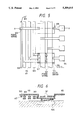
- FIG. 5 is a top plan view showing a relation between a clock wiring and a power wiring of the present invention.
- FIG. 6 is a section taken from FIG. 5;
- FIG. 7 is a circuit diagram showing an equivalent circuit showing the clock wiring of the present invention.
- FIG. 8 is a circuit diagram showing a modification of a dummy gate of FIG. 7.
- FIG. 9 is a circuit diagram showing a modification of a buffer of FIG. 7.
- FIG. 1 presents a top plan view of the LSI
- FIG. 2 is a clock diagram.
- an LSI 101 is constructed to include macro cells 102 having logical function and a random logical circuit 103.
- a transfer of signals between the LSI 101 and the outside is carried out through bonding pads 104 and an I/O area 105.
- a clock to be fed to the macro cell 102 or the random logical circuit 103 is transferred in the following manner.
- the clock is inputted from the outside through the bonding pad 104 and the I/O area 105 and has its waveform shaped by a clock pulse generator 106 until it is inputted to a clock driver A 107.
- the clock outputted from the clock driver A 107 is inputted through a clock wiring AB 110 to several or ten and several clock drivers B 108.
- the clock outputted from the clock driver B 108 is inputted through a clock wiring BC 111 and several to ten and several clock drivers C 109.
- Those clock drivers A 110 and B 108 are placed just below or in the vicinity of a power line since they may become sources of noise.
- the clock outputted from the aforementioned clock driver C 109 is inputted, as shown in FIG. 2, through a clock wiring CD 114 to a several to ten and several clock drivers D 112.
- the clock outputted from the clock driver D 112 is inputted through a clock wiring DE 115 to the clock terminals CLK of several to ten and several FFs 113.
- the clock terminal CLK of the FF is shown only for the uppermost FF in FIG. 2, but all the lower FFs likewise have their clock terminals CLK.
- the shield clock wiring of the present invention can be applied to all or a portion of the clock wiring AB 110, clock wiring BC 111, clock wiring CD 114 and clock wiring DE 115 thus far described.
- the shield clock wiring can be applied to only the clock wiring AB 110, for example.
- FIGS. 3 and 4 are perspective views showing embodiments of different structures, in which the present invention is applied to the clock wiring AB 110.
- the numeral 110 appearing in FIG. 3 designates the clock wiring AB, and shield clock wiring 303 is laid adjacent to the righthand and lefthand sides of the clock wiring AB 110.
- both the clock wiring AB 110 and the shield clock wiring 303 have their line resistances reduced by connecting two upper and lower conductors in parallel.
- a clock outputted from the pulse generator 106 acting as a drive source for driving the clock wiring AB 110 is inputted through the clock driver A 107 to the clock wiring AB 110 and the shield clock wiring 303.
- the clock driver A 107 is constructed to include a clock buffer 301 for driving the clock wiring AB 110 and a shield clock buffer 302 for driving the shield clock wiring 303.
- the individual buffers 301 and 302 are provided for isolating the individual wiring lines electrically and for equalizing the skews of the FFs. If the design should allow, direct connections not through any buffer could be achieved.
- reference numeral 304 appearing in FIG. 4 designates a signal wiring which intersect the clock wiring and which is connected with a gate 305 or the like.
- the clock wiring AB 110 is shielded by the shield clock wiring 303 to reduce its capacity with a power line or signal line (although not shown) connected adjacent to and in parallel with the clock wiring AB 110.
- a capacity is newly established between the clock wiring AB 110 and the shield clock wiring 303.
- the clock wiring AB 110 and the shield clock wiring 303 are fed with clocks in phase by the clock pulse generator 106 so that the clock signals of the two wiring lines operate at substantially equal rise/fall times to cancel the aforementioned newly established capacity.
- the capacity, as viewed from the clock buffer 301 is reduced to reduce the delay time of the buffer and the delay in the wiring resistance.
- the value of the capacity, as viewed from the clock wiring AB 110 can be fixed by the shield clock wiring 303 to reduce the dispersions in the delay between the individual clock wiring lines and in the rise/fall times.
- the delay dispersion and the rise/fall time delay can be further reduced by equalizing the lengths of the clock wiring lines AB 110 of the present embodiment.
- all the clock wiring lines AB 110 are arranged to have an equal length, as shown in FIG. 1.
- the clock wiring lines BC 111 are also equalized in length, although not shown in detail.
- FIG. 3 shows the embodiment, in which the shield clock wiring lines are laid at the two sides of the clock wiring. In case, however, the signal lines and the power lines are present over and below the clock wiring, the shield clock wiring lines are laid over and below the same.
- FIG. 4 shows the embodiment, in which the shield clock wiring line 303 is arranged between the upper signal wiring lines 304 in addition to the righthand and lefthand shield clock wiring lines 303 since the signal wiring 304 runs over the clock wiring AB 110.
- the shield clock wiring lines can be laid over and/or below and/or at the righthand and/or lefthand of the clock wiring AB 110.
- the shield clock wiring need not be laid for the whole length of the clock wiring line, but a predetermined effect could be obtained if the shield clock wiring is arranged in a partial region.
- the shield clock wiring need not be always formed for the signal wiring or power wiring. Even if another signal wiring 304 or power wiring (although not shown) runs thereabove or therebelow, as shown in FIG. 3, the shield clock wiring between the clock wiring AB 110 and the signal wiring 304 can be omitted if the capacity inbetween is low within an allowable range.
- the shield clock wiring in other directions can be omitted by laying it only in a direction to cause the shielding effect.
- the shield clock wiring lines of the present invention may be laid in different phases.
- the capacity of the shield clock wiring can be reduced by making the gap between the shield clock wiring lines in different phases wider than that between the clock wiring and the shield clock wiring.
- the gap between the individual wiring lines can be not only effective for the clock wiring lines of multiple phases but also applied to other portions.
- the external capacity of the shield clock wiring can be reduced, for example, by making the gap between the shield clock wiring and either the signal line adjacent thereto or the power wiring wider than that between the clock wiring and the shield clock wiring.
- FIG. 5 is a top plan view showing a portion of the present embodiment
- FIG. 6 is a section taken along line A--A of FIG. 5.
- FIG. 5 shows the positional relations between the individual wiring lines conceptionally but not schematically.
- a component such as an insulating layer having no direct relation to the description of the wiring structure is not shown.
- an I/O cell 504 is energized as a matter of fact by a power wiring 501, but their connection is not shown.
- the clock wiring AB 110 (carrying a ⁇ 1 clock signal) and the shield clock wiring 303 are laid adjacent to the I/O cell 504.
- a signal wiring 503 for connecting the I/O cell 504 and the inside of the LSI runs over the clock wiring AB 110 and the shield clock wiring 303.
- the clock wiring AB 110 can have its capacity easily reduced and can be easily arranged partly because the clock wiring AB 110 and the shield clock wiring 303 are present adjacent to the power wiring 501 and partly because the number of crossing signal wiring lines 503 is small.
- FIG. 5 Also illustrated in FIG. 5 is a second ⁇ 2 clock signal in clock wiring 110', otherwise the same as that 110.
- the present invention is exemplified by arranging the clock driver 106 just below the power line 501, i.e., the power ring and by forming the clock wiring AB 110 and the shield clock wiring 303 over a common layer.
- the shield clock wiring 303 adjacent to the power wiring 501 can be omitted although the capacity of the clock wiring AB 110 is increased more or less.
- the power wiring 501 has not a fluctuating potential as the signal wiring but a fixed potential so that the dispersion in the capacity between the clock wiring AB 110 and the power wiring 501 is reduced.
- the dispersion in the capacity can be reduced not by laying the shield clock wiring newly but by using the power wiring 501 as a shield.
- FIG. 7 An equivalent of the clock wiring of the present invention thus far described is shown in FIG. 7.
- the clock wiring AB 110 and the shield clock wiring 303 are illustrated in a distribution constant of a resistor R and a capacitor C.
- the capacitor C as expressed here, contains a capacity or the like, which is owned by a signal wiring running across or in parallel with the clock wiring AB 110 and the shield clock wiring 303.
- the clock buffer 301 drives the clock driver B 108 through the clock wiring AB 110.
- a dummy gate 701 for summing the capacities may be connected with the terminal or midway of the shield clock wiring 303 which is connected with the shield clock buffer 302.
- a terminal resistor 801 may be connected, as shown in FIG. 8.
- a capacitor, a diode, a transistor and so on may be added, although not shown. If unnecessary, the circuit may be opened without adding those elements.
- the type of the buffers 301 and 302 in the clock driver A 107 should not be limited to the use of a MOS transistor 702, as shown in FIG. 7, but the circuit may include a bipolar transistor or a combination of the MOS transistor 702 and a bipolar transistor 901, as shown in FIG. 9.
- the rise/fall times of the clock may be equivalently accelerated, if necessary, by changing the circuit type of the shield clock buffer 302 or by making the driving force stronger than that of the clock buffer 301.
- the rise/fall times of the clock may be equivalently accelerated by adding an additional function to the clock driver or inserting a delay element to delay the clock buffer relative to the shield clock buffer thereby to shift the phase.
- our invention has been described hereinbefore mainly in case it is applied to the clock wiring of the LSI backgrounding the field of application thereof, it should not be applied to the application.
- the present invention can be applied to a semiconductor integrated circuit device or printed wiring other than the LSI so that it can be widely applied to a technology using the clock wiring.
- the shield clock wiring is laid wholly or partially of the surrounding of the clock wiring to make the clock wiring and the shield clock wiring substantially in phase so that the capacity of the clock wiring can be reduced.
- the capacities between the individual clock wiring lines are equalized to reduce the delay time and rise/fall times of the clock so that the clock skew can be reduced.
Abstract
Description
Claims (10)
Applications Claiming Priority (2)
| Application Number | Priority Date | Filing Date | Title |
|---|---|---|---|
| JP3298900A JPH05136125A (en) | 1991-11-14 | 1991-11-14 | Clock wiring and semiconductor integrated circuit device having clock wiring |
| JP3-298900 | 1991-11-14 |
Publications (1)
| Publication Number | Publication Date |
|---|---|
| US5309015A true US5309015A (en) | 1994-05-03 |
Family
ID=17865616
Family Applications (1)
| Application Number | Title | Priority Date | Filing Date |
|---|---|---|---|
| US07/966,801 Expired - Fee Related US5309015A (en) | 1991-11-14 | 1992-10-26 | Clock wiring and semiconductor integrated circuit device having the same |
Country Status (3)
| Country | Link |
|---|---|
| US (1) | US5309015A (en) |
| JP (1) | JPH05136125A (en) |
| KR (1) | KR930011320A (en) |
Cited By (48)
| Publication number | Priority date | Publication date | Assignee | Title |
|---|---|---|---|---|
| US5442225A (en) * | 1993-08-13 | 1995-08-15 | Lsi Logic Corporation | Integrated circuit having interconnects with ringing suppressing elements |
| US5585664A (en) * | 1993-12-28 | 1996-12-17 | Kabushiki Kaisha Toshiba | Semiconductor integrated circuit device |
| US5625207A (en) * | 1992-10-09 | 1997-04-29 | Elsa Elektroniska Systems And Applications Ab | Semiconductor component with conductors at different levels |
| WO1997018591A1 (en) * | 1995-11-14 | 1997-05-22 | In-Chip | Integrated circuit cell architecture and routing scheme |
| US5671173A (en) * | 1994-06-10 | 1997-09-23 | Matsushita Electric Industrial Co., Ltd. | Semiconductor integrated circuit device with oblique metallization lines over memory bit and word lines |
| US5783846A (en) * | 1995-09-22 | 1998-07-21 | Hughes Electronics Corporation | Digital circuit with transistor geometry and channel stops providing camouflage against reverse engineering |
| US5841157A (en) * | 1996-07-23 | 1998-11-24 | Mitsubishi Electric Semiconductor Software Co., Ltd. | Semiconductor integrated circuit including a high density cell |
| US5866933A (en) * | 1992-07-31 | 1999-02-02 | Hughes Electronics Corporation | Integrated circuit security system and method with implanted interconnections |
| US5869852A (en) * | 1997-04-08 | 1999-02-09 | Mitsubishi Denki Kabushiki Kaisha | Semiconductor integrated circuit and semiconductor integrated circuit having layout designed by cell base system |
| US5883433A (en) * | 1995-04-24 | 1999-03-16 | Nec Corporation | Semiconductor device having a critical path wiring |
| US5892250A (en) * | 1996-01-30 | 1999-04-06 | Nec Corporation | Semiconductor integrated circuit chip |
| US5973375A (en) * | 1997-06-06 | 1999-10-26 | Hughes Electronics Corporation | Camouflaged circuit structure with step implants |
| US5994765A (en) * | 1996-07-01 | 1999-11-30 | Sun Microsystems, Inc. | Clock distribution network with efficient shielding |
| US6081005A (en) * | 1997-05-26 | 2000-06-27 | Oki Electric Industry Co., Ltd. | Semiconductor integrated circuit |
| US6091090A (en) * | 1997-09-19 | 2000-07-18 | In-Chip Systems, Inc. | Power and signal routing technique for gate array design |
| US6133621A (en) * | 1998-10-15 | 2000-10-17 | Stmicroelectronics S.R.L. | Integrated shielded electric connection |
| US6242767B1 (en) * | 1997-11-10 | 2001-06-05 | Lightspeed Semiconductor Corp. | Asic routing architecture |
| US6255675B1 (en) * | 1998-07-10 | 2001-07-03 | Xilinx, Inc. | Programmable capacitor for an integrated circuit |
| US6331719B2 (en) * | 1995-05-25 | 2001-12-18 | Mitsubishi Denki Kabushiki Kaisha | Semiconductor device for reducing effects of noise on an internal circuit |
| US6331733B1 (en) * | 1999-08-10 | 2001-12-18 | Easic Corporation | Semiconductor device |
| US20020096776A1 (en) * | 2001-01-24 | 2002-07-25 | Hrl Laboratories, Llc | Integrated circuits protected against reverse engineering and method for fabricating the same using an apparent metal contact line terminating on field oxide |
| US20020173131A1 (en) * | 2000-10-25 | 2002-11-21 | Clark William M. | Implanted hidden interconnections in a semiconductor device for preventing reverse engineering |
| US6570195B2 (en) | 1997-12-02 | 2003-05-27 | Nurlogic Design, Inc. | Power/ground metallization routing in a semiconductor device |
| US20030155587A1 (en) * | 2002-01-18 | 2003-08-21 | Lyle Smith | ASIC routing architecture |
| US6613611B1 (en) | 2000-12-22 | 2003-09-02 | Lightspeed Semiconductor Corporation | ASIC routing architecture with variable number of custom masks |
| US20030197249A1 (en) * | 2002-04-17 | 2003-10-23 | Thomas Doderer | Contactable integrated circuit and method of producing such a circuit |
| US20030221174A1 (en) * | 2002-05-24 | 2003-11-27 | Trivedi Pradeep R. | Clock skew reduction using active shields |
| US6667245B2 (en) | 1999-11-10 | 2003-12-23 | Hrl Laboratories, Llc | CMOS-compatible MEM switches and method of making |
| US20040012067A1 (en) * | 2001-06-15 | 2004-01-22 | Hrl Laboratories, Llc | Programmable connector/isolator and double polysilicon layer CMOS process with buried contact using the same |
| US20040032002A1 (en) * | 2002-08-13 | 2004-02-19 | Sun Microsystems, Inc. | Active pulsed scheme for driving long interconnects |
| US20040061186A1 (en) * | 2002-09-27 | 2004-04-01 | Lap-Wai Chow | Conductive channel pseudo block process and circuit to inhibit reverse engineering |
| US20040068709A1 (en) * | 2002-10-08 | 2004-04-08 | Sun Microsystems, Inc. | Use of coupling capacitance to balance skew in a network |
| US6740942B2 (en) | 2001-06-15 | 2004-05-25 | Hrl Laboratories, Llc. | Permanently on transistor implemented using a double polysilicon layer CMOS process with buried contact |
| US20040099912A1 (en) * | 2002-11-22 | 2004-05-27 | Hrl Laboratories, Llc. | Use of silicon block process step to camouflage a false transistor |
| US20040144998A1 (en) * | 2002-12-13 | 2004-07-29 | Lap-Wai Chow | Integrated circuit modification using well implants |
| US6781238B2 (en) * | 2000-04-03 | 2004-08-24 | Nec Corporation | Semiconductor device and method of fabricating the same |
| US6791191B2 (en) | 2001-01-24 | 2004-09-14 | Hrl Laboratories, Llc | Integrated circuits protected against reverse engineering and method for fabricating the same using vias without metal terminations |
| US6897535B2 (en) | 2002-05-14 | 2005-05-24 | Hrl Laboratories, Llc | Integrated circuit with reverse engineering protection |
| US20050230787A1 (en) * | 2004-04-19 | 2005-10-20 | Hrl Laboratories, Llc. | Covert transformation of transistor properties as a circuit protection method |
| US6963510B1 (en) | 1998-07-10 | 2005-11-08 | Xilinx, Inc. | Programmable capacitor and method of operating same |
| US20050253249A1 (en) * | 2003-10-20 | 2005-11-17 | Industrial Technology Research Institute | Multi-layered complementary wire structure and manufacturing method thereof |
| US7242063B1 (en) | 2004-06-29 | 2007-07-10 | Hrl Laboratories, Llc | Symmetric non-intrusive and covert technique to render a transistor permanently non-operable |
| US20080079082A1 (en) * | 2006-09-28 | 2008-04-03 | Hrl Laboratories, Llc | Programmable connection and isolation of active regions in an integrated circuit using ambiguous features to confuse a reverse engineer |
| US20080184179A1 (en) * | 2007-01-30 | 2008-07-31 | Fujitsu Limited | Integrated circuit designing device, integrated circuit designing method, and integrated circuit designing program |
| US20100308458A1 (en) * | 2000-12-18 | 2010-12-09 | Renesas Electronics Corporation | Semiconductor integrated circuit device |
| US9576101B2 (en) | 2015-03-02 | 2017-02-21 | Freescale Semiconductor, Inc. | Configurable cell design using capacitive coupling for enhanced timing closure |
| US20190179362A1 (en) * | 2017-12-12 | 2019-06-13 | Dirk J. Robinson | Low-power multi-phase clock distribution on silicon |
| EP3586361A4 (en) * | 2017-03-31 | 2020-04-08 | Huawei Technologies Co., Ltd. | Shield structure for a low crosstalk single ended clock distribution circuit |
Families Citing this family (6)
| Publication number | Priority date | Publication date | Assignee | Title |
|---|---|---|---|---|
| EP0977263A3 (en) * | 1998-07-31 | 2002-07-10 | STMicroelectronics, Inc. | Apparatus and method for reducing propagation delay in a conductor |
| KR100346056B1 (en) * | 1999-12-17 | 2002-07-24 | 한국조폐공사 | A process for the preparation of a fiber containing uv fluorescent pigment |
| JP2007335888A (en) * | 2000-12-18 | 2007-12-27 | Renesas Technology Corp | Semiconductor integrated circuit device |
| JP3767520B2 (en) | 2002-06-12 | 2006-04-19 | 日本電気株式会社 | Integrated circuit device |
| JP2013231977A (en) * | 2013-06-04 | 2013-11-14 | Semiconductor Energy Lab Co Ltd | Display device |
| US9349682B2 (en) * | 2014-02-27 | 2016-05-24 | Mediatek Inc. | Semiconductor chip and semiconductor chip package each having signal paths that balance clock skews |
Citations (5)
| Publication number | Priority date | Publication date | Assignee | Title |
|---|---|---|---|---|
| JPS59144171A (en) * | 1983-02-07 | 1984-08-18 | Hitachi Ltd | Semiconductor integrated circuit device |
| US4514749A (en) * | 1983-01-18 | 1985-04-30 | At&T Bell Laboratories | VLSI Chip with ground shielding |
| US4958222A (en) * | 1988-06-10 | 1990-09-18 | Kabushiki Kaisha Toshiba | Semiconductor integrated circuit device |
| JPH03224261A (en) * | 1990-01-30 | 1991-10-03 | Fujitsu Ltd | Semiconductor integrated circuit device |
| US5160997A (en) * | 1988-08-12 | 1992-11-03 | Sanyo Electric Co., Ltd. | Semiconductor integrated circuit with shield electrodes for protecting the interconnection lines from undesirable radiation |
-
1991
- 1991-11-14 JP JP3298900A patent/JPH05136125A/en active Pending
-
1992
- 1992-10-26 US US07/966,801 patent/US5309015A/en not_active Expired - Fee Related
- 1992-10-28 KR KR1019920019924A patent/KR930011320A/en not_active Application Discontinuation
Patent Citations (5)
| Publication number | Priority date | Publication date | Assignee | Title |
|---|---|---|---|---|
| US4514749A (en) * | 1983-01-18 | 1985-04-30 | At&T Bell Laboratories | VLSI Chip with ground shielding |
| JPS59144171A (en) * | 1983-02-07 | 1984-08-18 | Hitachi Ltd | Semiconductor integrated circuit device |
| US4958222A (en) * | 1988-06-10 | 1990-09-18 | Kabushiki Kaisha Toshiba | Semiconductor integrated circuit device |
| US5160997A (en) * | 1988-08-12 | 1992-11-03 | Sanyo Electric Co., Ltd. | Semiconductor integrated circuit with shield electrodes for protecting the interconnection lines from undesirable radiation |
| JPH03224261A (en) * | 1990-01-30 | 1991-10-03 | Fujitsu Ltd | Semiconductor integrated circuit device |
Non-Patent Citations (2)
| Title |
|---|
| Yamagishi, Mikio, et al. "A Two-Chip CMOS 64b Mainframe Processor Chipset," IEEE 1991 Custom Integrated Circuits Conference, pp. 15.4.1 through 15.4.4. (Provided in English). |
| Yamagishi, Mikio, et al. A Two Chip CMOS 64b Mainframe Processor Chipset, IEEE 1991 Custom Integrated Circuits Conference, pp. 15.4.1 through 15.4.4. (Provided in English). * |
Cited By (91)
| Publication number | Priority date | Publication date | Assignee | Title |
|---|---|---|---|---|
| US6613661B1 (en) | 1992-07-31 | 2003-09-02 | Hughes Electronics Corporation | Process for fabricating secure integrated circuit |
| US6294816B1 (en) | 1992-07-31 | 2001-09-25 | Hughes Electronics Corporation | Secure integrated circuit |
| US5866933A (en) * | 1992-07-31 | 1999-02-02 | Hughes Electronics Corporation | Integrated circuit security system and method with implanted interconnections |
| US5625207A (en) * | 1992-10-09 | 1997-04-29 | Elsa Elektroniska Systems And Applications Ab | Semiconductor component with conductors at different levels |
| US5442225A (en) * | 1993-08-13 | 1995-08-15 | Lsi Logic Corporation | Integrated circuit having interconnects with ringing suppressing elements |
| US5585664A (en) * | 1993-12-28 | 1996-12-17 | Kabushiki Kaisha Toshiba | Semiconductor integrated circuit device |
| US5671173A (en) * | 1994-06-10 | 1997-09-23 | Matsushita Electric Industrial Co., Ltd. | Semiconductor integrated circuit device with oblique metallization lines over memory bit and word lines |
| US5883433A (en) * | 1995-04-24 | 1999-03-16 | Nec Corporation | Semiconductor device having a critical path wiring |
| US5990001A (en) * | 1995-04-24 | 1999-11-23 | Nec Corporation | Method of forming a semiconductor device having a critical path wiring |
| US6331719B2 (en) * | 1995-05-25 | 2001-12-18 | Mitsubishi Denki Kabushiki Kaisha | Semiconductor device for reducing effects of noise on an internal circuit |
| US5930663A (en) * | 1995-09-22 | 1999-07-27 | Hughes Electronics Corporation | Digital circuit with transistor geometry and channel stops providing camouflage against reverse engineering |
| US6064110A (en) * | 1995-09-22 | 2000-05-16 | Hughes Electronics Corporation | Digital circuit with transistor geometry and channel stops providing camouflage against reverse engineering |
| US5783846A (en) * | 1995-09-22 | 1998-07-21 | Hughes Electronics Corporation | Digital circuit with transistor geometry and channel stops providing camouflage against reverse engineering |
| WO1997018591A1 (en) * | 1995-11-14 | 1997-05-22 | In-Chip | Integrated circuit cell architecture and routing scheme |
| US5723883A (en) * | 1995-11-14 | 1998-03-03 | In-Chip | Gate array cell architecture and routing scheme |
| US5892250A (en) * | 1996-01-30 | 1999-04-06 | Nec Corporation | Semiconductor integrated circuit chip |
| US5994765A (en) * | 1996-07-01 | 1999-11-30 | Sun Microsystems, Inc. | Clock distribution network with efficient shielding |
| US6081022A (en) * | 1996-07-01 | 2000-06-27 | Sun Microsystems, Inc. | Clock distribution network with efficient shielding |
| US5841157A (en) * | 1996-07-23 | 1998-11-24 | Mitsubishi Electric Semiconductor Software Co., Ltd. | Semiconductor integrated circuit including a high density cell |
| US5869852A (en) * | 1997-04-08 | 1999-02-09 | Mitsubishi Denki Kabushiki Kaisha | Semiconductor integrated circuit and semiconductor integrated circuit having layout designed by cell base system |
| US6081005A (en) * | 1997-05-26 | 2000-06-27 | Oki Electric Industry Co., Ltd. | Semiconductor integrated circuit |
| US5973375A (en) * | 1997-06-06 | 1999-10-26 | Hughes Electronics Corporation | Camouflaged circuit structure with step implants |
| US6091090A (en) * | 1997-09-19 | 2000-07-18 | In-Chip Systems, Inc. | Power and signal routing technique for gate array design |
| US6242767B1 (en) * | 1997-11-10 | 2001-06-05 | Lightspeed Semiconductor Corp. | Asic routing architecture |
| US6570195B2 (en) | 1997-12-02 | 2003-05-27 | Nurlogic Design, Inc. | Power/ground metallization routing in a semiconductor device |
| US6255675B1 (en) * | 1998-07-10 | 2001-07-03 | Xilinx, Inc. | Programmable capacitor for an integrated circuit |
| US6963510B1 (en) | 1998-07-10 | 2005-11-08 | Xilinx, Inc. | Programmable capacitor and method of operating same |
| US6133621A (en) * | 1998-10-15 | 2000-10-17 | Stmicroelectronics S.R.L. | Integrated shielded electric connection |
| US6476493B2 (en) | 1999-08-10 | 2002-11-05 | Easic Corp | Semiconductor device |
| US6331733B1 (en) * | 1999-08-10 | 2001-12-18 | Easic Corporation | Semiconductor device |
| US6667245B2 (en) | 1999-11-10 | 2003-12-23 | Hrl Laboratories, Llc | CMOS-compatible MEM switches and method of making |
| US6781238B2 (en) * | 2000-04-03 | 2004-08-24 | Nec Corporation | Semiconductor device and method of fabricating the same |
| US6815816B1 (en) | 2000-10-25 | 2004-11-09 | Hrl Laboratories, Llc | Implanted hidden interconnections in a semiconductor device for preventing reverse engineering |
| US20020173131A1 (en) * | 2000-10-25 | 2002-11-21 | Clark William M. | Implanted hidden interconnections in a semiconductor device for preventing reverse engineering |
| US7166515B2 (en) | 2000-10-25 | 2007-01-23 | Hrl Laboratories, Llc | Implanted hidden interconnections in a semiconductor device for preventing reverse engineering |
| US7982314B2 (en) | 2000-12-18 | 2011-07-19 | Renesas Electronics Corporation | Semiconductor integrated circuit device |
| US20100308458A1 (en) * | 2000-12-18 | 2010-12-09 | Renesas Electronics Corporation | Semiconductor integrated circuit device |
| US6613611B1 (en) | 2000-12-22 | 2003-09-02 | Lightspeed Semiconductor Corporation | ASIC routing architecture with variable number of custom masks |
| US20020096776A1 (en) * | 2001-01-24 | 2002-07-25 | Hrl Laboratories, Llc | Integrated circuits protected against reverse engineering and method for fabricating the same using an apparent metal contact line terminating on field oxide |
| US6791191B2 (en) | 2001-01-24 | 2004-09-14 | Hrl Laboratories, Llc | Integrated circuits protected against reverse engineering and method for fabricating the same using vias without metal terminations |
| US7294935B2 (en) | 2001-01-24 | 2007-11-13 | Hrl Laboratories, Llc | Integrated circuits protected against reverse engineering and method for fabricating the same using an apparent metal contact line terminating on field oxide |
| US6774413B2 (en) | 2001-06-15 | 2004-08-10 | Hrl Laboratories, Llc | Integrated circuit structure with programmable connector/isolator |
| US6893916B2 (en) | 2001-06-15 | 2005-05-17 | Hrl Laboratories, Llc | Programmable connector/isolator and double polysilicon layer CMOS process with buried contact using the same |
| US20040012067A1 (en) * | 2001-06-15 | 2004-01-22 | Hrl Laboratories, Llc | Programmable connector/isolator and double polysilicon layer CMOS process with buried contact using the same |
| US6740942B2 (en) | 2001-06-15 | 2004-05-25 | Hrl Laboratories, Llc. | Permanently on transistor implemented using a double polysilicon layer CMOS process with buried contact |
| US6919600B2 (en) | 2001-06-15 | 2005-07-19 | Hrl Laboratories, Llc | Permanently on transistor implemented using a double polysilicon layer CMOS process with buried contact |
| US20040164361A1 (en) * | 2001-06-15 | 2004-08-26 | Hrl Laboratories, Llc | Permanently on transistor implemented using a double polysilicon layer CMOS process with buried contact |
| US20030155587A1 (en) * | 2002-01-18 | 2003-08-21 | Lyle Smith | ASIC routing architecture |
| US6885043B2 (en) | 2002-01-18 | 2005-04-26 | Lightspeed Semiconductor Corporation | ASIC routing architecture |
| US20030197249A1 (en) * | 2002-04-17 | 2003-10-23 | Thomas Doderer | Contactable integrated circuit and method of producing such a circuit |
| US6897535B2 (en) | 2002-05-14 | 2005-05-24 | Hrl Laboratories, Llc | Integrated circuit with reverse engineering protection |
| US7008873B2 (en) | 2002-05-14 | 2006-03-07 | Hrl Laboratories, Llc | Integrated circuit with reverse engineering protection |
| US20050161748A1 (en) * | 2002-05-14 | 2005-07-28 | Hrl Laboratories, Llc | Integrated circuit with reverse engineering protection |
| US6708314B2 (en) * | 2002-05-24 | 2004-03-16 | Sun Microsystems, Inc. | Clock skew reduction using active shields |
| US20030221174A1 (en) * | 2002-05-24 | 2003-11-27 | Trivedi Pradeep R. | Clock skew reduction using active shields |
| US20040032002A1 (en) * | 2002-08-13 | 2004-02-19 | Sun Microsystems, Inc. | Active pulsed scheme for driving long interconnects |
| US6828852B2 (en) * | 2002-08-13 | 2004-12-07 | Sun Microsystems, Inc. | Active pulsed scheme for driving long interconnects |
| US20040061186A1 (en) * | 2002-09-27 | 2004-04-01 | Lap-Wai Chow | Conductive channel pseudo block process and circuit to inhibit reverse engineering |
| US7888213B2 (en) | 2002-09-27 | 2011-02-15 | Hrl Laboratories, Llc | Conductive channel pseudo block process and circuit to inhibit reverse engineering |
| US8258583B1 (en) | 2002-09-27 | 2012-09-04 | Hrl Laboratories, Llc | Conductive channel pseudo block process and circuit to inhibit reverse engineering |
| US20060157803A1 (en) * | 2002-09-27 | 2006-07-20 | Hrl Laboratories, Llc | Conductive channel pseudo block process and circuit to inhibit reverse engineering |
| US20040068709A1 (en) * | 2002-10-08 | 2004-04-08 | Sun Microsystems, Inc. | Use of coupling capacitance to balance skew in a network |
| US6789245B2 (en) * | 2002-10-08 | 2004-09-07 | Sun Microsystems, Inc. | Use of coupling capacitance to balance skew in a network |
| US20040099912A1 (en) * | 2002-11-22 | 2004-05-27 | Hrl Laboratories, Llc. | Use of silicon block process step to camouflage a false transistor |
| US8679908B1 (en) | 2002-11-22 | 2014-03-25 | Hrl Laboratories, Llc | Use of silicide block process to camouflage a false transistor |
| US20070243675A1 (en) * | 2002-11-22 | 2007-10-18 | Hrl Laboratories, Llc | Use of silicon block process step to camouflage a false transistor |
| US6979606B2 (en) | 2002-11-22 | 2005-12-27 | Hrl Laboratories, Llc | Use of silicon block process step to camouflage a false transistor |
| US7344932B2 (en) | 2002-11-22 | 2008-03-18 | Hrl Laboratories, Llc | Use of silicon block process step to camouflage a false transistor |
| US7514755B2 (en) | 2002-12-13 | 2009-04-07 | Hrl Laboratories Llc | Integrated circuit modification using well implants |
| US8524553B2 (en) | 2002-12-13 | 2013-09-03 | Hrl Laboratories, Llc | Integrated circuit modification using well implants |
| US20040144998A1 (en) * | 2002-12-13 | 2004-07-29 | Lap-Wai Chow | Integrated circuit modification using well implants |
| US20050253249A1 (en) * | 2003-10-20 | 2005-11-17 | Industrial Technology Research Institute | Multi-layered complementary wire structure and manufacturing method thereof |
| US7161226B2 (en) * | 2003-10-20 | 2007-01-09 | Industrial Technology Research Institute | Multi-layered complementary wire structure and manufacturing method thereof |
| US7541266B2 (en) | 2004-04-19 | 2009-06-02 | Hrl Laboratories, Llc | Covert transformation of transistor properties as a circuit protection method |
| US20070224750A1 (en) * | 2004-04-19 | 2007-09-27 | Hrl Laboratories, Llc | Covert transformation of transistor properties as a circuit protection method |
| US20050230787A1 (en) * | 2004-04-19 | 2005-10-20 | Hrl Laboratories, Llc. | Covert transformation of transistor properties as a circuit protection method |
| US7217977B2 (en) | 2004-04-19 | 2007-05-15 | Hrl Laboratories, Llc | Covert transformation of transistor properties as a circuit protection method |
| US7242063B1 (en) | 2004-06-29 | 2007-07-10 | Hrl Laboratories, Llc | Symmetric non-intrusive and covert technique to render a transistor permanently non-operable |
| US8049281B1 (en) | 2004-06-29 | 2011-11-01 | Hrl Laboratories, Llc | Symmetric non-intrusive and covert technique to render a transistor permanently non-operable |
| US7935603B1 (en) | 2004-06-29 | 2011-05-03 | Hrl Laboratories, Llc | Symmetric non-intrusive and covert technique to render a transistor permanently non-operable |
| US8564073B1 (en) | 2006-09-28 | 2013-10-22 | Hrl Laboratories, Llc | Programmable connection and isolation of active regions in an integrated circuit using ambiguous features to confuse a reverse engineer |
| US8168487B2 (en) | 2006-09-28 | 2012-05-01 | Hrl Laboratories, Llc | Programmable connection and isolation of active regions in an integrated circuit using ambiguous features to confuse a reverse engineer |
| US20080079082A1 (en) * | 2006-09-28 | 2008-04-03 | Hrl Laboratories, Llc | Programmable connection and isolation of active regions in an integrated circuit using ambiguous features to confuse a reverse engineer |
| US20080184179A1 (en) * | 2007-01-30 | 2008-07-31 | Fujitsu Limited | Integrated circuit designing device, integrated circuit designing method, and integrated circuit designing program |
| US7757192B2 (en) * | 2007-01-30 | 2010-07-13 | Fujitsu Limited | Integrated circuit designing device, integrated circuit designing method, and integrated circuit designing program |
| US9576101B2 (en) | 2015-03-02 | 2017-02-21 | Freescale Semiconductor, Inc. | Configurable cell design using capacitive coupling for enhanced timing closure |
| EP3586361A4 (en) * | 2017-03-31 | 2020-04-08 | Huawei Technologies Co., Ltd. | Shield structure for a low crosstalk single ended clock distribution circuit |
| US10939541B2 (en) | 2017-03-31 | 2021-03-02 | Huawei Technologies Co., Ltd. | Shield structure for a low crosstalk single ended clock distribution circuit |
| EP4060732A1 (en) * | 2017-03-31 | 2022-09-21 | Huawei Technologies Co., Ltd. | Shield structure for a low crosstalk single ended clock distribution circuit |
| US20190179362A1 (en) * | 2017-12-12 | 2019-06-13 | Dirk J. Robinson | Low-power multi-phase clock distribution on silicon |
| US10503203B2 (en) * | 2017-12-12 | 2019-12-10 | Advanced Micro Devices, Inc. | Low-power multi-phase clock distribution on silicon |
Also Published As
| Publication number | Publication date |
|---|---|
| KR930011320A (en) | 1993-06-24 |
| JPH05136125A (en) | 1993-06-01 |
Similar Documents
| Publication | Publication Date | Title |
|---|---|---|
| US5309015A (en) | Clock wiring and semiconductor integrated circuit device having the same | |
| JP3433731B2 (en) | I / O cell arrangement method and semiconductor device | |
| US6130484A (en) | Semiconductor device | |
| US5581109A (en) | Semiconductor device | |
| US6268643B1 (en) | Lead frame device for delivering electrical power to a semiconductor die | |
| JP3026387B2 (en) | Semiconductor integrated circuit | |
| JPH06244282A (en) | Semiconductor integrated circuit device | |
| JP2000269211A (en) | Semiconductor device | |
| JP3831593B2 (en) | Multi-chip module | |
| JP2011509043A (en) | Jitter reduction in semiconductor devices by controlling printed circuit board and package substrate stacking | |
| US6222278B1 (en) | Input-output circuit cell and semiconductor integrated circuit apparatus | |
| US11049830B2 (en) | Level shifting between interconnected chips having different voltage potentials | |
| EP0041844B1 (en) | Semiconductor integrated circuit devices | |
| US7280380B2 (en) | Semiconductor memory device and method of making design change to semiconductor chip | |
| JP2876963B2 (en) | Semiconductor device | |
| JPH08222602A (en) | Semiconductor device | |
| US5670802A (en) | Semiconductor device | |
| US20020130424A1 (en) | Semiconductor integrated circuit | |
| US5365406A (en) | Master-slice type semiconductor integrated circuit device | |
| JP2776551B2 (en) | Bus line type semiconductor memory device | |
| JPH0348455A (en) | Semiconductor device | |
| JP5277491B2 (en) | Semiconductor device | |
| US7550838B2 (en) | Semiconductor device | |
| JPH0265240A (en) | Semiconductor integrated device | |
| JPH02148860A (en) | Semiconductor device |
Legal Events
| Date | Code | Title | Description |
|---|---|---|---|
| AS | Assignment |
Owner name: HITACHI VLSI ENGINEERING CORP., JAPAN Free format text: ASSIGNMENT OF ASSIGNORS INTEREST;ASSIGNORS:KUWATA, MAKOTO;KITAMURA, NOBUAKI;REEL/FRAME:006766/0400 Effective date: 19921016 Owner name: HITACHI, LTD., JAPAN Free format text: ASSIGNMENT OF ASSIGNORS INTEREST;ASSIGNORS:KUWATA, MAKOTO;KITAMURA, NOBUAKI;REEL/FRAME:006766/0400 Effective date: 19921016 |
|
| FEPP | Fee payment procedure |
Free format text: PAYOR NUMBER ASSIGNED (ORIGINAL EVENT CODE: ASPN); ENTITY STATUS OF PATENT OWNER: LARGE ENTITY |
|
| FPAY | Fee payment |
Year of fee payment: 4 |
|
| REMI | Maintenance fee reminder mailed | ||
| LAPS | Lapse for failure to pay maintenance fees | ||
| STCH | Information on status: patent discontinuation |
Free format text: PATENT EXPIRED DUE TO NONPAYMENT OF MAINTENANCE FEES UNDER 37 CFR 1.362 |
|
| FP | Lapsed due to failure to pay maintenance fee |
Effective date: 20020503 |