US5306263A - Catheter - Google Patents
Catheter Download PDFInfo
- Publication number
- US5306263A US5306263A US07/877,288 US87728892A US5306263A US 5306263 A US5306263 A US 5306263A US 87728892 A US87728892 A US 87728892A US 5306263 A US5306263 A US 5306263A
- Authority
- US
- United States
- Prior art keywords
- catheter
- angle
- proximal end
- curved
- curve
- Prior art date
- Legal status (The legal status is an assumption and is not a legal conclusion. Google has not performed a legal analysis and makes no representation as to the accuracy of the status listed.)
- Expired - Lifetime
Links
Images


Classifications
-
- A—HUMAN NECESSITIES
- A61—MEDICAL OR VETERINARY SCIENCE; HYGIENE
- A61M—DEVICES FOR INTRODUCING MEDIA INTO, OR ONTO, THE BODY; DEVICES FOR TRANSDUCING BODY MEDIA OR FOR TAKING MEDIA FROM THE BODY; DEVICES FOR PRODUCING OR ENDING SLEEP OR STUPOR
- A61M25/00—Catheters; Hollow probes
- A61M25/0021—Catheters; Hollow probes characterised by the form of the tubing
- A61M25/0041—Catheters; Hollow probes characterised by the form of the tubing pre-formed, e.g. specially adapted to fit with the anatomy of body channels
Definitions
- This invention relates generally to catheters adapted to be inserted into the cardiovascular system of a living body and, more particularly, to an improved, preshaped catheter having an improved distal end portion for more precise location in the right coronary artery of the cardiovascular system.
- Catheters are often used in the performance of medical procedures such as coronary angiography for injecting dye, or the like, into the cardiovascular system for diagnosis; and angioplasty to widen the lumen of a coronary artery which has become at least partially blocked by a stenotic lesion causing an abnormal narrowing of the artery due to injury or disease.
- the distal end of the catheter is introduced into the aorta by way of the femoral artery.
- the proximal end of the catheter is then manipulated so its distal end is inserted into the lumen of a selected coronary artery branching off from the aorta.
- a typical angioplasty procedure would involve initially inserting a guiding catheter into the cardiovascular system in the above manner, followed by a dilating catheter, a laser catheter, an atherectomy catheter, or the like, which is guided through the guiding catheter until its distal end portion is positioned within the stenotic lesion in the coronary artery to reduce the blockage in the artery.
- a dilating catheter a laser catheter, an atherectomy catheter, or the like
- the most common catheter used in treatment of the right coronary artery is what is often referred to as a "Judkins" catheter which has a specially shaped distal end portion for facilitating insertion and engagement into the right coronary artery.
- a "Judkins” catheter which has a specially shaped distal end portion for facilitating insertion and engagement into the right coronary artery.
- the Judkins catheter requires a 180 degree rotation and adroit manipulation to selectively engage the right coronary artery.
- the catheter of the present invention includes an elongated, preformed tubular member having a first straight portion extending from the proximal end of the catheter and a distal end portion extending from the straight portion and bent in a unique manner to enable the distal end to be precisely located relative to the right coronary artery.
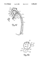
- FIGS. 1A and 1B are side and front views, respectively, of a portion of the catheter of the prior art
- FIG. 1C is a cross sectional view of a portion of a cardiovascular system with the catheter of FIGS. 1A and 1B inserted therein;
- FIG. 1D is an enlarged cross-sectional view taken along the line 1D--1D;
- FIGS. 2A-2D, 3A-3D, 4A-4D, 5A-D and 6A-D are views similar to FIGS. 1A-1D, respectively, but depicting alternate embodiments of the present invention.
- the reference numerical 10 refers, in general, to a well known prior art catheter, commonly referred to as a "Judkins" catheter.
- the catheter 10 is in the form of an elongated tubular member having a straight portion 12 (shown partially in FIGS. 1A and 1B) and a distal end portion.
- the distal end portion consists of a tertiary curved portion 14, a secondary curved portion 16, a primary curved portion 18, and a tip portion 20.
- the tertiary curved portion 14 extends from the straight portion 12 and is bent to form a curve of approximately 30 degrees.
- the secondary curved portion 16 extends from the tertiary curved portion 14 and is bent in the opposite direction to the tertiary curved portion 14 to form a curve of approximately 30 degrees.
- the primary curved portion 18 artery 30 and is connected to the heart (not shown). As better shown in FIG. 1D, the right coronary artery 28 and the left coronary artery 30 are normally angularly spaced approximately 120 degrees.
- the prior art Judkins' catheter 10 of FIGS. 1A and 1B is designed for use as a diagnostic catheter in the right coronary artery 28 but is also used as a guiding catheter for treatment of stenotic lesions, or the like.
- the catheter 10 is inserted into the system 22 and is manipulated so that, ideally, the tip portion 20 of the catheter 10 is positioned through the ostium 26 and into the lumen of the right coronary artery 28 and used to guide other catheters, such as balloon, laser or atherectomy catheters, or the like (not shown) into the right coronary artery 28.
- a relatively stiff wire is initially inserted into the catheter 10 to straighten it.
- the wire is withdrawn, causing the catheter to position itself along the wall of the ascending aorta 24b, 1 to 2 cm. above the ostium 27 of the left coronary artery 30.
- the tip portion 20 of the Judkins catheter 10 points away from the ostium 26 of the right coronary artery 28 and extends from the curved portion 16 and is bent to form a curve of approximately 90 degrees and the tip portion 20 extends from the curved portion 18.
- the curved portions 14 and 16 would have a radius of curvature of 10 and 5 centimeters ("cm.”), respectively, and the tip portion 20 would have a length of 1 cm.
- the catheter 10 is usually fabricated of a plastic material selected to exhibit flexibility and softness yet permit adequate "torque control" i.e., the ability to transmit twisting forces along its length so that it can be located and maneuvered precisely within a cardiovascular system by skilled manipulation of its proximal end, as will be described.
- FIGS. 1C and 1D A typical cardiovascular system is shown in FIGS. 1C and 1D and is referred to, in general, by the reference numeral 22.
- the system 22 includes an aorta 24 comprised of a descending aorta 24a, an ascending aorta 24b, and an aortic arch 24c which extends from the descending aorta 24a to the ascending aorta 24b over a curve of approximately 180 degrees.
- the ascending aorta 24b then branches through a right ostium 26 and a left ostium 27 into a right coronary artery 28 and a left coronary artery 30, respectively
- An aortic valve 32 extends between the right coronary artery 28 and the left coronary must be rotated 180 degrees. During this rotation, the catheter 10 will suddenly descend about 3 cm. until the tip portion 20 hopefully aligns with the ostium 26 of the right coronary artery 28 in a coaxial relationship as shown in FIG. 1C.
- the tip portion 20 is often misaligned with the ostium 26 of the right coronary artery 2 and is not located coaxially with the latter artery.
- an inner catheter such as a balloon catheter (not shown) is passed through the catheter 10
- the former often strikes the wall of the ascending aorta 24b or the right coronary artery 28 increasing the risk of damage.
- the catheter 10 does not provide support for other catheters or devices that are passed through the catheter 10. Due to the lack of support, when axial forces are exerted on the tip portion 20, such as when a dilation balloon is advanced, the tip portion 20 has a tendency to push back from the ostium 26 causing the tip portion 20 to dislodge from the lumen of the right coronary artery 28 and the balloon catheter to prolapse in the ascending aorta 24b.
- the catheter of the present invention is specifically designed to overcome the aforementioned deficiencies of the Judkins type catheter 10, and one embodiment of the catheter of the present invention is shown in general by the reference numeral 36 in FIGS. 2A-2D.
- the catheter 36 is in the form of an elongated, preformed tubular member having a straight portion 38 extending from the proximal end portion (not shown) of the catheter 36.
- the catheter 36 includes a distal end portion formed by a curved portion 40, a plurality of straight portions 42, 44, and 46, and a tip portion 48.
- the curved portion 40 extends from the straight portion 3 for approximately 200-240 degrees.
- the straight portion 42 extends from the curved portion 40 toward, and at an angle to, the straight portion 38.
- the straight portion 44 extends from, and at an angle to, the straight portion 42, and generally parallel to the straight portion 38.
- the straight portion 46 extends from, and at an angle to, the straight portion 44 and the tip portion 48 extends from, and at an angle to, the straight portion 46 and generally perpendicular to the straight portion 38.
- the curved portion 40 has a radius of curvature of approximately 5 cm. and the distance D1 between the tip portion 48 and the outer edge of the curved portion 40 is approximately 12.5 cm.
- the distance D2 between the straight portions 44 and 38 is approximately 2.5 cm.
- the straight portion 44 is approximately 1.5 cm. in length, and the straight portions 46 and 48 are each approximately 1.2 cm. in length.
- the angle between the straight portions 42 and 44 is between 20 degrees and 50 degrees, the angle between the straight portions 44 and 46 is between 10 degrees and 50 degrees, and the angle between the straight portion 46 and the tip portion 48 is between 10 degrees and 50 degrees. It is understood that these distances and angles represent only one possible configuration of the catheter 36.
- the length of straight portion 44 can be increased to other values within the scope of the invention and thus provide increased support as compared to the Judkins catheter.
- the aforementioned dimensions can vary substantially and depend extensively on the variance of human cardiovascular physiology.
- the curved portion 40 typically will have a radius of curvature of approximately 5 cm.
- the radius of curvature can vary from approximately 5 to 7 cm.
- the distance D1 can vary from approximately 6 to 16 cm.
- the distance D2 can vary from approximately 0.0 to 6 cm.
- the straight portions 46 and 48 can vary from 0.5 to 2 cm. in length.
- straight portion 38 extends in the same plane as the above described distal end portion.
- the catheter 36 can be fabricated of a material, such as plastic, which exhibits optimum flexibility and softness while permitting the transmission of twisting forces along its length by manipulation of its proximal end.
- the material is tubular, i.e. it has a continuous bore extending through its entire length for receiving other catheters, wires or the like as discussed above. Since this material is conventional it will not be described in any further detail.
- FIGS. 2C and 2D depict the cardiovascular system 22 of FIG. 1C with the catheter 36 inserted therein.
- a relatively stiff wire (not shown) is inserted in the catheter 36.
- the wire is withdrawn and the catheter 36, by virtue of its preformed shape previously described and shown in FIGS. 2A and 2B, takes the position shown in FIGS. 2C and 2D, or with slight manipulation, with the tip portion 48 precisely aligned with the ostium 26 of the right coronary artery 28 in a coaxial relationship.
- a substantial portion of the catheter 36 will usually rest against the inner wall of the aorta 24, including the descending aorta 24a, the aortic arch 24c and the ascending aorta 24b, and bends at a lesser angle compared to the Judkins catheter 10.
- the straight portion 44 rests against the wall of the ascending aorta 24b opposite the ostium 26 of the right coronary artery 28.
- the catheter 36 is supported by the wall when axial forces are exerted on the tip portion 48 and the tip portion 48 remains fixed in the lumen of the right coronary artery 28.
- FIGS. 3A-3D there is shown an alternate embodiment of the catheter of the present invention.
- the catheter depicted is shown in general by the reference numeral 50 and is for a special application referred to as "anterior take-off" of the right coronary artery as will be described.
- the catheter 50 is in the form of an elongated, preshaped tubular member having a straight portion 52 extending from the proximal end portion (not shown) of the catheter 50.
- the catheter 50 further includes a distal end portion formed by a curved portion 54, a plurality of straight portions 56, 58, and 60, and a tip portion 62.
- the curved portion 54 extends from the straight portion 52 for approximately 200-240 degrees.
- the straight portion 56 extends from the curved portion 54 toward, and at an angle to, the straight portion 52.
- the straight portion 58 extends from, and at an angle to, the straight portion 56, and generally parallel to the straight portion 52.
- the straight portion 60 extends from, and at an angle to, the straight portion 58, and the tip portion 62 extends from, and at an angle to, the straight portion 60 generally perpendicular to the straight portion 52.
- the straight portion 56 and therefore the portions 58, 60 and 62 extending therefrom, are bent out of the plane formed by the straight portion 52 and the curved portion 54 as shown in FIG. 3B.
- the straight portion 56 extends at an angle A1 of between 8 degrees to 40 degrees to the straight portion 52. Consequently, the tip portion 62 is displaced from the corresponding portion of the straight portion 52 by approximately 2 cm.
- the catheter 50 has a special application in a coronary condition referred to as "anterior take-off" of the right coronary artery in which the right coronary artery 28 of the cardiovascular system 22 is angularly displaced anteriorly from its normal location, as shown in FIG. 3D. More particularly, the normal position of the right coronary artery is shown by the dashed lines and by the reference numeral 28. However, the right coronary artery sometimes is angularly displaced anteriorly from its normal position to a position shown, for example, by the solid lines and by the reference numeral 28'. Anterior displacements of the right coronary artery 28 may be due to either a displacement in the aortic root or a displacement in the right coronary artery.
- the catheter 50 is especially configured for this location and, when inserted into the cardiovascular system 22 in the manner described above, takes the position shown in FIG. 3C with the tip portion 62 coaxially aligned with the ostium 26' of the right coronary artery 28'.
- the catheter 50 enjoys the advantages of the catheter 36 of the embodiment of FIGS. 2A-2D notwithstanding the anterior displacement of the artery.
- FIGS. 4A-4D there is shown another alternate embodiment of the catheter of the present invention.
- the catheter depicted is shown in general by the reference numeral 64 and is again for the special application referred to as anterior take-off of the right coronary artery as previously described.
- the catheter 64 is in the form of an elongated, preshaped tubular member having a straight portion 66 extending from the proximal end portion (not shown) of the catheter 64.
- the catheter 64 further includes a distal end portion formed by a curved portion 68, a plurality of straight portions 70, 72, and 74, and a tip portion 76.
- the curved portion 68 extends from the straight portion 66 for approximately 200-240 degrees.
- the straight portion 70 extends from the curved portion 68 toward, and at an angle to the straight portion 66.
- the straight portion 72 extends from, and at an angle to, the straight portion 70 generally parallel to the straight portion 66.
- the straight portion 74 extends from, and at an angle to, the straight portion 72, and the tip portion 76 extends from, and at an angle to, the straight portion 74 generally perpendicular to the straight portion 66.
- the straight portion 72 is bent out of the plane formed by the straight portion 70, the curved portion 68 and the straight portion 66, and extends at an angle A2 of approximately 40 degrees to the straight portion 70.
- the straight portion 74 is bent back toward the aforementioned plane and extends at an angle A3 of approximately 40 degrees to the straight portion 72.
- the straight portion 76 is bent back toward the aforementioned plane and extends at an angle A4 (FIG. 4D) of approximately 160 degrees to the straight portion 74.
- the catheter 64 has a special application in connection with the anterior take-off of the right coronary artery, as previously described.
- the catheter 64 is especially configured for this condition and, when inserted into the cardiovascular system 22 in the manner described above, it takes the position shown in FIG. 4C with the tip portion 76 coaxially aligned with the ostium 26' of the right coronary artery 28'.
- catheter 64 enjoys the advantages of the catheter 36 of the embodiment of FIGS. 2A-2D notwithstanding the anterior displacement of the right coronary artery.
- FIGS. 5A-5D there is shown another alternate embodiment of the catheter of the present invention.
- the catheter depicted is shown in general by the reference numeral 78 and is also for anterior take-off of the right coronary artery as previously described.
- the catheter 78 is in the form of an elongated, preformed tubular member having a straight portion 80 extending from the proximal end portion (not shown) of the catheter 78.
- the catheter 78 further includes a distal end portion formed by a curved portion 82, a plurality of straight portions 84, 86, and 88, and a tip portion 90.
- the curved portion 82 extends from the straight portion 80 for approximately 200-240 degrees
- the straight portion 84 extends from the curved portion 82 toward, and at an angle to, the straight portion 80.
- the straight portion 86 extends from, and at an angle to, the straight portion 84 generally parallel to the straight portion 80.
- the straight portion 88 extends from, and at an angle to, the straight portion 86, and the tip portion 90 extends from, and at an angle to, the straight portion 88.
- FIGS. 5A-5D enjoys the same planar relationships, as the embodiment of FIGS. 2A-2D with two additional features.
- the straight portion 84 is bent out of the plane formed by the straight portion 80 and the curved portion 82 and extends at an angle A4 of approximately 10-30 degrees to the straight portion 80.
- the straight portion 86 is bent at an angle A5 of approximately 0-30 degrees to the straight portion 84 in the opposite direction of A4, i.e. back towards the straight portion 80.
- the angle A4 is 20 degrees and the angle A5 is 30 degrees.
- the catheter 78 has a special application in connection with the anterior take-off of the right coronary artery, as previously described.
- the catheter 78 takes the positions shown in FIGS. 5C-5D with the tip portion 90 coaxially aligned with the ostium 26' of the right coronary artery 28'.
- the catheter 78 enjoys the advantages of the catheter 36 of the embodiment of FIGS. 2A-2D notwithstanding the anterior displacement of the artery.
- FIGS. 6A-6D there is shown still another alternate embodiment of the catheter of the present invention which is referred to in general by the reference numeral 92.
- This alternate embodiment can be designed for use either with a standard anatomy or when there is an anterior take-off of the right coronary artery, as previously described.
- the catheter 92 is in the form of an elongated, preformed tubular member having a straight portion 94 extending from the proximal end portion (not shown) of the catheter 92.
- the catheter 92 further includes a distal end portion formed by a curved portion 96, a plurality of straight portions 98, 100, and 102, and a tip portion 104.
- the curved portion 96 is "over curved" in this embodiment for reasons described below such that it extends from the straight portion 94 for approximately 260-320 degrees.
- the straight portions 98, 100, and 102, and the tip portion 104 are shaped as their counterparts in the previous embodiment shown in FIGS. 3A-3D. In FIG. 6B these portions are shown as being out of the plane formed by the straight portion 94 and the curved portion 96, however, they are not preformed to be out of the aforementioned plane, but are necessarily so due to the extended curvature of the curved portion 96.
- the curved portion 96 of the catheter 92 is "over curved" to alleviate two common problems.
- Second, the extended curvature is necessary for support when the aortic arch 24c, which normally curves over 180 degrees, is curved to a greater extent.
- FIGS. 6A-6D is for standard anatomy, it is also applicable for those earlier embodiments described for use when the right coronary artery has an anterior take-off in that various portions of the catheter 92 can be bent out of the plane formed by the straight portion 94 and the curved portion 96 to allow the tip portion 104 to align with the lumen of a right coronary artery having an anterior take-off.
- the catheters of the present invention are specifically configured for more precise coaxial alignment with the right coronary artery in the cardiovascular system without the need to rotate the catheter. Also, the catheters of the present invention provide improved support and guidance of associated catheters, such as balloon catheters, during angioplasty. Further, the catheters of the present invention form relatively small angles when inserted in the cardiovascular system, thus minimizing the dissipation of axial force during use. In addition, the catheters can be formed so as to maintain these characteristics even after warming to body temperature or when the aortic arch is over curved.
- the catheters embodied in the present invention are not limited for use as guiding catheters but can have other uses for treatment of the cardiovascular system, such as use as diagnostic, balloon, laser and atherectomy catheters, etc.
- the catheter of the present invention may also be introduced to the aorta via the brachial or axillary artery in addition to the femoral artery. Further the present invention can be used to form catheters for use in cases of posterior take-off of the right coronary artery.
- the specific lengths and angles of the specific examples of the catheters of the present invention set forth above can be varied within the scope of the invention.
- angles A1 and A4 have been shown at the apex of the curved portions 54 and 82, it is understood that they could be located at other portions of the curved portions 54 and 82.
- the bent distal end portion of the catheters of the present invention can form more smoother curves within the scope of the invention.
Abstract
Description
Claims (25)
Priority Applications (10)
| Application Number | Priority Date | Filing Date | Title |
|---|---|---|---|
| US07/877,288 US5306263A (en) | 1992-05-01 | 1992-05-01 | Catheter |
| DE69321715T DE69321715T2 (en) | 1992-05-01 | 1993-04-29 | PREFORMED CORONARY ARTERY GUIDE CATHETER |
| JP51951493A JP3469578B2 (en) | 1992-05-01 | 1993-04-29 | Preformed coronary guide catheter |
| CA002134876A CA2134876C (en) | 1992-05-01 | 1993-04-29 | Preformed coronary artery guide catheter |
| PCT/US1993/004031 WO1993021983A1 (en) | 1992-05-01 | 1993-04-29 | Preformed coronary artery guide catheter |
| EP93910902A EP0637974B1 (en) | 1992-05-01 | 1993-04-29 | Preformed coronary artery guide catheter |
| US08/558,006 US6120495A (en) | 1992-05-01 | 1995-11-13 | Preformed coronary artery guide catheter |
| US08/926,129 US5868700A (en) | 1992-05-01 | 1997-09-09 | Preformed coronary artery guide catheter |
| US09/235,077 US6110163A (en) | 1992-05-01 | 1999-01-21 | Preformed coronary artery guide catheter |
| US09/619,920 US6558368B1 (en) | 1992-05-01 | 2000-07-20 | Preformed coronary artery guide catheter |
Applications Claiming Priority (1)
| Application Number | Priority Date | Filing Date | Title |
|---|---|---|---|
| US07/877,288 US5306263A (en) | 1992-05-01 | 1992-05-01 | Catheter |
Related Child Applications (2)
| Application Number | Title | Priority Date | Filing Date |
|---|---|---|---|
| PCT/US1993/004031 Continuation-In-Part WO1993021983A1 (en) | 1992-05-01 | 1993-04-29 | Preformed coronary artery guide catheter |
| US19014994A Continuation-In-Part | 1992-05-01 | 1994-02-04 |
Publications (1)
| Publication Number | Publication Date |
|---|---|
| US5306263A true US5306263A (en) | 1994-04-26 |
Family
ID=25369642
Family Applications (5)
| Application Number | Title | Priority Date | Filing Date |
|---|---|---|---|
| US07/877,288 Expired - Lifetime US5306263A (en) | 1992-05-01 | 1992-05-01 | Catheter |
| US08/558,006 Expired - Lifetime US6120495A (en) | 1992-05-01 | 1995-11-13 | Preformed coronary artery guide catheter |
| US08/926,129 Expired - Lifetime US5868700A (en) | 1992-05-01 | 1997-09-09 | Preformed coronary artery guide catheter |
| US09/235,077 Expired - Lifetime US6110163A (en) | 1992-05-01 | 1999-01-21 | Preformed coronary artery guide catheter |
| US09/619,920 Expired - Fee Related US6558368B1 (en) | 1992-05-01 | 2000-07-20 | Preformed coronary artery guide catheter |
Family Applications After (4)
| Application Number | Title | Priority Date | Filing Date |
|---|---|---|---|
| US08/558,006 Expired - Lifetime US6120495A (en) | 1992-05-01 | 1995-11-13 | Preformed coronary artery guide catheter |
| US08/926,129 Expired - Lifetime US5868700A (en) | 1992-05-01 | 1997-09-09 | Preformed coronary artery guide catheter |
| US09/235,077 Expired - Lifetime US6110163A (en) | 1992-05-01 | 1999-01-21 | Preformed coronary artery guide catheter |
| US09/619,920 Expired - Fee Related US6558368B1 (en) | 1992-05-01 | 2000-07-20 | Preformed coronary artery guide catheter |
Country Status (6)
| Country | Link |
|---|---|
| US (5) | US5306263A (en) |
| EP (1) | EP0637974B1 (en) |
| JP (1) | JP3469578B2 (en) |
| CA (1) | CA2134876C (en) |
| DE (1) | DE69321715T2 (en) |
| WO (1) | WO1993021983A1 (en) |
Cited By (65)
| Publication number | Priority date | Publication date | Assignee | Title |
|---|---|---|---|---|
| US5423772A (en) * | 1993-08-13 | 1995-06-13 | Daig Corporation | Coronary sinus catheter |
| US5603704A (en) * | 1995-06-30 | 1997-02-18 | Medtronic, Inc. | Multi-purpose curve |
| US5628778A (en) * | 1994-11-21 | 1997-05-13 | Medtronic Inc. | Single pass medical electrical lead |
| US5643231A (en) * | 1993-08-13 | 1997-07-01 | Daig Corporation | Coronary sinus catheter |
| US5667499A (en) * | 1994-10-04 | 1997-09-16 | Scimed Life Systems, Inc. | Guide catheter unibody |
| US5680873A (en) * | 1995-03-02 | 1997-10-28 | Scimed Life Systems, Inc. | Braidless guide catheter |
| US5683445A (en) * | 1996-04-29 | 1997-11-04 | Swoyer; John M. | Medical electrical lead |
| US5733248A (en) * | 1995-11-29 | 1998-03-31 | Scimed Life Systems, Inc. | Universal guide catheter |
| US5775327A (en) * | 1995-06-07 | 1998-07-07 | Cardima, Inc. | Guiding catheter for the coronary sinus |
| US5810746A (en) * | 1996-11-21 | 1998-09-22 | Daig Corporation | Guiding introducer for endomyocardial biopsy procedures |
| US5823955A (en) * | 1995-11-20 | 1998-10-20 | Medtronic Cardiorhythm | Atrioventricular valve tissue ablation catheter and method |
| US5846229A (en) * | 1996-05-31 | 1998-12-08 | Scimed Life Systems, Inc. | Catheter for the right coronary artery |
| US5868700A (en) * | 1992-05-01 | 1999-02-09 | Voda; Jan | Preformed coronary artery guide catheter |
| EP0901799A2 (en) | 1997-08-22 | 1999-03-17 | Schneider/Namic | Right coronary artery catheter |
| US5885259A (en) * | 1996-01-19 | 1999-03-23 | Scimed Life Systems, Inc. | Increasing radius curve catheter |
| US5908413A (en) * | 1997-10-03 | 1999-06-01 | Scimed Life Systems, Inc. | Radiopaque catheter and method of manufacture thereof |
| US5916209A (en) * | 1997-12-24 | 1999-06-29 | Mick; Matthew J. | Coronary catheters for use in a transradial catheterization |
| US5916214A (en) * | 1995-05-01 | 1999-06-29 | Medtronic Cardiorhythm | Dual curve ablation catheter |
| US5947938A (en) * | 1993-11-03 | 1999-09-07 | Daig Corporation | Process for the nonsurgical mapping and/or treatment of ectopic atrial tachycardia using a guiding introducer |
| US5984909A (en) * | 1993-08-13 | 1999-11-16 | Daig Corporation | Coronary sinus catheter |
| US6001085A (en) * | 1993-08-13 | 1999-12-14 | Daig Corporation | Coronary sinus catheter |
| US6004280A (en) * | 1997-08-05 | 1999-12-21 | Cordis Corporation | Guiding sheath having three-dimensional distal end |
| US6036682A (en) | 1997-12-02 | 2000-03-14 | Scimed Life Systems, Inc. | Catheter having a plurality of integral radiopaque bands |
| US6066126A (en) * | 1997-12-18 | 2000-05-23 | Medtronic, Inc. | Precurved, dual curve cardiac introducer sheath |
| US6077258A (en) * | 1997-10-03 | 2000-06-20 | Scimed Life Systems, Inc. | Braided angiography catheter having full length radiopacity and controlled flexibility |
| US6083213A (en) * | 1991-01-23 | 2000-07-04 | Voda; Jan | Angioplasty guide catheter |
| WO2002030310A1 (en) * | 2000-10-10 | 2002-04-18 | Medtronic, Inc. | Heart wall ablation/mapping catheter and method |
| US20030009095A1 (en) * | 2001-05-21 | 2003-01-09 | Skarda James R. | Malleable elongated medical device |
| US6549812B1 (en) | 1999-11-29 | 2003-04-15 | Medtronic, Inc. | Medical electrical lead having bending stiffness which increase in the distal direction |
| US6556873B1 (en) | 1999-11-29 | 2003-04-29 | Medtronic, Inc. | Medical electrical lead having variable bending stiffness |
| US6595983B2 (en) * | 2000-12-07 | 2003-07-22 | Jan K. Voda | Guide or diagnostic catheter for right coronary artery |
| US6595952B2 (en) * | 2001-01-04 | 2003-07-22 | Scimed Life Systems, Inc. | Guide catheter with backup support system |
| US20040015152A1 (en) * | 2002-05-20 | 2004-01-22 | Day Ronald W. | Reducing torque needed to perform a cardiovascular procedure |
| WO2007030264A2 (en) * | 2005-09-02 | 2007-03-15 | Bruce Mclucas | Catheter with angled tip of reduced diameter |
| US7867218B1 (en) * | 2004-02-24 | 2011-01-11 | Voda Heart Technology, Llc | Steerable catheter for right coronary artery |
| US20140088566A1 (en) * | 2011-03-30 | 2014-03-27 | Vincent Dangoisse | Guiding catheter |
| US20140135896A1 (en) * | 2003-09-03 | 2014-05-15 | Bolton Medical, Inc. | Methods of implanting a prosthesis |
| US20140371719A1 (en) * | 2013-06-12 | 2014-12-18 | Francisco Cesar Carnevale | Catheter and methods related thereto |
| US9333104B2 (en) | 2003-09-03 | 2016-05-10 | Bolton Medical, Inc. | Delivery systems for delivering and deploying stent grafts |
| US9364314B2 (en) | 2008-06-30 | 2016-06-14 | Bolton Medical, Inc. | Abdominal aortic aneurysms: systems and methods of use |
| US9439751B2 (en) | 2013-03-15 | 2016-09-13 | Bolton Medical, Inc. | Hemostasis valve and delivery systems |
| US9492634B2 (en) | 2006-03-31 | 2016-11-15 | C. R. Bard, Inc. | Catheter including arcuate transition region |
| US9554929B2 (en) | 2012-04-12 | 2017-01-31 | Bolton Medical, Inc. | Vascular prosthetic delivery device and method of use |
| US9561124B2 (en) | 2003-09-03 | 2017-02-07 | Bolton Medical, Inc. | Methods of self-aligning stent grafts |
| US9808599B2 (en) | 2013-12-20 | 2017-11-07 | Microvention, Inc. | Device delivery system |
| US9827123B2 (en) | 2009-03-13 | 2017-11-28 | Bolton Medical, Inc. | System for deploying an endoluminal prosthesis at a surgical site |
| US9877857B2 (en) | 2003-09-03 | 2018-01-30 | Bolton Medical, Inc. | Sheath capture device for stent graft delivery system and method for operating same |
| US20180049862A1 (en) * | 2016-05-18 | 2018-02-22 | Walzman Innovations Llc | Vessel Access Catheter |
| US20180078772A1 (en) * | 2016-09-16 | 2018-03-22 | Terrell M. Williams | Permanent His-Bundle Pacing Device and Method |
| US20180125635A1 (en) * | 2016-05-18 | 2018-05-10 | Daniel Ezra Walzman | Vessel access catheter |
| US20180132837A1 (en) * | 2015-05-05 | 2018-05-17 | W. L. Gore & Associates, Inc. | Shaped delivery sheath and methods |
| US20180243003A1 (en) * | 2016-05-18 | 2018-08-30 | Daniel Ezra Walzman | Arch fulcrum support catheter |
| US10105250B2 (en) | 2003-09-03 | 2018-10-23 | Bolton Medical, Inc. | Dual capture device for stent graft delivery system and method for capturing a stent graft |
| CN109224262A (en) * | 2018-10-25 | 2019-01-18 | 大连科万维医疗科技有限公司 | A kind of left ventricle drainage tube |
| US10252023B2 (en) | 2013-01-11 | 2019-04-09 | C. R. Bard, Inc. | Curved catheter and methods for making same |
| US20190216499A1 (en) * | 2016-05-18 | 2019-07-18 | Daniel Ezra Walzman | Arch Fulcrum Support Catheter |
| US10463781B2 (en) | 2011-12-20 | 2019-11-05 | The Us Government Represented By The Department Of Veterans Affairs | Multi-angulated catheter |
| US10646365B2 (en) | 2003-09-03 | 2020-05-12 | Bolton Medical, Inc. | Delivery system and method for self-centering a proximal end of a stent graft |
| US11045177B2 (en) | 2016-11-02 | 2021-06-29 | Daniel Ezra Walzman | Orientable intracranial occlusion device and method |
| US11253699B1 (en) | 2019-03-21 | 2022-02-22 | Terrell M. Williams | Cardiac pacing lead |
| US11259945B2 (en) | 2003-09-03 | 2022-03-01 | Bolton Medical, Inc. | Dual capture device for stent graft delivery system and method for capturing a stent graft |
| US11446486B1 (en) | 2021-06-03 | 2022-09-20 | Gopi Dandamudi | Multielectrode medical lead |
| US11596537B2 (en) | 2003-09-03 | 2023-03-07 | Bolton Medical, Inc. | Delivery system and method for self-centering a proximal end of a stent graft |
| US11638655B2 (en) | 2016-11-02 | 2023-05-02 | Daniel Ezra Walzman | Orientable intracranial occlusion device and method |
| WO2024039381A1 (en) * | 2022-08-19 | 2024-02-22 | Neovasc Medical Ltd. | Guide catheter for flow modifying device |
Families Citing this family (35)
| Publication number | Priority date | Publication date | Assignee | Title |
|---|---|---|---|---|
| US5766151A (en) * | 1991-07-16 | 1998-06-16 | Heartport, Inc. | Endovascular system for arresting the heart |
| US5971974A (en) * | 1995-09-06 | 1999-10-26 | Schneider ( Usa ) Inc | Left coronary artery catheter |
| JP3563540B2 (en) * | 1996-09-13 | 2004-09-08 | テルモ株式会社 | catheter |
| US6408214B1 (en) | 2000-07-11 | 2002-06-18 | Medtronic, Inc. | Deflectable tip catheter for CS pacing |
| US6648911B1 (en) * | 2000-11-20 | 2003-11-18 | Avantec Vascular Corporation | Method and device for the treatment of vulnerable tissue site |
| US7674245B2 (en) | 2001-06-07 | 2010-03-09 | Cardiac Pacemakers, Inc. | Method and apparatus for an adjustable shape guide catheter |
| US7717899B2 (en) * | 2002-01-28 | 2010-05-18 | Cardiac Pacemakers, Inc. | Inner and outer telescoping catheter delivery system |
| US8177790B2 (en) * | 2002-04-20 | 2012-05-15 | Friedhelm Brassel | Medical retriever |
| US7462184B2 (en) * | 2002-05-06 | 2008-12-09 | Pressure Products Medical Supplies Inc. | Introducer for accessing the coronary sinus of a heart |
| US7115134B2 (en) | 2002-07-22 | 2006-10-03 | Chambers Technology, Llc. | Catheter with flexible tip and shape retention |
| US20040039371A1 (en) * | 2002-08-23 | 2004-02-26 | Bruce Tockman | Coronary vein navigator |
| US7363244B2 (en) * | 2002-11-08 | 2008-04-22 | Palo Alto Research Center Incorporated | Methods, apparatus, and program products for inferring service usage |
| US20040102830A1 (en) * | 2002-11-22 | 2004-05-27 | Williams Terrell M. | System for coupling an implanatable medical device to an epicardial site |
| US20050101968A1 (en) * | 2003-11-12 | 2005-05-12 | Dadourian Daniel G. | Ostial locator device and methods for transluminal interventions |
| US20070038283A1 (en) * | 2004-02-06 | 2007-02-15 | Mustapha Jihad A | Ostial stent and balloon |
| US7556625B2 (en) * | 2004-08-11 | 2009-07-07 | Cardiac Pacemakers, Inc. | Coronary sinus lead delivery catheter |
| US7621904B2 (en) | 2004-10-21 | 2009-11-24 | Boston Scientific Scimed, Inc. | Catheter with a pre-shaped distal tip |
| US7974710B2 (en) * | 2005-04-28 | 2011-07-05 | Medtronic, Inc. | Guide catheters for accessing cardiac sites |
| WO2006127825A1 (en) * | 2005-05-23 | 2006-11-30 | Incept Llc | Apparatus and methods for locating an ostium of a vessel |
| JP4680007B2 (en) | 2005-08-29 | 2011-05-11 | 日本ライフライン株式会社 | Stylet |
| US20070173918A1 (en) * | 2005-09-30 | 2007-07-26 | Dreher James H | Apparatus and methods for locating an ostium of a vessel |
| WO2007051183A1 (en) * | 2005-10-28 | 2007-05-03 | Incept, Llc | Flared stents and apparatus and methods for delivering them |
| EP2000169A4 (en) * | 2006-03-29 | 2009-04-22 | Kaneka Corp | Catheter for blood removal |
| US7547323B2 (en) * | 2006-08-29 | 2009-06-16 | Sinexus, Inc. | Stent for irrigation and delivery of medication |
| US8273054B2 (en) * | 2006-09-01 | 2012-09-25 | St. Jude Medical Puerto Rico, Llc | System and method for arterial access |
| EP2135638B1 (en) * | 2008-06-20 | 2015-03-11 | Ela Medical | Preformed mandrel for guiding a probe in contact with the wall of the septum |
| EP2376173B1 (en) * | 2008-12-18 | 2019-07-03 | Invatec S.p.A. | Catheter, catheter assembly and medical apparatus |
| KR101632457B1 (en) * | 2009-04-14 | 2016-06-21 | 테루모 가부시키가이샤 | Medical guide wire |
| JP2011000389A (en) * | 2009-06-22 | 2011-01-06 | Goodman Co Ltd | Medical instrument |
| EP2275170B1 (en) * | 2009-07-15 | 2012-08-29 | Sorin CRM SAS | Assembly suitable for implantation in the coronary sinus, including a stimulation probe with anchoring screw |
| JP2011083596A (en) * | 2009-09-18 | 2011-04-28 | Terumo Corp | Catheter for coronary artery and engaging method therefor |
| US20120232563A1 (en) * | 2011-03-08 | 2012-09-13 | Medtronic, Inc. | Implant catheters for physiological pacing |
| JP6050045B2 (en) * | 2012-07-20 | 2016-12-21 | テルモ株式会社 | Coronary catheter |
| US10898678B2 (en) * | 2018-06-15 | 2021-01-26 | Daniel Ezra Walzman | Segmented arch fulcrum support catheter and method of use |
| US11065438B2 (en) * | 2019-02-07 | 2021-07-20 | Synecor Llc | Systems and methods for transseptal delivery of percutaneous ventricular assist devices and other non-guidewire based transvascular therapeutic devices |
Citations (21)
| Publication number | Priority date | Publication date | Assignee | Title |
|---|---|---|---|---|
| US4020829A (en) * | 1975-10-23 | 1977-05-03 | Willson James K V | Spring guide wire with torque control for catheterization of blood vessels and method of using same |
| US4033331A (en) * | 1975-07-17 | 1977-07-05 | Guss Stephen B | Cardiac catheter and method of using same |
| US4117836A (en) * | 1975-06-23 | 1978-10-03 | Siemens-Elema Ab | Catheter for selective coronary arteriography of the left coronary artery |
| US4292976A (en) * | 1979-08-08 | 1981-10-06 | Banka Vidya S | Right ventricular injection catheter; right ventricular angiographic method; and method of monitoring septal wall motion |
| US4547193A (en) * | 1984-04-05 | 1985-10-15 | Angiomedics Incorporated | Catheter having embedded multi-apertured film |
| US4568338A (en) * | 1983-09-22 | 1986-02-04 | C. R. Bard, Inc. | Preformed catheter |
| US4738667A (en) * | 1986-11-04 | 1988-04-19 | Galloway Niall T M | Preformed catheter assembly |
| US4747840A (en) * | 1986-09-17 | 1988-05-31 | Ladika Joseph E | Selective pulmonary arteriograph catheter |
| US4784639A (en) * | 1987-07-06 | 1988-11-15 | Patel Piyush V | Catheter and method of inserting catheter |
| US4822345A (en) * | 1986-08-14 | 1989-04-18 | Danforth John W | Controllable flexibility catheter |
| US4909787A (en) * | 1986-08-14 | 1990-03-20 | Danforth John W | Controllable flexibility catheter with eccentric stiffener |
| US4925445A (en) * | 1983-09-16 | 1990-05-15 | Fuji Terumo Co., Ltd. | Guide wire for catheter |
| US4935004A (en) * | 1988-12-20 | 1990-06-19 | Henry Ford Health System | Peritoneal dialysis catheter |
| US4950228A (en) * | 1990-01-10 | 1990-08-21 | Knapp Jr Peter M | Ureteral stent |
| US4976691A (en) * | 1989-01-23 | 1990-12-11 | Harvinder Sahota | Topless catheters |
| US4981477A (en) * | 1988-04-16 | 1991-01-01 | Rudolf Schon | Catheter for introduction into the trachea and the bronchial system |
| US5044369A (en) * | 1989-01-23 | 1991-09-03 | Harvinder Sahota | Bent topless catheters |
| US5045072A (en) * | 1989-06-13 | 1991-09-03 | Cordis Corporation | Catheter having highly radiopaque, flexible tip |
| US5098412A (en) * | 1989-11-04 | 1992-03-24 | Shiu Man F | Support system for catheter |
| US5195990A (en) * | 1991-09-11 | 1993-03-23 | Novoste Corporation | Coronary catheter |
| US5215540A (en) * | 1992-01-31 | 1993-06-01 | St. Jude Medical, Inc. | Right coronary catheter |
Family Cites Families (35)
| Publication number | Priority date | Publication date | Assignee | Title |
|---|---|---|---|---|
| US3938501A (en) | 1972-01-11 | 1976-02-17 | Siemens Aktiengesellschaft | Catheter for radiological renal aortography and selective arteriography |
| US3935857A (en) | 1974-07-31 | 1976-02-03 | Co Eddy D | Cardiac catheter |
| CH616337A5 (en) | 1977-10-21 | 1980-03-31 | Schneider Medintag Ag | |
| US4169464A (en) | 1977-12-16 | 1979-10-02 | Cordis Corporation | Catheter for selective catheterization of aortic branches |
| US4430083A (en) | 1981-03-06 | 1984-02-07 | American Hospital Supply Corporation | Infusion catheter |
| US4563181A (en) | 1983-02-18 | 1986-01-07 | Mallinckrodt, Inc. | Fused flexible tip catheter |
| EP0132344A3 (en) * | 1983-07-20 | 1986-01-22 | Purdue Research Foundation | Improved catheter based cardiac output sensor |
| US4551292A (en) | 1984-04-05 | 1985-11-05 | Angiomedics, Inc. | Method for making a catheter with a soft, deformable tip |
| US4733669A (en) | 1985-05-24 | 1988-03-29 | Cardiometrics, Inc. | Blood flow measurement catheter |
| DE3776457D1 (en) * | 1986-08-14 | 1992-03-12 | John W Danforth | CONTROLLABLE FLEXIBILITY CATHETER. |
| US5299574A (en) | 1986-08-29 | 1994-04-05 | Bower P Jeffery | Method and apparatus for selective coronary arteriography |
| US4886506A (en) | 1986-12-23 | 1989-12-12 | Baxter Travenol Laboratories, Inc. | Soft tip catheter |
| EP0277366A1 (en) * | 1987-01-06 | 1988-08-10 | Advanced Cardiovascular Systems, Inc. | Guiding catheter assembly and method for making it |
| US5000743A (en) | 1987-02-27 | 1991-03-19 | Patel Piyush V | Catheter assembly and method of performing percutaneous transluminal coronary angioplasty |
| US4790831A (en) | 1987-03-30 | 1988-12-13 | Baxter Travenol Laboratories, Inc. | Torque-control catheter |
| US4882777A (en) | 1987-04-17 | 1989-11-21 | Narula Onkar S | Catheter |
| US4781682A (en) | 1987-08-13 | 1988-11-01 | Patel Piyush V | Catheter having support flaps and method of inserting catheter |
| US4820349A (en) | 1987-08-21 | 1989-04-11 | C. R. Bard, Inc. | Dilatation catheter with collapsible outer diameter |
| US4813930A (en) | 1987-10-13 | 1989-03-21 | Dimed, Inc. | Angioplasty guiding catheters and methods for performing angioplasty |
| US4867174A (en) | 1987-11-18 | 1989-09-19 | Baxter Travenol Laboratories, Inc. | Guidewire for medical use |
| JPH01145074A (en) | 1987-12-01 | 1989-06-07 | Terumo Corp | Balloon catheter |
| JPH01171571A (en) | 1987-12-28 | 1989-07-06 | Yoshiharu Yamawaki | Balloon catheter |
| US4883058A (en) * | 1988-01-06 | 1989-11-28 | Sherwood Medical Company | Right coronary angiographic method |
| US4935017A (en) | 1988-04-29 | 1990-06-19 | C. R. Bard, Inc. | Variable shaped catheter system and method for catheterization |
| US4898591A (en) | 1988-08-09 | 1990-02-06 | Mallinckrodt, Inc. | Nylon-PEBA copolymer catheter |
| US4898577A (en) | 1988-09-28 | 1990-02-06 | Advanced Cardiovascular Systems, Inc. | Guiding cathether with controllable distal tip |
| US5035686A (en) | 1989-01-27 | 1991-07-30 | C. R. Bard, Inc. | Catheter exchange system with detachable luer fitting |
| GB2230191B (en) | 1989-04-15 | 1992-04-22 | Robert Graham Urie | Lesion location device |
| US5058595A (en) | 1990-01-31 | 1991-10-22 | St. Louis University | Judkins-type angiographic catheter with Doppler crystal, and method of use |
| US5122128A (en) | 1990-03-15 | 1992-06-16 | Alza Corporation | Orifice insert for a ruminal bolus |
| US5163921A (en) | 1990-10-04 | 1992-11-17 | Feiring Andrew J | Valved perfusion cardiovascular catheters |
| WO1992012754A1 (en) * | 1991-01-23 | 1992-08-06 | Jan Voda | Guide catheter construction |
| US5445625A (en) | 1991-01-23 | 1995-08-29 | Voda; Jan | Angioplasty guide catheter |
| US5306263A (en) | 1992-05-01 | 1994-04-26 | Jan Voda | Catheter |
| US5203776A (en) | 1992-10-09 | 1993-04-20 | Durfee Paul J | Catheter |
-
1992
- 1992-05-01 US US07/877,288 patent/US5306263A/en not_active Expired - Lifetime
-
1993
- 1993-04-29 WO PCT/US1993/004031 patent/WO1993021983A1/en active IP Right Grant
- 1993-04-29 CA CA002134876A patent/CA2134876C/en not_active Expired - Fee Related
- 1993-04-29 DE DE69321715T patent/DE69321715T2/en not_active Expired - Fee Related
- 1993-04-29 EP EP93910902A patent/EP0637974B1/en not_active Expired - Lifetime
- 1993-04-29 JP JP51951493A patent/JP3469578B2/en not_active Expired - Fee Related
-
1995
- 1995-11-13 US US08/558,006 patent/US6120495A/en not_active Expired - Lifetime
-
1997
- 1997-09-09 US US08/926,129 patent/US5868700A/en not_active Expired - Lifetime
-
1999
- 1999-01-21 US US09/235,077 patent/US6110163A/en not_active Expired - Lifetime
-
2000
- 2000-07-20 US US09/619,920 patent/US6558368B1/en not_active Expired - Fee Related
Patent Citations (21)
| Publication number | Priority date | Publication date | Assignee | Title |
|---|---|---|---|---|
| US4117836A (en) * | 1975-06-23 | 1978-10-03 | Siemens-Elema Ab | Catheter for selective coronary arteriography of the left coronary artery |
| US4033331A (en) * | 1975-07-17 | 1977-07-05 | Guss Stephen B | Cardiac catheter and method of using same |
| US4020829A (en) * | 1975-10-23 | 1977-05-03 | Willson James K V | Spring guide wire with torque control for catheterization of blood vessels and method of using same |
| US4292976A (en) * | 1979-08-08 | 1981-10-06 | Banka Vidya S | Right ventricular injection catheter; right ventricular angiographic method; and method of monitoring septal wall motion |
| US4925445A (en) * | 1983-09-16 | 1990-05-15 | Fuji Terumo Co., Ltd. | Guide wire for catheter |
| US4568338A (en) * | 1983-09-22 | 1986-02-04 | C. R. Bard, Inc. | Preformed catheter |
| US4547193A (en) * | 1984-04-05 | 1985-10-15 | Angiomedics Incorporated | Catheter having embedded multi-apertured film |
| US4909787A (en) * | 1986-08-14 | 1990-03-20 | Danforth John W | Controllable flexibility catheter with eccentric stiffener |
| US4822345A (en) * | 1986-08-14 | 1989-04-18 | Danforth John W | Controllable flexibility catheter |
| US4747840A (en) * | 1986-09-17 | 1988-05-31 | Ladika Joseph E | Selective pulmonary arteriograph catheter |
| US4738667A (en) * | 1986-11-04 | 1988-04-19 | Galloway Niall T M | Preformed catheter assembly |
| US4784639A (en) * | 1987-07-06 | 1988-11-15 | Patel Piyush V | Catheter and method of inserting catheter |
| US4981477A (en) * | 1988-04-16 | 1991-01-01 | Rudolf Schon | Catheter for introduction into the trachea and the bronchial system |
| US4935004A (en) * | 1988-12-20 | 1990-06-19 | Henry Ford Health System | Peritoneal dialysis catheter |
| US4976691A (en) * | 1989-01-23 | 1990-12-11 | Harvinder Sahota | Topless catheters |
| US5044369A (en) * | 1989-01-23 | 1991-09-03 | Harvinder Sahota | Bent topless catheters |
| US5045072A (en) * | 1989-06-13 | 1991-09-03 | Cordis Corporation | Catheter having highly radiopaque, flexible tip |
| US5098412A (en) * | 1989-11-04 | 1992-03-24 | Shiu Man F | Support system for catheter |
| US4950228A (en) * | 1990-01-10 | 1990-08-21 | Knapp Jr Peter M | Ureteral stent |
| US5195990A (en) * | 1991-09-11 | 1993-03-23 | Novoste Corporation | Coronary catheter |
| US5215540A (en) * | 1992-01-31 | 1993-06-01 | St. Jude Medical, Inc. | Right coronary catheter |
Non-Patent Citations (23)
| Title |
|---|
| Amplatz et al., Mechanics of Selective Coronary Artery Catheterization via Femoral Approach, Radiology 89:1040 1047, Dec. 1967. * |
| Amplatz et al., Mechanics of Selective Coronary Artery Catheterization via Femoral Approach, Radiology 89:1040-1047, Dec. 1967. |
| Arani, Djavad T., M.D., A New Catheter for Angioplasty of the Right Coronary Artery and Aorto Coronary Bypass Grafts, Catheterization and Cardiovascular Diagnosis 11:647 653 (1985). * |
| Arani, Djavad T., M.D., A New Catheter for Angioplasty of the Right Coronary Artery and Aorto-Coronary Bypass Grafts, Catheterization and Cardiovascular Diagnosis 11:647-653 (1985). |
| Block Right Coronary Guiding Catheter, Select Curve Guiding Catheter Usage, Bard, USCI Division Customer Service brochure, 1989 C. R. Bard, Inc. * |
| Block™ Right Coronary Guiding Catheter, Select Curve Guiding Catheter Usage, Bard, USCI Division Customer Service brochure, 1989 C. R. Bard, Inc. |
| Carr, Matthew L., M.D., The Use of the Guiding Catheter in Coronary Angioplasty: The Technique of Manipulating Catheters to Obtain the Necessary Power to Cross Tight Coronary Stenoses, Catheterization and Cardiovascular Diagnosis 12:189 197 (1986). * |
| Carr, Matthew L., M.D., The Use of the Guiding Catheter in Coronary Angioplasty: The Technique of Manipulating Catheters to Obtain the Necessary Power to Cross Tight Coronary Stenoses, Catheterization and Cardiovascular Diagnosis 12:189-197 (1986). |
| El Gamal et al., Improved Success Rate of Percutaneous Transluminal Graft and Coronary Angioplasty With the El Gamal Guiding Catheter, Catheterization and Cardiovascular Diagnosis 11:89 96 (1985). * |
| El Gamal et al., Improved Success Rate of Percutaneous Transluminal Graft and Coronary Angioplasty With the El Gamal Guiding Catheter, Catheterization and Cardiovascular Diagnosis 11:89-96 (1985). |
| Judkins, Melvin P., M.D., Percutaneous Transfemoral Selective Coronary Arteriography, Radiologic Clinics of North America vol. VI, No. 3, Dec. 1968. * |
| Publication: Bourassa Cardiovascular Catheters Sterile, USCI, A Division of C. R. Bard, Inc., Martial G. Bourassa, M.D. 1972. * |
| SciMed Life Systems, Guide Catheter Training, 1990. * |
| USCI Positrol II and Nycore Cardiovascular Catheters . . . A Discernible Difference, pp. 1 21. (full copy). * |
| USCI Positrol II and Nycore Cardiovascular Catheters . . . A Discernible Difference, USCI brochure, C. R. Bard, Inc. * |
| USCI Positrol II® and Nycore™ Cardiovascular Catheters . . . A Discernible Difference, pp. 1-21. (full copy). |
| USCI Positrol II® and Nycore™ Cardiovascular Catheters . . . A Discernible Difference, USCI brochure, C. R. Bard, Inc. |
| USCI/Technical Perspective, PTCA in Perspective, pp. 3 23:3 42. * |
| USCI/Technical Perspective, PTCA in Perspective, pp. 3-23:3-42. |
| Videotape Transcription and Selected Figures: Select Curve Guiding Catheters: Cannulating The Right Coronary Artery, USCI, C. R. Bard, (1988). * |
| Videotape: Select Curve Guiding Catheters: Cannulating The Right Coronary Artery, USCI, C. R. Bard, (1988). * |
| Wilson et al., Biplane Selective Coronary Arteriography Via Percutaneous Transfemoral Approach, presented at the Sixty seventh Annual Meeting of the American Roentgen Ray Society, San Francisco, Calif., Sep. 27 30, 1966. * |
| Wilson et al., Biplane Selective Coronary Arteriography Via Percutaneous Transfemoral Approach, presented at the Sixty-seventh Annual Meeting of the American Roentgen Ray Society, San Francisco, Calif., Sep. 27-30, 1966. |
Cited By (128)
| Publication number | Priority date | Publication date | Assignee | Title |
|---|---|---|---|---|
| US6083213A (en) * | 1991-01-23 | 2000-07-04 | Voda; Jan | Angioplasty guide catheter |
| US6475195B1 (en) | 1991-01-23 | 2002-11-05 | Jan Voda | Angioplasty guide catheter |
| US5868700A (en) * | 1992-05-01 | 1999-02-09 | Voda; Jan | Preformed coronary artery guide catheter |
| US6110163A (en) * | 1992-05-01 | 2000-08-29 | Voda; Jan | Preformed coronary artery guide catheter |
| US6120495A (en) * | 1992-05-01 | 2000-09-19 | Voda; Jan | Preformed coronary artery guide catheter |
| US6558368B1 (en) | 1992-05-01 | 2003-05-06 | Jan Voda | Preformed coronary artery guide catheter |
| US5549581A (en) * | 1993-08-13 | 1996-08-27 | Daig Corporation | Coronary sinus catheter |
| US5643231A (en) * | 1993-08-13 | 1997-07-01 | Daig Corporation | Coronary sinus catheter |
| US6001085A (en) * | 1993-08-13 | 1999-12-14 | Daig Corporation | Coronary sinus catheter |
| US5984909A (en) * | 1993-08-13 | 1999-11-16 | Daig Corporation | Coronary sinus catheter |
| US5722963A (en) * | 1993-08-13 | 1998-03-03 | Daig Corporation | Coronary sinus catheter |
| US5423772A (en) * | 1993-08-13 | 1995-06-13 | Daig Corporation | Coronary sinus catheter |
| US5947938A (en) * | 1993-11-03 | 1999-09-07 | Daig Corporation | Process for the nonsurgical mapping and/or treatment of ectopic atrial tachycardia using a guiding introducer |
| US5667499A (en) * | 1994-10-04 | 1997-09-16 | Scimed Life Systems, Inc. | Guide catheter unibody |
| US5628778A (en) * | 1994-11-21 | 1997-05-13 | Medtronic Inc. | Single pass medical electrical lead |
| US6006139A (en) * | 1994-11-21 | 1999-12-21 | Medtronic, Inc. | Single pass medical electrical lead with cap electrodes |
| US5995876A (en) * | 1994-11-21 | 1999-11-30 | Medtronic, Inc. | Single pass medical electrical lead |
| US5680873A (en) * | 1995-03-02 | 1997-10-28 | Scimed Life Systems, Inc. | Braidless guide catheter |
| US6635022B2 (en) | 1995-03-02 | 2003-10-21 | Scimed Life Systems, Inc. | Braidless guide catheter |
| EP0902703B1 (en) * | 1995-03-02 | 2004-04-07 | Scimed Life Systems, Inc. | Braidless guide catheter |
| US6185449B1 (en) | 1995-03-02 | 2001-02-06 | Scimed Life Systems, Inc. | Braidless guide catheter |
| US6156034A (en) * | 1995-05-01 | 2000-12-05 | Medtronic, Inc. | Method for ablation of heart tissue |
| US5916214A (en) * | 1995-05-01 | 1999-06-29 | Medtronic Cardiorhythm | Dual curve ablation catheter |
| US5775327A (en) * | 1995-06-07 | 1998-07-07 | Cardima, Inc. | Guiding catheter for the coronary sinus |
| US6021340A (en) * | 1995-06-07 | 2000-02-01 | Cardima, Inc. | Guiding catheter for the coronary sinus |
| US5603704A (en) * | 1995-06-30 | 1997-02-18 | Medtronic, Inc. | Multi-purpose curve |
| US5823955A (en) * | 1995-11-20 | 1998-10-20 | Medtronic Cardiorhythm | Atrioventricular valve tissue ablation catheter and method |
| US5733248A (en) * | 1995-11-29 | 1998-03-31 | Scimed Life Systems, Inc. | Universal guide catheter |
| US5941872A (en) * | 1996-01-19 | 1999-08-24 | Scimed Life Systems, Inc. | Method of using an increasing radius curve catheter |
| US5885259A (en) * | 1996-01-19 | 1999-03-23 | Scimed Life Systems, Inc. | Increasing radius curve catheter |
| US5683445A (en) * | 1996-04-29 | 1997-11-04 | Swoyer; John M. | Medical electrical lead |
| US5846229A (en) * | 1996-05-31 | 1998-12-08 | Scimed Life Systems, Inc. | Catheter for the right coronary artery |
| US5980502A (en) * | 1996-05-31 | 1999-11-09 | Scimed Life Systems, Inc. | Catheter for the right coronary artery |
| US5810746A (en) * | 1996-11-21 | 1998-09-22 | Daig Corporation | Guiding introducer for endomyocardial biopsy procedures |
| US6004280A (en) * | 1997-08-05 | 1999-12-21 | Cordis Corporation | Guiding sheath having three-dimensional distal end |
| US6132417A (en) * | 1997-08-22 | 2000-10-17 | Scheider/Namic | Right coronary artery catheter |
| EP0901799A2 (en) | 1997-08-22 | 1999-03-17 | Schneider/Namic | Right coronary artery catheter |
| US5908413A (en) * | 1997-10-03 | 1999-06-01 | Scimed Life Systems, Inc. | Radiopaque catheter and method of manufacture thereof |
| US6077258A (en) * | 1997-10-03 | 2000-06-20 | Scimed Life Systems, Inc. | Braided angiography catheter having full length radiopacity and controlled flexibility |
| US6036682A (en) | 1997-12-02 | 2000-03-14 | Scimed Life Systems, Inc. | Catheter having a plurality of integral radiopaque bands |
| US6066126A (en) * | 1997-12-18 | 2000-05-23 | Medtronic, Inc. | Precurved, dual curve cardiac introducer sheath |
| US6355026B1 (en) | 1997-12-24 | 2002-03-12 | Matthew J. Mick | Coronary catheters for use in a transradial catheterization |
| US5916209A (en) * | 1997-12-24 | 1999-06-29 | Mick; Matthew J. | Coronary catheters for use in a transradial catheterization |
| US6556873B1 (en) | 1999-11-29 | 2003-04-29 | Medtronic, Inc. | Medical electrical lead having variable bending stiffness |
| US6549812B1 (en) | 1999-11-29 | 2003-04-15 | Medtronic, Inc. | Medical electrical lead having bending stiffness which increase in the distal direction |
| US6718211B2 (en) | 1999-11-29 | 2004-04-06 | Medtronic, Inc. | Medical electrical lead having bending stiffnesses which increase in the distal direction |
| US6741893B2 (en) | 1999-11-29 | 2004-05-25 | Medtronic, Inc. | Medical electrical lead having variable bending stiffness |
| US6926669B1 (en) | 2000-10-10 | 2005-08-09 | Medtronic, Inc. | Heart wall ablation/mapping catheter and method |
| US8706260B2 (en) | 2000-10-10 | 2014-04-22 | Medtronic, Inc. | Heart wall ablation/mapping catheter and method |
| WO2002030310A1 (en) * | 2000-10-10 | 2002-04-18 | Medtronic, Inc. | Heart wall ablation/mapping catheter and method |
| US20050273006A1 (en) * | 2000-10-10 | 2005-12-08 | Medtronic, Inc. | Heart wall ablation/mapping catheter and method |
| US7706894B2 (en) | 2000-10-10 | 2010-04-27 | Medtronic, Inc. | Heart wall ablation/mapping catheter and method |
| US6595983B2 (en) * | 2000-12-07 | 2003-07-22 | Jan K. Voda | Guide or diagnostic catheter for right coronary artery |
| US6595952B2 (en) * | 2001-01-04 | 2003-07-22 | Scimed Life Systems, Inc. | Guide catheter with backup support system |
| US20030009095A1 (en) * | 2001-05-21 | 2003-01-09 | Skarda James R. | Malleable elongated medical device |
| US20040015152A1 (en) * | 2002-05-20 | 2004-01-22 | Day Ronald W. | Reducing torque needed to perform a cardiovascular procedure |
| US9320631B2 (en) | 2003-09-03 | 2016-04-26 | Bolton Medical, Inc. | Aligning device for stent graft delivery system |
| US10213291B2 (en) | 2003-09-03 | 2019-02-26 | Bolto Medical, Inc. | Vascular repair devices |
| US11813158B2 (en) | 2003-09-03 | 2023-11-14 | Bolton Medical, Inc. | Stent graft delivery device |
| US11596537B2 (en) | 2003-09-03 | 2023-03-07 | Bolton Medical, Inc. | Delivery system and method for self-centering a proximal end of a stent graft |
| US11413173B2 (en) | 2003-09-03 | 2022-08-16 | Bolton Medical, Inc. | Stent graft with a longitudinal support member |
| US11259945B2 (en) | 2003-09-03 | 2022-03-01 | Bolton Medical, Inc. | Dual capture device for stent graft delivery system and method for capturing a stent graft |
| US20140135896A1 (en) * | 2003-09-03 | 2014-05-15 | Bolton Medical, Inc. | Methods of implanting a prosthesis |
| US20140135892A1 (en) * | 2003-09-03 | 2014-05-15 | Bolton Medical, Inc. | Methods Of Implanting A Prosthesis And Treating An Aneurysm |
| US11103341B2 (en) | 2003-09-03 | 2021-08-31 | Bolton Medical, Inc. | Stent graft delivery device |
| US10945827B2 (en) | 2003-09-03 | 2021-03-16 | Bolton Medical, Inc. | Vascular repair devices |
| US9333104B2 (en) | 2003-09-03 | 2016-05-10 | Bolton Medical, Inc. | Delivery systems for delivering and deploying stent grafts |
| US10918509B2 (en) | 2003-09-03 | 2021-02-16 | Bolton Medical, Inc. | Aligning device for stent graft delivery system |
| US9408735B2 (en) * | 2003-09-03 | 2016-08-09 | Bolton Medical, Inc. | Methods of implanting a prosthesis and treating an aneurysm |
| US9408734B2 (en) * | 2003-09-03 | 2016-08-09 | Bolton Medical, Inc. | Methods of implanting a prosthesis |
| US10646365B2 (en) | 2003-09-03 | 2020-05-12 | Bolton Medical, Inc. | Delivery system and method for self-centering a proximal end of a stent graft |
| US10390929B2 (en) | 2003-09-03 | 2019-08-27 | Bolton Medical, Inc. | Methods of self-aligning stent grafts |
| US10182930B2 (en) | 2003-09-03 | 2019-01-22 | Bolton Medical, Inc. | Aligning device for stent graft delivery system |
| US10105250B2 (en) | 2003-09-03 | 2018-10-23 | Bolton Medical, Inc. | Dual capture device for stent graft delivery system and method for capturing a stent graft |
| US9561124B2 (en) | 2003-09-03 | 2017-02-07 | Bolton Medical, Inc. | Methods of self-aligning stent grafts |
| US9655712B2 (en) | 2003-09-03 | 2017-05-23 | Bolton Medical, Inc. | Vascular repair devices |
| US9925080B2 (en) | 2003-09-03 | 2018-03-27 | Bolton Medical, Inc. | Methods of implanting a prosthesis |
| US9913743B2 (en) | 2003-09-03 | 2018-03-13 | Bolton Medical, Inc. | Methods of implanting a prosthesis and treating an aneurysm |
| US9877857B2 (en) | 2003-09-03 | 2018-01-30 | Bolton Medical, Inc. | Sheath capture device for stent graft delivery system and method for operating same |
| US9907686B2 (en) | 2003-09-03 | 2018-03-06 | Bolton Medical, Inc. | System for implanting a prosthesis |
| US7867218B1 (en) * | 2004-02-24 | 2011-01-11 | Voda Heart Technology, Llc | Steerable catheter for right coronary artery |
| WO2007030264A2 (en) * | 2005-09-02 | 2007-03-15 | Bruce Mclucas | Catheter with angled tip of reduced diameter |
| US20070060909A1 (en) * | 2005-09-02 | 2007-03-15 | Mclucas Bruce | Catheter with angled tip of reduced diameter |
| US7422581B2 (en) * | 2005-09-02 | 2008-09-09 | Mclucas Bruce | Catheter with angled tip of reduced diameter |
| WO2007030264A3 (en) * | 2005-09-02 | 2009-04-23 | Bruce Mclucas | Catheter with angled tip of reduced diameter |
| US9492634B2 (en) | 2006-03-31 | 2016-11-15 | C. R. Bard, Inc. | Catheter including arcuate transition region |
| US11382779B2 (en) | 2008-06-30 | 2022-07-12 | Bolton Medical, Inc. | Abdominal aortic aneurysms: systems and methods of use |
| US10105248B2 (en) | 2008-06-30 | 2018-10-23 | Bolton Medical, Inc. | Abdominal aortic aneurysms: systems and methods of use |
| US10307275B2 (en) | 2008-06-30 | 2019-06-04 | Bolton Medical, Inc. | Abdominal aortic aneurysms: systems and methods of use |
| US9364314B2 (en) | 2008-06-30 | 2016-06-14 | Bolton Medical, Inc. | Abdominal aortic aneurysms: systems and methods of use |
| US10864097B2 (en) | 2008-06-30 | 2020-12-15 | Bolton Medical, Inc. | Abdominal aortic aneurysms: systems and methods of use |
| US10898357B2 (en) | 2009-03-13 | 2021-01-26 | Bolton Medical, Inc. | System for deploying an endoluminal prosthesis at a surgical site |
| US9827123B2 (en) | 2009-03-13 | 2017-11-28 | Bolton Medical, Inc. | System for deploying an endoluminal prosthesis at a surgical site |
| US20140088566A1 (en) * | 2011-03-30 | 2014-03-27 | Vincent Dangoisse | Guiding catheter |
| US9504801B2 (en) * | 2011-03-30 | 2016-11-29 | Vincent Dangoisse | Guiding catheter |
| US11583626B2 (en) | 2011-12-20 | 2023-02-21 | The Board Of Trustees Of The University Of Illinois | Multi-angulated catheter |
| US10463781B2 (en) | 2011-12-20 | 2019-11-05 | The Us Government Represented By The Department Of Veterans Affairs | Multi-angulated catheter |
| US10299951B2 (en) | 2012-04-12 | 2019-05-28 | Bolton Medical, Inc. | Vascular prosthetic delivery device and method of use |
| US11351049B2 (en) | 2012-04-12 | 2022-06-07 | Bolton Medical, Inc. | Vascular prosthetic delivery device and method of use |
| US9554929B2 (en) | 2012-04-12 | 2017-01-31 | Bolton Medical, Inc. | Vascular prosthetic delivery device and method of use |
| US10252023B2 (en) | 2013-01-11 | 2019-04-09 | C. R. Bard, Inc. | Curved catheter and methods for making same |
| US11633566B2 (en) | 2013-01-11 | 2023-04-25 | C. R. Bard, Inc. | Curved catheter and methods for making same |
| US11666467B2 (en) | 2013-03-15 | 2023-06-06 | Bolton Medical, Inc. | Hemostasis valve and delivery systems |
| US10555826B2 (en) | 2013-03-15 | 2020-02-11 | Bolton Medical, Inc. | Hemostasis valve and delivery systems |
| US9439751B2 (en) | 2013-03-15 | 2016-09-13 | Bolton Medical, Inc. | Hemostasis valve and delivery systems |
| US10307567B2 (en) * | 2013-06-12 | 2019-06-04 | Francisco Cesar Carnevale | Catheter and methods related thereto |
| US20140371719A1 (en) * | 2013-06-12 | 2014-12-18 | Francisco Cesar Carnevale | Catheter and methods related thereto |
| US10682497B2 (en) | 2013-12-20 | 2020-06-16 | Microvention, Inc. | Steerable guidewire system |
| US10722687B2 (en) | 2013-12-20 | 2020-07-28 | Microvention, Inc. | Segmented embolic system |
| US11744992B2 (en) | 2013-12-20 | 2023-09-05 | Microvention, Inc. | Segmented embolic system |
| US9808599B2 (en) | 2013-12-20 | 2017-11-07 | Microvention, Inc. | Device delivery system |
| US20180132837A1 (en) * | 2015-05-05 | 2018-05-17 | W. L. Gore & Associates, Inc. | Shaped delivery sheath and methods |
| US20190216499A1 (en) * | 2016-05-18 | 2019-07-18 | Daniel Ezra Walzman | Arch Fulcrum Support Catheter |
| US20180243003A1 (en) * | 2016-05-18 | 2018-08-30 | Daniel Ezra Walzman | Arch fulcrum support catheter |
| US20180049862A1 (en) * | 2016-05-18 | 2018-02-22 | Walzman Innovations Llc | Vessel Access Catheter |
| US20180125635A1 (en) * | 2016-05-18 | 2018-05-10 | Daniel Ezra Walzman | Vessel access catheter |
| US10258371B2 (en) * | 2016-05-18 | 2019-04-16 | Daniel Ezra Walzman | Arch fulcrum support catheter |
| US20180078772A1 (en) * | 2016-09-16 | 2018-03-22 | Terrell M. Williams | Permanent His-Bundle Pacing Device and Method |
| US10737097B2 (en) * | 2016-09-16 | 2020-08-11 | Terrell M. Williams | Permanent his-bundle pacing device and method |
| US10773087B1 (en) | 2016-09-16 | 2020-09-15 | Terrell M. Williams | Lead delivery for His-bundle pacing |
| US11045177B2 (en) | 2016-11-02 | 2021-06-29 | Daniel Ezra Walzman | Orientable intracranial occlusion device and method |
| US11638655B2 (en) | 2016-11-02 | 2023-05-02 | Daniel Ezra Walzman | Orientable intracranial occlusion device and method |
| US11723785B2 (en) | 2016-12-05 | 2023-08-15 | Daniel Ezra Walzman | Orientable intracranial occlusion device and method |
| CN109224262A (en) * | 2018-10-25 | 2019-01-18 | 大连科万维医疗科技有限公司 | A kind of left ventricle drainage tube |
| US11253699B1 (en) | 2019-03-21 | 2022-02-22 | Terrell M. Williams | Cardiac pacing lead |
| US11654278B1 (en) | 2019-03-21 | 2023-05-23 | Terrell M. Williams | Cardiac pacing lead |
| US11446486B1 (en) | 2021-06-03 | 2022-09-20 | Gopi Dandamudi | Multielectrode medical lead |
| WO2024039381A1 (en) * | 2022-08-19 | 2024-02-22 | Neovasc Medical Ltd. | Guide catheter for flow modifying device |
Also Published As
| Publication number | Publication date |
|---|---|
| EP0637974B1 (en) | 1998-10-21 |
| JPH07506282A (en) | 1995-07-13 |
| DE69321715D1 (en) | 1998-11-26 |
| US6558368B1 (en) | 2003-05-06 |
| WO1993021983A1 (en) | 1993-11-11 |
| US5868700A (en) | 1999-02-09 |
| US6110163A (en) | 2000-08-29 |
| CA2134876C (en) | 2007-08-07 |
| US6120495A (en) | 2000-09-19 |
| EP0637974A1 (en) | 1995-02-15 |
| JP3469578B2 (en) | 2003-11-25 |
| CA2134876A1 (en) | 1993-11-11 |
| DE69321715T2 (en) | 1999-03-18 |
Similar Documents
| Publication | Publication Date | Title |
|---|---|---|
| US5306263A (en) | Catheter | |
| US5401258A (en) | Coronary guide catheter | |
| EP0898480B1 (en) | Increasing radius curve catheter | |
| US5445625A (en) | Angioplasty guide catheter | |
| US5540236A (en) | Guide wire exit port | |
| US5322509A (en) | Cardiac catheter | |
| US5365943A (en) | Anatomically matched steerable PTCA guidewire | |
| JP3349151B2 (en) | Catheter with internal mandrel and method of use | |
| US5306262A (en) | Coronary catheter | |
| AU691999B2 (en) | Catheter | |
| EP1349604B1 (en) | Guide or diagnostic catheter for right coronary artery | |
| US5203776A (en) | Catheter | |
| US5882347A (en) | Catheter with internal stiffening ridges | |
| US5514108A (en) | Soft flexible catheter tip for use in angiography | |
| EP1725292B1 (en) | Steerable catheter for right coronary artery | |
| US9039676B2 (en) | Apparatus and methods for catheter steerability | |
| US20040059257A1 (en) | Deflectable guiding apparatus | |
| US20040019359A1 (en) | Telescopic introducer with a compound curvature for inducing alignment and method of using the same | |
| US5603704A (en) | Multi-purpose curve | |
| WO1996038196A1 (en) | Composite guide catheter of adjustable shape | |
| JP2016517711A (en) | Deformation control catheter | |
| WO1997010870A1 (en) | Composite guide catheter with shaping element | |
| CA2243257C (en) | Increasing radius curve catheter |
Legal Events
| Date | Code | Title | Description |
|---|---|---|---|
| STCF | Information on status: patent grant |
Free format text: PATENTED CASE |
|
| FEPP | Fee payment procedure |
Free format text: PAT HLDR NO LONGER CLAIMS SMALL ENT STAT AS INDIV INVENTOR (ORIGINAL EVENT CODE: LSM1); ENTITY STATUS OF PATENT OWNER: LARGE ENTITY |
|
| FPAY | Fee payment |
Year of fee payment: 4 |
|
| FEPP | Fee payment procedure |
Free format text: PAYOR NUMBER ASSIGNED (ORIGINAL EVENT CODE: ASPN); ENTITY STATUS OF PATENT OWNER: LARGE ENTITY |
|
| FEPP | Fee payment procedure |
Free format text: PAYER NUMBER DE-ASSIGNED (ORIGINAL EVENT CODE: RMPN); ENTITY STATUS OF PATENT OWNER: LARGE ENTITY |
|
| FPAY | Fee payment |
Year of fee payment: 8 |
|
| FPAY | Fee payment |
Year of fee payment: 12 |