US5303484A - Compact convective web dryer - Google Patents
Compact convective web dryer Download PDFInfo
- Publication number
- US5303484A US5303484A US07/866,150 US86615092A US5303484A US 5303484 A US5303484 A US 5303484A US 86615092 A US86615092 A US 86615092A US 5303484 A US5303484 A US 5303484A
- Authority
- US
- United States
- Prior art keywords
- dryer
- air
- supply duct
- chamber
- path
- Prior art date
- Legal status (The legal status is an assumption and is not a legal conclusion. Google has not performed a legal analysis and makes no representation as to the accuracy of the status listed.)
- Expired - Lifetime
Links
Images

Classifications
-
- F—MECHANICAL ENGINEERING; LIGHTING; HEATING; WEAPONS; BLASTING
- F26—DRYING
- F26B—DRYING SOLID MATERIALS OR OBJECTS BY REMOVING LIQUID THEREFROM
- F26B13/00—Machines and apparatus for drying fabrics, fibres, yarns, or other materials in long lengths, with progressive movement
- F26B13/10—Arrangements for feeding, heating or supporting materials; Controlling movement, tension or position of materials
- F26B13/101—Supporting materials without tension, e.g. on or between foraminous belts
- F26B13/104—Supporting materials without tension, e.g. on or between foraminous belts supported by fluid jets only; Fluid blowing arrangements for flotation dryers, e.g. coanda nozzles
-
- D—TEXTILES; PAPER
- D21—PAPER-MAKING; PRODUCTION OF CELLULOSE
- D21F—PAPER-MAKING MACHINES; METHODS OF PRODUCING PAPER THEREON
- D21F5/00—Dryer section of machines for making continuous webs of paper
- D21F5/18—Drying webs by hot air
Definitions
- This invention relates generally to systems for the convective drying of web materials, and is concerned in particular with the provision of an improved flotation dryer for use in such systems.
- Flotation dryers have evolved in which the web is supported on a cushion of the drying air as it passes through the drying oven. Contact between the web and the drying components is thus avoided until the coating is sufficiently dry to prevent "picking" on subsequent carrier rolls and drying cylinders. Flotation dryers also provide an unrestricted simultaneous flow of heat to both surfaces of the web, which favors high intensity drying where appropriate.
- FIG. 1 A conventional flotation dryer installation is depicted somewhat schematically at 10 in FIG. 1.
- the dryer includes upper and lower modules 10a and 10b located on opposite sides of a web "W" passing therebetween. Except for an unimportant rearrangement of internal components, the dryer modules 10a, 10b are essentially mirror images of each other. Thus, the description will continue with reference primarily to the internal components of upper module 10a.
- Drying is accomplished by an array of nozzles indicated typically at 12 positioned on each side of the web. Heated air is transported to the nozzles by a system of parallel headers 14 to which the air is directed by a supply duct 16. A similar return duct 18 collects the air after it has exited from the nozzles in the vicinity of the web.
- a large fraction of the drying air collected by the return duct 18 is recirculated by a fan 30 through a heat source 20 via a system of external ducts 22, 26 and 28, with a smaller fraction of the air being exhausted via duct 32 to the atmosphere by an exhaust fan 34.
- the system of headers and the internal supply and return ducts are necessarily large and cumbersome, as are the heat source and the external ducts. It will be seen, therefore, that a large portion of the initial cost of a convective dryer may be attributed to the air supply and return systems.
- the overall system configuration is severely constrained by these air handling requirements.
- the need for space to house these dryers is obviously substantial, due again in large part to the external ducting associated with the recirculation system.
- balancing dampers 40 for the dryer halves above and below the web are used to adjust the position of the web between the nozzles and also to provide a measure of drying control on each of its faces.
- An exhaust damper 42 in duct, in conjunction with make-up air damper 44 on the burner chamber, is used to control the pressure within the dryer housing and can also enable a range of humidity control which permits adjustment of the web temperature during drying. Because of the practicalities of system installation in such typical facilities, it is difficult to provide ready access to all of these dampers. Thus, they are either fitted with remote operators which adds to the initial cost of the installation, or the dampers are simply neglected, which discards opportunities to optimize performance.
- a retraction system is usually provided to open one of the dryer modules in relation to the other.
- the retraction system includes pneumatic cylinders 46 positioned at the four corners of the dryer to elevate the upper dryer module 10a.
- Drying of webs in these conventional dryers is influenced by the air velocity, its temperature and its humidity. Webs are often coated and therefore wet on one side only. In such cases it is desirable to have some flexibility in the drying parameters used on the wet (coated) and dry (uncoated) faces.
- both sides of the web are dried with air from the same heat source 20. Thus, the drying air is at the same temperature and humidity. While velocities on either side of the web can be made different by means of balancing dampers, this is the least important of the control parameters. It would be far preferable to employ different temperatures and humidities on either face of the web. However, in conventional systems, this would require two air systems which would further complicate the external equipment and dramatically increase its costs as well as further complicating installation problems.
- a further object of the present invention is to minimize the number of dampers needed to provide comprehensive control of the dryer.
- a still further object of the present invention is to eliminate the need for flexible connectors in the ducting system used to transport the drying air.
- a further objective of the present invention is to provide an economically practical use of separate air systems above and below the web, thereby maximizing drying control flexibility for the benefit of product quality and production speed.
- objectives of the present invention include the improvement of drying performance in terms of flow and heat transfer uniformity applied to the web, as well as better energy and power consumption efficiencies.
- the convective dryer of the present invention integrates a separate and independently operable air system into each of the dryer modules located on opposite sides of the web.
- the inter-connecting air flow passageways within each dryer module are extremely compact and designed to provide careful air management with minimum pressure losses, tight and efficient turns and short low distances.
- a supply fan is internal to each dryer module with the fan drive cantilevered from the drive side of the dryer. Velocity and supply balance controls are achieved with a variable speed fan drive as opposed to the conventional use of dampers.
- the preferred heat source is a line-type burner which provides good mixing in a small space with a very short flame, thereby allowing the burner chamber to be integral with the supply duct, the latter defusing the heated air to the cross-machine center of each module along much of the machine direction length. Heated air is transmitted to the nozzle orifices via doubly tapered manifolds which provide good cross-direction uniformity, while eliminating the requirement for intermediate headers. Return flow is again in tapered passageways between the manifolds and is led to the inlet of the supply fan at the drive side of each module. No flexible connections are employed in the ducting used to recirculate air flow. Surfaces between air streams at different temperatures are insulated to prevent shunt losses. Exhaust connections, make-up air and burner controls also are integrally mounted on the drive side of each dryer module along with the supply fan drive.
- FIG. 1 is a perspective view, with portions broken away, of a conventional prior art convective dryer
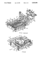
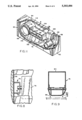
- FIG. 2 is a perspective view, again with portions broken away, of a convective dryer in accordance with the present invention
- FIG. 3 is a top plan view on an enlarged scale of the dryer shown in FIG. 2, with portions of the top wall and other internal components partially broken away for illustrative purposes;
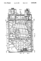
- FIGS. 4, 5, 6 and 7 are sectional views on a further enlarged scale taken respectively along lines 4--4, 5--5, 6--6 and 7--7 of FIG. 3;
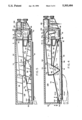
- FIG. 8 is a sectional view on an enlarged scale taken along line 8--8 of FIG. 4;
- FIG. 9 is a sectional view on an enlarged scale taken along line 9--9 of FIG. 4;
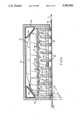
- FIG. 10 is a perspective view of a return duct and an adjacent nozzle assembly.
- FIG. 11 is a perspective view of components contained in the second chamber of a dryer module.
- the dryer includes at least one equipment module 54a arranged on one side of the path "P" of a moving Web "W".
- the dryer includes an additional mating equipment module 54b on the opposite side of the path P.
- each of the modules 54a, 54b are essentially identical, and thus the remaining description will focus primarily on the upper module 54a, with the understanding that the same description would be applicable to lower module 54b.
- Module 54a includes an insulated housing having front and back walls 56, 58 interconnected by side walls 60, 62 and closed by a top wall 64. The bottom of the housing opens towards the web path P.
- Cross-machine stiffeners 66 are located at the junctions of the top wall 64 with the side walls 60, 62. The stiffeners impart flexural and torsional rigidity to the open-bottomed housing structure.
- An inner housing partition 68 extends in parallel relationship to the back wall 58 and serves to interiorly subdivide the housing into first and second chambers A, B.
- the first chamber A faces and opens towards the web path P.
- the second chamber B extends laterally beyond path P, with its bottom being closed by a bottom wall 70.
- a supply duct 72 extends from the second chamber B into the first chamber A.
- Duct 72 has a relatively narrow entry section defining a burner chamber 72a extending through the partition 68, a diverging intermediate section 72b, and a relatively wide delivery end 72c located approximately at the center of both the first chamber A and the path P of web travel.
- Nozzle assemblies 74 extend laterally across the path P within the first housing chamber A.
- the nozzle assemblies are typically mounted to the housing front wall 56 and to the inner partition 68 by means of pin and bracket assemblies 76 which allow for differential thermal expansion.
- One such assembly 76 is depicted in FIG. 8 as including a pin 78 protruding from an end of a respective nozzle assembly 74.
- the pin 78 is slidable received in a hole in a U-shaped support bracket 80 secured to the adjacent housing wall 56. This arrangement accommodates thermal expansion and contraction of the nozzle assemblies in relation to the overall housing structure.
- Each nozzle assembly 74 consists of a lower air bar portion 82 located directly adjacent to the web path P, and an upper manifold section 84. As shown in FIG. 9, the air bar portion 82 defines a pair of slot-like orifices 86 communicating with the interior of the manifold section 84.
- Each manifold 84 section tapers in cross-sectional area in opposite directions from a maximum at its center to a minimum at its ends. The center of each manifold section is attached to the delivery end 72c of the supply duct 72 and is in communication with the interior of the supply duct via an inlet port 88.
- the supply duct 72 is provided internally with first diffusing means comprising a plurality of angularly arranged mutually spaced baffles 90 defining divergent flow paths leading to the inlet ports 88 of the manifold sections 84.
- the baffles 90 serve to enhance the uniformity of air distribution flowing through the supply duct 72 to the orifices 86 via the inlet ports 88.
- the baffles 90 also serve to maintain the structural integrity of the supply duct 72.
- the manifold sections 84 further include internal second diffusing means in the form of perforated V-shaped baffles 92 centrally located adjacent to the entry ports 88.
- the perforated baffles 92 act as turning vanes to further enhance uniformity of air flow to the orifices 86.
- each return duct 94 includes doubly tapered insulated side walls 96 matching the double taper of the nozzle assemblies.
- the ducts 94 have perforated bottom walls 98, and insulated top walls 100, the central portions of which are connected to and extending beneath the delivery end 72c of supply duct 72.
- Outlet ports 102 are arranged in the top wall 100 of each duct 94 on opposite sides of the delivery end 72c of the supply duct.
- Sealing plates 104, 106 extend respectively from the housing front wall 56 and the inner partition 68 to overlap the sloping top surfaces of the nozzle assemblies 74 and return ducts 94 interposed therebetween.
- the sealing plates 104, 106 cooperate with the nozzle assemblies 74 and return ducts 94 to form a return plenum 108 in the upper portion of housing chamber A.
- Drying air flows through the supply duct 72 in the direction schematically depicted in FIG. 4 where it is distributed by the baffles 92 to the inlet ports 88 of the nozzle assemblies 74.
- the drying air enters each nozzle assembly via its inlet port, and is then diffused by the perforated baffles 92 for even distribution to the orifices 86.
- the drying air flows adjacent to the web W, and then leaves the vicinity of the web to enter the return ducts 94 via their perforated bottom walls 88.
- the drying air then flows through the return ducts 94 to exit via their outlet ports 102 into the return plenum 108.
- a supply fan inlet port 110 and an exhaust port 112 are provided in the partition 68.
- Inlet port 110 is connected to a centrifugal fan 114 by a short perforated duct 116. Both the perforated duct 116 and the fan 114 are located in the second chamber B.
- An internal exhaust duct 118 extends from the vicinity of the inlet port 110 to the housing side wall 62 and leads to the exhaust port 112.
- the exhaust port is connected to centrifugal exhaust fan 122 which in turn is connected to an exhaust duct 124.
- Variable speed drive motors 126, 128 for the supply fan 114 and exhaust fan 122 are cantilevered off of the back housing wall 58.
- the rotational axis of fan 114 is parallel to the length of supply duct 72. Air is drawn by the fan along its axis and is delivered circumferentially to a discharge scroll 130 leading to a diffusing elbow 132. Elbow 132 is designed to efficiently collect and direct the air discharge from fan 114 through a 90° turn before delivering it to a second elbow 134 which effects another 90° turn into the burner chamber 72a of supply duct 72. Turning vanes 136 in the diffusing elbow 132 are configured and arranged to equally subdivide the fan discharge, thereby correcting what would otherwise be a non-uniform delivery characteristic of centrifugal fans.
- a gas-fed line burner 138 is located in the burner chamber 72a of the supply duct 72.
- the burner 13 8 may be supported by an additional baffle 140 which subdivides the elbow 134 into two flow paths insuring equal amounts of air flow past either side of the burner.
- Burner 138 provides the energy source required to reheat drying air being recirculated through the system.
- Pipe stiffeners 141 reinforce the free ends of the baffles 92 and protect them against distortion due to radiant heat from the flame of burner 138.
- Make-up air is admitted to the second chamber B via a damper controlled inlet 142. From here, the make-up air is entrained into the system via the perforated duct 116 on the intake side of supply fan 114. Discharge air is removed from the system at a location adjacent to the supply fan inlet port 110 by being drawn into the internal exhaust duct 118 leading to exhaust port 122.
- piston-cylinder units 144 may be employed to lift the upper dryer module 54a when there is a need to gain access to the dryer interior.
- the line-type burner 138 provides good mixing in an extremely compact space with a very short flame, thereby allowing the burner to be placed in a burner chamber 72a forming part of the supply duct 72. Heated air is efficiently distributed to the cross-machine center of chamber A at the center of the path P traveled by the web W.
- the doubly tapered nozzle assemblies 70 further enhance uniform distribution of air to the web while at the same time eliminating the need for intermediate headers of the type shown at 14 in the prior art arrangement of FIG. 1.
- External flexible connections are also eliminated, except perhaps where required in the exhaust ducting, gas and electrical service leading from the shiftable dryer module 54 a. Here, however, any degradation of the flexible connection will not be troublesome because resulting debris will simply be exhausted rather than being recirculated through the system.
- the insulated return ducts 94 prevent shunt losses between the incoming and outgoing air streams, thereby promoting cross-machine uniformity of supply air temperature and web drying rate while also promoting efficiency.
- the internal exhaust duct 118 ensures that exhaust flow is collected near the inlet port 110 to the supply fan 114, thereby preventing changes in the rate of exhaust flow from altering the return flow distribution to the nozzle assemblies. Make-up air is uniformly introduced into the system via the perforated duct 116 on the intake side of the supply fan 114.
- the downstream location of the burner 138 in relation to the supply fan 114 ensures that the fan is protected from the hazard of receiving poorly mixed flow from the burner with the possibility of overheating the fan.
- two independently operable modules 54a, 54b are employed on opposite sides of the web. This arrangement makes it possible to easily vary and control air velocity, temperature and humidity independently on each web side, thereby greatly expanding the controllability of the drying process.
- alternative heating means other than the disclosed line-type burner 138 may be employed.
- Such alternative heating means might include steam coils arranged at the same or other locations in the recirculating air flow.
- the heat source should be located sufficiently in advance of the delivery end of the supply duct so as to insure adequate mixing and a substantially uniform elevated temperature before the heated air enters the individual nozzle assemblies.
Abstract
Description
Claims (24)
Priority Applications (4)
| Application Number | Priority Date | Filing Date | Title |
|---|---|---|---|
| US07/866,150 US5303484A (en) | 1992-04-09 | 1992-04-09 | Compact convective web dryer |
| CA002093066A CA2093066C (en) | 1992-04-09 | 1993-03-31 | Compact convective web dryer |
| EP93302636A EP0565321A1 (en) | 1992-04-09 | 1993-04-02 | A compact convective web dryer |
| JP5105955A JPH06184978A (en) | 1992-04-09 | 1993-04-09 | Convection-type drying system for web material |
Applications Claiming Priority (1)
| Application Number | Priority Date | Filing Date | Title |
|---|---|---|---|
| US07/866,150 US5303484A (en) | 1992-04-09 | 1992-04-09 | Compact convective web dryer |
Publications (1)
| Publication Number | Publication Date |
|---|---|
| US5303484A true US5303484A (en) | 1994-04-19 |
Family
ID=25347027
Family Applications (1)
| Application Number | Title | Priority Date | Filing Date |
|---|---|---|---|
| US07/866,150 Expired - Lifetime US5303484A (en) | 1992-04-09 | 1992-04-09 | Compact convective web dryer |
Country Status (4)
| Country | Link |
|---|---|
| US (1) | US5303484A (en) |
| EP (1) | EP0565321A1 (en) |
| JP (1) | JPH06184978A (en) |
| CA (1) | CA2093066C (en) |
Cited By (30)
| Publication number | Priority date | Publication date | Assignee | Title |
|---|---|---|---|---|
| US5555644A (en) * | 1994-10-17 | 1996-09-17 | W.R. Grace & Co.-Conn. | Fluid cylinder retraction locking device |
| US5564200A (en) * | 1993-10-15 | 1996-10-15 | Solipat Ag | Device for heat treatment of a continuously guided material web, in particular a textile web |
| US5771602A (en) * | 1995-10-25 | 1998-06-30 | Valmet Corporation | Method and device for drying a coating on a paper web or equivalent |
| US6018842A (en) * | 1997-08-13 | 2000-02-01 | Billco Manufacturing, Inc. | Glass washing machine |
| US6237248B1 (en) | 1998-09-11 | 2001-05-29 | Voith Sulzer Papiertechnik Patent Gmbh | Convection drier and method of use for manufacturing a material web |
| US6256903B1 (en) * | 1996-08-23 | 2001-07-10 | Research, Incorporated | Coating dryer system |
| US6289607B1 (en) | 1997-05-30 | 2001-09-18 | Metso Paper, Inc. | Flotation dryer unit and method of use |
| US6393729B1 (en) * | 1997-10-03 | 2002-05-28 | Abb Ab | Method, control paradigm and means for monitoring and controlling the process variables of a process gas flowing through a dryer hood used in a drying process |
| US6651357B2 (en) * | 2001-01-12 | 2003-11-25 | Megtec Systems, Inc. | Web dryer with fully integrated regenerative heat source and control thereof |
| US20080276488A1 (en) * | 2007-05-07 | 2008-11-13 | Paul Seidl | Step air foil web stabilizer |
| US20090321974A1 (en) * | 2008-04-14 | 2009-12-31 | Gregory Branch | Roll fed flotation/impingement air ovens and related thermoforming systems for corrugation-free heating and expanding of gas impregnated thermoplastic webs |
| US20100052201A1 (en) * | 2008-03-03 | 2010-03-04 | Microgreen Polymers, Inc. | Foamed cellular panels and related methods |
| US20100062235A1 (en) * | 2007-01-17 | 2010-03-11 | Krishna Nadella | Multi-layered foamed polymeric objects having segmented and varying physical properties and related methods |
| US20100112301A1 (en) * | 2008-11-04 | 2010-05-06 | Microgreen Polymers, Inc. | Apparatus and method for interleaving polymeric roll for gas impregnation and solid-state foam processing |
| US20100163450A1 (en) * | 2003-05-17 | 2010-07-01 | Microgreen Polymers, Inc. | Deep drawn microcellularly foamed polymeric containers made via solid-state gas impregnation thermoforming |
| US20110081524A1 (en) * | 2007-01-17 | 2011-04-07 | Microgreen Polymers, Inc. | Multi-layered foamed polymeric objects and related methods |
| US7941937B2 (en) * | 2002-11-26 | 2011-05-17 | Lg Electronics Inc. | Laundry dryer control method |
| US20110195165A1 (en) * | 2010-02-08 | 2011-08-11 | Cahill John E | Material and sheet for packaging bacon and/or other meats, and methods for making and using the same |
| US20130074361A1 (en) * | 2011-09-22 | 2013-03-28 | Metso Paper, Inc. | Drying Arrangement and Method for Drying a Moving Web |
| US8517709B2 (en) | 2008-06-13 | 2013-08-27 | Microgreen Polymers, Inc. | Methods and pressure vessels for solid-state microcellular processing of thermoplastic rolls or sheets |
| US9296185B2 (en) | 2010-04-19 | 2016-03-29 | Dart Container Corporation | Method for joining thermoplastic polymer material |
| US20160251779A1 (en) * | 2013-10-18 | 2016-09-01 | Unicharm Ccorporation | Bulk recovery apparatus for nonwoven fabric and bulk recovery method for the same |
| US9914247B2 (en) | 2012-02-29 | 2018-03-13 | Dart Container Corporation | Method for infusing a gas into a thermoplastic material, and related systems |
| US10544001B2 (en) | 2013-01-14 | 2020-01-28 | Dart Container Corporation | Systems for unwinding a roll of thermoplastic material interleaved with a porous material, and related methods |
| US10823502B2 (en) * | 2013-08-14 | 2020-11-03 | Whirlpool Corporation | Appliance for drying articles |
| US11029088B2 (en) | 2013-10-02 | 2021-06-08 | Whirlpool Corporation | Method and apparatus for drying articles |
| US11078619B2 (en) | 2015-03-23 | 2021-08-03 | Whirlpool Corporation | Apparatus for drying articles |
| US11459696B2 (en) | 2013-08-23 | 2022-10-04 | Whirlpool Corporation | Appliance for drying articles |
| US11519130B2 (en) | 2013-10-16 | 2022-12-06 | Whirlpool Corporation | Method and apparatus for detecting an energized e-field |
| US11655583B2 (en) | 2013-07-17 | 2023-05-23 | Whirlpool Corporation | Method for drying articles |
Families Citing this family (5)
| Publication number | Priority date | Publication date | Assignee | Title |
|---|---|---|---|---|
| US5784804A (en) * | 1996-03-25 | 1998-07-28 | Asea Brown Boveri, Inc. | Yankee hood with integral air heating system |
| CA2216591C (en) * | 1997-09-24 | 2004-05-11 | Asea Brown Boveri Inc. | High temperature yankee hood |
| CN102782431B (en) * | 2009-12-30 | 2015-08-19 | 贝宁格泽尔有限公司 | For the apparatus and method of the sheet material of heat treatment continus convergence |
| CN110595196B (en) * | 2019-08-22 | 2024-03-26 | 广东工业大学 | Small-size high-efficient dehumidification heat pump drying device |
| SE2250852A1 (en) * | 2022-07-06 | 2024-01-07 | Northvolt Ab | A drying chamber assembly for drying battery electrodes |
Citations (11)
| Publication number | Priority date | Publication date | Assignee | Title |
|---|---|---|---|---|
| US2772486A (en) * | 1952-05-29 | 1956-12-04 | Svenska Flaektfabriken Ab | Apparatus for conditioning, preferably drying, of a web-like material |
| US3308556A (en) * | 1964-10-19 | 1967-03-14 | Proctor & Schwartz Inc | Material treating apparatus |
| US3319353A (en) * | 1964-03-30 | 1967-05-16 | Niwa Machinery Company Ltd | Pressing and drying devices for corrugated board manufacturing equipment |
| US4085522A (en) * | 1972-10-30 | 1978-04-25 | Hoechst Aktiengesellschaft | Method and apparatus for freely suspending moving webs of material |
| FR2391437A1 (en) * | 1977-05-18 | 1978-12-15 | Air Ind | IMPROVEMENTS TO TREATMENT FACILITIES FOR A PRODUCT IN A GASEOUS MEDIUM |
| US4227317A (en) * | 1973-04-21 | 1980-10-14 | Vepa Aktiengesellschaft | Apparatus for the heat treatment of textiles |
| US4295284A (en) * | 1979-07-05 | 1981-10-20 | Marshall And Williams Company | Dryer range |
| US4425719A (en) * | 1982-03-15 | 1984-01-17 | W. R. Grace & Co. | Compact air bar assembly for contactless web support |
| US4435909A (en) * | 1981-11-30 | 1984-03-13 | Marshall And Williams Company | Automatic lint screen |
| EP0346042A2 (en) * | 1988-06-07 | 1989-12-13 | W.R. Grace & Co.-Conn. | Air flotation dryer with built-in afterburner |
| US4989348A (en) * | 1986-10-22 | 1991-02-05 | Hilmar Vits | Continuous-flow dryer for material webs, in particular offset dryer process for the thermal operation of a continuous-flow dryer |
Family Cites Families (1)
| Publication number | Priority date | Publication date | Assignee | Title |
|---|---|---|---|---|
| JPS538832A (en) * | 1976-07-13 | 1978-01-26 | Matsushita Electric Ind Co Ltd | Cease heater |
-
1992
- 1992-04-09 US US07/866,150 patent/US5303484A/en not_active Expired - Lifetime
-
1993
- 1993-03-31 CA CA002093066A patent/CA2093066C/en not_active Expired - Fee Related
- 1993-04-02 EP EP93302636A patent/EP0565321A1/en not_active Withdrawn
- 1993-04-09 JP JP5105955A patent/JPH06184978A/en active Pending
Patent Citations (12)
| Publication number | Priority date | Publication date | Assignee | Title |
|---|---|---|---|---|
| US2772486A (en) * | 1952-05-29 | 1956-12-04 | Svenska Flaektfabriken Ab | Apparatus for conditioning, preferably drying, of a web-like material |
| US3319353A (en) * | 1964-03-30 | 1967-05-16 | Niwa Machinery Company Ltd | Pressing and drying devices for corrugated board manufacturing equipment |
| US3308556A (en) * | 1964-10-19 | 1967-03-14 | Proctor & Schwartz Inc | Material treating apparatus |
| US4085522A (en) * | 1972-10-30 | 1978-04-25 | Hoechst Aktiengesellschaft | Method and apparatus for freely suspending moving webs of material |
| US4227317A (en) * | 1973-04-21 | 1980-10-14 | Vepa Aktiengesellschaft | Apparatus for the heat treatment of textiles |
| FR2391437A1 (en) * | 1977-05-18 | 1978-12-15 | Air Ind | IMPROVEMENTS TO TREATMENT FACILITIES FOR A PRODUCT IN A GASEOUS MEDIUM |
| US4295284A (en) * | 1979-07-05 | 1981-10-20 | Marshall And Williams Company | Dryer range |
| US4435909A (en) * | 1981-11-30 | 1984-03-13 | Marshall And Williams Company | Automatic lint screen |
| US4425719A (en) * | 1982-03-15 | 1984-01-17 | W. R. Grace & Co. | Compact air bar assembly for contactless web support |
| US4989348A (en) * | 1986-10-22 | 1991-02-05 | Hilmar Vits | Continuous-flow dryer for material webs, in particular offset dryer process for the thermal operation of a continuous-flow dryer |
| EP0346042A2 (en) * | 1988-06-07 | 1989-12-13 | W.R. Grace & Co.-Conn. | Air flotation dryer with built-in afterburner |
| US5112220A (en) * | 1988-06-07 | 1992-05-12 | W. R. Grace & Co.-Conn. | Air flotation dryer with built-in afterburner |
Cited By (46)
| Publication number | Priority date | Publication date | Assignee | Title |
|---|---|---|---|---|
| US5564200A (en) * | 1993-10-15 | 1996-10-15 | Solipat Ag | Device for heat treatment of a continuously guided material web, in particular a textile web |
| EP0734507B1 (en) * | 1994-10-17 | 1999-03-31 | Megtec Systems, Inc. | Fluid cylinder retraction locking device |
| US5555644A (en) * | 1994-10-17 | 1996-09-17 | W.R. Grace & Co.-Conn. | Fluid cylinder retraction locking device |
| US5771602A (en) * | 1995-10-25 | 1998-06-30 | Valmet Corporation | Method and device for drying a coating on a paper web or equivalent |
| US6256903B1 (en) * | 1996-08-23 | 2001-07-10 | Research, Incorporated | Coating dryer system |
| US6289607B1 (en) | 1997-05-30 | 2001-09-18 | Metso Paper, Inc. | Flotation dryer unit and method of use |
| US6018842A (en) * | 1997-08-13 | 2000-02-01 | Billco Manufacturing, Inc. | Glass washing machine |
| US6393729B1 (en) * | 1997-10-03 | 2002-05-28 | Abb Ab | Method, control paradigm and means for monitoring and controlling the process variables of a process gas flowing through a dryer hood used in a drying process |
| US6237248B1 (en) | 1998-09-11 | 2001-05-29 | Voith Sulzer Papiertechnik Patent Gmbh | Convection drier and method of use for manufacturing a material web |
| US6651357B2 (en) * | 2001-01-12 | 2003-11-25 | Megtec Systems, Inc. | Web dryer with fully integrated regenerative heat source and control thereof |
| US7941937B2 (en) * | 2002-11-26 | 2011-05-17 | Lg Electronics Inc. | Laundry dryer control method |
| US20100163450A1 (en) * | 2003-05-17 | 2010-07-01 | Microgreen Polymers, Inc. | Deep drawn microcellularly foamed polymeric containers made via solid-state gas impregnation thermoforming |
| US10391687B2 (en) | 2003-05-17 | 2019-08-27 | Dart Container Corporation | Deep drawn microcellularly foamed polymeric containers made via solid-state gas impregnation thermoforming |
| US9770854B2 (en) | 2003-05-17 | 2017-09-26 | Dart Container Corporation | Deep drawn microcellularly foamed polymeric containers made via solid-state gas impregnation thermoforming |
| US9296126B2 (en) | 2003-05-17 | 2016-03-29 | Microgreen Polymers, Inc. | Deep drawn microcellularly foamed polymeric containers made via solid-state gas impregnation thermoforming |
| US20100062235A1 (en) * | 2007-01-17 | 2010-03-11 | Krishna Nadella | Multi-layered foamed polymeric objects having segmented and varying physical properties and related methods |
| US10029401B2 (en) | 2007-01-17 | 2018-07-24 | Dart Container Corporation | Multi-layered foamed polymeric objects and related methods |
| US8877331B2 (en) | 2007-01-17 | 2014-11-04 | MicroGREEN Polymers | Multi-layered foamed polymeric objects having segmented and varying physical properties and related methods |
| US20110081524A1 (en) * | 2007-01-17 | 2011-04-07 | Microgreen Polymers, Inc. | Multi-layered foamed polymeric objects and related methods |
| US8377548B2 (en) | 2007-01-17 | 2013-02-19 | Microgreen Polymers Inc. | Multi-layered foamed polymeric objects and related methods |
| US20080276488A1 (en) * | 2007-05-07 | 2008-11-13 | Paul Seidl | Step air foil web stabilizer |
| US8061055B2 (en) * | 2007-05-07 | 2011-11-22 | Megtec Systems, Inc. | Step air foil web stabilizer |
| US20100052201A1 (en) * | 2008-03-03 | 2010-03-04 | Microgreen Polymers, Inc. | Foamed cellular panels and related methods |
| US9884440B2 (en) | 2008-04-14 | 2018-02-06 | Dart Container Corporation | Roll fed flotation/impingement air ovens and related thermoforming systems for corrugation-free heating and expanding of gas impregnated thermoplastic webs |
| US8568125B2 (en) | 2008-04-14 | 2013-10-29 | Microgreen Polymers Inc. | Roll fed flotation/impingement air ovens and related thermoforming systems for corrugation-free heating and expanding of gas impregnated thermoplastic webs |
| US9427903B2 (en) | 2008-04-14 | 2016-08-30 | Dart Container Corporation | Roll fed flotation/impingement air ovens and related thermoforming systems for corrugation-free heating and expanding of gas impregnated thermoplastic webs |
| US20090321974A1 (en) * | 2008-04-14 | 2009-12-31 | Gregory Branch | Roll fed flotation/impingement air ovens and related thermoforming systems for corrugation-free heating and expanding of gas impregnated thermoplastic webs |
| US8858849B2 (en) | 2008-06-13 | 2014-10-14 | Microgreen Polymers Inc. | Methods and pressure vessels for solid-state microcellular processing of thermoplastic rolls or sheets |
| US8517709B2 (en) | 2008-06-13 | 2013-08-27 | Microgreen Polymers, Inc. | Methods and pressure vessels for solid-state microcellular processing of thermoplastic rolls or sheets |
| US8827197B2 (en) | 2008-11-04 | 2014-09-09 | Microgreen Polymers Inc | Apparatus and method for interleaving polymeric roll for gas impregnation and solid-state foam processing |
| US20100112301A1 (en) * | 2008-11-04 | 2010-05-06 | Microgreen Polymers, Inc. | Apparatus and method for interleaving polymeric roll for gas impregnation and solid-state foam processing |
| US20110195165A1 (en) * | 2010-02-08 | 2011-08-11 | Cahill John E | Material and sheet for packaging bacon and/or other meats, and methods for making and using the same |
| US9296185B2 (en) | 2010-04-19 | 2016-03-29 | Dart Container Corporation | Method for joining thermoplastic polymer material |
| US20130074361A1 (en) * | 2011-09-22 | 2013-03-28 | Metso Paper, Inc. | Drying Arrangement and Method for Drying a Moving Web |
| US9914247B2 (en) | 2012-02-29 | 2018-03-13 | Dart Container Corporation | Method for infusing a gas into a thermoplastic material, and related systems |
| US10544001B2 (en) | 2013-01-14 | 2020-01-28 | Dart Container Corporation | Systems for unwinding a roll of thermoplastic material interleaved with a porous material, and related methods |
| US11655583B2 (en) | 2013-07-17 | 2023-05-23 | Whirlpool Corporation | Method for drying articles |
| US10823502B2 (en) * | 2013-08-14 | 2020-11-03 | Whirlpool Corporation | Appliance for drying articles |
| US11459696B2 (en) | 2013-08-23 | 2022-10-04 | Whirlpool Corporation | Appliance for drying articles |
| US11029088B2 (en) | 2013-10-02 | 2021-06-08 | Whirlpool Corporation | Method and apparatus for drying articles |
| US11686037B2 (en) | 2013-10-02 | 2023-06-27 | Whirlpool Corporation | Method and apparatus for drying articles |
| US11519130B2 (en) | 2013-10-16 | 2022-12-06 | Whirlpool Corporation | Method and apparatus for detecting an energized e-field |
| US9809913B2 (en) * | 2013-10-18 | 2017-11-07 | Unicharm Corporation | Bulk recovery apparatus for nonwoven fabric and bulk recovery method for the same |
| US20160251779A1 (en) * | 2013-10-18 | 2016-09-01 | Unicharm Ccorporation | Bulk recovery apparatus for nonwoven fabric and bulk recovery method for the same |
| US11078619B2 (en) | 2015-03-23 | 2021-08-03 | Whirlpool Corporation | Apparatus for drying articles |
| US11692298B2 (en) | 2015-03-23 | 2023-07-04 | Whirlpool Corporation | Method of drying articles |
Also Published As
| Publication number | Publication date |
|---|---|
| EP0565321A1 (en) | 1993-10-13 |
| JPH06184978A (en) | 1994-07-05 |
| CA2093066A1 (en) | 1993-10-10 |
| CA2093066C (en) | 1997-01-21 |
Similar Documents
| Publication | Publication Date | Title |
|---|---|---|
| US5303484A (en) | Compact convective web dryer | |
| FI78756C (en) | Method and apparatus for drying a moving web | |
| US3012335A (en) | Treating web-like material by a gaseous medium | |
| JPS5832150B2 (en) | Method and apparatus for guiding and processing strip material in suspension | |
| EP1105566B1 (en) | Method and apparatus for improving the drying capacity of a hood covering a yankee cylinder | |
| CA2242044A1 (en) | Plenum damper and baffle plate arrangement for pneumatic distribution system | |
| JPH09505387A (en) | Improved equipment related to web drying | |
| US6837706B2 (en) | Unit for drying gypsum plaster board | |
| US5784804A (en) | Yankee hood with integral air heating system | |
| US4905381A (en) | Open top compact dryer oven for a web | |
| US4320587A (en) | Dryer for a continuously traveling web | |
| US5619808A (en) | Apparatus for blowing air at a length of textile fabric | |
| US5915813A (en) | Apparatus and method for drying a wet web and modifying the moisture profile thereof | |
| CA2668451C (en) | Apparatus and method for the uniform drying of board materials | |
| JPH0310870B2 (en) | ||
| US6413470B1 (en) | Device for guiding bands in a suspended manner | |
| US5564200A (en) | Device for heat treatment of a continuously guided material web, in particular a textile web | |
| US4295284A (en) | Dryer range | |
| JP7310054B2 (en) | Method and apparatus for drying boards | |
| US4170075A (en) | Nozzle for web processing apparatus | |
| CZ302322B6 (en) | Device for blowing a fluid on at least a surface of a thin element and associated blowing unit | |
| US5233764A (en) | Turbulent airflow hot shelf tower dryer | |
| US6210268B1 (en) | Air mixer for static mixing of two air streams | |
| JP3602921B2 (en) | Hollow wood drying equipment | |
| EP1079011B1 (en) | Hot air drier for warp sizer |
Legal Events
| Date | Code | Title | Description |
|---|---|---|---|
| AS | Assignment |
Owner name: THERMO ELECTRON WEB SYSTEMS, INC., A MA CORP., MAS Free format text: ASSIGNMENT OF ASSIGNORS INTEREST.;ASSIGNORS:HAGEN, KENNETH G.;LEEMAN, DAVID A.;REEL/FRAME:006099/0644 Effective date: 19920408 |
|
| FEPP | Fee payment procedure |
Free format text: PETITION RELATED TO MAINTENANCE FEES FILED (ORIGINAL EVENT CODE: PMFP); ENTITY STATUS OF PATENT OWNER: LARGE ENTITY |
|
| FP | Lapsed due to failure to pay maintenance fee |
Effective date: 19980419 |
|
| FPAY | Fee payment |
Year of fee payment: 4 |
|
| SULP | Surcharge for late payment | ||
| FEPP | Fee payment procedure |
Free format text: PETITION RELATED TO MAINTENANCE FEES GRANTED (ORIGINAL EVENT CODE: PMFG); ENTITY STATUS OF PATENT OWNER: LARGE ENTITY |
|
| AS | Assignment |
Owner name: THERMO WISCONSIN, INC., WISCONSIN Free format text: MERGER;ASSIGNOR:THERMO WEB SYSTEMS, INC.;REEL/FRAME:009678/0294 Effective date: 19990106 |
|
| STCF | Information on status: patent grant |
Free format text: PATENTED CASE |
|
| PRDP | Patent reinstated due to the acceptance of a late maintenance fee |
Effective date: 19990226 |
|
| FPAY | Fee payment |
Year of fee payment: 8 |
|
| FPAY | Fee payment |
Year of fee payment: 12 |
|
| AS | Assignment |
Owner name: LEHMAN COMMERCIAL PAPER, INC., NEW YORK Free format text: GUARANTEE AND COLLATERAL AGREEMENT;ASSIGNOR:MEGTEC SYSTEMS, INC.;REEL/FRAME:020525/0827 Effective date: 20071203 |
|
| AS | Assignment |
Owner name: MEGTEC SYSTEMS, INC., WISCONSIN Free format text: NUNC PRO TUNC ASSIGNMENT;ASSIGNOR:THERMO WISCONSIN, INC.;REEL/FRAME:021561/0918 Effective date: 20080923 |
|
| AS | Assignment |
Owner name: MEGTEC SYSTEMS KG, WISCONSIN Free format text: RELEASED BY SECURED PARTY;ASSIGNOR:LEHMAN COMMERCIAL PAPER, INC.;REEL/FRAME:021630/0602 Effective date: 20080924 Owner name: MEGTEC SYSTEMS AB, WISCONSIN Free format text: RELEASED BY SECURED PARTY;ASSIGNOR:LEHMAN COMMERCIAL PAPER, INC.;REEL/FRAME:021630/0602 Effective date: 20080924 Owner name: MEGTEC SYSTEMS, INC., WISCONSIN Free format text: RELEASED BY SECURED PARTY;ASSIGNOR:LEHMAN COMMERCIAL PAPER, INC.;REEL/FRAME:021630/0602 Effective date: 20080924 Owner name: MEGTEC SYSTEMS AUSTRALIA, INC., WISCONSIN Free format text: RELEASED BY SECURED PARTY;ASSIGNOR:LEHMAN COMMERCIAL PAPER, INC.;REEL/FRAME:021630/0602 Effective date: 20080924 Owner name: MTS ASIA, INC., WISCONSIN Free format text: RELEASED BY SECURED PARTY;ASSIGNOR:LEHMAN COMMERCIAL PAPER, INC.;REEL/FRAME:021630/0602 Effective date: 20080924 Owner name: MEGTEC SYSTEMS, S.A.S., WISCONSIN Free format text: RELEASED BY SECURED PARTY;ASSIGNOR:LEHMAN COMMERCIAL PAPER, INC.;REEL/FRAME:021630/0602 Effective date: 20080924 Owner name: MEGTEC SYSTEMS AMAL AB, WISCONSIN Free format text: RELEASED BY SECURED PARTY;ASSIGNOR:LEHMAN COMMERCIAL PAPER, INC.;REEL/FRAME:021630/0602 Effective date: 20080924 Owner name: SEQUA GMBH & CO., WISCONSIN Free format text: RELEASED BY SECURED PARTY;ASSIGNOR:LEHMAN COMMERCIAL PAPER, INC.;REEL/FRAME:021630/0602 Effective date: 20080924 |
|
| AS | Assignment |
Owner name: MEGTEC SYSTEMS, INC., WISCONSIN Free format text: TERMINATION OF SECURITY INTEREST IN PATENTS AT REEL/FRAME NOS. 20525/0827 AND 20571/0001;ASSIGNOR:LEHMAN COMMERCIAL PAPER, INC.;REEL/FRAME:021617/0548 Effective date: 20080924 |
|
| AS | Assignment |
Owner name: BANK OF AMERICA, N.A., AS ADMINISTRATIVE AGENT, NO Free format text: SECURITY AGREEMENT;ASSIGNOR:MEGTEC SYSTEMS, INC.;REEL/FRAME:021719/0141 Effective date: 20080924 |
|
| AS | Assignment |
Owner name: TD BANK, N.A., AS ADMINISTRATIVE AGENT, CONNECTICU Free format text: PATENT COLLATERAL ASSIGNMENT AND SECURITY AGREEMENT;ASSIGNOR:MEGTEC SYSTEMS, INC.;REEL/FRAME:027396/0140 Effective date: 20111216 |
|
| AS | Assignment |
Owner name: MEGTEC SYSTEMS, INC., WISCONSIN Free format text: TERMINATION AND RELEASE OF SECURITY INTEREST IN PATENT AND TRADEMARK RIGHTS;ASSIGNOR:BANK OF AMERICA, N.A., AS ADMINISTRATIVE AGENT;REEL/FRAME:027430/0112 Effective date: 20111216 |