US5301056A - Optical distribution system - Google Patents
Optical distribution system Download PDFInfo
- Publication number
- US5301056A US5301056A US08/107,046 US10704693A US5301056A US 5301056 A US5301056 A US 5301056A US 10704693 A US10704693 A US 10704693A US 5301056 A US5301056 A US 5301056A
- Authority
- US
- United States
- Prior art keywords
- output
- signal
- optical
- coupled
- input coupled
- Prior art date
- Legal status (The legal status is an assumption and is not a legal conclusion. Google has not performed a legal analysis and makes no representation as to the accuracy of the status listed.)
- Expired - Lifetime
Links
- 230000003287 optical effect Effects 0.000 title claims abstract description 117
- 238000001914 filtration Methods 0.000 claims 4
- 230000008878 coupling Effects 0.000 claims 2
- 238000010168 coupling process Methods 0.000 claims 2
- 238000005859 coupling reaction Methods 0.000 claims 2
- 239000000835 fiber Substances 0.000 claims 2
- 230000002194 synthesizing effect Effects 0.000 claims 2
- 239000000470 constituent Substances 0.000 abstract description 3
- 238000010586 diagram Methods 0.000 description 13
- 238000004891 communication Methods 0.000 description 12
- 230000005540 biological transmission Effects 0.000 description 4
- 238000000034 method Methods 0.000 description 3
- 230000004075 alteration Effects 0.000 description 2
- 238000012986 modification Methods 0.000 description 2
- 230000004048 modification Effects 0.000 description 2
- 230000010267 cellular communication Effects 0.000 description 1
- 230000001413 cellular effect Effects 0.000 description 1
- 239000004020 conductor Substances 0.000 description 1
- 230000009977 dual effect Effects 0.000 description 1
Images


Classifications
-
- H—ELECTRICITY
- H04—ELECTRIC COMMUNICATION TECHNIQUE
- H04B—TRANSMISSION
- H04B10/00—Transmission systems employing electromagnetic waves other than radio-waves, e.g. infrared, visible or ultraviolet light, or employing corpuscular radiation, e.g. quantum communication
- H04B10/25—Arrangements specific to fibre transmission
- H04B10/2575—Radio-over-fibre, e.g. radio frequency signal modulated onto an optical carrier
- H04B10/25752—Optical arrangements for wireless networks
- H04B10/25753—Distribution optical network, e.g. between a base station and a plurality of remote units
- H04B10/25754—Star network topology
-
- H—ELECTRICITY
- H04—ELECTRIC COMMUNICATION TECHNIQUE
- H04J—MULTIPLEX COMMUNICATION
- H04J14/00—Optical multiplex systems
- H04J14/02—Wavelength-division multiplex systems
- H04J14/0298—Wavelength-division multiplex systems with sub-carrier multiplexing [SCM]
Definitions
- the present invention relates, in general, to communication systems and, more particularly, to optical distribution systems.
- Site acquisition for the transmission and switching hardware can account for half or more of the total cost of establishing a new cell site in a metropolitan area.
- the present invention provides an optical distribution system which permits multiple cells of a communication network to be covered by one centralized base station.
- the downlink portion of the optical distribution system consists of a multiplexing means for combining a plurality of signals into a combined output signal.
- the combined output signal is forwarded to a first transducer means for converting the combined output signal to an optical signal.
- the optical signal from the first transducer means is then transmitted over a first optical line to a first splitting means for splitting the optical signal into a plurality of optical signals.
- Each of the plurality of optical signals are transmitted to a plurality of first detector means over a plurality of second optical links.
- the first detector means are used to convert the optical signals back into combined signals.
- Each combined RF signal is then transmitted to one of a plurality of first converting means for isolating a first desired signal from the combined signal.
- the desired signal is then transmitted using a transmitting means.
- the uplink portion of the optical distribution system consists of a plurality of receiving means which receive RF signals from remote units.
- the received signals are then multiplexed, by either time or frequency, and converted to optical signals in a plurality of lasers.
- the optical signals are transmitted over optical lines to a combining means which combines the individual optical signals into a single combined optical signal.
- the combined optical signal is then transmitted over optical lines to a detecting means which converts optical signals to electrical signals.
- the electrical signal is then demultiplexed into its constituent portions.
- the individual optical signals may be converted to electrical signals before combining and converted back to optical signals after combining.
- a single multiplexer may be provided as the combining means. This would eliminate the need for multiplexers coupled to each receiving means and require additional detecting means prior to the multiplexer to convert the optical signals to electrical before multiplexing.
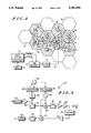
- FIG. 1 is a block diagram of an optical communication downlink embodying the present invention
- FIG. 2 is a system diagram of an optical communication downlink embodying the present invention
- FIGS. 3A-3D are block diagrams of an optical communication uplink embodying the present invention.
- FIG. 4 is a system diagram of an optical communication uplink embodying the present invention.
- FIG. 5 is a block diagram of a cell schematic for use in an optical communication system embodying the present invention.
- FIG. 6 is a block diagram of a relay cell schematic for use in an optical communication system embodying the present invention.
- a distribution network must be established. From a functional standpoint, a tree-branch network would be preferable. This can be accomplished using the tree-branch right-of-ways presently utilized by utility companies.
- downlink 10 utilizes the tree-branch network where optical splitters (13 and 31) are used to branch the optical signal. It should be understood that while dual output splitters are illustrated, there are splitters available which can split an input optical signal into more than two output signals.
- downlink 10 receives a plurality of inputs at a multiplexer 11.
- Input signals received by multiplexer 11 are combined in a Frequency Division Multiplexed (FDM) format and transmitted individually to a transducer 12.
- transducer 12 is a laser and converts an electrical input signal into a light output signal. The light signal is then transmitted to a splitter 13 where it is divided into two or more like signals.
- Each light signal from splitter 13 is then transmitted along an optic conductor to a detector 14.
- Detector 14 receives the optic signal and converts it back to an electrical signal.
- This electrical signal is then forwarded to converter 15.
- Converter 15 consists of a demultiplexer 16 and a filter 17.
- Converter 15 serves to separate a single desired signal from the plurality of signals received at converter 15.
- the filtered signal is then forwarded to a transmitter 18 where it is broadcast to a remote unit using antenna 19.
- the downlink may be expanded to include a second laser 21, shown here receiving an output from detector 14'.
- Laser 21 again converts the signal into an optical signal which is forwarded to detector 22.
- Detector 22 converts the signal back to an electrical signal which is then passed to a transmitter 23 for broadcast using an antenna 24. In this portion of the downlink, the entire signal is broadcast. Therefore, there is no need for a converter similar to converter 15.
- the downlink may be further expanded by adding additional branches. This is represented in FIG. 1 by the inclusion of blocks 30 through 37 and 37'.
- the electrical output signal of detector 14' is converted into an optic signal by laser 30. This signal is then divided in splitter 31. Each of the output signals from splitter 31 is then forwarded to a detector 32 (32'). Detector 32 (32') converts the optic signal back into an electrical signal.
- the electrical signal is then processed in converter 33 (33'), consisting of a demultiplexer 34 (34') and a filter 35 (35').
- the output from converter 33 (33') is then passed to transmitter 36 (36') where it is broadcast using antenna 37 (37').
- the downlink is a tree-branch network design which would be compatible with existing utility company right-of-ways. This is possible through the use of high linearity lasers which can be cascaded two or more times. The ability to cascade the laser signals, as done with splitters 13 and 31, reduces the laser cost by requiring fewer lasers.
- FIG. 2 consists of a plurality of cells, or microcells, 40.
- Cells 40 which are shaded or cross-hatched are served from base station 41.
- Cells 40 which are cross-hatched are relay cells, as will be described below.
- Base station 41 contains a plurality of transceivers n 1 -n x , each capable of handling at least one communication channel.
- Base station 41 is coupled to a switch 42 for directing the input and output connections to transceivers n 1 -n x .
- the input and output to base station 41 from cells 40 is conducted through an FDM converter 43.
- the output of converter 43 is transmitted to a laser 45 where it is converted into an optic signal.
- the optical signal is then transmitted to a splitter 46 along an optical cable 47.
- the optical signal is divided into four equivalent optical signals. Each of the four optical signals is transmitted to one of detectors 48-51 along optic lines 52-55, respectively.
- the signals are reconverted to electrical signals and are generally transmitted to a remote unit, as in FIG. 1.
- the electrical signal from the detector, such as detector 51, may also be forwarded to a laser 56.
- Laser 56 will convert the received electrical signal into an optical signal for transmission over line 57 to splitter 58.
- Splitter 58 once again divides the optical signal into four signals and transmits these signals along optical lines 59-62 to detectors 63-66, respectively.
- Detectors 63-66 will then reconvert the optical signal to an electrical signal for transmission to the remote units, as shown in FIG. 1.
- the base station when the base station is located at the cell site, it must be connected to the switch by backhauling. By allowing the base station to be remoted from the cell site, it can be placed in the same location as the switch, thereby reducing the cost of backhaul to the switch.
- FIGS. 3A-3D block diagrams of various uplink circuits for use in the optical communication system are illustrated.
- a block diagram of an uplink, generally designated 70 is illustrated.
- Uplink 70 shows a pair of transceivers, 71 and 72, which will receive transmitted RF signals. These RF signals are then transmitted to lasers 73 and 74, respectively, where the signals are converted into optical signals.
- optical signals are then transmitted to detectors 76 and 77, respectively, located at a combining station 75.
- the electrical outputs from detectors 76 and 77 are combined in a combiner, such as multiplexer 78.
- the output of multiplexer 78 is transmitted to a laser 79 where the combined electrical signal is converted to an optical signal.
- the output of laser 79 is transmitted to a detector 80 where it is again reconverted to a combined electrical signal.
- the combined electrical signal is then separated in a demultiplexer 81 into its constituent signals which are forwarded to the base station.
- Uplink 90 differs from uplink 70 at the transceiver location. Instead of transceivers 71 and 72 transmitting their received signals directly to the lasers, the signals are first multiplexed in multiplexers 91 and 92, respectively.
- the outputs of multiplexers 91 and 92 are then processed through the lasers (73 and 74) and detectors (76 and 77) as in FIG. 3A. However, since the signals have previously been multiplexed, the outputs from detectors 76 and 77 may be summed in combiner 78', rather than multiplexer 78 (FIG. 3A). The output of combiner 78' is then processed the same as in FIG. 3A.
- Uplink 95 is similar to uplink 90 of FIG. 3B with the exception that detectors 76 and 77 and laser 79 have been eliminated. Rather than converting the optical signals to electrical signals for combining purposes, the optical signals are combined directly in combiner 78'. While this is more difficult to do, it provides a significant savings in the cost of the system by eliminating hardware.
- uplink 95 In FIG. 3D, another example of uplink 95, uplink 95', is illustrated.
- uplink 95' an additional combining station, 96, has been added to the system.
- Combining station 96 is provided to add another input to the signal being processed. This is accomplished by converting the optical inputs to electrical inputs in detectors 97 and 98. These signals are combined in combiner 99 and the combined output is converted to an optical signal by laser 100. The signal is then processed as before.
- FIG. 4 An example of the system uplink is provided in FIG. 4. This system is the same as in FIG. 2 with the uplink shown instead of the downlink.
- RF signals are received at antenna 110-113.
- the signals received in non-relay cells are converted to optic signals in lasers 114-116 for transmission over optic cables 59-61, respectively.
- optical signals are received at the relay cell and reconverted to electrical signals in detectors 117-119. These signals are then combined with the signal received at antenna 113 in a combiner 120. The output from combiner 120 is transmitted to a laser 121 where it is converted to an optical signal and transmitted along optical cable 57 to the next relay cell.
- the signal from laser 121 is then converted back to an electrical signal by a detector 122 where it is combined with other signals received by the relay cell.
- the additional non-relay cell signals are derived from signals received by antenna 123-125. These signals are converted in lasers 127-129 and transmitted to detectors 130-132 along lines 52-54, respectively. These signals are then combined with the signal received by antenna 126 of the relay cell and the signal received at detector 122 in a combiner 133.
- the output of combiner 133 is converted to an optical signal and transmitted to a detector 135 along optic lines 47.
- Detector 135 then reconverts the optical signal to an electrical signal.
- the electrical signal is processed through converter 43 and forwarded to base station 41.
- each cell site contains a single laser. Therefore, for the uplink side of the system, the number of lasers required per cell site is one. Combining this with the number of lasers needed on the downlink side (1/n), and the number of lasers needed for the total system is 1+1/n per cell site. Therefore, by using the tree-branch network method, the required number of lasers is reduced from 2 to 1+1/n per site.
- Cell schematic 150 is for a non-relay cell site and, on the uplink side, consists of an antenna 151 for receiving RF signals. The received signals are transmitted to a pre-amplifier 153 through a duplexer 152.
- pre-amplifier 153 is then mixed with a timing adjustment signal, described below, in a mixer 154.
- the output of mixer 154 is filtered through an FDM filter 155 and converted to an optical signal by laser 156.
- circuit 150 When circuit 150 is in the downlink mode, optical signals are received at detector 157. The optical signal is converted to an electrical signal and amplified in amplifier 158. The output of amplifier 158 is then filtered in an FDM filter 159 and mixed with the timing signal, described below in a mixer 160.
- the corrected output from mixer 160 is then filtered in an FDM filter 161, processed through a low noise amplifier (LNA) 162 and a power amplifier (PA) 163.
- LNA low noise amplifier
- PA power amplifier
- the output of PA 163 is passed through duplexer 152 and broadcast by antenna 151.
- the timing adjustment signal input to mixers 154 and 160 is derived from the input signal.
- the output of amplifier 158 is split and used to drive a pilot signal generator 164.
- the output from pilot signal generator 164 is synthesized in a synthesizer 165 and fed to a reference oscillator 166 which provides feedback to synthesizer 165 and drives a second synthesizer 167.
- the output of synthesizer 167 is then used to control a voltage controlled oscillator (VCO) 168 which provides the timing adjustment signal to mixers 154 and 160.
- VCO voltage controlled oscillator
- FIG. 6 a block diagram of a relay cell schematic, generally designated 150', is illustrated.
- Schematic 150' is similar to schematic 150 with the addition of several other signals received from other remote cells.
- these other signals are to be combined with the signal received at antenna 151. This is accomplished in a combiner 170 after the signals have been converted from optical signals to electrical signals in detectors 171-173.
- the converted signals are then amplified in amplifiers 174-176 before summing with the output of filter 175 in combiner 170.
- the combined signal is then converted in laser 156 and transmitted to the next stage.
- this relay cell may not be the last cell in the downlink distribution. Therefore, the received signal, after being amplified in amplifier 158, is processed through a notch filter 177. The filtered signal is then amplified in an amplifier 178 and converted to an optical signal in a laser 179 before being transmitted to the next stage.
- the above optical distribution system can also serve to reduce the number of transceivers needed in a system.
- Most service providers need to have enough transceivers at a site to handle calls during peak times. That means some transceivers at each site are idle when the system is not at peak loading.
- By colocating the transceivers from various sites into one site excess capacity form one site can be handled by transceivers which would have been at another site. This permits the system provider to use fewer transceivers to handle the same number of system calls.
Abstract
A downlink portion consists of a multiplexer for combining several signals. The combined signal is converted to an optical signal by a laser and transmitted over an optical line to a splitter. The split signals are each transmitted to a detector which converts the optical signals back into an electrical signal. The electrical signal is then filtered to provide the desired signal from the combined signal. The desired signal is then transmitted. The uplink portion consists of a plurality of receivers which receive signals from remote units. The received signals are multiplexed and converted to optical signals in a laser. The optical signals are transmitted over optical lines to a combiner which provides a single combined optical signal. The combined optical signal is then transmitted over optical lines to a detector which converts the optical signals to an electrical signal. The electrical signal is then demultiplexed into its constituent portions.
Description
This is a continuation of application Ser. No. 07/807,317, filed Dec. 16, 1991 and now abandoned.
The present invention relates, in general, to communication systems and, more particularly, to optical distribution systems.
One of the problems facing cellular providers in establishing a cellular communication network, is the cost and acquisition of facilities. Site acquisition for the transmission and switching hardware can account for half or more of the total cost of establishing a new cell site in a metropolitan area.
The present invention provides an optical distribution system which permits multiple cells of a communication network to be covered by one centralized base station.
The downlink portion of the optical distribution system consists of a multiplexing means for combining a plurality of signals into a combined output signal. The combined output signal is forwarded to a first transducer means for converting the combined output signal to an optical signal. The optical signal from the first transducer means is then transmitted over a first optical line to a first splitting means for splitting the optical signal into a plurality of optical signals. Each of the plurality of optical signals are transmitted to a plurality of first detector means over a plurality of second optical links. The first detector means are used to convert the optical signals back into combined signals. Each combined RF signal is then transmitted to one of a plurality of first converting means for isolating a first desired signal from the combined signal. The desired signal is then transmitted using a transmitting means.
The uplink portion of the optical distribution system consists of a plurality of receiving means which receive RF signals from remote units. The received signals are then multiplexed, by either time or frequency, and converted to optical signals in a plurality of lasers. The optical signals are transmitted over optical lines to a combining means which combines the individual optical signals into a single combined optical signal. The combined optical signal is then transmitted over optical lines to a detecting means which converts optical signals to electrical signals. The electrical signal is then demultiplexed into its constituent portions.
In an alternative uplink portion, the individual optical signals may be converted to electrical signals before combining and converted back to optical signals after combining.
In another alternative uplink portion, a single multiplexer may be provided as the combining means. This would eliminate the need for multiplexers coupled to each receiving means and require additional detecting means prior to the multiplexer to convert the optical signals to electrical before multiplexing.
FIG. 1 is a block diagram of an optical communication downlink embodying the present invention;
FIG. 2 is a system diagram of an optical communication downlink embodying the present invention;
FIGS. 3A-3D are block diagrams of an optical communication uplink embodying the present invention;
FIG. 4 is a system diagram of an optical communication uplink embodying the present invention;
FIG. 5 is a block diagram of a cell schematic for use in an optical communication system embodying the present invention; and
FIG. 6 is a block diagram of a relay cell schematic for use in an optical communication system embodying the present invention.
By transporting RF channels from one centralized base station to a group of smaller antenna sites, the cost of the cell site can be reduced. However, once the decision to decentralize has been made, a distribution network must be established. From a functional standpoint, a tree-branch network would be preferable. This can be accomplished using the tree-branch right-of-ways presently utilized by utility companies.
Referring initially to FIG. 1, a block diagram of an optical communication downlink, generally designated 10, is illustrated. As shown, downlink 10 utilizes the tree-branch network where optical splitters (13 and 31) are used to branch the optical signal. It should be understood that while dual output splitters are illustrated, there are splitters available which can split an input optical signal into more than two output signals.
In operation, downlink 10 receives a plurality of inputs at a multiplexer 11. Input signals received by multiplexer 11 are combined in a Frequency Division Multiplexed (FDM) format and transmitted individually to a transducer 12. In the present embodiment, transducer 12 is a laser and converts an electrical input signal into a light output signal. The light signal is then transmitted to a splitter 13 where it is divided into two or more like signals.
Each light signal from splitter 13 is then transmitted along an optic conductor to a detector 14. Detector 14 receives the optic signal and converts it back to an electrical signal. This electrical signal is then forwarded to converter 15. Converter 15 consists of a demultiplexer 16 and a filter 17. Converter 15 serves to separate a single desired signal from the plurality of signals received at converter 15. The filtered signal is then forwarded to a transmitter 18 where it is broadcast to a remote unit using antenna 19.
In addition to the above, the downlink may be expanded to include a second laser 21, shown here receiving an output from detector 14'. Laser 21 again converts the signal into an optical signal which is forwarded to detector 22. Detector 22 converts the signal back to an electrical signal which is then passed to a transmitter 23 for broadcast using an antenna 24. In this portion of the downlink, the entire signal is broadcast. Therefore, there is no need for a converter similar to converter 15.
The downlink may be further expanded by adding additional branches. This is represented in FIG. 1 by the inclusion of blocks 30 through 37 and 37'. The electrical output signal of detector 14' is converted into an optic signal by laser 30. This signal is then divided in splitter 31. Each of the output signals from splitter 31 is then forwarded to a detector 32 (32'). Detector 32 (32') converts the optic signal back into an electrical signal. The electrical signal is then processed in converter 33 (33'), consisting of a demultiplexer 34 (34') and a filter 35 (35'). The output from converter 33 (33') is then passed to transmitter 36 (36') where it is broadcast using antenna 37 (37').
This process may be repeated as long as the quality of the signal is not degraded below a level which would result in an unacceptable communication. As illustrated, the downlink is a tree-branch network design which would be compatible with existing utility company right-of-ways. This is possible through the use of high linearity lasers which can be cascaded two or more times. The ability to cascade the laser signals, as done with splitters 13 and 31, reduces the laser cost by requiring fewer lasers.
The number of lasers on the downlink side per site can be as few as 1/n where n is the number of split signals produces by the splitters. This assumes that each splitter produces the same number of outputs. With splitters providing two output signals (n=2), the above equation would result in 0.5 lasers required per site. As shown in FIG. 1, discounting laser 21 as a special case, there are four cell sites (19, 19', 37, and 37') served by two lasers (12 and 30), or 0.5 lasers per site.
Another example of the system downlink is provided in FIG. 2. FIG. 2 consists of a plurality of cells, or microcells, 40. Cells 40 which are shaded or cross-hatched are served from base station 41. Cells 40 which are cross-hatched are relay cells, as will be described below. Base station 41 contains a plurality of transceivers n1 -nx, each capable of handling at least one communication channel. Base station 41 is coupled to a switch 42 for directing the input and output connections to transceivers n1 -nx.
The input and output to base station 41 from cells 40 is conducted through an FDM converter 43. For the downlink portion, the output of converter 43 is transmitted to a laser 45 where it is converted into an optic signal. The optical signal is then transmitted to a splitter 46 along an optical cable 47. At splitter 47, the optical signal is divided into four equivalent optical signals. Each of the four optical signals is transmitted to one of detectors 48-51 along optic lines 52-55, respectively.
At detectors 48-51, the signals are reconverted to electrical signals and are generally transmitted to a remote unit, as in FIG. 1. The electrical signal from the detector, such as detector 51, may also be forwarded to a laser 56. Laser 56 will convert the received electrical signal into an optical signal for transmission over line 57 to splitter 58. Splitter 58 once again divides the optical signal into four signals and transmits these signals along optical lines 59-62 to detectors 63-66, respectively. Detectors 63-66 will then reconvert the optical signal to an electrical signal for transmission to the remote units, as shown in FIG. 1.
In the example of FIG. 2, the splitters are providing four output signals (n=4), which means that 0.25 (1/n) lasers are needed per cell site, on the downlink portion of the system. This is supported by FIG. 2 in that only 2 lasers are required to supply 8 cell sites, or 0.25 lasers per cell site.
In addition, when the base station is located at the cell site, it must be connected to the switch by backhauling. By allowing the base station to be remoted from the cell site, it can be placed in the same location as the switch, thereby reducing the cost of backhaul to the switch.
Referring now to FIGS. 3A-3D, block diagrams of various uplink circuits for use in the optical communication system are illustrated. In FIG. 3A, a block diagram of an uplink, generally designated 70, is illustrated. Uplink 70 shows a pair of transceivers, 71 and 72, which will receive transmitted RF signals. These RF signals are then transmitted to lasers 73 and 74, respectively, where the signals are converted into optical signals.
The optical signals are then transmitted to detectors 76 and 77, respectively, located at a combining station 75. At station 75, the electrical outputs from detectors 76 and 77 are combined in a combiner, such as multiplexer 78. The output of multiplexer 78 is transmitted to a laser 79 where the combined electrical signal is converted to an optical signal.
The output of laser 79 is transmitted to a detector 80 where it is again reconverted to a combined electrical signal. The combined electrical signal is then separated in a demultiplexer 81 into its constituent signals which are forwarded to the base station.
Referring now to FIG. 3B, a block diagram of a second uplink, generally designated 90, is illustrated. Uplink 90 differs from uplink 70 at the transceiver location. Instead of transceivers 71 and 72 transmitting their received signals directly to the lasers, the signals are first multiplexed in multiplexers 91 and 92, respectively.
The outputs of multiplexers 91 and 92 are then processed through the lasers (73 and 74) and detectors (76 and 77) as in FIG. 3A. However, since the signals have previously been multiplexed, the outputs from detectors 76 and 77 may be summed in combiner 78', rather than multiplexer 78 (FIG. 3A). The output of combiner 78' is then processed the same as in FIG. 3A.
Referring now to FIG. 3C, a block diagram of a third uplink, generally designated 95, is illustrated. Uplink 95 is similar to uplink 90 of FIG. 3B with the exception that detectors 76 and 77 and laser 79 have been eliminated. Rather than converting the optical signals to electrical signals for combining purposes, the optical signals are combined directly in combiner 78'. While this is more difficult to do, it provides a significant savings in the cost of the system by eliminating hardware.
In FIG. 3D, another example of uplink 95, uplink 95', is illustrated. In uplink 95' an additional combining station, 96, has been added to the system. Combining station 96 is provided to add another input to the signal being processed. This is accomplished by converting the optical inputs to electrical inputs in detectors 97 and 98. These signals are combined in combiner 99 and the combined output is converted to an optical signal by laser 100. The signal is then processed as before.
An example of the system uplink is provided in FIG. 4. This system is the same as in FIG. 2 with the uplink shown instead of the downlink. In the system, RF signals are received at antenna 110-113. The signals received in non-relay cells are converted to optic signals in lasers 114-116 for transmission over optic cables 59-61, respectively.
The optical signals are received at the relay cell and reconverted to electrical signals in detectors 117-119. These signals are then combined with the signal received at antenna 113 in a combiner 120. The output from combiner 120 is transmitted to a laser 121 where it is converted to an optical signal and transmitted along optical cable 57 to the next relay cell.
The signal from laser 121 is then converted back to an electrical signal by a detector 122 where it is combined with other signals received by the relay cell. The additional non-relay cell signals are derived from signals received by antenna 123-125. These signals are converted in lasers 127-129 and transmitted to detectors 130-132 along lines 52-54, respectively. These signals are then combined with the signal received by antenna 126 of the relay cell and the signal received at detector 122 in a combiner 133.
The output of combiner 133 is converted to an optical signal and transmitted to a detector 135 along optic lines 47. Detector 135 then reconverts the optical signal to an electrical signal. The electrical signal is processed through converter 43 and forwarded to base station 41.
As illustrated in FIG. 4, each cell site contains a single laser. Therefore, for the uplink side of the system, the number of lasers required per cell site is one. Combining this with the number of lasers needed on the downlink side (1/n), and the number of lasers needed for the total system is 1+1/n per cell site. Therefore, by using the tree-branch network method, the required number of lasers is reduced from 2 to 1+1/n per site.
One method of implementing the present invention at a cell site is represented in the block diagram of a cell schematic, generally designated 150, of FIG. 5. Cell schematic 150 is for a non-relay cell site and, on the uplink side, consists of an antenna 151 for receiving RF signals. The received signals are transmitted to a pre-amplifier 153 through a duplexer 152.
The output of pre-amplifier 153 is then mixed with a timing adjustment signal, described below, in a mixer 154. The output of mixer 154 is filtered through an FDM filter 155 and converted to an optical signal by laser 156.
When circuit 150 is in the downlink mode, optical signals are received at detector 157. The optical signal is converted to an electrical signal and amplified in amplifier 158. The output of amplifier 158 is then filtered in an FDM filter 159 and mixed with the timing signal, described below in a mixer 160.
The corrected output from mixer 160 is then filtered in an FDM filter 161, processed through a low noise amplifier (LNA) 162 and a power amplifier (PA) 163. The output of PA 163 is passed through duplexer 152 and broadcast by antenna 151.
The timing adjustment signal input to mixers 154 and 160 is derived from the input signal. The output of amplifier 158 is split and used to drive a pilot signal generator 164. The output from pilot signal generator 164 is synthesized in a synthesizer 165 and fed to a reference oscillator 166 which provides feedback to synthesizer 165 and drives a second synthesizer 167. The output of synthesizer 167 is then used to control a voltage controlled oscillator (VCO) 168 which provides the timing adjustment signal to mixers 154 and 160.
Referring now to FIG. 6, a block diagram of a relay cell schematic, generally designated 150', is illustrated. Schematic 150' is similar to schematic 150 with the addition of several other signals received from other remote cells. In the uplink side of the system, these other signals are to be combined with the signal received at antenna 151. This is accomplished in a combiner 170 after the signals have been converted from optical signals to electrical signals in detectors 171-173. The converted signals are then amplified in amplifiers 174-176 before summing with the output of filter 175 in combiner 170. The combined signal is then converted in laser 156 and transmitted to the next stage.
In addition, this relay cell may not be the last cell in the downlink distribution. Therefore, the received signal, after being amplified in amplifier 158, is processed through a notch filter 177. The filtered signal is then amplified in an amplifier 178 and converted to an optical signal in a laser 179 before being transmitted to the next stage.
The above optical distribution system can also serve to reduce the number of transceivers needed in a system. Most service providers need to have enough transceivers at a site to handle calls during peak times. That means some transceivers at each site are idle when the system is not at peak loading. By colocating the transceivers from various sites into one site, excess capacity form one site can be handled by transceivers which would have been at another site. This permits the system provider to use fewer transceivers to handle the same number of system calls.
Thus, it will be apparent to one skilled in the art that there has been provided in accordance with the invention, an optical distribution system that fully satisfies the objects, aims, and advantages set forth above.
While the invention has been described in conjunction with specific embodiments thereof, it is evident that many alterations, modifications, and variations will be apparent to those skilled in the art in light of the foregoing description. Accordingly, it is intended to embrace all such alterations, modifications, and variations in the appended claims.
Claims (19)
1. An optical distribution system having a downlink portion and an uplink portion, said downlink portion comprising:
multiplexing means for combining a plurality of RF signals into a combined RF output signal;
first transducer means for converting said combined RF output signal to an optical signal;
a first optical link having a first end coupled to receive said optic signal;
first splitting means for splitting said optic signal into a plurality of optic signals, said first splitting means having an input coupled to a second end of said first optical link and a plurality of outputs;
a plurality of second optical links each having a first end coupled to one of said plurality of outputs of said first splitting means and a second end;
a plurality of first detector means for converting one of said plurality of optic signals back into said combined RF signal, each of said plurality of first detector means having an input coupled to a second end of one of said plurality of second optical links and an output;
a plurality of first converting means for isolating a first desired RF signal from said combined RF signal, each of said plurality of first converting means having an input coupled to said output of one of said plurality of first detector means;
a plurality of first transmitting means each coupled to said output of one of said plurality of first converting means for transmitting said desired RF signals;
second transducer means converting said combined RF signal into a second optic signal, said second transducer means having an input coupled to said output of one of said plurality of detector means;
second detector means for converting said second optic signal back into said combined RF signal, said second detector means having an input coupled to an output of said second transducer means;
second converting means for isolating a second desired RF signal from said combined RF signals, said second converting means having an input coupled to an output of said second detector means; and
second transmitting means for transmitting said second desired RF signal, said second transmitting means having an input coupled to an output of said second converting means.
2. The downlink portion of the optical distribution system of claim 1 wherein said multiplexing means is a time multiplexing means.
3. The downlink portion of the optical distribution system of claim 1 wherein said multiplexing means is a frequency multiplexing means.
4. The downlink portion of the optical distribution system of claim 1 wherein said first optical link and said plurality of second optical links are each a fiber optic cable.
5. The downlink portion of the optical distribution system of claim 1 wherein said each of said plurality of first converting means comprises:
demultiplexing means for dividing said combined RF signal into a plurality of individual RF signals; and
filter means for filtering one of said individual RF signals to provide said desired RF signal.
6. The downlink portion of the optical distribution system of claim 5 wherein said demultiplexing means is a selective demultiplexing means.
7. The downlink portion of the optical distribution system of claim 1 wherein each of said plurality of first transmitting means comprises an antenna.
8. The downlink portion of the optical distribution system of claim 1 further comprising:
second transducer means converting said combined RF signal into a second optic signal, said second transducer means having an input coupled to said output of one of said plurality of detector means;
second splitting means for splitting said optic signal into a plurality of optic signals, said first splitting means having an input coupled to said second end of said first optical link and a plurality of outputs;
a plurality of third optical links each having a first end coupled to one of said plurality of outputs of said second splitting means and a second end;
a plurality of second detector means for converting one of said plurality of optic signals back into said combined RF signal, each of said plurality of second detector means having an input coupled to a second end of one of said plurality of third optical links and an output;
a plurality of second converting means for isolating a second desired RF signal from said combined RF signal, each of said plurality of second converting means having an input coupled to said output of one of said plurality of second detector means; and
a plurality of second transmitting means each coupled to said output of one of said plurality of second converting means for transmitting said desired RF signals.
9. An optical distribution system having a downlink portion and an uplink portion, said uplink portion comprising:
a plurality of first receiving means for receiving an RF signal; p1 a plurality of multiplexing means for multiplexing each received RF signal, each having an input coupled to an output of one of said plurality of first receiving means;
a plurality of first transducer means for converting each multiplexed RF signal to an optical signal, each first transducer means having an input coupled to an output of one of said plurality of multiplexing means;
a plurality of first optical links, each having a first end coupled to an output of one of said plurality of transducer means and a second end;
a plurality of first detecting means for converting each optical signal to an electrical signal, each having an input coupled to said second end of one of said plurality of first optical links and each having an output;
combining means for combining a plurality of input signals and producing an output signal, said combining means having a plurality of inputs, each coupled to one of said outputs of said plurality of first detecting means;
second transducer means for converting an electrical signal to an optical signal, said second transducer means having an input coupled to an output of said combining means;
a second optical link having a first end coupled to an output of said second transducer means and a second end;
second detecting means for converting an optical signal to an electrical signal, said second detecting means having an input coupled to said second end of said second optical link; and
demultiplexing means for demultiplexing a received signal into a plurality of output signals, said demultiplexing means having an input coupled to an output of said second detecting means and an output.
10. The uplink portion of the optical distribution system of claim 9 wherein said plurality of first optical links and said second optical link are each a fiber optic cable.
11. The uplink portion of the optical distribution system of claim 9 wherein said plurality of first transducer means each comprises a laser.
12. The uplink portion of the optical distribution system of claim 9 wherein said plurality of multiplexing means are each a time multiplexing means.
13. The uplink portion of the optical distribution system of claim 9 wherein said plurality of multiplexing means are each a frequency multiplexing means.
14. An optical distribution system having an uplink portion, downlink portion and a transceiver, said transceiver comprising:
antenna means for one of receiving and transmitting an RF signal;
duplexing means coupled to said antenna for one of coupling a downlink signal received from said downlink portion to said antenna and coupling an uplink signal received form said antenna to said uplink portion, said duplex means having an input and an output;
first mixing means for combining said uplink signal with a timing adjustment signal, said first mixing means having a first input coupled to said output of said duplexing means, a second input coupled to receive said timing adjustment means, and an output;
first transducer means for converting an electrical signal to an optical signal, said first transducer means having an input coupled to said output of said first mixing means and an output coupled to said uplink portion;
first detector means for converting an optical signal to an electrical signal, said first detector means having an input coupled to said downlink portion and an output; and
second mixing means for combining said downlink signal with said timing adjustment signal, said second mixing means having a first input coupled to said output of said first detector means, a second input coupled to receive said timing adjustment signal, and an output coupled to said input of said duplexing means.
15. The transceiver of the optical distribution system of claim 14 further comprising:
a pre-amplifier having an input coupled to said output of said duplexer and an output coupled to said first input of said first mixing means; and
filter means for filtering a signal, said filter means having an input coupled to said output of said first mixing means and an output coupled to said input of said first transducer means.
16. The transceiver of the optical distribution system of claim 14 further comprising:
first filter means for filtering a signal, said first filter means having an input coupled to said output of said first detector means and an output coupled to said first input of said second mixing means;
second filter means for filtering a signal, said first filter means having an input coupled to said output of said second mixing means and an output;
a low noise amplifier having an input coupled to said output of said second filter means and an output; and
a power amplifier having an input coupled to said output of said low noise amplifier and an output coupled to said input of said duplexing means.
17. The transceiver of the optical distribution system of claim 14 further comprising:
a pilot having an input coupled to said output of said first detector means and an output;
first synthesizer means for synthesizing a signal, said first synthesizer means having an input coupled to said output of said pilot, an output, and a feedback input;
oscillator means for providing an oscillating signal, said oscillator means having an input coupled to said output of said first synthesizer, a feedback output coupled to said feedback input of said first synthesizer, and an output;
second synthesizer means for synthesizing a signal, said second synthesizer means having an input coupled to said output of said oscillating means and an output; and
a voltage controlled oscillator having an input coupled to said output of said second synthesizer and an output coupled to said second inputs of said first and second mixing means.
18. The transceiver of the optical distribution system of claim 14 further comprising:
summing means for combining a plurality of signals, said summing means having a first input coupled to said output of said first mixing means, a second input, and an output coupled to said input of said first transducer means; and
second detector means for converting an optical signal to an electrical signal, said second detector having an output coupled to said second input of said summing means.
19. The transceiver of the optical distribution system of claim 14 further comprising:
a notch filter having an input coupled to said output of said first detector means and an output; and
second transducer means for converting an electrical signal to an optical signal, said second transducer having an input coupled to said output of said notch filter.
Priority Applications (1)
| Application Number | Priority Date | Filing Date | Title |
|---|---|---|---|
| US08/107,046 US5301056A (en) | 1991-12-16 | 1993-08-16 | Optical distribution system |
Applications Claiming Priority (2)
| Application Number | Priority Date | Filing Date | Title |
|---|---|---|---|
| US80731791A | 1991-12-16 | 1991-12-16 | |
| US08/107,046 US5301056A (en) | 1991-12-16 | 1993-08-16 | Optical distribution system |
Related Parent Applications (1)
| Application Number | Title | Priority Date | Filing Date |
|---|---|---|---|
| US80731791A Continuation | 1991-12-16 | 1991-12-16 |
Publications (1)
| Publication Number | Publication Date |
|---|---|
| US5301056A true US5301056A (en) | 1994-04-05 |
Family
ID=25196088
Family Applications (2)
| Application Number | Title | Priority Date | Filing Date |
|---|---|---|---|
| US08/099,641 Expired - Fee Related US5375007A (en) | 1991-12-16 | 1993-07-30 | Optical distribution system |
| US08/107,046 Expired - Lifetime US5301056A (en) | 1991-12-16 | 1993-08-16 | Optical distribution system |
Family Applications Before (1)
| Application Number | Title | Priority Date | Filing Date |
|---|---|---|---|
| US08/099,641 Expired - Fee Related US5375007A (en) | 1991-12-16 | 1993-07-30 | Optical distribution system |
Country Status (5)
| Country | Link |
|---|---|
| US (2) | US5375007A (en) |
| FR (1) | FR2686203A1 (en) |
| GB (1) | GB2268653B (en) |
| HK (1) | HK1000619A1 (en) |
| WO (1) | WO1993012596A1 (en) |
Cited By (72)
| Publication number | Priority date | Publication date | Assignee | Title |
|---|---|---|---|---|
| US5615034A (en) * | 1994-11-25 | 1997-03-25 | Nec Corporation | Optical micro cell transmission system |
| US5627879A (en) * | 1992-09-17 | 1997-05-06 | Adc Telecommunications, Inc. | Cellular communications system with centralized base stations and distributed antenna units |
| US5844705A (en) * | 1997-02-13 | 1998-12-01 | At&T Corp | Wireless communications systems employing free-space optical communications links |
| US5859854A (en) * | 1995-08-28 | 1999-01-12 | Metawave Communications Corporation | System and method for frequency multiplexing antenna signals |
| US6112086A (en) * | 1997-02-25 | 2000-08-29 | Adc Telecommunications, Inc. | Scanning RSSI receiver system using inverse fast fourier transforms for a cellular communications system with centralized base stations and distributed antenna units |
| US6704298B1 (en) * | 1998-09-11 | 2004-03-09 | Kokusai Electric Co., Ltd. | Repeater amplifier apparatus |
| US20040106435A1 (en) * | 2002-12-03 | 2004-06-03 | Adc Telecommunications, Inc. | Distributed digital antenna system |
| US20040203704A1 (en) * | 2002-06-10 | 2004-10-14 | Andrew Corporation | Indoor wireless voice and data distribution system |
| US20070248358A1 (en) * | 2006-04-19 | 2007-10-25 | Michael Sauer | Electrical-optical cable for wireless systems |
| US20070257796A1 (en) * | 2006-05-08 | 2007-11-08 | Easton Martyn N | Wireless picocellular RFID systems and methods |
| US20070269170A1 (en) * | 2006-05-19 | 2007-11-22 | Easton Martyn N | Fiber optic cable and fiber optic cable assembly for wireless access |
| US20070292137A1 (en) * | 2006-06-16 | 2007-12-20 | Michael Sauer | Redundant transponder array for a radio-over-fiber optical fiber cable |
| US20080044186A1 (en) * | 2006-08-16 | 2008-02-21 | Jacob George | Radio-over-fiber transponder with a dual-band patch antenna system |
| US20080070502A1 (en) * | 2006-09-15 | 2008-03-20 | Jacob George | Radio-over-fiber (RoF) optical fiber cable system with transponder diversity and RoF wireless picocellular system using same |
| US20080080863A1 (en) * | 2006-09-28 | 2008-04-03 | Michael Sauer | Radio-over-fiber (RoF) wireless picocellular system with combined picocells |
| US20080186143A1 (en) * | 2007-02-06 | 2008-08-07 | Jacob George | Transponder systems and methods for radio-over-fiber (ROF) wireless picocellular systems |
| US20080232305A1 (en) * | 2006-12-19 | 2008-09-25 | Yair Oren | Distributed Antenna System for MIMO Technologies |
| US20090176448A1 (en) * | 2002-02-25 | 2009-07-09 | Adc Telecommunications, Inc. | Distributed automatic gain control system |
| US7599711B2 (en) | 2006-04-12 | 2009-10-06 | Adc Telecommunications, Inc. | Systems and methods for analog transport of RF voice/data communications |
| US20110200325A1 (en) * | 2010-02-15 | 2011-08-18 | Andrey Kobyakov | Dynamic Cell Bonding (DCB) for Radio-over-Fiber (RoF)-Based Networks and Communication Systems and Related Methods |
| US8175459B2 (en) | 2007-10-12 | 2012-05-08 | Corning Cable Systems Llc | Hybrid wireless/wired RoF transponder and hybrid RoF communication system using same |
| US8548330B2 (en) | 2009-07-31 | 2013-10-01 | Corning Cable Systems Llc | Sectorization in distributed antenna systems, and related components and methods |
| US20130260706A1 (en) * | 2012-03-27 | 2013-10-03 | Lgc Wireless, Llc | Systems and methods for implementing a distributed antenna system in a radio frequency integrated circuit |
| US8583100B2 (en) | 2007-01-25 | 2013-11-12 | Adc Telecommunications, Inc. | Distributed remote base station system |
| US8644844B2 (en) | 2007-12-20 | 2014-02-04 | Corning Mobileaccess Ltd. | Extending outdoor location based services and applications into enclosed areas |
| US8737454B2 (en) | 2007-01-25 | 2014-05-27 | Adc Telecommunications, Inc. | Modular wireless communications platform |
| US8867919B2 (en) | 2007-07-24 | 2014-10-21 | Corning Cable Systems Llc | Multi-port accumulator for radio-over-fiber (RoF) wireless picocellular systems |
| US8902812B1 (en) * | 2006-03-14 | 2014-12-02 | Sprint Spectrum L.P. | System and method for passive optical network backhaul |
| US9001811B2 (en) | 2009-05-19 | 2015-04-07 | Adc Telecommunications, Inc. | Method of inserting CDMA beacon pilots in output of distributed remote antenna nodes |
| US9037143B2 (en) | 2010-08-16 | 2015-05-19 | Corning Optical Communications LLC | Remote antenna clusters and related systems, components, and methods supporting digital data signal propagation between remote antenna units |
| US9042732B2 (en) | 2010-05-02 | 2015-05-26 | Corning Optical Communications LLC | Providing digital data services in optical fiber-based distributed radio frequency (RF) communication systems, and related components and methods |
| US9112611B2 (en) | 2009-02-03 | 2015-08-18 | Corning Optical Communications LLC | Optical fiber-based distributed antenna systems, components, and related methods for calibration thereof |
| US9178635B2 (en) | 2014-01-03 | 2015-11-03 | Corning Optical Communications Wireless Ltd | Separation of communication signal sub-bands in distributed antenna systems (DASs) to reduce interference |
| US9184843B2 (en) | 2011-04-29 | 2015-11-10 | Corning Optical Communications LLC | Determining propagation delay of communications in distributed antenna systems, and related components, systems, and methods |
| US9219879B2 (en) | 2009-11-13 | 2015-12-22 | Corning Optical Communications LLC | Radio-over-fiber (ROF) system for protocol-independent wired and/or wireless communication |
| US9240835B2 (en) | 2011-04-29 | 2016-01-19 | Corning Optical Communications LLC | Systems, methods, and devices for increasing radio frequency (RF) power in distributed antenna systems |
| US9247543B2 (en) | 2013-07-23 | 2016-01-26 | Corning Optical Communications Wireless Ltd | Monitoring non-supported wireless spectrum within coverage areas of distributed antenna systems (DASs) |
| US9258052B2 (en) | 2012-03-30 | 2016-02-09 | Corning Optical Communications LLC | Reducing location-dependent interference in distributed antenna systems operating in multiple-input, multiple-output (MIMO) configuration, and related components, systems, and methods |
| US9325429B2 (en) | 2011-02-21 | 2016-04-26 | Corning Optical Communications LLC | Providing digital data services as electrical signals and radio-frequency (RF) communications over optical fiber in distributed communications systems, and related components and methods |
| US9357551B2 (en) | 2014-05-30 | 2016-05-31 | Corning Optical Communications Wireless Ltd | Systems and methods for simultaneous sampling of serial digital data streams from multiple analog-to-digital converters (ADCS), including in distributed antenna systems |
| US9385810B2 (en) | 2013-09-30 | 2016-07-05 | Corning Optical Communications Wireless Ltd | Connection mapping in distributed communication systems |
| US9420542B2 (en) | 2014-09-25 | 2016-08-16 | Corning Optical Communications Wireless Ltd | System-wide uplink band gain control in a distributed antenna system (DAS), based on per band gain control of remote uplink paths in remote units |
| US9455784B2 (en) | 2012-10-31 | 2016-09-27 | Corning Optical Communications Wireless Ltd | Deployable wireless infrastructures and methods of deploying wireless infrastructures |
| US9525472B2 (en) | 2014-07-30 | 2016-12-20 | Corning Incorporated | Reducing location-dependent destructive interference in distributed antenna systems (DASS) operating in multiple-input, multiple-output (MIMO) configuration, and related components, systems, and methods |
| US9525488B2 (en) | 2010-05-02 | 2016-12-20 | Corning Optical Communications LLC | Digital data services and/or power distribution in optical fiber-based distributed communications systems providing digital data and radio frequency (RF) communications services, and related components and methods |
| US9531452B2 (en) | 2012-11-29 | 2016-12-27 | Corning Optical Communications LLC | Hybrid intra-cell / inter-cell remote unit antenna bonding in multiple-input, multiple-output (MIMO) distributed antenna systems (DASs) |
| US9577922B2 (en) | 2014-02-18 | 2017-02-21 | Commscope Technologies Llc | Selectively combining uplink signals in distributed antenna systems |
| US9602210B2 (en) | 2014-09-24 | 2017-03-21 | Corning Optical Communications Wireless Ltd | Flexible head-end chassis supporting automatic identification and interconnection of radio interface modules and optical interface modules in an optical fiber-based distributed antenna system (DAS) |
| US9621293B2 (en) | 2012-08-07 | 2017-04-11 | Corning Optical Communications Wireless Ltd | Distribution of time-division multiplexed (TDM) management services in a distributed antenna system, and related components, systems, and methods |
| US9647758B2 (en) | 2012-11-30 | 2017-05-09 | Corning Optical Communications Wireless Ltd | Cabling connectivity monitoring and verification |
| US9661781B2 (en) | 2013-07-31 | 2017-05-23 | Corning Optical Communications Wireless Ltd | Remote units for distributed communication systems and related installation methods and apparatuses |
| US9673904B2 (en) | 2009-02-03 | 2017-06-06 | Corning Optical Communications LLC | Optical fiber-based distributed antenna systems, components, and related methods for calibration thereof |
| US9681313B2 (en) | 2015-04-15 | 2017-06-13 | Corning Optical Communications Wireless Ltd | Optimizing remote antenna unit performance using an alternative data channel |
| US9715157B2 (en) | 2013-06-12 | 2017-07-25 | Corning Optical Communications Wireless Ltd | Voltage controlled optical directional coupler |
| US9729267B2 (en) | 2014-12-11 | 2017-08-08 | Corning Optical Communications Wireless Ltd | Multiplexing two separate optical links with the same wavelength using asymmetric combining and splitting |
| US9730228B2 (en) | 2014-08-29 | 2017-08-08 | Corning Optical Communications Wireless Ltd | Individualized gain control of remote uplink band paths in a remote unit in a distributed antenna system (DAS), based on combined uplink power level in the remote unit |
| US9775123B2 (en) | 2014-03-28 | 2017-09-26 | Corning Optical Communications Wireless Ltd. | Individualized gain control of uplink paths in remote units in a distributed antenna system (DAS) based on individual remote unit contribution to combined uplink power |
| US9807700B2 (en) | 2015-02-19 | 2017-10-31 | Corning Optical Communications Wireless Ltd | Offsetting unwanted downlink interference signals in an uplink path in a distributed antenna system (DAS) |
| US9948349B2 (en) | 2015-07-17 | 2018-04-17 | Corning Optical Communications Wireless Ltd | IOT automation and data collection system |
| US9974074B2 (en) | 2013-06-12 | 2018-05-15 | Corning Optical Communications Wireless Ltd | Time-division duplexing (TDD) in distributed communications systems, including distributed antenna systems (DASs) |
| US10096909B2 (en) | 2014-11-03 | 2018-10-09 | Corning Optical Communications Wireless Ltd. | Multi-band monopole planar antennas configured to facilitate improved radio frequency (RF) isolation in multiple-input multiple-output (MIMO) antenna arrangement |
| US10110308B2 (en) | 2014-12-18 | 2018-10-23 | Corning Optical Communications Wireless Ltd | Digital interface modules (DIMs) for flexibly distributing digital and/or analog communications signals in wide-area analog distributed antenna systems (DASs) |
| US10128951B2 (en) | 2009-02-03 | 2018-11-13 | Corning Optical Communications LLC | Optical fiber-based distributed antenna systems, components, and related methods for monitoring and configuring thereof |
| US10135533B2 (en) | 2014-11-13 | 2018-11-20 | Corning Optical Communications Wireless Ltd | Analog distributed antenna systems (DASS) supporting distribution of digital communications signals interfaced from a digital signal source and analog radio frequency (RF) communications signals |
| US10136200B2 (en) | 2012-04-25 | 2018-11-20 | Corning Optical Communications LLC | Distributed antenna system architectures |
| US10187151B2 (en) | 2014-12-18 | 2019-01-22 | Corning Optical Communications Wireless Ltd | Digital-analog interface modules (DAIMs) for flexibly distributing digital and/or analog communications signals in wide-area analog distributed antenna systems (DASs) |
| US10236924B2 (en) | 2016-03-31 | 2019-03-19 | Corning Optical Communications Wireless Ltd | Reducing out-of-channel noise in a wireless distribution system (WDS) |
| US10499269B2 (en) | 2015-11-12 | 2019-12-03 | Commscope Technologies Llc | Systems and methods for assigning controlled nodes to channel interfaces of a controller |
| US10498434B2 (en) | 2000-07-19 | 2019-12-03 | CommScope Technolgies LLC | Point-to-multipoint digital radio frequency transport |
| US10560214B2 (en) | 2015-09-28 | 2020-02-11 | Corning Optical Communications LLC | Downlink and uplink communication path switching in a time-division duplex (TDD) distributed antenna system (DAS) |
| US10659163B2 (en) | 2014-09-25 | 2020-05-19 | Corning Optical Communications LLC | Supporting analog remote antenna units (RAUs) in digital distributed antenna systems (DASs) using analog RAU digital adaptors |
| US11178609B2 (en) | 2010-10-13 | 2021-11-16 | Corning Optical Communications LLC | Power management for remote antenna units in distributed antenna systems |
Families Citing this family (6)
| Publication number | Priority date | Publication date | Assignee | Title |
|---|---|---|---|---|
| US5450223A (en) * | 1993-09-07 | 1995-09-12 | Martin Marietta Corp. | Optical demultiplexer for optical/RF signals |
| NL9500113A (en) * | 1995-01-23 | 1996-09-02 | Nederland Ptt | Transmission system. |
| IL114176A (en) * | 1995-06-15 | 2000-02-29 | Jolt Ltd | Wireless communication system |
| US5809422A (en) * | 1996-03-08 | 1998-09-15 | Watkins Johnson Company | Distributed microcellular communications system |
| GB2370170B (en) * | 2000-12-15 | 2003-01-29 | Ntl Group Ltd | Signal transmission systems |
| JP2002185490A (en) * | 2000-12-19 | 2002-06-28 | Denso Corp | Communication system and terminal apparatus |
Citations (10)
| Publication number | Priority date | Publication date | Assignee | Title |
|---|---|---|---|---|
| US4630254A (en) * | 1984-10-26 | 1986-12-16 | Trw Inc. | Controlled star network |
| US4726010A (en) * | 1985-02-28 | 1988-02-16 | Standard Elektrik Lorenz Ag | Optical communication system in the subscriber loop |
| US4821255A (en) * | 1987-05-06 | 1989-04-11 | Bell Communications Research, Inc. | Cross-connection of wavelength-division-multiplexed high speed optical channels |
| US4831616A (en) * | 1987-03-31 | 1989-05-16 | Huber David R | Multiplexed fiber optics wideband data distribution system |
| US4916460A (en) * | 1988-01-29 | 1990-04-10 | Decibel Products, Incorporated | Distributed antenna system |
| JPH02162857A (en) * | 1988-12-15 | 1990-06-22 | Hamamatsu Photonics Kk | Communication method using light and radio wave |
| US5005936A (en) * | 1990-05-22 | 1991-04-09 | Hughes Aircraft Company | Long range bidirectional optical fiber communication link |
| US5060302A (en) * | 1990-02-28 | 1991-10-22 | At&T Bell Laboratories | Automatic adjustment of optical power output of a plurality of optical transmitters |
| US5073982A (en) * | 1989-09-01 | 1991-12-17 | General Electric Company | Apparatus for connecting multiple passive stars in a fiber optic network |
| US5159479A (en) * | 1988-06-17 | 1992-10-27 | Small Power Communication Systems Research Laboratories Co., Ltd. | Private branch radio communication system using optical fibers |
Family Cites Families (11)
| Publication number | Priority date | Publication date | Assignee | Title |
|---|---|---|---|---|
| DE2943867A1 (en) * | 1979-10-30 | 1981-05-07 | Siemens AG, 1000 Berlin und 8000 München | TELEPHONE PARTNER STATION |
| JPS59194541A (en) * | 1983-04-19 | 1984-11-05 | Matsushita Electric Ind Co Ltd | Transmitting device of optical space |
| GB2155718B (en) * | 1984-03-08 | 1987-01-28 | Standard Telephones Cables Ltd | Local area network |
| US5081706A (en) * | 1987-07-30 | 1992-01-14 | Texas Instruments Incorporated | Broadband merged switch |
| FR2622754B1 (en) * | 1987-10-29 | 1990-01-12 | Alcatel Espace | RADIO-OPTICAL TRANSMISSION SYSTEM, ESPECIALLY IN THE FIELD OF SPATIAL TELECOMMUNICATIONS |
| GB8826476D0 (en) * | 1988-11-11 | 1988-12-14 | British Telecomm | Communications system |
| US5010346A (en) * | 1989-10-27 | 1991-04-23 | The Boeing Company | Electro-optical analog-to-digital converter and method for digitizing an analog signal |
| NO910261L (en) * | 1990-02-01 | 1991-08-02 | Alcatel Nv | MOBILE RADIO SYSTEM. |
| JPH03283725A (en) * | 1990-03-30 | 1991-12-13 | Nippon Telegr & Teleph Corp <Ntt> | Radio communication system |
| US5142551A (en) * | 1991-02-28 | 1992-08-25 | Motorola, Inc. | Signal weighting system for digital receiver |
| US5175872A (en) * | 1991-03-28 | 1992-12-29 | Motorola, Inc. | Combined trunked/cellular communication unit |
-
1992
- 1992-10-05 WO PCT/US1992/008438 patent/WO1993012596A1/en active Application Filing
- 1992-10-05 GB GB9315239A patent/GB2268653B/en not_active Expired - Fee Related
- 1992-12-16 FR FR9215187A patent/FR2686203A1/en active Granted
-
1993
- 1993-07-30 US US08/099,641 patent/US5375007A/en not_active Expired - Fee Related
- 1993-08-16 US US08/107,046 patent/US5301056A/en not_active Expired - Lifetime
-
1997
- 1997-11-19 HK HK97102195A patent/HK1000619A1/en not_active IP Right Cessation
Patent Citations (10)
| Publication number | Priority date | Publication date | Assignee | Title |
|---|---|---|---|---|
| US4630254A (en) * | 1984-10-26 | 1986-12-16 | Trw Inc. | Controlled star network |
| US4726010A (en) * | 1985-02-28 | 1988-02-16 | Standard Elektrik Lorenz Ag | Optical communication system in the subscriber loop |
| US4831616A (en) * | 1987-03-31 | 1989-05-16 | Huber David R | Multiplexed fiber optics wideband data distribution system |
| US4821255A (en) * | 1987-05-06 | 1989-04-11 | Bell Communications Research, Inc. | Cross-connection of wavelength-division-multiplexed high speed optical channels |
| US4916460A (en) * | 1988-01-29 | 1990-04-10 | Decibel Products, Incorporated | Distributed antenna system |
| US5159479A (en) * | 1988-06-17 | 1992-10-27 | Small Power Communication Systems Research Laboratories Co., Ltd. | Private branch radio communication system using optical fibers |
| JPH02162857A (en) * | 1988-12-15 | 1990-06-22 | Hamamatsu Photonics Kk | Communication method using light and radio wave |
| US5073982A (en) * | 1989-09-01 | 1991-12-17 | General Electric Company | Apparatus for connecting multiple passive stars in a fiber optic network |
| US5060302A (en) * | 1990-02-28 | 1991-10-22 | At&T Bell Laboratories | Automatic adjustment of optical power output of a plurality of optical transmitters |
| US5005936A (en) * | 1990-05-22 | 1991-04-09 | Hughes Aircraft Company | Long range bidirectional optical fiber communication link |
Cited By (143)
| Publication number | Priority date | Publication date | Assignee | Title |
|---|---|---|---|---|
| US5852651A (en) * | 1992-09-17 | 1998-12-22 | Adc Telecommunications, Inc. | Cellular communications system with sectorization |
| USRE43964E1 (en) | 1992-09-17 | 2013-02-05 | Adc Telecommunications, Inc. | Cellular communications system with sectorization |
| US5642405A (en) * | 1992-09-17 | 1997-06-24 | Adc Telecommunications, Inc. | Cellular communications system with centralized base stations and distributed antenna units |
| US5644622A (en) * | 1992-09-17 | 1997-07-01 | Adc Telecommunications, Inc. | Cellular communications system with centralized base stations and distributed antenna units |
| US5657374A (en) * | 1992-09-17 | 1997-08-12 | Adc Telecommunications, Inc. | Cellular communications system with centralized base stations and distributed antenna units |
| USRE40564E1 (en) | 1992-09-17 | 2008-11-04 | Adc Telecommunications, Inc. | Cellular communications system with sectorization |
| US5627879A (en) * | 1992-09-17 | 1997-05-06 | Adc Telecommunications, Inc. | Cellular communications system with centralized base stations and distributed antenna units |
| USRE45321E1 (en) | 1992-09-17 | 2015-01-06 | Adc Telecommunications, Inc. | Cellular communications system with sectorization |
| US5615034A (en) * | 1994-11-25 | 1997-03-25 | Nec Corporation | Optical micro cell transmission system |
| US5859854A (en) * | 1995-08-28 | 1999-01-12 | Metawave Communications Corporation | System and method for frequency multiplexing antenna signals |
| US5844705A (en) * | 1997-02-13 | 1998-12-01 | At&T Corp | Wireless communications systems employing free-space optical communications links |
| US6112086A (en) * | 1997-02-25 | 2000-08-29 | Adc Telecommunications, Inc. | Scanning RSSI receiver system using inverse fast fourier transforms for a cellular communications system with centralized base stations and distributed antenna units |
| US6836660B1 (en) | 1997-02-25 | 2004-12-28 | Adc Tolocommunications, Inc. And Adc Mobile Systems, Inc. | Methods and systems for communicating in a cellular network |
| US6704298B1 (en) * | 1998-09-11 | 2004-03-09 | Kokusai Electric Co., Ltd. | Repeater amplifier apparatus |
| US10498434B2 (en) | 2000-07-19 | 2019-12-03 | CommScope Technolgies LLC | Point-to-multipoint digital radio frequency transport |
| US10505635B2 (en) | 2000-07-19 | 2019-12-10 | Commscope Technologies Llc | Point-to-multipoint digital radio frequency transport |
| US7962111B2 (en) | 2002-02-25 | 2011-06-14 | ADC Wireless, Inc. | Distributed automatic gain control system |
| US20090176448A1 (en) * | 2002-02-25 | 2009-07-09 | Adc Telecommunications, Inc. | Distributed automatic gain control system |
| US7263293B2 (en) | 2002-06-10 | 2007-08-28 | Andrew Corporation | Indoor wireless voice and data distribution system |
| US20040203704A1 (en) * | 2002-06-10 | 2004-10-14 | Andrew Corporation | Indoor wireless voice and data distribution system |
| USRE49377E1 (en) | 2002-12-03 | 2023-01-17 | Commscope Technologies Llc | Distributed digital antenna system |
| US8958789B2 (en) | 2002-12-03 | 2015-02-17 | Adc Telecommunications, Inc. | Distributed digital antenna system |
| US20040106435A1 (en) * | 2002-12-03 | 2004-06-03 | Adc Telecommunications, Inc. | Distributed digital antenna system |
| US8902812B1 (en) * | 2006-03-14 | 2014-12-02 | Sprint Spectrum L.P. | System and method for passive optical network backhaul |
| US9843392B1 (en) | 2006-03-14 | 2017-12-12 | Sprint Spectrum L.P. | System and method for passive optical network backhaul |
| US7599711B2 (en) | 2006-04-12 | 2009-10-06 | Adc Telecommunications, Inc. | Systems and methods for analog transport of RF voice/data communications |
| US20070248358A1 (en) * | 2006-04-19 | 2007-10-25 | Michael Sauer | Electrical-optical cable for wireless systems |
| US7495560B2 (en) | 2006-05-08 | 2009-02-24 | Corning Cable Systems Llc | Wireless picocellular RFID systems and methods |
| US20070257796A1 (en) * | 2006-05-08 | 2007-11-08 | Easton Martyn N | Wireless picocellular RFID systems and methods |
| US8472767B2 (en) | 2006-05-19 | 2013-06-25 | Corning Cable Systems Llc | Fiber optic cable and fiber optic cable assembly for wireless access |
| US20070269170A1 (en) * | 2006-05-19 | 2007-11-22 | Easton Martyn N | Fiber optic cable and fiber optic cable assembly for wireless access |
| US7590354B2 (en) | 2006-06-16 | 2009-09-15 | Corning Cable Systems Llc | Redundant transponder array for a radio-over-fiber optical fiber cable |
| US20070292137A1 (en) * | 2006-06-16 | 2007-12-20 | Michael Sauer | Redundant transponder array for a radio-over-fiber optical fiber cable |
| US20070292136A1 (en) * | 2006-06-16 | 2007-12-20 | Michael Sauer | Transponder for a radio-over-fiber optical fiber cable |
| US7627250B2 (en) | 2006-08-16 | 2009-12-01 | Corning Cable Systems Llc | Radio-over-fiber transponder with a dual-band patch antenna system |
| US20080044186A1 (en) * | 2006-08-16 | 2008-02-21 | Jacob George | Radio-over-fiber transponder with a dual-band patch antenna system |
| US20080070502A1 (en) * | 2006-09-15 | 2008-03-20 | Jacob George | Radio-over-fiber (RoF) optical fiber cable system with transponder diversity and RoF wireless picocellular system using same |
| US7787823B2 (en) | 2006-09-15 | 2010-08-31 | Corning Cable Systems Llc | Radio-over-fiber (RoF) optical fiber cable system with transponder diversity and RoF wireless picocellular system using same |
| US20080080863A1 (en) * | 2006-09-28 | 2008-04-03 | Michael Sauer | Radio-over-fiber (RoF) wireless picocellular system with combined picocells |
| US7848654B2 (en) | 2006-09-28 | 2010-12-07 | Corning Cable Systems Llc | Radio-over-fiber (RoF) wireless picocellular system with combined picocells |
| US8873585B2 (en) | 2006-12-19 | 2014-10-28 | Corning Optical Communications Wireless Ltd | Distributed antenna system for MIMO technologies |
| US20080232305A1 (en) * | 2006-12-19 | 2008-09-25 | Yair Oren | Distributed Antenna System for MIMO Technologies |
| US9130613B2 (en) | 2006-12-19 | 2015-09-08 | Corning Optical Communications Wireless Ltd | Distributed antenna system for MIMO technologies |
| US9941921B2 (en) | 2007-01-25 | 2018-04-10 | Commscope Technologies Llc | Modular wireless communications platform |
| US8737454B2 (en) | 2007-01-25 | 2014-05-27 | Adc Telecommunications, Inc. | Modular wireless communications platform |
| US9585193B2 (en) | 2007-01-25 | 2017-02-28 | Commscope Technologies Llc | Modular wireless communications platform |
| US10554242B2 (en) | 2007-01-25 | 2020-02-04 | Commscope Technologies Llc | Modular wireless communications platform |
| US8583100B2 (en) | 2007-01-25 | 2013-11-12 | Adc Telecommunications, Inc. | Distributed remote base station system |
| US20080186143A1 (en) * | 2007-02-06 | 2008-08-07 | Jacob George | Transponder systems and methods for radio-over-fiber (ROF) wireless picocellular systems |
| US8111998B2 (en) | 2007-02-06 | 2012-02-07 | Corning Cable Systems Llc | Transponder systems and methods for radio-over-fiber (RoF) wireless picocellular systems |
| US8867919B2 (en) | 2007-07-24 | 2014-10-21 | Corning Cable Systems Llc | Multi-port accumulator for radio-over-fiber (RoF) wireless picocellular systems |
| US8718478B2 (en) | 2007-10-12 | 2014-05-06 | Corning Cable Systems Llc | Hybrid wireless/wired RoF transponder and hybrid RoF communication system using same |
| US8175459B2 (en) | 2007-10-12 | 2012-05-08 | Corning Cable Systems Llc | Hybrid wireless/wired RoF transponder and hybrid RoF communication system using same |
| US8644844B2 (en) | 2007-12-20 | 2014-02-04 | Corning Mobileaccess Ltd. | Extending outdoor location based services and applications into enclosed areas |
| US10128951B2 (en) | 2009-02-03 | 2018-11-13 | Corning Optical Communications LLC | Optical fiber-based distributed antenna systems, components, and related methods for monitoring and configuring thereof |
| US9112611B2 (en) | 2009-02-03 | 2015-08-18 | Corning Optical Communications LLC | Optical fiber-based distributed antenna systems, components, and related methods for calibration thereof |
| US9900097B2 (en) | 2009-02-03 | 2018-02-20 | Corning Optical Communications LLC | Optical fiber-based distributed antenna systems, components, and related methods for calibration thereof |
| US9673904B2 (en) | 2009-02-03 | 2017-06-06 | Corning Optical Communications LLC | Optical fiber-based distributed antenna systems, components, and related methods for calibration thereof |
| US10153841B2 (en) | 2009-02-03 | 2018-12-11 | Corning Optical Communications LLC | Optical fiber-based distributed antenna systems, components, and related methods for calibration thereof |
| US9001811B2 (en) | 2009-05-19 | 2015-04-07 | Adc Telecommunications, Inc. | Method of inserting CDMA beacon pilots in output of distributed remote antenna nodes |
| US8548330B2 (en) | 2009-07-31 | 2013-10-01 | Corning Cable Systems Llc | Sectorization in distributed antenna systems, and related components and methods |
| US9729238B2 (en) | 2009-11-13 | 2017-08-08 | Corning Optical Communications LLC | Radio-over-fiber (ROF) system for protocol-independent wired and/or wireless communication |
| US9219879B2 (en) | 2009-11-13 | 2015-12-22 | Corning Optical Communications LLC | Radio-over-fiber (ROF) system for protocol-independent wired and/or wireless communication |
| US9485022B2 (en) | 2009-11-13 | 2016-11-01 | Corning Optical Communications LLC | Radio-over-fiber (ROF) system for protocol-independent wired and/or wireless communication |
| US20110200325A1 (en) * | 2010-02-15 | 2011-08-18 | Andrey Kobyakov | Dynamic Cell Bonding (DCB) for Radio-over-Fiber (RoF)-Based Networks and Communication Systems and Related Methods |
| US8275265B2 (en) | 2010-02-15 | 2012-09-25 | Corning Cable Systems Llc | Dynamic cell bonding (DCB) for radio-over-fiber (RoF)-based networks and communication systems and related methods |
| US8831428B2 (en) | 2010-02-15 | 2014-09-09 | Corning Optical Communications LLC | Dynamic cell bonding (DCB) for radio-over-fiber (RoF)-based networks and communication systems and related methods |
| US9319138B2 (en) | 2010-02-15 | 2016-04-19 | Corning Optical Communications LLC | Dynamic cell bonding (DCB) for radio-over-fiber (RoF)-based networks and communication systems and related methods |
| US9042732B2 (en) | 2010-05-02 | 2015-05-26 | Corning Optical Communications LLC | Providing digital data services in optical fiber-based distributed radio frequency (RF) communication systems, and related components and methods |
| US9853732B2 (en) | 2010-05-02 | 2017-12-26 | Corning Optical Communications LLC | Digital data services and/or power distribution in optical fiber-based distributed communications systems providing digital data and radio frequency (RF) communications services, and related components and methods |
| US9270374B2 (en) | 2010-05-02 | 2016-02-23 | Corning Optical Communications LLC | Providing digital data services in optical fiber-based distributed radio frequency (RF) communications systems, and related components and methods |
| US9525488B2 (en) | 2010-05-02 | 2016-12-20 | Corning Optical Communications LLC | Digital data services and/or power distribution in optical fiber-based distributed communications systems providing digital data and radio frequency (RF) communications services, and related components and methods |
| US9037143B2 (en) | 2010-08-16 | 2015-05-19 | Corning Optical Communications LLC | Remote antenna clusters and related systems, components, and methods supporting digital data signal propagation between remote antenna units |
| US10014944B2 (en) | 2010-08-16 | 2018-07-03 | Corning Optical Communications LLC | Remote antenna clusters and related systems, components, and methods supporting digital data signal propagation between remote antenna units |
| US11671914B2 (en) | 2010-10-13 | 2023-06-06 | Corning Optical Communications LLC | Power management for remote antenna units in distributed antenna systems |
| US11178609B2 (en) | 2010-10-13 | 2021-11-16 | Corning Optical Communications LLC | Power management for remote antenna units in distributed antenna systems |
| US11212745B2 (en) | 2010-10-13 | 2021-12-28 | Corning Optical Communications LLC | Power management for remote antenna units in distributed antenna systems |
| US11224014B2 (en) | 2010-10-13 | 2022-01-11 | Corning Optical Communications LLC | Power management for remote antenna units in distributed antenna systems |
| US8913892B2 (en) | 2010-10-28 | 2014-12-16 | Coring Optical Communications LLC | Sectorization in distributed antenna systems, and related components and methods |
| US9813164B2 (en) | 2011-02-21 | 2017-11-07 | Corning Optical Communications LLC | Providing digital data services as electrical signals and radio-frequency (RF) communications over optical fiber in distributed communications systems, and related components and methods |
| US9325429B2 (en) | 2011-02-21 | 2016-04-26 | Corning Optical Communications LLC | Providing digital data services as electrical signals and radio-frequency (RF) communications over optical fiber in distributed communications systems, and related components and methods |
| US10205538B2 (en) | 2011-02-21 | 2019-02-12 | Corning Optical Communications LLC | Providing digital data services as electrical signals and radio-frequency (RF) communications over optical fiber in distributed communications systems, and related components and methods |
| US9240835B2 (en) | 2011-04-29 | 2016-01-19 | Corning Optical Communications LLC | Systems, methods, and devices for increasing radio frequency (RF) power in distributed antenna systems |
| US9807722B2 (en) | 2011-04-29 | 2017-10-31 | Corning Optical Communications LLC | Determining propagation delay of communications in distributed antenna systems, and related components, systems, and methods |
| US10148347B2 (en) | 2011-04-29 | 2018-12-04 | Corning Optical Communications LLC | Systems, methods, and devices for increasing radio frequency (RF) power in distributed antenna systems |
| US9184843B2 (en) | 2011-04-29 | 2015-11-10 | Corning Optical Communications LLC | Determining propagation delay of communications in distributed antenna systems, and related components, systems, and methods |
| US9369222B2 (en) | 2011-04-29 | 2016-06-14 | Corning Optical Communications LLC | Determining propagation delay of communications in distributed antenna systems, and related components, systems, and methods |
| US9806797B2 (en) | 2011-04-29 | 2017-10-31 | Corning Optical Communications LLC | Systems, methods, and devices for increasing radio frequency (RF) power in distributed antenna systems |
| US20130260706A1 (en) * | 2012-03-27 | 2013-10-03 | Lgc Wireless, Llc | Systems and methods for implementing a distributed antenna system in a radio frequency integrated circuit |
| US8699982B2 (en) * | 2012-03-27 | 2014-04-15 | Adc Telecommunications, Inc. | Systems and methods for implementing a distributed antenna system in a radio frequency integrated circuit |
| US9258052B2 (en) | 2012-03-30 | 2016-02-09 | Corning Optical Communications LLC | Reducing location-dependent interference in distributed antenna systems operating in multiple-input, multiple-output (MIMO) configuration, and related components, systems, and methods |
| US9813127B2 (en) | 2012-03-30 | 2017-11-07 | Corning Optical Communications LLC | Reducing location-dependent interference in distributed antenna systems operating in multiple-input, multiple-output (MIMO) configuration, and related components, systems, and methods |
| US10136200B2 (en) | 2012-04-25 | 2018-11-20 | Corning Optical Communications LLC | Distributed antenna system architectures |
| US10349156B2 (en) | 2012-04-25 | 2019-07-09 | Corning Optical Communications LLC | Distributed antenna system architectures |
| US9973968B2 (en) | 2012-08-07 | 2018-05-15 | Corning Optical Communications Wireless Ltd | Distribution of time-division multiplexed (TDM) management services in a distributed antenna system, and related components, systems, and methods |
| US9621293B2 (en) | 2012-08-07 | 2017-04-11 | Corning Optical Communications Wireless Ltd | Distribution of time-division multiplexed (TDM) management services in a distributed antenna system, and related components, systems, and methods |
| US9455784B2 (en) | 2012-10-31 | 2016-09-27 | Corning Optical Communications Wireless Ltd | Deployable wireless infrastructures and methods of deploying wireless infrastructures |
| US9531452B2 (en) | 2012-11-29 | 2016-12-27 | Corning Optical Communications LLC | Hybrid intra-cell / inter-cell remote unit antenna bonding in multiple-input, multiple-output (MIMO) distributed antenna systems (DASs) |
| US10361782B2 (en) | 2012-11-30 | 2019-07-23 | Corning Optical Communications LLC | Cabling connectivity monitoring and verification |
| US9647758B2 (en) | 2012-11-30 | 2017-05-09 | Corning Optical Communications Wireless Ltd | Cabling connectivity monitoring and verification |
| US9974074B2 (en) | 2013-06-12 | 2018-05-15 | Corning Optical Communications Wireless Ltd | Time-division duplexing (TDD) in distributed communications systems, including distributed antenna systems (DASs) |
| US9715157B2 (en) | 2013-06-12 | 2017-07-25 | Corning Optical Communications Wireless Ltd | Voltage controlled optical directional coupler |
| US11792776B2 (en) | 2013-06-12 | 2023-10-17 | Corning Optical Communications LLC | Time-division duplexing (TDD) in distributed communications systems, including distributed antenna systems (DASs) |
| US11291001B2 (en) | 2013-06-12 | 2022-03-29 | Corning Optical Communications LLC | Time-division duplexing (TDD) in distributed communications systems, including distributed antenna systems (DASs) |
| US9967754B2 (en) | 2013-07-23 | 2018-05-08 | Corning Optical Communications Wireless Ltd | Monitoring non-supported wireless spectrum within coverage areas of distributed antenna systems (DASs) |
| US9247543B2 (en) | 2013-07-23 | 2016-01-26 | Corning Optical Communications Wireless Ltd | Monitoring non-supported wireless spectrum within coverage areas of distributed antenna systems (DASs) |
| US9526020B2 (en) | 2013-07-23 | 2016-12-20 | Corning Optical Communications Wireless Ltd | Monitoring non-supported wireless spectrum within coverage areas of distributed antenna systems (DASs) |
| US10292056B2 (en) | 2013-07-23 | 2019-05-14 | Corning Optical Communications LLC | Monitoring non-supported wireless spectrum within coverage areas of distributed antenna systems (DASs) |
| US9661781B2 (en) | 2013-07-31 | 2017-05-23 | Corning Optical Communications Wireless Ltd | Remote units for distributed communication systems and related installation methods and apparatuses |
| US9385810B2 (en) | 2013-09-30 | 2016-07-05 | Corning Optical Communications Wireless Ltd | Connection mapping in distributed communication systems |
| US9178635B2 (en) | 2014-01-03 | 2015-11-03 | Corning Optical Communications Wireless Ltd | Separation of communication signal sub-bands in distributed antenna systems (DASs) to reduce interference |
| US9577922B2 (en) | 2014-02-18 | 2017-02-21 | Commscope Technologies Llc | Selectively combining uplink signals in distributed antenna systems |
| US10291295B2 (en) | 2014-02-18 | 2019-05-14 | Commscope Technologies Llc | Selectively combining uplink signals in distributed antenna systems |
| US9775123B2 (en) | 2014-03-28 | 2017-09-26 | Corning Optical Communications Wireless Ltd. | Individualized gain control of uplink paths in remote units in a distributed antenna system (DAS) based on individual remote unit contribution to combined uplink power |
| US9807772B2 (en) | 2014-05-30 | 2017-10-31 | Corning Optical Communications Wireless Ltd. | Systems and methods for simultaneous sampling of serial digital data streams from multiple analog-to-digital converters (ADCs), including in distributed antenna systems |
| US9357551B2 (en) | 2014-05-30 | 2016-05-31 | Corning Optical Communications Wireless Ltd | Systems and methods for simultaneous sampling of serial digital data streams from multiple analog-to-digital converters (ADCS), including in distributed antenna systems |
| US10256879B2 (en) | 2014-07-30 | 2019-04-09 | Corning Incorporated | Reducing location-dependent destructive interference in distributed antenna systems (DASS) operating in multiple-input, multiple-output (MIMO) configuration, and related components, systems, and methods |
| US9929786B2 (en) | 2014-07-30 | 2018-03-27 | Corning Incorporated | Reducing location-dependent destructive interference in distributed antenna systems (DASS) operating in multiple-input, multiple-output (MIMO) configuration, and related components, systems, and methods |
| US9525472B2 (en) | 2014-07-30 | 2016-12-20 | Corning Incorporated | Reducing location-dependent destructive interference in distributed antenna systems (DASS) operating in multiple-input, multiple-output (MIMO) configuration, and related components, systems, and methods |
| US10397929B2 (en) | 2014-08-29 | 2019-08-27 | Corning Optical Communications LLC | Individualized gain control of remote uplink band paths in a remote unit in a distributed antenna system (DAS), based on combined uplink power level in the remote unit |
| US9730228B2 (en) | 2014-08-29 | 2017-08-08 | Corning Optical Communications Wireless Ltd | Individualized gain control of remote uplink band paths in a remote unit in a distributed antenna system (DAS), based on combined uplink power level in the remote unit |
| US9929810B2 (en) | 2014-09-24 | 2018-03-27 | Corning Optical Communications Wireless Ltd | Flexible head-end chassis supporting automatic identification and interconnection of radio interface modules and optical interface modules in an optical fiber-based distributed antenna system (DAS) |
| US9602210B2 (en) | 2014-09-24 | 2017-03-21 | Corning Optical Communications Wireless Ltd | Flexible head-end chassis supporting automatic identification and interconnection of radio interface modules and optical interface modules in an optical fiber-based distributed antenna system (DAS) |
| US9420542B2 (en) | 2014-09-25 | 2016-08-16 | Corning Optical Communications Wireless Ltd | System-wide uplink band gain control in a distributed antenna system (DAS), based on per band gain control of remote uplink paths in remote units |
| US10659163B2 (en) | 2014-09-25 | 2020-05-19 | Corning Optical Communications LLC | Supporting analog remote antenna units (RAUs) in digital distributed antenna systems (DASs) using analog RAU digital adaptors |
| US9788279B2 (en) | 2014-09-25 | 2017-10-10 | Corning Optical Communications Wireless Ltd | System-wide uplink band gain control in a distributed antenna system (DAS), based on per-band gain control of remote uplink paths in remote units |
| US10096909B2 (en) | 2014-11-03 | 2018-10-09 | Corning Optical Communications Wireless Ltd. | Multi-band monopole planar antennas configured to facilitate improved radio frequency (RF) isolation in multiple-input multiple-output (MIMO) antenna arrangement |
| US10135533B2 (en) | 2014-11-13 | 2018-11-20 | Corning Optical Communications Wireless Ltd | Analog distributed antenna systems (DASS) supporting distribution of digital communications signals interfaced from a digital signal source and analog radio frequency (RF) communications signals |
| US10523326B2 (en) | 2014-11-13 | 2019-12-31 | Corning Optical Communications LLC | Analog distributed antenna systems (DASS) supporting distribution of digital communications signals interfaced from a digital signal source and analog radio frequency (RF) communications signals |
| US9729267B2 (en) | 2014-12-11 | 2017-08-08 | Corning Optical Communications Wireless Ltd | Multiplexing two separate optical links with the same wavelength using asymmetric combining and splitting |
| US10135561B2 (en) | 2014-12-11 | 2018-11-20 | Corning Optical Communications Wireless Ltd | Multiplexing two separate optical links with the same wavelength using asymmetric combining and splitting |
| US10187151B2 (en) | 2014-12-18 | 2019-01-22 | Corning Optical Communications Wireless Ltd | Digital-analog interface modules (DAIMs) for flexibly distributing digital and/or analog communications signals in wide-area analog distributed antenna systems (DASs) |
| US10361783B2 (en) | 2014-12-18 | 2019-07-23 | Corning Optical Communications LLC | Digital interface modules (DIMs) for flexibly distributing digital and/or analog communications signals in wide-area analog distributed antenna systems (DASs) |
| US10110308B2 (en) | 2014-12-18 | 2018-10-23 | Corning Optical Communications Wireless Ltd | Digital interface modules (DIMs) for flexibly distributing digital and/or analog communications signals in wide-area analog distributed antenna systems (DASs) |
| US10523327B2 (en) | 2014-12-18 | 2019-12-31 | Corning Optical Communications LLC | Digital-analog interface modules (DAIMs) for flexibly distributing digital and/or analog communications signals in wide-area analog distributed antenna systems (DASs) |
| US10292114B2 (en) | 2015-02-19 | 2019-05-14 | Corning Optical Communications LLC | Offsetting unwanted downlink interference signals in an uplink path in a distributed antenna system (DAS) |
| US9807700B2 (en) | 2015-02-19 | 2017-10-31 | Corning Optical Communications Wireless Ltd | Offsetting unwanted downlink interference signals in an uplink path in a distributed antenna system (DAS) |
| US10009094B2 (en) | 2015-04-15 | 2018-06-26 | Corning Optical Communications Wireless Ltd | Optimizing remote antenna unit performance using an alternative data channel |
| US9681313B2 (en) | 2015-04-15 | 2017-06-13 | Corning Optical Communications Wireless Ltd | Optimizing remote antenna unit performance using an alternative data channel |
| US9948349B2 (en) | 2015-07-17 | 2018-04-17 | Corning Optical Communications Wireless Ltd | IOT automation and data collection system |
| US10560214B2 (en) | 2015-09-28 | 2020-02-11 | Corning Optical Communications LLC | Downlink and uplink communication path switching in a time-division duplex (TDD) distributed antenna system (DAS) |
| US10499269B2 (en) | 2015-11-12 | 2019-12-03 | Commscope Technologies Llc | Systems and methods for assigning controlled nodes to channel interfaces of a controller |
| US10236924B2 (en) | 2016-03-31 | 2019-03-19 | Corning Optical Communications Wireless Ltd | Reducing out-of-channel noise in a wireless distribution system (WDS) |
Also Published As
| Publication number | Publication date |
|---|---|
| GB2268653B (en) | 1995-08-30 |
| WO1993012596A1 (en) | 1993-06-24 |
| US5375007A (en) | 1994-12-20 |
| GB9315239D0 (en) | 1993-10-20 |
| HK1000619A1 (en) | 1998-04-09 |
| FR2686203B1 (en) | 1995-05-19 |
| GB2268653A (en) | 1994-01-12 |
| FR2686203A1 (en) | 1993-07-16 |
Similar Documents
| Publication | Publication Date | Title |
|---|---|---|
| US5301056A (en) | Optical distribution system | |
| US10498434B2 (en) | Point-to-multipoint digital radio frequency transport | |
| US10707924B2 (en) | Distributed antenna system for supporting MIMO service | |
| US9602176B2 (en) | Distributed antenna system for MIMO signals | |
| US5880863A (en) | Reconfigurable ring system for the transport of RF signals over optical fibers | |
| JPH11225113A (en) | Optical conversion relay amplifier system | |
| KR100350913B1 (en) | Multi-drop optic repeating system | |
| JP3194297B2 (en) | Satellite transponder | |
| KR100681524B1 (en) | In-Building Signal Repeater using TV Antenna Cable | |
| KR100363552B1 (en) | Apparatus for distribution base station using the digital optic transmission in imt-2000 system | |
| JP3194296B2 (en) | Satellite transponder | |
| KR100619355B1 (en) | Multi-drop optical repeater system for the wireless communication systems | |
| KR100362909B1 (en) | Device for generating plural pseudo carriers using frequency transformation and method thereof | |
| JPH09200126A (en) | Plural-band distribution synthesis system for optical conversion relay amplifier | |
| JPS61184016A (en) | Satellite communication system |
Legal Events
| Date | Code | Title | Description |
|---|---|---|---|
| STCF | Information on status: patent grant |
Free format text: PATENTED CASE |
|
| CC | Certificate of correction | ||
| FPAY | Fee payment |
Year of fee payment: 4 |
|
| FPAY | Fee payment |
Year of fee payment: 8 |
|
| FPAY | Fee payment |
Year of fee payment: 12 |