US5297621A - Method and apparatus for maintaining electrically operating device temperatures - Google Patents
Method and apparatus for maintaining electrically operating device temperatures Download PDFInfo
- Publication number
- US5297621A US5297621A US07/835,711 US83571192A US5297621A US 5297621 A US5297621 A US 5297621A US 83571192 A US83571192 A US 83571192A US 5297621 A US5297621 A US 5297621A
- Authority
- US
- United States
- Prior art keywords
- temperature
- boiling
- inert liquid
- liquid
- bath
- Prior art date
- Legal status (The legal status is an assumption and is not a legal conclusion. Google has not performed a legal analysis and makes no representation as to the accuracy of the status listed.)
- Expired - Fee Related
Links
- 238000000034 method Methods 0.000 title abstract description 17
- 238000009835 boiling Methods 0.000 claims abstract description 94
- 239000007788 liquid Substances 0.000 claims abstract description 86
- 238000010438 heat treatment Methods 0.000 claims description 12
- 238000012544 monitoring process Methods 0.000 claims description 6
- 238000012360 testing method Methods 0.000 abstract description 30
- 239000012530 fluid Substances 0.000 description 29
- 238000001816 cooling Methods 0.000 description 20
- 238000007654 immersion Methods 0.000 description 18
- 238000012546 transfer Methods 0.000 description 8
- 239000004065 semiconductor Substances 0.000 description 7
- RYGMFSIKBFXOCR-UHFFFAOYSA-N Copper Chemical compound [Cu] RYGMFSIKBFXOCR-UHFFFAOYSA-N 0.000 description 6
- 229910052802 copper Inorganic materials 0.000 description 6
- 239000010949 copper Substances 0.000 description 6
- XLYOFNOQVPJJNP-UHFFFAOYSA-N water Substances O XLYOFNOQVPJJNP-UHFFFAOYSA-N 0.000 description 5
- 230000007423 decrease Effects 0.000 description 4
- 238000013021 overheating Methods 0.000 description 4
- 230000001066 destructive effect Effects 0.000 description 3
- 238000001704 evaporation Methods 0.000 description 3
- 230000008020 evaporation Effects 0.000 description 3
- 238000009834 vaporization Methods 0.000 description 3
- 230000008016 vaporization Effects 0.000 description 3
- IJGRMHOSHXDMSA-UHFFFAOYSA-N Atomic nitrogen Chemical compound N#N IJGRMHOSHXDMSA-UHFFFAOYSA-N 0.000 description 2
- 238000005516 engineering process Methods 0.000 description 2
- 239000000203 mixture Substances 0.000 description 2
- 238000012806 monitoring device Methods 0.000 description 2
- 230000006911 nucleation Effects 0.000 description 2
- 238000010899 nucleation Methods 0.000 description 2
- 238000010791 quenching Methods 0.000 description 2
- 230000006641 stabilisation Effects 0.000 description 2
- 238000011105 stabilization Methods 0.000 description 2
- XUIMIQQOPSSXEZ-UHFFFAOYSA-N Silicon Chemical compound [Si] XUIMIQQOPSSXEZ-UHFFFAOYSA-N 0.000 description 1
- 230000001668 ameliorated effect Effects 0.000 description 1
- 238000013459 approach Methods 0.000 description 1
- 239000003990 capacitor Substances 0.000 description 1
- 238000010276 construction Methods 0.000 description 1
- 239000002826 coolant Substances 0.000 description 1
- 230000003247 decreasing effect Effects 0.000 description 1
- 230000007547 defect Effects 0.000 description 1
- 238000013461 design Methods 0.000 description 1
- 238000007865 diluting Methods 0.000 description 1
- 238000004821 distillation Methods 0.000 description 1
- 230000000694 effects Effects 0.000 description 1
- 230000002708 enhancing effect Effects 0.000 description 1
- 238000005530 etching Methods 0.000 description 1
- 230000020169 heat generation Effects 0.000 description 1
- 230000000977 initiatory effect Effects 0.000 description 1
- 238000004519 manufacturing process Methods 0.000 description 1
- 229910052757 nitrogen Inorganic materials 0.000 description 1
- 238000004806 packaging method and process Methods 0.000 description 1
- 238000012545 processing Methods 0.000 description 1
- 238000005086 pumping Methods 0.000 description 1
- 230000000171 quenching effect Effects 0.000 description 1
- 230000005855 radiation Effects 0.000 description 1
- 238000004064 recycling Methods 0.000 description 1
- -1 resistors Substances 0.000 description 1
- 230000000630 rising effect Effects 0.000 description 1
- 238000005488 sandblasting Methods 0.000 description 1
- 230000035939 shock Effects 0.000 description 1
- 229910052710 silicon Inorganic materials 0.000 description 1
- 239000010703 silicon Substances 0.000 description 1
- 230000002459 sustained effect Effects 0.000 description 1
Images


Classifications
-
- G—PHYSICS
- G05—CONTROLLING; REGULATING
- G05D—SYSTEMS FOR CONTROLLING OR REGULATING NON-ELECTRIC VARIABLES
- G05D23/00—Control of temperature
- G05D23/01—Control of temperature without auxiliary power
-
- G—PHYSICS
- G01—MEASURING; TESTING
- G01R—MEASURING ELECTRIC VARIABLES; MEASURING MAGNETIC VARIABLES
- G01R31/00—Arrangements for testing electric properties; Arrangements for locating electric faults; Arrangements for electrical testing characterised by what is being tested not provided for elsewhere
- G01R31/28—Testing of electronic circuits, e.g. by signal tracer
- G01R31/2851—Testing of integrated circuits [IC]
- G01R31/2886—Features relating to contacting the IC under test, e.g. probe heads; chucks
- G01R31/2891—Features relating to contacting the IC under test, e.g. probe heads; chucks related to sensing or controlling of force, position, temperature
-
- H—ELECTRICITY
- H05—ELECTRIC TECHNIQUES NOT OTHERWISE PROVIDED FOR
- H05K—PRINTED CIRCUITS; CASINGS OR CONSTRUCTIONAL DETAILS OF ELECTRIC APPARATUS; MANUFACTURE OF ASSEMBLAGES OF ELECTRICAL COMPONENTS
- H05K7/00—Constructional details common to different types of electric apparatus
- H05K7/20—Modifications to facilitate cooling, ventilating, or heating
- H05K7/2029—Modifications to facilitate cooling, ventilating, or heating using a liquid coolant with phase change in electronic enclosures
- H05K7/203—Modifications to facilitate cooling, ventilating, or heating using a liquid coolant with phase change in electronic enclosures by immersion
-
- H—ELECTRICITY
- H01—ELECTRIC ELEMENTS
- H01L—SEMICONDUCTOR DEVICES NOT COVERED BY CLASS H10
- H01L2924/00—Indexing scheme for arrangements or methods for connecting or disconnecting semiconductor or solid-state bodies as covered by H01L24/00
- H01L2924/0001—Technical content checked by a classifier
- H01L2924/0002—Not covered by any one of groups H01L24/00, H01L24/00 and H01L2224/00
Definitions
- the invention relates generally to a method and apparatus for maintaining an immersed electrically operating device at a desired temperature by controlling the rate of nucleate boiling of the immersion liquid under elevated thermal conditions.
- the majority of the electrical devices that will fail during the first year of operation can, however, be eliminated from commercially available products by subjecting the devices to a "burn-in" test.
- a burn-in test the devices are subjected to extreme thermal or electrical operating conditions for a short period of time, typically, one to eight weeks, thereby simulating one year of operation under normal conditions.
- Industry practices generally allow accelerated burn-ins at temperatures exceeding standard burn-in temperatures, providing that temperature control is maintained.
- modules having heat generating components such as semiconductor devices are located within a low boiling point dielectric liquid.
- a vapor space is located above the liquid level.
- the electronic components heat the liquid causing nucleate boiling at the surface of the electronic components.
- the R. C. Chu, et. al., U.S. Pat. No. 4,050,507 describes electronic chips having nucleate boiling sites located on at least the back surface of the chip and mounted so that the back surface is exposed and is oriented vertically.
- the Frieser, et al., U.S. Pat. No. 4,312,012 describes enhancing the nucleate boiling characteristics of silicon devices by forming lattice defects on the backside surface of the device by sandblasting and etching the damaged surface.
- nucleate boiling cooling technology has been directed at improving the nucleation sites at which boiling commences, rather than maintaining the temperature of the immersion bath or device case.
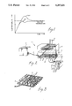
- FIG. 1 is a graph of temperature versus time for the nucleate boiling of immersion fluids. Curve 20 represents the temperature overshoot necessary to initiate nucleate boiling in the immersion fluids used in prior art nucleate boiling cooling systems.
- nucleate boiling cooling Another problem associated with nucleate boiling cooling is that as heat is dissipated from the device, more and more bubbles are formed, eventually creating a film.
- the onset of film boiling marks the upper limit of nucleate boiling because the film blocks the liquid from reaching the chip surface, thereby significantly restricting heat transfer from the devices and potentially causing destructive overheating, or thermal runaway, of the devices.
- the present invention relates generally to a method and apparatus for maintaining electrically operated devices at a predetermined desired temperature by immersing the device in an inert liquid which cools the device by nucleate boiling.
- the techniques employed by the present invention may be described in the environment frequently found in the semiconductor industry wherein the case temperature of a device is controlled during burn-in. Therefore, the present invention will be described in an environment wherein the temperature of the device is controlled by detecting and controlling the temperature of the case enclosing the device. In such burn-in testing, it is typical for industry burn-in specifications to require the device case to be maintained at a given temperature for an extended period of time; as a practical matter, the case forms a convenient point of attachment for a means to measure temperature.
- the invention provides a method for maintaining the case of an immersed electrically operating device at a desired temperature by controlling the rate of nucleate boiling of the immersion liquid during sustained burn-in testing of the device.
- a heat sink is attached to the device, and the device and heat sink are immersed in a bath of inert liquid having a boiling point lower than the desired case temperature.
- the device is supplied with electrical power, thereby generating heat which is transferred to the bath by nucleate boiling of the liquid.
- the device case temperature is monitored until it stabilizes at a temperature between the boiling point of the liquid and the desired case temperature.
- An inert liquid having a boiling point greater than the desired case temperature is slowly added to the bath to modify the rate of nucleate boiling of the lower-boiling liquid, while simultaneously monitoring the case temperature, until the case temperature stabilizes at the desired case temperature.
- a second embodiment of the present invention can be described in an environment wherein the temperature of the device is controlled by detecting and controlling the temperature of fluids in which the device is immersed, in other words, by detecting and controlling the ambient temperature of the device.
- the device is immersed in a bath of a high-temperature inert liquid having a boiling point greater than the desired ambient temperature; a heating element is also immersed in the bath. The heating element heats the high-temperature liquid to a temperature equal to the desired ambient temperature.
- the device is then supplied with electrical power while a low-temperature inert liquid having a boiling temperature below the desired ambient temperature is slowly added to the bath to initiate nucleate boiling of the low-temperature fluid so as to prevent the ambient temperature from exceeding the desired temperature.
- the ambient temperature is monitored until the bath stabilizes at the desired ambient temperature.
- the invention provides a method to maintain an electrically operating device within a predetermined range of minimum and maximum device temperatures during high temperature reverse bias burn-in.
- the device supplied with a means for monitoring device temperature, is immersed together with a heating element in a high-temperature inert liquid having a boiling point greater than the maximum device temperature.
- the bath is then heated with the heating element, and the device temperature is monitored, until it stabilizes at a temperature below the minimum device temperature.
- the device is gradually powered to the required reverse voltage until the device temperature stabilizes at a temperature higher than the minimum temperature.
- a low-temperature inert liquid having a boiling point less than the desired maximum device temperature is added to the bath to initiate nucleate boiling of the low-temperature fluid; the device temperature is monitored to ensure that it stays within the minimum and maximum temperatures.
- FIG. 1 is a graph useful in comparing the present invention with the prior art.
- FIG. 2 is a perspective view of a first embodiment of a burn-in unit including the present invention.
- FIG. 3 is a close-up view of the electrically operating devices tested in the burn-in unit of FIG. 2.
- FIG. 4 is a close-up view of the cooling coils used in the burn-in unit of FIG. 2.
- FIG. 5 is a perspective view of the burn-in unit of FIG. 2 in operation.
- FIG. 6 is a graph useful in illustrating temperature control in a second embodiment of the present invention, high temperature reverse bias (HTRB) burn-in.
- HTRB high temperature reverse bias
- FIG. 7 is a perspective view of a second embodiment of the present invention, exemplifying apparatus used for a high temperature reverse bias (HTRB) burn-in.
- HTRB high temperature reverse bias
- burn-in unit 1 includes a generally rectangular, substantially closed tank 2 containing transistors 3 to be subjected to a burn-in test; if the tank is sealed, it should be provided with a vent or other means to equalize internal tank pressure with the atmospheric pressure.
- Other devices suitable for burn-in testing according to the present invention include for example rectifiers, resistors and diodes.
- Transistors 3 are supplied with electrical power from power source 6 by means of electrical cord 7.
- thermocouples 5 are attached to a representative number of transistors 3 at a point on the transistor case 13 nearest the die, or source of heat generation. Thermocouple readings are recorded by temperature recorder 10.
- the case temperature can be monitored by measuring the infrared radiation given off by transistors 3 during the burn-in test.
- transistors 3 are attached to copper heat sink 4.
- Heat sink 4 provides an increased heat transfer area for transistors 3, to prevent destructive overheating or thermal runaway of the transistors and to keep the transistor case temperature uniform.
- heat sinks are not necessary if the particular devices under test transfer heat efficiently.
- a heat sink may actually make the device hotter by preventing cooling means from reaching the device.
- the transistor/heat sink assembly is immersed in a bath of an inert liquid such as a perfluorinated organic liquid 9, having a boiling point less than the desired burn-in case temperature.
- Power is supplied to transistors 3 and the temperature of transistor cases 13 is monitored.
- transistors 3 are cooled by transferring heat to the bath, initiating nucleate boiling of liquid 9, as indicated by reference numeral 11 in FIG. 5.
- a large portion of the heat transferred from transistors 3 is absorbed by liquid 9 as the latent heat of vaporization; the remainder is absorbed by convection of the liquid.
- the rising vapor bubbles of liquid 9 are condensed by cold water contained in two rows of 1/2 inch copper cooling coils 8 located in tank 2 above the bath (FIG. 4).
- the temperature of transistor cases 13 increases to a stabilization temperature between the boiling point of liquid 9 and the desired case temperature.
- an inert liquid preferably, a perfluorinated organic liquid miscible with the first liquid
- the second, higher-boiling liquid decreases the rate of heat transfer from transistors 3 by diluting the lower boiling fluid, thereby effectively quenching the high heat transfer rate caused by nucleate boiling of the first fluid. Therefore, the transistor case temperature will rise.
- addition of the second fluid is discontinued, and the case temperature will remain at the desired temperature.
- the burn-in test continues for the required period of time.
- the temperature of transistors 3 is closely monitored; if the temperature begins to increase above the desired case temperature, an additional amount of the first inert liquid is added to tank 2 to cool the transistor cases by nucleate boiling of the lower-boiling liquid. If too much of the first inert liquid is inadvertently added, this case temperature will drop below the desired case temperature; in that situation, additional higher boiling inert liquid is added to quench the nucleate boiling cooling from evaporation of the first inert liquid.
- the desired case temperature can be maintained within a margin of ⁇ 5° C.
- the two inert liquids can be separated by the usual distillation procedures and recycled for use in other burn-in tests.
- the temperature of the immersed device can be approximately monitored and/or controlled by placing thermocouples 5A immersion liquid or bath 9, as shown by dashed lines in FIG. 2, rather than on the device case, thus monitoring and controlling the ambient temperature of the immersed device; the thermocouple readings can be recorded as described above.
- the ambient temperature can be controlled within a narrow margin by selective addition of the high--and low--boiling inert fluids in the manner described above.
- the present invention avoids the hysteresis and device-overheating problems associated with the prior art because the temperature to initiate nucleate boiling of the lower-boiling immersion fluid is less than the desired case temperature; the higher-boiling fluid in fact does not approach its boiling point.
- FIGS. 6 and 7 illustrate another embodiment of the present invention, namely, high-temperature reverse bias (HTRB) burn-in.
- HTRB high-temperature reverse bias
- devices 30 are immersed in a high-temperature inert fluid 32, typically a perfluorinated organic liquid, having a boiling point greater than the specified maximum burn-in temperature, which is commonly either a specific device or device case temperature, or a specific ambient temperature such as a bath temperature.
- a high-temperature inert fluid 32 typically a perfluorinated organic liquid, having a boiling point greater than the specified maximum burn-in temperature, which is commonly either a specific device or device case temperature, or a specific ambient temperature such as a bath temperature.
- a means for monitoring temperature such as thermocouple 5.
- a heating element such as resistor or resistors 34, preferably located below devices 30, which resistors have a power supply 36.
- Resistors 34 heat fluid 32 until the temperature being monitored, either the device or the bath temperature, stabilizes at a temperature below the minimum specified temperature (as shown by reference numeral 38 in FIG. 6). At that point, devices 30 are gradually powered to the required reverse voltage, and temperature is monitored, preferably while a low-temperature inert fluid having a boiling point less than the specified minimum burn-in temperature is added to the bath to initiate nucleate boiling of the low-temperature fluid; alternatively, the low-temperature fluid can be added after the temperature being monitored reaches at least the desired minimum temperature.
- Addition of the low-temperature fluid continues until the temperature (indicated by reference numeral 40 in FIG. 6) reaches at least the desired minimum temperature; the low-temperature fluid serves to keep the monitored temperature (indicated by line 42 of FIG. 6) below the desired maximum burn-in temperature.
- the specified temperature whether of the device or ambient, can be controlled within a narrow margin by selected addition of the high-- and low-- boiling inert fluids in a manner analogous to that described above with respect to the first embodiment.
- the following example describes a two-week burn-in test of rectifier diodes supplied with 50 amps of electrical power.
- the required case temperature was 100° plus or minus 5° C.
- Twenty-two rectifier diodes were attached to copper heat sinks. Thermocouples were attached to three diodes at a point on the diode case nearest the source of heat.
- the diode/heat sink assembly was then placed in a burn-in tank.
- a perfluorinated organic liquid having a boiling point of 84° C. (D/80, manufactured by Ausimont Galden), was added to the tank until the diodes were completely immersed.
- the diodes were supplied with 50 amps of electrical power and the diode case temperature was monitored and recorded.
- the diode case temperature stabilized at a temperature of approximately 94° C. At that point, a perfluorinated organic liquid having a boiling point of 175° C. (DO 2 , manufactured by Ausimont Galden), was slowly added to the tank while the diode case temperature was monitored, until it reached the desired case temperature of 100° C. The diode case temperature was monitored for the burn-in period of two weeks; several times, the diode case temperature increased above the desired case temperature of 100° C. To decrease the case temperature to the desired to the desired level, D/80 was slowly added to the tank until the diode case temperature dropped to 100° C. During the burn-in test, vaporized D/80 was condensed by copper cooling coils containing 18° C. water and located above the bath. The condensed D/80 liquid streams dropped back into the bath.
- DO 2 perfluorinated organic liquid having a boiling point of 175° C.
- the following example describes a 160 hour ambient burn-in test of an immersed integrated circuit supplied with 0.5 watts of electrical power.
- the required ambient temperature of the surrounding fluid was 125° C.
- Two integrated circuit devices were inserted into test sockets on a burn-in board assembly, with a thermocouple placed near the devices to monitor the temperature of the immersion fluid or bath.
- the burn-in assembly connected to a first power supply, was then placed in a burn-in tank above heating elements powered by a second power supply.
- a perfluorinated organic liquid having a boiling point of 175° C. (DO2 manufactured by Ausimont Galden) was added to the tank until the devices were completely immersed.
- the integrated circuits were then supplied with 0.5 watts of electrical power and the ambient temperature was monitored and recorded.
- the perfluorinated liquids were then heated by the heating elements until the ambient temperature exceeded 125° C., at which time the lower boiling point perfluorinated organic liquid having a boiling point of 84° C. (D/80 manufactured by Ausimont Galden) was slowly added to the tank while the ambient or immersion fluid temperature was monitored until it reached the desired ambient temperature of 125° C.
- the ambient temperature was monitored for the burn-in period of 160 hours; several times, the ambient temperature increased above 125° C.
- D/80 was slowly added to the tank until the ambient temperature again dropped to 125° C.
- vaporized immersion fluid was condensed by copper cooling coils located above the bath which coils contained 18° C. water. The condensed immersion fluid streams dropped back into the bath from the coils.
- the following example describes a 1,000 hour high temperature reverse bias test of Schottky rectifier diodes supplied with 5.4 watts of electrical power.
- the required case temperature was 150° C. minimum.
- Nine Schottky rectifier diodes were attached to a wire rack biased with the reverse voltage.
- Thermocouples were attached to two diodes at a point on the diode case nearest the source of heat.
- the diode/wire rack assembly was then placed in a burn-in tank above a heating element powered by a separate power supply.
- a perfluorinated organic liquid having a boiling point of 175° C. (DO2 manufactured by Ausimont Galden) was added to the tank until the diodes were completely immersed.
- the perfluorinated liquid was first heated to 140° C.
- heating elements such as resistors 34 can also be used in processes such as the first embodiment described above, to increase the burn-in temperature above a standard burn-in temperature, thus accelerating the entire burn-in process and greatly decreasing device test time.
Abstract
Description
______________________________________
INVENTOR          U.S. PAT. NO.
______________________________________
N. K. G. Aakalu, et al.
                  3,741,292
R. C. Chu, et al. 4,050,507
Frieser, et al.   4,312,012
R. C. Chu, et al. 4,709,754
______________________________________
Claims (5)
Priority Applications (1)
| Application Number | Priority Date | Filing Date | Title |
|---|---|---|---|
| US07/835,711 US5297621A (en) | 1989-07-13 | 1992-02-12 | Method and apparatus for maintaining electrically operating device temperatures |
Applications Claiming Priority (3)
| Application Number | Priority Date | Filing Date | Title |
|---|---|---|---|
| US07/379,083 US5004973A (en) | 1989-07-13 | 1989-07-13 | Method and apparatus for maintaining electrically operating device temperatures |
| US07/633,382 US5099908A (en) | 1989-07-13 | 1990-12-20 | Method and apparatus for maintaining electrically operating device temperatures |
| US07/835,711 US5297621A (en) | 1989-07-13 | 1992-02-12 | Method and apparatus for maintaining electrically operating device temperatures |
Related Parent Applications (1)
| Application Number | Title | Priority Date | Filing Date |
|---|---|---|---|
| US07/633,382 Division US5099908A (en) | 1989-07-13 | 1990-12-20 | Method and apparatus for maintaining electrically operating device temperatures |
Publications (1)
| Publication Number | Publication Date |
|---|---|
| US5297621A true US5297621A (en) | 1994-03-29 |
Family
ID=46246556
Family Applications (1)
| Application Number | Title | Priority Date | Filing Date |
|---|---|---|---|
| US07/835,711 Expired - Fee Related US5297621A (en) | 1989-07-13 | 1992-02-12 | Method and apparatus for maintaining electrically operating device temperatures |
Country Status (1)
| Country | Link |
|---|---|
| US (1) | US5297621A (en) |
Cited By (51)
| Publication number | Priority date | Publication date | Assignee | Title |
|---|---|---|---|---|
| US5864176A (en) * | 1997-04-04 | 1999-01-26 | Unisys Corporation | Electro-mechnical subassembly having a greatly reduced thermal resistance between two mating faces by including a film of liquid, that evaporates without leaving any residue, between the faces |
| US6167948B1 (en) | 1996-11-18 | 2001-01-02 | Novel Concepts, Inc. | Thin, planar heat spreader |
| US6323665B1 (en) * | 1997-10-07 | 2001-11-27 | Reliability Incorporated | Apparatus capable of high power dissipation during burn-in of a device under test |
| US6389225B1 (en) | 1998-07-14 | 2002-05-14 | Delta Design, Inc. | Apparatus, method and system of liquid-based, wide range, fast response temperature control of electronic device |
| US6476627B1 (en) | 1996-10-21 | 2002-11-05 | Delta Design, Inc. | Method and apparatus for temperature control of a device during testing |
| US6489793B2 (en) | 1996-10-21 | 2002-12-03 | Delta Design, Inc. | Temperature control of electronic devices using power following feedback |
| US6518782B1 (en) | 2000-08-29 | 2003-02-11 | Delta Design, Inc. | Active power monitoring using externally located current sensors |
| US20070263356A1 (en) * | 2006-05-02 | 2007-11-15 | Raytheon Company | Method and Apparatus for Cooling Electronics with a Coolant at a Subambient Pressure |
| US20080196868A1 (en) * | 2006-05-16 | 2008-08-21 | Hardcore Computer, Inc. | Case for a liquid submersion cooled electronic device |
| US20080229780A1 (en) * | 2007-03-22 | 2008-09-25 | Raytheon Company | System and Method for Separating Components of a Fluid Coolant for Cooling a Structure |
| WO2010019517A1 (en) * | 2008-08-11 | 2010-02-18 | Green Revolution Cooling, Inc. | Liquid submerged, horizontal computer server rack and systems and methods of cooling such a server rack |
| US7934386B2 (en) | 2008-02-25 | 2011-05-03 | Raytheon Company | System and method for cooling a heat generating structure |
| US20110315343A1 (en) * | 2010-06-29 | 2011-12-29 | International Business Machines Corporation | Interleaved, immersion-cooling apparatuses and methods for cooling electronic subsystems |
| US20110315344A1 (en) * | 2010-06-29 | 2011-12-29 | International Business Machines Corporation | Interleaved, immersion-cooling apparatus and method for an electronic subsystem of an electronics rack |
| US20120012282A1 (en) * | 2007-05-15 | 2012-01-19 | Asetek A/S | Direct air contact liquid cooling system heat exchanger assembly |
| US8351206B2 (en) | 2010-06-29 | 2013-01-08 | International Business Machines Corporation | Liquid-cooled electronics rack with immersion-cooled electronic subsystems and vertically-mounted, vapor-condensing unit |
| US20140211412A1 (en) * | 2011-08-05 | 2014-07-31 | Green Revolution Cooling, Inc. | Hard drive cooling for fluid submersion cooling systems |
| US20140218858A1 (en) * | 2013-02-01 | 2014-08-07 | Dell Products L.P. | Stand Alone Immersion Tank Data Center with Contained Cooling |
| KR101437702B1 (en) * | 2006-05-16 | 2014-09-03 | 하드코어 컴퓨터, 인크. | Liquid submersion cooling system |
| US20150181762A1 (en) * | 2012-12-14 | 2015-06-25 | Midas Green Technology, Llc | Appliance Immersion Cooling System |
| US9258926B2 (en) * | 2014-06-24 | 2016-02-09 | David Lane Smith | System and method for fluid cooling of electronic devices installed in a sealed enclosure |
| US9366721B2 (en) * | 2014-09-25 | 2016-06-14 | Pentamaster Instrumentation Sdn Bhd | Apparatus for burn-in test |
| US9408332B2 (en) | 2014-06-24 | 2016-08-02 | David Lane Smith | System and method for fluid cooling of electronic devices installed in a sealed enclosure |
| US20160234970A1 (en) * | 2013-02-01 | 2016-08-11 | Dell Products, L.P. | Partitioned, Rotating Condenser Units to Enable Servicing of Submerged IT Equipment Positioned Beneath a Vapor Condenser Without Interrupting a Vaporization-Condensation Cycling of the Remaining Immersion Cooling System |
| US9504190B2 (en) | 2013-05-06 | 2016-11-22 | Green Revolution Cooling, Inc. | System and method of packaging computing resources for space and fire-resistance |
| WO2017015052A1 (en) | 2015-07-21 | 2017-01-26 | Delta Design, Inc. | Continuous fluidic thermal interface material dispensing |
| US9560789B2 (en) | 2014-06-24 | 2017-01-31 | David Lane Smith | System and method for fluid cooling of electronic devices installed in a sealed enclosure |
| US20170156233A1 (en) * | 2015-12-01 | 2017-06-01 | Dell Products, L.P. | Dry power supply assembly for immersion-cooled information handling systems |
| US9699939B2 (en) | 2014-06-24 | 2017-07-04 | David Lane Smith | System and method for fluid cooling of electronic devices installed in a sealed enclosure |
| US9756766B2 (en) | 2014-05-13 | 2017-09-05 | Green Revolution Cooling, Inc. | System and method for air-cooling hard drives in liquid-cooled server rack |
| US10257960B1 (en) | 2018-07-23 | 2019-04-09 | TAS Energy, Inc. | Power distribution for immersion-cooled information systems |
| US10321603B1 (en) | 2018-07-23 | 2019-06-11 | TAS Energy, Inc. | Electrical power distribution for immersion cooled information systems |
| US10667437B2 (en) * | 2018-04-12 | 2020-05-26 | Baidu Usa Llc | Liquid distribution unit design for liquid cooling of electronic racks of a data center |
| EP3683588A1 (en) * | 2019-01-17 | 2020-07-22 | Lisa Dräxlmaier GmbH | Method and test device for testing an electronic component |
| US10757839B2 (en) * | 2015-10-28 | 2020-08-25 | Dawning Information Industry (Beijing) Co., Ltd. | Cooling system and device for server |
| US10782751B1 (en) * | 2019-05-07 | 2020-09-22 | Stephane Gauthier | Cooling a computer processing unit |
| WO2020223806A1 (en) * | 2019-05-07 | 2020-11-12 | Stephane Gauthier | Cooling a computer processing unit |
| US10925188B1 (en) * | 2019-11-11 | 2021-02-16 | Microsoft Technology Licensing, Llc | Self-contained immersion cooling server assemblies |
| US11069383B1 (en) | 2020-04-06 | 2021-07-20 | Seagate Technology Llc | Thermal interface materials for immersion cooled data storage devices |
| US11074943B2 (en) | 2019-11-11 | 2021-07-27 | Seagate Technology Llc | Methods and devices for alleviating thermal boil off in immersion-cooled electronic devices |
| US11191186B2 (en) | 2014-06-24 | 2021-11-30 | David Lane Smith | System and method for fluid cooling of electronic devices installed in an enclosure |
| US11359865B2 (en) | 2018-07-23 | 2022-06-14 | Green Revolution Cooling, Inc. | Dual Cooling Tower Time Share Water Treatment System |
| US11375638B2 (en) * | 2020-01-15 | 2022-06-28 | Wiwynn Corporation | Immersion cooling apparatus |
| US20220408587A1 (en) * | 2021-06-21 | 2022-12-22 | Microsoft Technology Licensing, Llc | Systems and methods for immersion-cooled computers |
| US20220408601A1 (en) * | 2021-06-22 | 2022-12-22 | Baidu Usa Llc | Electronics packaging for phase change cooling systems |
| US20220418147A1 (en) * | 2021-06-23 | 2022-12-29 | Baidu Usa Llc | Multi-phase change thermal management systems for servers |
| USD982145S1 (en) | 2020-10-19 | 2023-03-28 | Green Revolution Cooling, Inc. | Cooling system enclosure |
| US11744041B2 (en) | 2014-06-24 | 2023-08-29 | David Lane Smith | System and method for fluid cooling of electronic devices installed in an enclosure |
| USD998770S1 (en) | 2020-10-19 | 2023-09-12 | Green Revolution Cooling, Inc. | Cooling system enclosure |
| US11805624B2 (en) | 2021-09-17 | 2023-10-31 | Green Revolution Cooling, Inc. | Coolant shroud |
| US11925946B2 (en) | 2022-03-28 | 2024-03-12 | Green Revolution Cooling, Inc. | Fluid delivery wand |
Citations (6)
| Publication number | Priority date | Publication date | Assignee | Title |
|---|---|---|---|---|
| GB818281A (en) * | 1954-10-09 | 1959-08-12 | Tno | A method of transferring heat to a boiling liquid in the nucleate boiling stage |
| US3406244A (en) * | 1966-06-07 | 1968-10-15 | Ibm | Multi-liquid heat transfer |
| US4050507A (en) * | 1975-06-27 | 1977-09-27 | International Business Machines Corporation | Method for customizing nucleate boiling heat transfer from electronic units immersed in dielectric coolant |
| US4741385A (en) * | 1986-02-18 | 1988-05-03 | Iowa State University Research Foundation, Inc. | Gas jet impingement means and method |
| US4745354A (en) * | 1985-05-20 | 1988-05-17 | Fts Systems, Inc. | Apparatus and methods for effecting a burn-in procedure on semiconductor devices |
| US4779424A (en) * | 1987-01-13 | 1988-10-25 | Hisaka Works, Limited | Heat recovery system utilizing non-azeotropic medium |
-
1992
- 1992-02-12 US US07/835,711 patent/US5297621A/en not_active Expired - Fee Related
Patent Citations (6)
| Publication number | Priority date | Publication date | Assignee | Title |
|---|---|---|---|---|
| GB818281A (en) * | 1954-10-09 | 1959-08-12 | Tno | A method of transferring heat to a boiling liquid in the nucleate boiling stage |
| US3406244A (en) * | 1966-06-07 | 1968-10-15 | Ibm | Multi-liquid heat transfer |
| US4050507A (en) * | 1975-06-27 | 1977-09-27 | International Business Machines Corporation | Method for customizing nucleate boiling heat transfer from electronic units immersed in dielectric coolant |
| US4745354A (en) * | 1985-05-20 | 1988-05-17 | Fts Systems, Inc. | Apparatus and methods for effecting a burn-in procedure on semiconductor devices |
| US4741385A (en) * | 1986-02-18 | 1988-05-03 | Iowa State University Research Foundation, Inc. | Gas jet impingement means and method |
| US4779424A (en) * | 1987-01-13 | 1988-10-25 | Hisaka Works, Limited | Heat recovery system utilizing non-azeotropic medium |
Non-Patent Citations (4)
| Title |
|---|
| Shock, R. A. W. Nucleate Boiling in Binary Mixtures, Int. Journal Heat Mass Transfer, vol. 20, pp. 701 709, Pergamon Press, 1977. * |
| Shock, R. A. W. Nucleate Boiling in Binary Mixtures, Int. Journal Heat Mass Transfer, vol. 20, pp. 701-709, Pergamon Press, 1977. |
| Yokouchi et al, K. Immersion Cooling for High Density Packaging IEEE Transactions on Components, Hybrids and Manufacturing Technology vol. CHMT 12, No. 4, Dec. 1987, pp. 643 646. * |
| Yokouchi et al, K. Immersion Cooling for High Density Packaging IEEE Transactions on Components, Hybrids and Manufacturing Technology vol. CHMT-12, No. 4, Dec. 1987, pp. 643-646. |
Cited By (77)
| Publication number | Priority date | Publication date | Assignee | Title |
|---|---|---|---|---|
| US6650132B2 (en) | 1996-10-21 | 2003-11-18 | Delta Design, Inc. | Method and apparatus for temperature control of a device during testing |
| US6476627B1 (en) | 1996-10-21 | 2002-11-05 | Delta Design, Inc. | Method and apparatus for temperature control of a device during testing |
| US6489793B2 (en) | 1996-10-21 | 2002-12-03 | Delta Design, Inc. | Temperature control of electronic devices using power following feedback |
| US6788084B2 (en) | 1996-10-21 | 2004-09-07 | Delta Design, Inc. | Temperature control of electronic devices using power following feedback |
| US6167948B1 (en) | 1996-11-18 | 2001-01-02 | Novel Concepts, Inc. | Thin, planar heat spreader |
| US5864176A (en) * | 1997-04-04 | 1999-01-26 | Unisys Corporation | Electro-mechnical subassembly having a greatly reduced thermal resistance between two mating faces by including a film of liquid, that evaporates without leaving any residue, between the faces |
| US6323665B1 (en) * | 1997-10-07 | 2001-11-27 | Reliability Incorporated | Apparatus capable of high power dissipation during burn-in of a device under test |
| US6389225B1 (en) | 1998-07-14 | 2002-05-14 | Delta Design, Inc. | Apparatus, method and system of liquid-based, wide range, fast response temperature control of electronic device |
| US6549026B1 (en) | 1998-07-14 | 2003-04-15 | Delta Design, Inc. | Apparatus and method for temperature control of IC device during test |
| US6862405B2 (en) | 1998-07-14 | 2005-03-01 | Delta Design, Inc. | Apparatus, method and system of liquid-based, wide range, fast response temperature control of electric devices |
| US6518782B1 (en) | 2000-08-29 | 2003-02-11 | Delta Design, Inc. | Active power monitoring using externally located current sensors |
| US20070263356A1 (en) * | 2006-05-02 | 2007-11-15 | Raytheon Company | Method and Apparatus for Cooling Electronics with a Coolant at a Subambient Pressure |
| US7908874B2 (en) * | 2006-05-02 | 2011-03-22 | Raytheon Company | Method and apparatus for cooling electronics with a coolant at a subambient pressure |
| US20080196868A1 (en) * | 2006-05-16 | 2008-08-21 | Hardcore Computer, Inc. | Case for a liquid submersion cooled electronic device |
| US7724517B2 (en) * | 2006-05-16 | 2010-05-25 | Hardcore Computer, Inc. | Case for a liquid submersion cooled electronic device |
| KR101437702B1 (en) * | 2006-05-16 | 2014-09-03 | 하드코어 컴퓨터, 인크. | Liquid submersion cooling system |
| US20080229780A1 (en) * | 2007-03-22 | 2008-09-25 | Raytheon Company | System and Method for Separating Components of a Fluid Coolant for Cooling a Structure |
| US8651172B2 (en) | 2007-03-22 | 2014-02-18 | Raytheon Company | System and method for separating components of a fluid coolant for cooling a structure |
| US20120012282A1 (en) * | 2007-05-15 | 2012-01-19 | Asetek A/S | Direct air contact liquid cooling system heat exchanger assembly |
| US7934386B2 (en) | 2008-02-25 | 2011-05-03 | Raytheon Company | System and method for cooling a heat generating structure |
| US10123463B2 (en) | 2008-08-11 | 2018-11-06 | Green Revolution Cooling, Inc. | Liquid submerged, horizontal computer server rack and systems and method of cooling such a server rack |
| US9992914B2 (en) | 2008-08-11 | 2018-06-05 | Green Revolution Cooling, Inc. | Commmonly submersed servers with velocity augmentation and partial recirculation in tank |
| WO2010019517A1 (en) * | 2008-08-11 | 2010-02-18 | Green Revolution Cooling, Inc. | Liquid submerged, horizontal computer server rack and systems and methods of cooling such a server rack |
| EP2321849A4 (en) * | 2008-08-11 | 2017-07-05 | Green Revolution Cooling, Inc. | Liquid submerged, horizontal computer server rack and systems and methods of cooling such a server rack |
| CN102160171A (en) * | 2008-08-11 | 2011-08-17 | 绿色革命冷却股份有限公司 | Liquid submerged, horizontal computer server rack and systems and methods of cooling such a server rack |
| CN102160171B (en) * | 2008-08-11 | 2015-07-22 | 绿色革命冷却股份有限公司 | Liquid submerged, horizontal computer server rack and systems and methods of cooling such a server rack |
| US20110132579A1 (en) * | 2008-08-11 | 2011-06-09 | Green Revolution Cooling, Inc. | Liquid Submerged, Horizontal Computer Server Rack and Systems and Method of Cooling such a Server Rack |
| US8351206B2 (en) | 2010-06-29 | 2013-01-08 | International Business Machines Corporation | Liquid-cooled electronics rack with immersion-cooled electronic subsystems and vertically-mounted, vapor-condensing unit |
| US20110315343A1 (en) * | 2010-06-29 | 2011-12-29 | International Business Machines Corporation | Interleaved, immersion-cooling apparatuses and methods for cooling electronic subsystems |
| US8345423B2 (en) * | 2010-06-29 | 2013-01-01 | International Business Machines Corporation | Interleaved, immersion-cooling apparatuses and methods for cooling electronic subsystems |
| US8369091B2 (en) * | 2010-06-29 | 2013-02-05 | International Business Machines Corporation | Interleaved, immersion-cooling apparatus and method for an electronic subsystem of an electronics rack |
| US20110315344A1 (en) * | 2010-06-29 | 2011-12-29 | International Business Machines Corporation | Interleaved, immersion-cooling apparatus and method for an electronic subsystem of an electronics rack |
| US20140211412A1 (en) * | 2011-08-05 | 2014-07-31 | Green Revolution Cooling, Inc. | Hard drive cooling for fluid submersion cooling systems |
| US20190200482A1 (en) * | 2012-12-14 | 2019-06-27 | Midas Green Technology, Llc | Appliance Immersion Cooling System |
| US10820446B2 (en) * | 2012-12-14 | 2020-10-27 | Midas Green Technologies, Llc | Appliance immersion cooling system |
| US10405457B2 (en) * | 2012-12-14 | 2019-09-03 | Midas Green Technologies, Llc | Appliance immersion cooling system |
| US20150181762A1 (en) * | 2012-12-14 | 2015-06-25 | Midas Green Technology, Llc | Appliance Immersion Cooling System |
| US20160234970A1 (en) * | 2013-02-01 | 2016-08-11 | Dell Products, L.P. | Partitioned, Rotating Condenser Units to Enable Servicing of Submerged IT Equipment Positioned Beneath a Vapor Condenser Without Interrupting a Vaporization-Condensation Cycling of the Remaining Immersion Cooling System |
| US10143113B2 (en) * | 2013-02-01 | 2018-11-27 | Dell Products, L.P. | Partitioned, rotating condenser units to enable servicing of submerged IT equipment positioned beneath a vapor condenser without interrupting a vaporization-condensation cycling of the remaining immersion cooling system |
| US9921622B2 (en) * | 2013-02-01 | 2018-03-20 | Dell Products, L.P. | Stand alone immersion tank data center with contained cooling |
| US20140218858A1 (en) * | 2013-02-01 | 2014-08-07 | Dell Products L.P. | Stand Alone Immersion Tank Data Center with Contained Cooling |
| US9504190B2 (en) | 2013-05-06 | 2016-11-22 | Green Revolution Cooling, Inc. | System and method of packaging computing resources for space and fire-resistance |
| US10624242B2 (en) | 2013-05-06 | 2020-04-14 | Green Revolution Cooling, Inc. | System and method of packaging computing resources for space and fire-resistance |
| US9756766B2 (en) | 2014-05-13 | 2017-09-05 | Green Revolution Cooling, Inc. | System and method for air-cooling hard drives in liquid-cooled server rack |
| US11191186B2 (en) | 2014-06-24 | 2021-11-30 | David Lane Smith | System and method for fluid cooling of electronic devices installed in an enclosure |
| US9699939B2 (en) | 2014-06-24 | 2017-07-04 | David Lane Smith | System and method for fluid cooling of electronic devices installed in a sealed enclosure |
| US11744041B2 (en) | 2014-06-24 | 2023-08-29 | David Lane Smith | System and method for fluid cooling of electronic devices installed in an enclosure |
| US9560789B2 (en) | 2014-06-24 | 2017-01-31 | David Lane Smith | System and method for fluid cooling of electronic devices installed in a sealed enclosure |
| US9408332B2 (en) | 2014-06-24 | 2016-08-02 | David Lane Smith | System and method for fluid cooling of electronic devices installed in a sealed enclosure |
| US9258926B2 (en) * | 2014-06-24 | 2016-02-09 | David Lane Smith | System and method for fluid cooling of electronic devices installed in a sealed enclosure |
| US9366721B2 (en) * | 2014-09-25 | 2016-06-14 | Pentamaster Instrumentation Sdn Bhd | Apparatus for burn-in test |
| WO2017015052A1 (en) | 2015-07-21 | 2017-01-26 | Delta Design, Inc. | Continuous fluidic thermal interface material dispensing |
| US10757839B2 (en) * | 2015-10-28 | 2020-08-25 | Dawning Information Industry (Beijing) Co., Ltd. | Cooling system and device for server |
| US9872415B2 (en) * | 2015-12-01 | 2018-01-16 | Dell Products, L.P. | Dry power supply assembly for immersion-cooled information handling systems |
| US20170156233A1 (en) * | 2015-12-01 | 2017-06-01 | Dell Products, L.P. | Dry power supply assembly for immersion-cooled information handling systems |
| US10667437B2 (en) * | 2018-04-12 | 2020-05-26 | Baidu Usa Llc | Liquid distribution unit design for liquid cooling of electronic racks of a data center |
| US11272642B2 (en) * | 2018-04-12 | 2022-03-08 | Baidu Usa Llc | Liquid distribution unit design for liquid cooling of electronic racks of a data center |
| US10257960B1 (en) | 2018-07-23 | 2019-04-09 | TAS Energy, Inc. | Power distribution for immersion-cooled information systems |
| US10321603B1 (en) | 2018-07-23 | 2019-06-11 | TAS Energy, Inc. | Electrical power distribution for immersion cooled information systems |
| US11359865B2 (en) | 2018-07-23 | 2022-06-14 | Green Revolution Cooling, Inc. | Dual Cooling Tower Time Share Water Treatment System |
| EP3683588A1 (en) * | 2019-01-17 | 2020-07-22 | Lisa Dräxlmaier GmbH | Method and test device for testing an electronic component |
| WO2020223806A1 (en) * | 2019-05-07 | 2020-11-12 | Stephane Gauthier | Cooling a computer processing unit |
| US10782751B1 (en) * | 2019-05-07 | 2020-09-22 | Stephane Gauthier | Cooling a computer processing unit |
| US11074943B2 (en) | 2019-11-11 | 2021-07-27 | Seagate Technology Llc | Methods and devices for alleviating thermal boil off in immersion-cooled electronic devices |
| US10925188B1 (en) * | 2019-11-11 | 2021-02-16 | Microsoft Technology Licensing, Llc | Self-contained immersion cooling server assemblies |
| US11483949B2 (en) * | 2019-11-11 | 2022-10-25 | Microsoft Technology Licensing, Llc | Self-contained immersion cooling server assemblies |
| US11375638B2 (en) * | 2020-01-15 | 2022-06-28 | Wiwynn Corporation | Immersion cooling apparatus |
| US11069383B1 (en) | 2020-04-06 | 2021-07-20 | Seagate Technology Llc | Thermal interface materials for immersion cooled data storage devices |
| USD982145S1 (en) | 2020-10-19 | 2023-03-28 | Green Revolution Cooling, Inc. | Cooling system enclosure |
| USD998770S1 (en) | 2020-10-19 | 2023-09-12 | Green Revolution Cooling, Inc. | Cooling system enclosure |
| US20220408587A1 (en) * | 2021-06-21 | 2022-12-22 | Microsoft Technology Licensing, Llc | Systems and methods for immersion-cooled computers |
| US20220408601A1 (en) * | 2021-06-22 | 2022-12-22 | Baidu Usa Llc | Electronics packaging for phase change cooling systems |
| US11744043B2 (en) * | 2021-06-22 | 2023-08-29 | Baidu Usa Llc | Electronics packaging for phase change cooling systems |
| US20220418147A1 (en) * | 2021-06-23 | 2022-12-29 | Baidu Usa Llc | Multi-phase change thermal management systems for servers |
| US11606879B2 (en) * | 2021-06-23 | 2023-03-14 | Baidu Usa Llc | Multi-phase change thermal management systems for servers |
| US11805624B2 (en) | 2021-09-17 | 2023-10-31 | Green Revolution Cooling, Inc. | Coolant shroud |
| US11925946B2 (en) | 2022-03-28 | 2024-03-12 | Green Revolution Cooling, Inc. | Fluid delivery wand |
Similar Documents
| Publication | Publication Date | Title |
|---|---|---|
| US5297621A (en) | Method and apparatus for maintaining electrically operating device temperatures | |
| US5099908A (en) | Method and apparatus for maintaining electrically operating device temperatures | |
| US4203129A (en) | Bubble generating tunnels for cooling semiconductor devices | |
| US5740016A (en) | Solid state temperature controlled substrate holder | |
| US5119021A (en) | Method and apparatus for maintaining electrically operating device temperatures | |
| US5004973A (en) | Method and apparatus for maintaining electrically operating device temperatures | |
| JP4122009B2 (en) | Electromechanical subassembly and method for thermally coupling an electronic device to a heat exchange member | |
| KR100765929B1 (en) | Temperature control method and temperature control device | |
| Meysenc et al. | Power electronics cooling effectiveness versus thermal inertia | |
| US20050117296A1 (en) | Ball grid array package with heat sink device | |
| JPH0587873A (en) | Method and device for selecting burn-in of integrated circuit chip | |
| US6663278B1 (en) | Method for determining the thermal performance of a heat sink | |
| US11061067B2 (en) | Apparatus and method for a high temperature test and a low temperature test and configured to maintain an electronic component under test near a test temperature | |
| Manno et al. | Microcontact-enhanced thermoelectric cooling of ultrahigh heat flux hotspots | |
| Honda et al. | Enhanced boiling heat transfer from silicon chips with micro-pin fins immersed in FC-72 | |
| Honda et al. | Effect of the size of micro-pin-fin on boiling heat transfer from silicon chips immersed in FC-72 | |
| US11871667B2 (en) | Methods and apparatus for warpage correction | |
| Alley et al. | Modeling and validation of on-die cooling of dual-core CPU using embedded thermoelectric devices | |
| Panigrahy et al. | Small Form Factor Peltier-Based Liquid Cooling for High Power Density Electronics | |
| Tian et al. | Experimental study on the immersion cooling of an upward‐facing multichip module with an opposing condensing surface | |
| US20040248430A1 (en) | Wafer cooling chuck with direct coupled peltier unit | |
| JPH11337614A (en) | Measuring mechanism for high-temperature handler | |
| Kotlar et al. | Cooling method for high power dissipation SMD packages | |
| Liu et al. | A novel method for measuring the temperature in the active region of semiconductor modules | |
| JPS63226936A (en) | Mounting stage for semiconductor wafer |
Legal Events
| Date | Code | Title | Description |
|---|---|---|---|
| AS | Assignment |
Owner name: MICROSEMI CORPORATION, CALIFORNIA Free format text: ASSIGNMENT OF ASSIGNORS INTEREST.;ASSIGNOR:THERMAL MANAGEMENT CORPORATION;REEL/FRAME:006452/0525 Effective date: 19930130 Owner name: JOHN E. FETZER INSTITUTE, INC., THE, MICHIGAN Free format text: ASSIGNMENT OF ASSIGNORS INTEREST.;ASSIGNOR:THERMAL MANAGEMENT CORPORATION;REEL/FRAME:006452/0516 Effective date: 19930130 |
|
| FEPP | Fee payment procedure |
Free format text: PAYOR NUMBER ASSIGNED (ORIGINAL EVENT CODE: ASPN); ENTITY STATUS OF PATENT OWNER: SMALL ENTITY |
|
| FPAY | Fee payment |
Year of fee payment: 4 |
|
| FPAY | Fee payment |
Year of fee payment: 8 |
|
| REMI | Maintenance fee reminder mailed | ||
| LAPS | Lapse for failure to pay maintenance fees | ||
| STCH | Information on status: patent discontinuation |
Free format text: PATENT EXPIRED DUE TO NONPAYMENT OF MAINTENANCE FEES UNDER 37 CFR 1.362 |
|
| FP | Lapsed due to failure to pay maintenance fee |
Effective date: 20060329 |
|
| AS | Assignment |
Owner name: MORGAN STANLEY & CO. INCORPORATED, NEW YORK Free format text: PATENT SECURITY AGREEMENT;ASSIGNORS:WHITE ELECTRONIC DESIGNS CORP.;ACTEL CORPORATION;MICROSEMI CORPORATION;REEL/FRAME:025783/0613 Effective date: 20110111 |
|
| AS | Assignment |
Owner name: MICROSEMI CORPORATION, CALIFORNIA Free format text: RELEASE BY SECURED PARTY;ASSIGNOR:BANK OF AMERICA, N.A.;REEL/FRAME:037558/0711 Effective date: 20160115 Owner name: MICROSEMI FREQUENCY AND TIME CORPORATION, A DELAWA Free format text: RELEASE BY SECURED PARTY;ASSIGNOR:BANK OF AMERICA, N.A.;REEL/FRAME:037558/0711 Effective date: 20160115 Owner name: MICROSEMI SEMICONDUCTOR (U.S.) INC., A DELAWARE CO Free format text: RELEASE BY SECURED PARTY;ASSIGNOR:BANK OF AMERICA, N.A.;REEL/FRAME:037558/0711 Effective date: 20160115 Owner name: MICROSEMI CORP.-ANALOG MIXED SIGNAL GROUP, A DELAW Free format text: RELEASE BY SECURED PARTY;ASSIGNOR:BANK OF AMERICA, N.A.;REEL/FRAME:037558/0711 Effective date: 20160115 Owner name: MICROSEMI SOC CORP., A CALIFORNIA CORPORATION, CAL Free format text: RELEASE BY SECURED PARTY;ASSIGNOR:BANK OF AMERICA, N.A.;REEL/FRAME:037558/0711 Effective date: 20160115 Owner name: MICROSEMI COMMUNICATIONS, INC. (F/K/A VITESSE SEMI Free format text: RELEASE BY SECURED PARTY;ASSIGNOR:BANK OF AMERICA, N.A.;REEL/FRAME:037558/0711 Effective date: 20160115 Owner name: MICROSEMI CORP.-MEMORY AND STORAGE SOLUTIONS (F/K/ Free format text: RELEASE BY SECURED PARTY;ASSIGNOR:BANK OF AMERICA, N.A.;REEL/FRAME:037558/0711 Effective date: 20160115 |