US5280728A - Ultrasonic flow velocity measurement method and apparatus thereof - Google Patents
Ultrasonic flow velocity measurement method and apparatus thereof Download PDFInfo
- Publication number
- US5280728A US5280728A US07/782,095 US78209591A US5280728A US 5280728 A US5280728 A US 5280728A US 78209591 A US78209591 A US 78209591A US 5280728 A US5280728 A US 5280728A
- Authority
- US
- United States
- Prior art keywords
- pipe
- ultrasonic
- ultrasonic wave
- wedge
- flow velocity
- Prior art date
- Legal status (The legal status is an assumption and is not a legal conclusion. Google has not performed a legal analysis and makes no representation as to the accuracy of the status listed.)
- Expired - Fee Related
Links
Images


Classifications
-
- G—PHYSICS
- G01—MEASURING; TESTING
- G01F—MEASURING VOLUME, VOLUME FLOW, MASS FLOW OR LIQUID LEVEL; METERING BY VOLUME
- G01F1/00—Measuring the volume flow or mass flow of fluid or fluent solid material wherein the fluid passes through a meter in a continuous flow
- G01F1/66—Measuring the volume flow or mass flow of fluid or fluent solid material wherein the fluid passes through a meter in a continuous flow by measuring frequency, phase shift or propagation time of electromagnetic or other waves, e.g. using ultrasonic flowmeters
- G01F1/662—Constructional details
-
- G—PHYSICS
- G01—MEASURING; TESTING
- G01F—MEASURING VOLUME, VOLUME FLOW, MASS FLOW OR LIQUID LEVEL; METERING BY VOLUME
- G01F1/00—Measuring the volume flow or mass flow of fluid or fluent solid material wherein the fluid passes through a meter in a continuous flow
- G01F1/66—Measuring the volume flow or mass flow of fluid or fluent solid material wherein the fluid passes through a meter in a continuous flow by measuring frequency, phase shift or propagation time of electromagnetic or other waves, e.g. using ultrasonic flowmeters
- G01F1/667—Arrangements of transducers for ultrasonic flowmeters; Circuits for operating ultrasonic flowmeters
Definitions
- the present invention relates to an ultrasonic flow velocity measurement method and apparatus thereof. More particularly, the present invention relates to an ultrasonic flow velocity measurement method in which ultrasonic wave transducers are installed on the outer surface of a pipe and the flow velocity of a fluid at a high temperature and pressure or at a low temperature inside the pipe is measured, and to an apparatus thereof.
- FIGS. 9 and 10 An example of the prior art shown in FIGS. 9 and 10 is disclosed in U.S. Pat. No. 4,930,358.
- reference numeral 51 denotes one of the ultrasonic wave transducers mounted on the upstream side of a pipe 3
- reference numeral 52 denotes the other ultrasonic wave transducer mounted on the downstream side of the pipe 3.
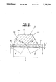
- the ultrasonic wave transducer 51 comprises a wedge member 51A for making ultrasonic waves enter the pipe 3 obliquely and a vibrator 51B, as shown in FIG. 10.
- the wedge member 51A is formed of an acrylic resin and the cross section thereof is shaped as a trapezoid.
- the ultrasonic vibrator 51B is fixedly mounted on one of the inclined surfaces 51a thereof.
- the other inclined surface 51C forms an ultrasonic reflection surface intersecting at right angles with a propagation path when ultrasonic waves originated from the vibrator 51B are reflected by a surface 51b serving as an ultrasonic incident surface and the ultrasonic waves are propagated within the wedge member 51A. Hence, internal reflection waves propagated inside the wedge member 51A return to the vibrator 51B.
- a sound velocity C 1 within a wedge inside the ultrasonic wave transducers 51 and 52 can be determined by the following equation:
- l 1 and l' 1 are the length of the paths l 1 and l' 1 shown in FIG. 10, respectively, and ⁇ e is an electrical delay time inside a cable or the like.
- the length b of the incident surface 51b which serves as an opening surface when ultrasonic waves inside a pipe are emanated, is set at almost 18 wavelengths or even greater with respect to the central frequency used.
- an ultrasonic beam which is propagated in turn in the wedge section inside the ultrasonic wave transducer, in the pipe section and in the fluid section inside the pipe, is regarded as a substantially parallel beam.
- Ultrasonic waves outputted from the vibrator 51B of the ultrasonic wave transducer 51 toward the downstream side pass through a propagation path consisting of parallel beams shown by a slanted line in FIG. 9 and reach the ultrasonic vibrator 52B of the other ultrasonic wave transducer 52.
- the propagation time in this case is denoted as t d .
- the propagation time in this case is denoted as t u .
- C 2 is a predetermined sound velocity inside the pipe wall.
- the sound velocity C 1 determined from t p by using equation 1 indicates an average sound velocity within the wedge.
- the sound velocity C 1 has a problem (drawback) in that a large error occurs when the flow velocity of a fluid at a high temperature and pressure is measured, since the sound velocity C 1 is obviously different from a sound velocity in which Snell's law is applied because a propagation path for ultrasonic waves is indentified.
- the present invention has been accomplished to solve the above-mentioned problems of the prior art.
- An object of the present invention is to provide an ultrasonic flow velocity measuring method which is capable of measuring the flow velocity of a fluid inside a pipe at a high temperature and pressure efficiently and with a high degree of accuracy, and an apparatus thereof.
- the ultrasonic flow velocity measurement method of the present invention comprises the steps of: placing two ultrasonic wave transducers, the directional angles of which are formed considerably small, at a proper distance from each other on the upstream and downstream sides of a pipe to be measured; measuring an average propagation sound velocity C 1 in a wedge section inside each of the ultrasonic wave transducer during this taking of this measurement and a sound velocity C' 1 on the surface where the wedge contacts the pipe to be measured by making ultrasonic waves alternately enter the pipe from outer walls of the upstream and downstream sides thereof, respectively; oscillating ultrasonic waves from the upstream side to the downstream side of the pipe and vice versa, almost simultaneously with when these measurements are made, and measuring in turn times t.sub. ⁇ and t u from when the ultrasonic waves are oscillated to when they are received after they propagate a wall of the pipe and a fluid inside the pipe; and substituting these measured values C 1 , C' 1 , t.sub. ⁇ and
- the ultrasonic flow velocity measuring apparatus comprises ultrasonic wave transducers on the upstream and downstream sides of a pipe along an ultrasonic propagation line, the directional angles of which are considerably small, in which a switching section of the ultrasonic wave transducers for switching alternately a transmission circuit section and a reception circuit section as required is disposed; timing means for measuring propagation times t d and t u from when ultrasonic waves are outputted from the ultrasonic wave transducers and transmitted from the upstream side to the downstream side of the pipe and vice versa to when these ultrasonic waves are received after they propagate a wall of the pipe and a fluid inside the pipe, and storing means for storing the propagation times t d and t u and a mounting distance Lx between the ultrasonic wave transducers, the above two means being disposed in the reception circuit section; and flow velocity computing means for storing a measured value of an average propagation sound velocity C 1 in a wedge section inside each of the ultrasonic wave transducers during the taking of this measurement
- FIG. 1 is a view which illustrates the entire construction of an embodiment of the present invention
- FIG. 2 is a view which illustrates a wedge section in FIG. 1;
- FIG. 3 is a block diagram which illustrates a signal processing system of the apparatus in the embodiment
- FIG. 4 is a chart which illustrates the measured data of FIG. 3;
- FIG. 5 is a view which illustrates an example of an experiment apparatus
- FIG. 6 is a chart which illustrates the relationship between the propagation time of ultrasonic waves and temperatures within a wedge member
- FIGS. 7 and 8 are each views which illustrate other embodiments.
- FIGS. 9 and 10 are each views which illustrate a conventional apparatus.
- reference numeral 1 denotes one of the ultrasonic wave transducers disposed on the upstream side of a pipe 3; and reference numeral 2 denotes the other ultrasonic wave transducers disposed on the downstream side of the pipe 3.
- the one ultrasonic wave transducer 1 comprises a wedge member IA for making ultrasonic waves obliquely enter the pipe 3 and a vibrator IB, as shown in FIG. 2.
- the wedge member IA is formed of a metal member so that it can withstand high temperatures and the temperature thereof falls below a maximum operating temperature limit of a vibrator at a place of an ultrasonic vibrator 1B by reflecting heat.
- the entire wedge member IA is formed into an relatively long guide bar which serves as an ultrasonic propagation path.
- the vibrator 1B is fixedly mounted on one of the inclined surfaces 1a.
- the other inclined surface 1c forms an ultrasonic reflection surface intersecting at right angles with a propagation path when ultrasonic waves originating from the vibrator IB are reflected by an incident surface lb serving as an ultrasonic incident surface and the ultrasonic waves propagate within the wedge member IA.
- incident surface lb serving as an ultrasonic incident surface and the ultrasonic waves propagate within the wedge member IA.
- An ultrasonic wave transducer is disposed in a pipe through which a fluid in a high temparature and pressure state flows.
- a metal plate 3A which simulates an actual pipe to be measured is mounted on a hot plate 30 the temperature of which can be varied, as shown in FIG. 5.
- the relationship between t p and a temperature T R on a surface where the wedge contacts the pipe to be measured is determined as shown in FIG. 6. From this FIG. 6, the relationship between t p and T R is determined by the following equation:
- the length b of the incident surface 1b which serves as an opening surface when ultrasonic waves inside a pipe are emanated, is set at almost 18 wavelengths or greater with respect to the central frequency used.
- an ultrasonic beam which propagates in turn in the wedge section inside an ultrasonic wave transducer, in the pipe section and in the fluid section inside the pipe, is regarded as a substantially parallel beam.
- the ultrasonic wave transducers 1 and 2 are connected, via a transmission/reception switching section 10, to a transmission circuit section 11 and a reception circuit section 12, respectively, as shown in FIG. 3. Repeat signals shown in FIG. 4 are received by each of the ultrasonic wave transducers 1 and 2 according to the flow velocity inside the pipe 3. As shown in FIG. 3, ultrasonic waves outputted from the ultrasonic wave transducer 1 on the upstream side are divided into propagation waves A which propagate inside the wall of the pipe 3 and propagation waves B which propagate, through the wall of the pipe 3, into the liquid inside the pipe 3.
- a signal indicating the reception of incoming ultrasonic waves shown in FIG. 4(1) is sent, via a reception circuit section 12 and a signal selecting means 13A in a control apparatus 20, to a timing means 13 where a propagation time t d is timed.
- the time t d is temporarily stored in a memory 14.
- a signal indicating the reception of incoming ultrasonic waves shown in FIG. 4(2) is sent to a timing means 13 where a propagation time t u is timed and temporarily stored in a memory 14.
- an average propagation sound velocity C 1 , within the wedge inside the ultrasonic wave transducer, and a sound velocity C' 1 on the surface where the wedge contacts the pipe to be measured, are measured. This need not be performed each time a flow velocity is measured. It is only necessary that the measurement be performed when required.
- either one of the ultrasonic wave transducers 1 and 2 is connected, via the transmission/reception switching section 10 shown in FIG. 3, to the transmission circuit section 11 and the reception circuit section 12.
- the ultrasonic wave transducer 1 is connected, via the transmission/reception switching section 10 shown in FIG. 3, to the transmission circuit section 11 and the reception circuit section 12.
- the ultrasonic wave transducer 1 is connected, ultrasonic waves oscillated from the vibrator IB shown in FIG. 2 are received by the vibrator 1B in FIG. 3 of passages l' 1 and l 1 .
- This signal is sent, via the reception circuit section 12 and a signal selecting means 13A, to the timing means 13 where the propagation time thereof, t p
- Each of the propagation times t d , t u and t p stored in the memory 14 is immediately sent to a computing means 17.
- a flow velocity V computed and determined by this computing means 17 on the basis of equation 2 is displayed on a display means 18. Furthermore, the quantity of flow is computed by the computing means 17 from the flow velocity V and the area of the cross section inside the pipe and is also displayed on the display means 18.
- Reference numeral 13 in FIG. 3 denotes a main control section that controls a series of operations of these component means.
- a sound velocity C' 1 on the surface where the wedge of the ultrasonic wave transducers 1 and 2 contacts a pipe to be measured is determined by the following equation after T R is determined from the measured t p by using equation 4:
- T.sub.(ref) is the temperature at that time
- l 1 and l' 1 are the length of the passages l 1 and l' 1 shown in FIG. 7, respectively
- ⁇ e is an electrical delay time inside a cable or the like.
- the average sound velocity C 1 within the wedge is determined from C' 1 by the following equation:
- Lx is the distance between 1R and 2R, intersection points between vibrator contact surfaces 1a and 2a and ultrasonic wave emanating surfaces 1b and 2b respectively;
- ⁇ 1 is an incident angle of the ultrasonic waves within the wedge;
- C 2 is the sound velocity of a fluid inside the pipe wall;
- C 3 is the sound velocity of a fluid at a high temperature;
- d is the plate thickness of the pipe;
- Equation 9 indicates that the sound velocity C 3 of a fluid at a high temperature and pressure can be determined accurately at any time.
- flow velocity V can be computed by Snell's law as shown below:
- predetermined functions described in claim 1 refer to all of a group of functions including equations 4, 5, 7, 10and 11 with equation 12 as the center.
- FIG. 7 shows another embodiment.
- T R need not be determined from t p by using the relationship of FIG. 6 by a method in which a temperature sensor 40 is mounted at a place near a pipe to be measured of the wedge section of an ultrasonic wave transducer and a temperature T R on the surface where the wedge contacts the pipe to be measured is directly monitored.
- An example of mounting the temperature sensor 40 is shown in FIG. 7.
- FIG. 8 shows a further embodiment.
- the position of the ultrasonic wave transducer 2 on the downstream side is changed. Measurement of flow velocity is possible on principles similar to that described above by changing the number N of propagation passages or the like.
- the present invention can be applied not only to flow velocity measurement of fluids at high temperatures and pressure but also to flow velocity measurement of very low-temperature fluids, such as liquid nitrogen, liquid oxygen or liquefied natural gas, by using an ultrasonic wave transducer, having a wedge section in the form of a guide bar, in which a wedge member is used which can withstand low temperatures for the purpose of protecting vibrators which are ultrasonic wave generating sources.
- very low-temperature fluids such as liquid nitrogen, liquid oxygen or liquefied natural gas
- the present invention Since the present invention is constructed and functions as described above, it can provide an ultrasonic flow velocity measuring method and apparatus thereof for fluids at high temperatures and pressure by accurately measuring an average sound velocity in the wedge section of an ultrasonic wave transducer having a temperature gradient, namely, a sound velocity gradient, and a sound velocity on the surface where the wedge contacts the pipe to be measured.
- the present invention has noted advantages such that the flow velocity measurement can be performed with a high degree of accuracy without requiring temperature compensation.
Abstract
An ultrasonic flow velocity measurement method and apparatus thereof and comprises ultrasonic wave transducers disposed on the upstream and downstream sides of a pipe and a control apparatus connected to these ultrasonic wave transducers. Concerning the flow velocity measurement, an average propagation sound velocity in the wedge which forms the ultrasonic wave transducers and the sound velocity on the surface where the wedge is brought into contact with the pipe are measured. The time from when ultrasonic waves are originated from the upstream side to the downstream side and and vice versa and to when they are received is measured. These measured values and the distance between the ultrasonic wave transducers are substituted for a predetermined function to determine the flow velocity of a fluid inside the pipe.
Description
1. Field of the Invention
The present invention relates to an ultrasonic flow velocity measurement method and apparatus thereof. More particularly, the present invention relates to an ultrasonic flow velocity measurement method in which ultrasonic wave transducers are installed on the outer surface of a pipe and the flow velocity of a fluid at a high temperature and pressure or at a low temperature inside the pipe is measured, and to an apparatus thereof.
2. Description of the Related Art
An example of the prior art shown in FIGS. 9 and 10 is disclosed in U.S. Pat. No. 4,930,358.
In these figures, reference numeral 51 denotes one of the ultrasonic wave transducers mounted on the upstream side of a pipe 3, and reference numeral 52 denotes the other ultrasonic wave transducer mounted on the downstream side of the pipe 3. The ultrasonic wave transducer 51 comprises a wedge member 51A for making ultrasonic waves enter the pipe 3 obliquely and a vibrator 51B, as shown in FIG. 10. The wedge member 51A is formed of an acrylic resin and the cross section thereof is shaped as a trapezoid. The ultrasonic vibrator 51B is fixedly mounted on one of the inclined surfaces 51a thereof. The other inclined surface 51C forms an ultrasonic reflection surface intersecting at right angles with a propagation path when ultrasonic waves originated from the vibrator 51B are reflected by a surface 51b serving as an ultrasonic incident surface and the ultrasonic waves are propagated within the wedge member 51A. Hence, internal reflection waves propagated inside the wedge member 51A return to the vibrator 51B.
If this propagation time is denoted as tp, a sound velocity C1 within a wedge inside the ultrasonic wave transducers 51 and 52 can be determined by the following equation:
C.sub.1 =2(l.sub.1 +l'.sub.1)/(t.sub.p -τ.sub.e) 1
where l1 and l'1 are the length of the paths l1 and l'1 shown in FIG. 10, respectively, and τe is an electrical delay time inside a cable or the like. The length b of the incident surface 51b which serves as an opening surface when ultrasonic waves inside a pipe are emanated, is set at almost 18 wavelengths or even greater with respect to the central frequency used.
Since a directional angle becomes very small when the opening of the vibrator 51B is somewhat long and the length b of the incident surface 51b is almost 18 wavelengths or even greater as shown in FIG. 9, an ultrasonic beam, which is propagated in turn in the wedge section inside the ultrasonic wave transducer, in the pipe section and in the fluid section inside the pipe, is regarded as a substantially parallel beam.
Ultrasonic waves outputted from the vibrator 51B of the ultrasonic wave transducer 51 toward the downstream side pass through a propagation path consisting of parallel beams shown by a slanted line in FIG. 9 and reach the ultrasonic vibrator 52B of the other ultrasonic wave transducer 52. The propagation time in this case is denoted as td.
Ultrasonic waves outputted from the vibrator 52B of the ultrasonic wave transducer 52 toward the upstream side reach an ultrasonic vibrator 51B of the other ultrasonic wave transducer 51. The propagation time in this case is denoted as tu.
In such a case, a flow velocity V inside the pipe 3 can be determined by the following equation: ##EQU1## where Lx is the distance between the intersecting points of the inclined surfaces 51a and 52a where vibrators contact the incident surfaces 51b and 52b, i.e., between 1R and 2R; θ1 is an incident angle of the ultrasonic waves within the wedge; d is the plate thickness of the pipe; D is the internal diameter of the pipe; and N is the number of passages of the ultrasonic waves inside the fluid. In the case of FIG. 9, N=2. C2 is a predetermined sound velocity inside the pipe wall.
As a result, even if the sound velocity C3 of a fluid is unknown, the flow velocity of the fluid inside the pipe 3 can be measured relatively easily on the basis of equations 2 and 3. At the same time, since the internal diameter of the pipe 3 is known, the quantity of flow of the fluid inside the pipe 3 can be determined quite easily.
Furthermore, incident points inside an ultrasonic wave transducer need not be strictly specified. Since it is necessary to know only the mounting distance Lx, setting the ultrasonic wave transducer is quite easy.
In addition, since ultrasonic waves emanated from the two ultrasonic wave transducers 51 and 52 have quite small directional angles, the transducers are immune to influences of the resonance mode (plate waves) of the pipe 3 which often becomes a problem in measuring.
However, such a conventional ultrasonic flow velocity measuring method and apparatus thereof cannot be used to measure the flow velocity of a fluid in a high temperature and pressure state (or in a low temperature state), if the construction thereof is not changed, since the vibrators 51B and 52B of the ultrasonic wave transducers 51 and 52 have a maximum operating temperature limit.
In addition, since a velocity gradient is caused in the sound velocity C1 within the wedge because of the temperature gradient caused within this wedge, the sound velocity C1 determined from tp by using equation 1 indicates an average sound velocity within the wedge. The sound velocity C1 has a problem (drawback) in that a large error occurs when the flow velocity of a fluid at a high temperature and pressure is measured, since the sound velocity C1 is obviously different from a sound velocity in which Snell's law is applied because a propagation path for ultrasonic waves is indentified.
The present invention has been accomplished to solve the above-mentioned problems of the prior art.
An object of the present invention is to provide an ultrasonic flow velocity measuring method which is capable of measuring the flow velocity of a fluid inside a pipe at a high temperature and pressure efficiently and with a high degree of accuracy, and an apparatus thereof.
In order to achieve the above-mentioned objects, the ultrasonic flow velocity measurement method of the present invention comprises the steps of: placing two ultrasonic wave transducers, the directional angles of which are formed considerably small, at a proper distance from each other on the upstream and downstream sides of a pipe to be measured; measuring an average propagation sound velocity C1 in a wedge section inside each of the ultrasonic wave transducer during this taking of this measurement and a sound velocity C'1 on the surface where the wedge contacts the pipe to be measured by making ultrasonic waves alternately enter the pipe from outer walls of the upstream and downstream sides thereof, respectively; oscillating ultrasonic waves from the upstream side to the downstream side of the pipe and vice versa, almost simultaneously with when these measurements are made, and measuring in turn times t.sub.α and tu from when the ultrasonic waves are oscillated to when they are received after they propagate a wall of the pipe and a fluid inside the pipe; and substituting these measured values C1, C'1, t.sub.α and tu, and a distance Lx between the ultrasonic wave transducers for a predetermined function which has been previously specified, as V=F (C1, C'1, t.sub.α, tu, Lx), and computing this function along with other constants in order to compute the flow velocity V of the fluid inside the pipe.
The ultrasonic flow velocity measuring apparatus comprises ultrasonic wave transducers on the upstream and downstream sides of a pipe along an ultrasonic propagation line, the directional angles of which are considerably small, in which a switching section of the ultrasonic wave transducers for switching alternately a transmission circuit section and a reception circuit section as required is disposed; timing means for measuring propagation times td and tu from when ultrasonic waves are outputted from the ultrasonic wave transducers and transmitted from the upstream side to the downstream side of the pipe and vice versa to when these ultrasonic waves are received after they propagate a wall of the pipe and a fluid inside the pipe, and storing means for storing the propagation times td and tu and a mounting distance Lx between the ultrasonic wave transducers, the above two means being disposed in the reception circuit section; and flow velocity computing means for storing a measured value of an average propagation sound velocity C1 in a wedge section inside each of the ultrasonic wave transducers during the taking of this measurement, a sound velocity C'1 on the surface where the wedge contacts the pipe to be measured and other necessary constants and for performing predetermined computations on the basis of the information outputted from this storing means in order to determine the flow velocity of the fluid inside the pipe.
The aforementioned and other objects, features and advantages of the present invention will become clear when reference is made to the following description of the preferred embodiments of the present invention, together with reference to the accompanying drawings.
FIG. 1 is a view which illustrates the entire construction of an embodiment of the present invention;
FIG. 2 is a view which illustrates a wedge section in FIG. 1;
FIG. 3 is a block diagram which illustrates a signal processing system of the apparatus in the embodiment;
FIG. 4 is a chart which illustrates the measured data of FIG. 3;
FIG. 5 is a view which illustrates an example of an experiment apparatus;
FIG. 6 is a chart which illustrates the relationship between the propagation time of ultrasonic waves and temperatures within a wedge member;
FIGS. 7 and 8 are each views which illustrate other embodiments; and
FIGS. 9 and 10 are each views which illustrate a conventional apparatus.
An embodiment of the present invention will be explained below with reference to FIGS. 1 through 6.
In FIG. 1, reference numeral 1 denotes one of the ultrasonic wave transducers disposed on the upstream side of a pipe 3; and reference numeral 2 denotes the other ultrasonic wave transducers disposed on the downstream side of the pipe 3. The one ultrasonic wave transducer 1 comprises a wedge member IA for making ultrasonic waves obliquely enter the pipe 3 and a vibrator IB, as shown in FIG. 2. The wedge member IA is formed of a metal member so that it can withstand high temperatures and the temperature thereof falls below a maximum operating temperature limit of a vibrator at a place of an ultrasonic vibrator 1B by reflecting heat. The entire wedge member IA is formed into an relatively long guide bar which serves as an ultrasonic propagation path. The vibrator 1B is fixedly mounted on one of the inclined surfaces 1a. The other inclined surface 1c forms an ultrasonic reflection surface intersecting at right angles with a propagation path when ultrasonic waves originating from the vibrator IB are reflected by an incident surface lb serving as an ultrasonic incident surface and the ultrasonic waves propagate within the wedge member IA. Hence, internal reflection waves which propagate inside the wedge member 1A return to the vibrator 1B.
An ultrasonic wave transducer is disposed in a pipe through which a fluid in a high temparature and pressure state flows. Before a flow velocity is measured, a metal plate 3A which simulates an actual pipe to be measured is mounted on a hot plate 30 the temperature of which can be varied, as shown in FIG. 5. By changing the temperature of the hot plate in a state close to the actual state used in which the metal plate 3A is covered with a material 3B to be actually used for keeping it warm, the relationship between tp and a temperature TR on a surface where the wedge contacts the pipe to be measured is determined as shown in FIG. 6. From this FIG. 6, the relationship between tp and TR is determined by the following equation:
T.sub.R =m·t.sub.p +n 4
where m and n are real numbers.
The length b of the incident surface 1b, which serves as an opening surface when ultrasonic waves inside a pipe are emanated, is set at almost 18 wavelengths or greater with respect to the central frequency used.
Since a directional angle becomes very small when the opening of the vibrator 1B is somewhat long and the length b of the incident surface 1b is almost 18 wavelengths or greater as shown in FIG. 1, an ultrasonic beam, which propagates in turn in the wedge section inside an ultrasonic wave transducer, in the pipe section and in the fluid section inside the pipe, is regarded as a substantially parallel beam.
The ultrasonic wave transducers 1 and 2 are connected, via a transmission/reception switching section 10, to a transmission circuit section 11 and a reception circuit section 12, respectively, as shown in FIG. 3. Repeat signals shown in FIG. 4 are received by each of the ultrasonic wave transducers 1 and 2 according to the flow velocity inside the pipe 3. As shown in FIG. 3, ultrasonic waves outputted from the ultrasonic wave transducer 1 on the upstream side are divided into propagation waves A which propagate inside the wall of the pipe 3 and propagation waves B which propagate, through the wall of the pipe 3, into the liquid inside the pipe 3.
This will be described in more detail. First, when ultrasonic waves are output from the upstream side toward the downstream side, a signal indicating the reception of incoming ultrasonic waves shown in FIG. 4(1) is sent, via a reception circuit section 12 and a signal selecting means 13A in a control apparatus 20, to a timing means 13 where a propagation time td is timed. The time td is temporarily stored in a memory 14.
Next, when the transmission/reception switching section 10 is activated and ultrasonic waves are output from the downstream side toward the upstream side, a signal indicating the reception of incoming ultrasonic waves shown in FIG. 4(2) is sent to a timing means 13 where a propagation time tu is timed and temporarily stored in a memory 14.
Next, almost simultaneously with the above-described operation, an average propagation sound velocity C1, within the wedge inside the ultrasonic wave transducer, and a sound velocity C'1 on the surface where the wedge contacts the pipe to be measured, are measured. This need not be performed each time a flow velocity is measured. It is only necessary that the measurement be performed when required. When the sound velocity within the wedge is measured, either one of the ultrasonic wave transducers 1 and 2 is connected, via the transmission/reception switching section 10 shown in FIG. 3, to the transmission circuit section 11 and the reception circuit section 12. For example, when the ultrasonic wave transducer 1 is connected, ultrasonic waves oscillated from the vibrator IB shown in FIG. 2 are received by the vibrator 1B in FIG. 3 of passages l'1 and l1. This signal is sent, via the reception circuit section 12 and a signal selecting means 13A, to the timing means 13 where the propagation time thereof, tp, is timed and temporarily stored in the memory 14.
Each of the propagation times td, tu and tp stored in the memory 14 is immediately sent to a computing means 17. A flow velocity V computed and determined by this computing means 17 on the basis of equation 2 is displayed on a display means 18. Furthermore, the quantity of flow is computed by the computing means 17 from the flow velocity V and the area of the cross section inside the pipe and is also displayed on the display means 18. Reference numeral 13 in FIG. 3 denotes a main control section that controls a series of operations of these component means.
A sound velocity C'1 on the surface where the wedge of the ultrasonic wave transducers 1 and 2 contacts a pipe to be measured is determined by the following equation after TR is determined from the measured tp by using equation 4:
C'.sub.1 =C.sub.1(ref) -d(T.sub.R -T.sub.(ref)) 5
where d is a temperature coefficient of the sound velocity of a wedge material; C1(ref) is determined by the following equation:
C.sub.1(ref) =2(l.sub.1 +l'.sub.1)/(t.sub.p -τ.sub.e) 6
T.sub.(ref) is the temperature at that time, l1 and l'1 are the length of the passages l1 and l'1 shown in FIG. 7, respectively, and τe is an electrical delay time inside a cable or the like.
The average sound velocity C1 within the wedge is determined from C'1 by the following equation:
C.sub.1 =2L'.sub.1 /[(t.sub.p -τ.sub.e)-2(l.sub.1 /C'.sub.1)]7
The total propagation time t: when the flow velocity V=0 is the following:
t.sub.0 = (Lx/C.sub.1)sinθ.sub.1 +(2d/C.sub.1 C.sub.2 · VIII.sub.1 +(ND/C.sub.1 C.sub.3) · VIII.sub.2 +τ.sub.e 8
In the above equation,
VIII.sub.1 = (C.sub.1 C'.sub.1 - C.sub.2.sup.2 sin.sup.2 θ.sub.1 ) / (26 C'.sub.1.sup.2 - C.sub.2.sup.2 sin.sup.2 θ.sub.1).sup.1/2 ;
VIII.sub.2 = (C.sub.1 C'.sub.1 - C.sub.3.sup.2 sinθ.sub.1) / (C'.sub.1.sup.2 - C.sub.3.sup.2 sin.sup.2 θ.sub.1).sup.1/2 ;
Lx is the distance between 1R and 2R, intersection points between vibrator contact surfaces 1a and 2a and ultrasonic wave emanating surfaces 1b and 2b respectively; θ1 is an incident angle of the ultrasonic waves within the wedge; C2 is the sound velocity of a fluid inside the pipe wall; C3 is the sound velocity of a fluid at a high temperature; d is the plate thickness of the pipe; D is the internal diameter of the pipe; and N is the number of passages of ultrasonic waves within the fluid, N=2 in the case of FIG. 2.
Rearranging equation 8 with respect to C3, we have:
C.sub.3 =ND(2C'.sub.1 C.sub.1 -C'.sub.1.sup.2).sup.1/2 /IX 9
where
IX=[C.sub.1.sup.2 (t.sub.0 -τ).sup.2 ⃡(NDsinθ.sub.1).sup.2 ].sup.1/2
τ = (Lx / C.sub.1) sinθ.sub.1 + [(2d / C.sub.1 C.sub.2) (C.sub.1 C'.sub.1 - C.sub.2.sup.2 sin.sup.2 θ.sub.1)/(C'.sub.1.sup.2 - C.sub.2.sup.2 sin.sup.2 θ.sub.1).sup.1/2 + ]τ.sub.e 10
Equation 9 indicates that the sound velocity C3 of a fluid at a high temperature and pressure can be determined accurately at any time.
Furthermore, the flow velocity V can be computed by Snell's law as shown below:
sinθ.sub.1 /C'.sub.1 =sinθ.sub.3 /C.sub.3 11,
C3 and the approximation of V (for instance, when a fluid at a high temperature and pressure is water, C3 =1,000 to 1,500 [m/s], and even the maximum value of V is 20 [m/s]):
V=(C.sub.3.sup.2 /2NDtanθ.sub.3) (t.sub.u -t.sub.d) 12
As a result, if constants (for example, the length l1 of the passage within the wedge, l'1 mounting distance Lx, etc.) necessary for calculating equations 4 through 11 are stored in the memory 14 beforehand, the flow velocity V of a fluid at a high temperatures and pressure state can be computed by using equations 4 through 11.
From the above viewpoint, predetermined functions described in claim 1 refer to all of a group of functions including equations 4, 5, 7, 10and 11 with equation 12 as the center.
FIG. 7 shows another embodiment.
In this embodiment, TR need not be determined from tp by using the relationship of FIG. 6 by a method in which a temperature sensor 40 is mounted at a place near a pipe to be measured of the wedge section of an ultrasonic wave transducer and a temperature TR on the surface where the wedge contacts the pipe to be measured is directly monitored. An example of mounting the temperature sensor 40 is shown in FIG. 7.
FIG. 8 shows a further embodiment. In this embodiment, the position of the ultrasonic wave transducer 2 on the downstream side is changed. Measurement of flow velocity is possible on principles similar to that described above by changing the number N of propagation passages or the like.
The present invention can be applied not only to flow velocity measurement of fluids at high temperatures and pressure but also to flow velocity measurement of very low-temperature fluids, such as liquid nitrogen, liquid oxygen or liquefied natural gas, by using an ultrasonic wave transducer, having a wedge section in the form of a guide bar, in which a wedge member is used which can withstand low temperatures for the purpose of protecting vibrators which are ultrasonic wave generating sources.
Since the present invention is constructed and functions as described above, it can provide an ultrasonic flow velocity measuring method and apparatus thereof for fluids at high temperatures and pressure by accurately measuring an average sound velocity in the wedge section of an ultrasonic wave transducer having a temperature gradient, namely, a sound velocity gradient, and a sound velocity on the surface where the wedge contacts the pipe to be measured. The present invention has noted advantages such that the flow velocity measurement can be performed with a high degree of accuracy without requiring temperature compensation.
Many different embodiments of the present invention may be constructed without departing from the spirit and scope of the present invention. It should be understood that the present invention is not limited to the specific embodiments described in this specification, and is only limited in the appended claims.
Claims (5)
1. An ultrasonic flow velocity determination method, comprising the steps of:
placing two ultrasonic wave transducers, including wedge sections, the directional angles of which are formed considerably small, at a proper distance from each other on the upstream and downstream sides of a pipe to be measured;
determining an average propagation sound velocity C1 in a wedge section inside each of the ultrasonic wave transducers during said determination of the flow velocity and determining a sound velocity C'1 on the surface where the wedge section contacts the pipe to be measured by making ultrasonic waves alternately enter the pipe from outer walls of the upstream and downstream sides thereof, respectively;
oscillating ultrasonic waves from the upstream side to the downstream side of the pipe and vice versa, at approximately the same time that said sound velocities are determined, and measuring in turn times td and tu from when the ultrasonic waves are oscillated to when they are received after they propagate a wall of the pipe and a fluid inside the pipe; and
substituting the determined values C1 and C'1, and the measured values td and tu, and a distance Lx between the ultrasonic wave transducers into the predetermined function V=F (C1, C'1, td, tu, Lx), and computing this function along with other constants in order to compute the flow velocity V of the fluid inside the pipe.
2. An ultrasonic flow velocity determination apparatus, comprising:
ultrasonic wave transducers on the upstream and downstream side of a pipe, including wedge sections, along an ultrasonic propagation line, the directional angles of which are considerably small, in which a switching section of the ultrasonic wave transducers for switching alternately a transmission circuit section and a reception circuit section is disposed;
timing means for measuring propagation times dd, tu and tp, from when ultrasonic waves are outputted from the ultrasonic wave transducers and transmitted from the upstream side to the downstream side of the pipe and vice versa to when these ultrasonic waves are received after they propagate a wall of the pipe and a fluid inside the pipe, and from when internal reflection waves propagated inside said wedges sections are reflected within said wedge sections and return to said transducers, respectively, and means for storing said propagation times td, tu, tp and a mounting distance Lx between said ultrasonic wave transducers, said timing means and said means for storing propagation times being disposed in said reception circuit section;
means for measuring a reference temperature T.sub.(ref) where each said wedge section contacts a surface of the pipe to be measured, for use in determination of a sound velocity C'1 ;
means for determining an average propagation sound velocity C1 in each said wedge sections inside each of said ultrasonic wave transducers during the determination of the flow velocity, and the sound velocity C'1 on the surface where each said wedge contacts the pipe to be measured;
means for storing said determined value of the average propagation sound velocity C1 in each said wedge section inside each of said ultrasonic wave transducers, said sound velocity C'1 on the surface where each said wedge contacts the pipe to be measured, and other necessary constants; and
means for performing predetermined computations on the basis of the information outputted from said propagation times storing means and said means for storing velocities in order to determine the flow velocity of the fluid inside the pipe.
3. An ultrasonic flow velocity determination apparatus according to claim 2, wherein each of said wedge sections comprises an ultrasonic-wave propagation passage having first and second ends along the length thereof, and wherein an ultrasonic reflection surface is disposed on said first end and each of said ultrasonic wave transducers is disposed on said second end to enable determination of said average propagation velocity C1 and said sound velocity C'1.
4. An ultrasonic flow velocity determination apparatus according to claim 2, wherein said ultrasonic wave transducers each further comprise a vibrator for emitting ultrasonic vibrations, and each said wedge is formed of a metal member, to withstand temperatures which are higher than those being capable of handled by wedges made of acrylic resins, and to reflect heat from said vibrator in each of said ultrasonic wave transducers.
5. An ultrasonic flow velocity determination apparatus according to claim 4, each said ultrasonic wave transducer further comprising a vibrator mounted section having an elongated guide bar shape.
Applications Claiming Priority (2)
| Application Number | Priority Date | Filing Date | Title |
|---|---|---|---|
| JP2-299234 | 1990-11-05 | ||
| JP2299234A JP2747618B2 (en) | 1990-11-05 | 1990-11-05 | Ultrasonic flow velocity measuring method and apparatus |
Publications (1)
| Publication Number | Publication Date |
|---|---|
| US5280728A true US5280728A (en) | 1994-01-25 |
Family
ID=17869884
Family Applications (1)
| Application Number | Title | Priority Date | Filing Date |
|---|---|---|---|
| US07/782,095 Expired - Fee Related US5280728A (en) | 1990-11-05 | 1991-10-24 | Ultrasonic flow velocity measurement method and apparatus thereof |
Country Status (2)
| Country | Link |
|---|---|
| US (1) | US5280728A (en) |
| JP (1) | JP2747618B2 (en) |
Cited By (49)
| Publication number | Priority date | Publication date | Assignee | Title |
|---|---|---|---|---|
| WO1997008516A1 (en) * | 1995-08-22 | 1997-03-06 | Krohne Ag | Volumetric flow meter |
| US5856622A (en) * | 1995-03-20 | 1999-01-05 | Fuji Electric Co., Ltd. | Clamp-on type ultrasonic flow meter and a temperature and pressure compensation method therein |
| US6065350A (en) * | 1998-07-10 | 2000-05-23 | Panametrics, Inc. | Flow measurement system with guided signal launched in lowest mode |
| US20020016557A1 (en) * | 1997-02-14 | 2002-02-07 | Duarte Luiz R. | Ultrasonic treatment for wounds |
| US20030125902A1 (en) * | 2002-01-03 | 2003-07-03 | Freund William R. | Peak switch detector for transit time ultrasonic meters |
| US20030153849A1 (en) * | 1997-02-06 | 2003-08-14 | Huckle James William | Method and apparatus for connective tissue treatment |
| DE10312034B3 (en) * | 2003-03-06 | 2004-03-18 | Krohne Ag | Ultrasonic throughflow measurement involves ultrasonic signal transition time measurement between ultrasonic transducers for multiple immediately successive transitions of defined path in medium |
| US20050096548A1 (en) * | 2000-10-25 | 2005-05-05 | Talish Roger J. | Transducer mounting assembly |
| US20060016243A1 (en) * | 2004-07-21 | 2006-01-26 | Nevius Timothy A | Acoustic flowmeter calibration method |
| US20060106424A1 (en) * | 2004-09-04 | 2006-05-18 | Max Bachem | Ultrasound device and method of use |
| US20070208280A1 (en) * | 1998-05-06 | 2007-09-06 | Talish Roger J | Ultrasound bandage |
| US7429248B1 (en) * | 2001-08-09 | 2008-09-30 | Exogen, Inc. | Method and apparatus for controlling acoustic modes in tissue healing applications |
| DE102007020491A1 (en) * | 2007-04-27 | 2008-10-30 | Hydrometer Gmbh | Method for determining a property of a flowing medium and ultrasonic meters |
| DE102007062913A1 (en) * | 2007-12-21 | 2009-06-25 | Endress + Hauser Flowtec Ag | Ultrasonic transducer i.e. clamp-on ultrasonic transducer, for use in process and automation technology, has coupling element, where exit of ultrasonic signal from coupling element in signal path is registered by piezo-electric element |
| DE10057188B4 (en) * | 2000-11-17 | 2010-07-01 | Endress + Hauser Flowtec Ag | Ultrasonic flowmeter with temperature compensation |
| WO2011078691A2 (en) | 2009-12-22 | 2011-06-30 | Tecom As C/O Christian Michelsen Research As | Measuring apparatus |
| US20110239730A1 (en) * | 2010-04-06 | 2011-10-06 | Krohne Ag | Calibration device for mass flow meters |
| US20110271769A1 (en) * | 2009-12-21 | 2011-11-10 | Tecom As | Flow measuring apparatus |
| CN101587098B (en) * | 2008-05-21 | 2012-05-16 | 山东省科学院激光研究所 | Steel tube ultrasonic inspection method capable of simultaneously realizing three functions in one channel |
| DE102010063535A1 (en) * | 2010-12-20 | 2012-06-21 | Endress + Hauser Flowtec Ag | Coupling element of an ultrasonic transducer for an ultrasonic flowmeter |
| US20120186350A1 (en) * | 2009-10-01 | 2012-07-26 | Panasonic Corporation | Ultrasonic flow meter unit |
| EP2687828A1 (en) * | 2012-07-18 | 2014-01-22 | General Electric Company | Ultrasonic wedge and method for determining the speed of sound in same |
| WO2014021846A1 (en) * | 2012-07-31 | 2014-02-06 | Siemens Aktiengesellschaft | Indirect transducer temperature measurement |
| US8857269B2 (en) | 2010-08-05 | 2014-10-14 | Hospira, Inc. | Method of varying the flow rate of fluid from a medical pump and hybrid sensor system performing the same |
| US20160061778A1 (en) * | 2013-10-23 | 2016-03-03 | Fuji Electric Co., Ltd. | Fluid measuring device |
| US10022498B2 (en) | 2011-12-16 | 2018-07-17 | Icu Medical, Inc. | System for monitoring and delivering medication to a patient and method of using the same to minimize the risks associated with automated therapy |
| US10166328B2 (en) | 2013-05-29 | 2019-01-01 | Icu Medical, Inc. | Infusion system which utilizes one or more sensors and additional information to make an air determination regarding the infusion system |
| CN109459103A (en) * | 2018-12-25 | 2019-03-12 | 上海诺自动化工程有限公司 | A kind of ultrasonic type gas-liquid two-phase measuring device |
| US10342917B2 (en) | 2014-02-28 | 2019-07-09 | Icu Medical, Inc. | Infusion system and method which utilizes dual wavelength optical air-in-line detection |
| US10430761B2 (en) | 2011-08-19 | 2019-10-01 | Icu Medical, Inc. | Systems and methods for a graphical interface including a graphical representation of medical data |
| GB2572802A (en) * | 2018-04-11 | 2019-10-16 | Disonics Ltd | Flowmeter |
| US10463788B2 (en) | 2012-07-31 | 2019-11-05 | Icu Medical, Inc. | Patient care system for critical medications |
| US20200049544A1 (en) * | 2018-08-11 | 2020-02-13 | Diehl Metering Gmbh | Method for operating a measuring device and measuring device for determining a fluid quantity |
| US10578474B2 (en) | 2012-03-30 | 2020-03-03 | Icu Medical, Inc. | Air detection system and method for detecting air in a pump of an infusion system |
| US10596316B2 (en) | 2013-05-29 | 2020-03-24 | Icu Medical, Inc. | Infusion system and method of use which prevents over-saturation of an analog-to-digital converter |
| CN110972494A (en) * | 2018-08-01 | 2020-04-07 | 首尔大学校产学协力团 | Ultrasonic transducer for measuring flow rate by meta plate |
| US10635784B2 (en) | 2007-12-18 | 2020-04-28 | Icu Medical, Inc. | User interface improvements for medical devices |
| US10656894B2 (en) | 2017-12-27 | 2020-05-19 | Icu Medical, Inc. | Synchronized display of screen content on networked devices |
| US10850024B2 (en) | 2015-03-02 | 2020-12-01 | Icu Medical, Inc. | Infusion system, device, and method having advanced infusion features |
| US10874793B2 (en) | 2013-05-24 | 2020-12-29 | Icu Medical, Inc. | Multi-sensor infusion system for detecting air or an occlusion in the infusion system |
| US10876871B2 (en) | 2018-07-12 | 2020-12-29 | Abilene Christian University | Apparatus, systems, and methods for non-invasive measurement of flow in a high temperature pipe |
| US11135360B1 (en) | 2020-12-07 | 2021-10-05 | Icu Medical, Inc. | Concurrent infusion with common line auto flush |
| US11246985B2 (en) | 2016-05-13 | 2022-02-15 | Icu Medical, Inc. | Infusion pump system and method with common line auto flush |
| US11278671B2 (en) | 2019-12-04 | 2022-03-22 | Icu Medical, Inc. | Infusion pump with safety sequence keypad |
| US11324888B2 (en) | 2016-06-10 | 2022-05-10 | Icu Medical, Inc. | Acoustic flow sensor for continuous medication flow measurements and feedback control of infusion |
| US11344673B2 (en) | 2014-05-29 | 2022-05-31 | Icu Medical, Inc. | Infusion system and pump with configurable closed loop delivery rate catch-up |
| US11344668B2 (en) | 2014-12-19 | 2022-05-31 | Icu Medical, Inc. | Infusion system with concurrent TPN/insulin infusion |
| US11435219B2 (en) * | 2015-05-18 | 2022-09-06 | Endress+Hauser Flowtec Ag | Method for ascertaining at least one pipe wall resonance frequency, as well as clamp-on, ultrasonic, flow measuring device |
| US11883361B2 (en) | 2020-07-21 | 2024-01-30 | Icu Medical, Inc. | Fluid transfer devices and methods of use |
Families Citing this family (1)
| Publication number | Priority date | Publication date | Assignee | Title |
|---|---|---|---|---|
| JP2007178244A (en) * | 2005-12-27 | 2007-07-12 | Tokyo Electric Power Co Inc:The | Ultrasonic flowmeter and wedge therefor |
Citations (5)
| Publication number | Priority date | Publication date | Assignee | Title |
|---|---|---|---|---|
| US3575050A (en) * | 1968-12-04 | 1971-04-13 | Panametrics | Fluid flowmeter |
| US4454767A (en) * | 1980-03-25 | 1984-06-19 | Fuji Electric Co., Ltd. | Ultrasonic metering device |
| US4467659A (en) * | 1982-08-12 | 1984-08-28 | Joseph Baumoel | Transducer having metal housing and employing mode conversion |
| US4735097A (en) * | 1985-08-12 | 1988-04-05 | Panametrics, Inc. | Method and apparatus for measuring fluid characteristics using surface generated volumetric interrogation signals |
| US4930358A (en) * | 1987-03-27 | 1990-06-05 | Tokyo Keiki Co., Ltd. | Method of and apparatus for measuring flow velocity by using ultrasonic waves |
-
1990
- 1990-11-05 JP JP2299234A patent/JP2747618B2/en not_active Expired - Fee Related
-
1991
- 1991-10-24 US US07/782,095 patent/US5280728A/en not_active Expired - Fee Related
Patent Citations (5)
| Publication number | Priority date | Publication date | Assignee | Title |
|---|---|---|---|---|
| US3575050A (en) * | 1968-12-04 | 1971-04-13 | Panametrics | Fluid flowmeter |
| US4454767A (en) * | 1980-03-25 | 1984-06-19 | Fuji Electric Co., Ltd. | Ultrasonic metering device |
| US4467659A (en) * | 1982-08-12 | 1984-08-28 | Joseph Baumoel | Transducer having metal housing and employing mode conversion |
| US4735097A (en) * | 1985-08-12 | 1988-04-05 | Panametrics, Inc. | Method and apparatus for measuring fluid characteristics using surface generated volumetric interrogation signals |
| US4930358A (en) * | 1987-03-27 | 1990-06-05 | Tokyo Keiki Co., Ltd. | Method of and apparatus for measuring flow velocity by using ultrasonic waves |
Cited By (83)
| Publication number | Priority date | Publication date | Assignee | Title |
|---|---|---|---|---|
| US5856622A (en) * | 1995-03-20 | 1999-01-05 | Fuji Electric Co., Ltd. | Clamp-on type ultrasonic flow meter and a temperature and pressure compensation method therein |
| US5824915A (en) * | 1995-08-22 | 1998-10-20 | Krohne A.G. | Volumetric flow meter |
| WO1997008516A1 (en) * | 1995-08-22 | 1997-03-06 | Krohne Ag | Volumetric flow meter |
| US7789841B2 (en) | 1997-02-06 | 2010-09-07 | Exogen, Inc. | Method and apparatus for connective tissue treatment |
| US20030153849A1 (en) * | 1997-02-06 | 2003-08-14 | Huckle James William | Method and apparatus for connective tissue treatment |
| US8123707B2 (en) | 1997-02-06 | 2012-02-28 | Exogen, Inc. | Method and apparatus for connective tissue treatment |
| US20020016557A1 (en) * | 1997-02-14 | 2002-02-07 | Duarte Luiz R. | Ultrasonic treatment for wounds |
| US20070208280A1 (en) * | 1998-05-06 | 2007-09-06 | Talish Roger J | Ultrasound bandage |
| US6065350A (en) * | 1998-07-10 | 2000-05-23 | Panametrics, Inc. | Flow measurement system with guided signal launched in lowest mode |
| US20050096548A1 (en) * | 2000-10-25 | 2005-05-05 | Talish Roger J. | Transducer mounting assembly |
| DE10057188C5 (en) * | 2000-11-17 | 2016-08-18 | Endress + Hauser Flowtec Ag | Ultrasonic flowmeter with temperature compensation |
| DE10057188B4 (en) * | 2000-11-17 | 2010-07-01 | Endress + Hauser Flowtec Ag | Ultrasonic flowmeter with temperature compensation |
| DE10057188C8 (en) * | 2000-11-17 | 2016-10-06 | Endress + Hauser Flowtec Ag | Ultrasonic flowmeter with temperature compensation |
| US7429248B1 (en) * | 2001-08-09 | 2008-09-30 | Exogen, Inc. | Method and apparatus for controlling acoustic modes in tissue healing applications |
| US6816808B2 (en) * | 2002-01-03 | 2004-11-09 | Daniel Industries, Inc. | Peak switch detector for transit time ultrasonic meters |
| WO2005013015A1 (en) * | 2002-01-03 | 2005-02-10 | Daniel Industries, Inc. | Peak switch detector for transit time ultrasonic meters |
| US20030125902A1 (en) * | 2002-01-03 | 2003-07-03 | Freund William R. | Peak switch detector for transit time ultrasonic meters |
| DE10312034B3 (en) * | 2003-03-06 | 2004-03-18 | Krohne Ag | Ultrasonic throughflow measurement involves ultrasonic signal transition time measurement between ultrasonic transducers for multiple immediately successive transitions of defined path in medium |
| US6907361B2 (en) | 2003-03-06 | 2005-06-14 | Khrone A.G. | Ultrasonic flow-measuring method |
| US20040176917A1 (en) * | 2003-03-06 | 2004-09-09 | Molenaar Marcel Meijlom | Ultrasonic flow-measuring method |
| EP1455166A1 (en) * | 2003-03-06 | 2004-09-08 | Krohne AG | Ultrasonic flow measuring method |
| WO2006019487A3 (en) * | 2004-07-21 | 2007-01-25 | Horiba Instr Inc | Acoustic flowmeter calibration method |
| GB2430261A (en) * | 2004-07-21 | 2007-03-21 | Horiba Instr Inc | Acoustic flowmeter calibration method |
| US7124621B2 (en) * | 2004-07-21 | 2006-10-24 | Horiba Instruments, Inc. | Acoustic flowmeter calibration method |
| WO2006019487A2 (en) * | 2004-07-21 | 2006-02-23 | Horiba Instruments, Inc. | Acoustic flowmeter calibration method |
| DE112005001773B4 (en) * | 2004-07-21 | 2014-05-22 | Horiba Ltd. | Method for calibrating acoustic flowmeters |
| GB2430261B (en) * | 2004-07-21 | 2009-02-18 | Horiba Instr Inc | Acoustic flowmeter calibration method |
| US20060016243A1 (en) * | 2004-07-21 | 2006-01-26 | Nevius Timothy A | Acoustic flowmeter calibration method |
| US20060106424A1 (en) * | 2004-09-04 | 2006-05-18 | Max Bachem | Ultrasound device and method of use |
| DE102007020491A1 (en) * | 2007-04-27 | 2008-10-30 | Hydrometer Gmbh | Method for determining a property of a flowing medium and ultrasonic meters |
| US10635784B2 (en) | 2007-12-18 | 2020-04-28 | Icu Medical, Inc. | User interface improvements for medical devices |
| DE102007062913A1 (en) * | 2007-12-21 | 2009-06-25 | Endress + Hauser Flowtec Ag | Ultrasonic transducer i.e. clamp-on ultrasonic transducer, for use in process and automation technology, has coupling element, where exit of ultrasonic signal from coupling element in signal path is registered by piezo-electric element |
| CN101587098B (en) * | 2008-05-21 | 2012-05-16 | 山东省科学院激光研究所 | Steel tube ultrasonic inspection method capable of simultaneously realizing three functions in one channel |
| US8671774B2 (en) * | 2009-10-01 | 2014-03-18 | Panasonic Corporation | Ultrasonic flow meter unit |
| US20120186350A1 (en) * | 2009-10-01 | 2012-07-26 | Panasonic Corporation | Ultrasonic flow meter unit |
| US8141434B2 (en) * | 2009-12-21 | 2012-03-27 | Tecom As | Flow measuring apparatus |
| US20110271769A1 (en) * | 2009-12-21 | 2011-11-10 | Tecom As | Flow measuring apparatus |
| WO2011078691A2 (en) | 2009-12-22 | 2011-06-30 | Tecom As C/O Christian Michelsen Research As | Measuring apparatus |
| US20110239730A1 (en) * | 2010-04-06 | 2011-10-06 | Krohne Ag | Calibration device for mass flow meters |
| US8528382B2 (en) * | 2010-04-06 | 2013-09-10 | Krohne Ag | Calibration device for mass flow meters |
| US8857269B2 (en) | 2010-08-05 | 2014-10-14 | Hospira, Inc. | Method of varying the flow rate of fluid from a medical pump and hybrid sensor system performing the same |
| DE102010063535A1 (en) * | 2010-12-20 | 2012-06-21 | Endress + Hauser Flowtec Ag | Coupling element of an ultrasonic transducer for an ultrasonic flowmeter |
| US11599854B2 (en) | 2011-08-19 | 2023-03-07 | Icu Medical, Inc. | Systems and methods for a graphical interface including a graphical representation of medical data |
| US11004035B2 (en) | 2011-08-19 | 2021-05-11 | Icu Medical, Inc. | Systems and methods for a graphical interface including a graphical representation of medical data |
| US10430761B2 (en) | 2011-08-19 | 2019-10-01 | Icu Medical, Inc. | Systems and methods for a graphical interface including a graphical representation of medical data |
| US10022498B2 (en) | 2011-12-16 | 2018-07-17 | Icu Medical, Inc. | System for monitoring and delivering medication to a patient and method of using the same to minimize the risks associated with automated therapy |
| US11376361B2 (en) | 2011-12-16 | 2022-07-05 | Icu Medical, Inc. | System for monitoring and delivering medication to a patient and method of using the same to minimize the risks associated with automated therapy |
| US10578474B2 (en) | 2012-03-30 | 2020-03-03 | Icu Medical, Inc. | Air detection system and method for detecting air in a pump of an infusion system |
| US11933650B2 (en) | 2012-03-30 | 2024-03-19 | Icu Medical, Inc. | Air detection system and method for detecting air in a pump of an infusion system |
| EP2687828A1 (en) * | 2012-07-18 | 2014-01-22 | General Electric Company | Ultrasonic wedge and method for determining the speed of sound in same |
| US20140020478A1 (en) * | 2012-07-18 | 2014-01-23 | General Electric Company | Ultrasonic wedge and method for determining the speed of sound in same |
| CN103575378A (en) * | 2012-07-18 | 2014-02-12 | 通用电气公司 | Ultrasonic wedge and method for determining the speed of sound in same |
| US11623042B2 (en) | 2012-07-31 | 2023-04-11 | Icu Medical, Inc. | Patient care system for critical medications |
| US10463788B2 (en) | 2012-07-31 | 2019-11-05 | Icu Medical, Inc. | Patient care system for critical medications |
| WO2014021846A1 (en) * | 2012-07-31 | 2014-02-06 | Siemens Aktiengesellschaft | Indirect transducer temperature measurement |
| US10874793B2 (en) | 2013-05-24 | 2020-12-29 | Icu Medical, Inc. | Multi-sensor infusion system for detecting air or an occlusion in the infusion system |
| US10596316B2 (en) | 2013-05-29 | 2020-03-24 | Icu Medical, Inc. | Infusion system and method of use which prevents over-saturation of an analog-to-digital converter |
| US11596737B2 (en) | 2013-05-29 | 2023-03-07 | Icu Medical, Inc. | Infusion system and method of use which prevents over-saturation of an analog-to-digital converter |
| US11433177B2 (en) | 2013-05-29 | 2022-09-06 | Icu Medical, Inc. | Infusion system which utilizes one or more sensors and additional information to make an air determination regarding the infusion system |
| US10166328B2 (en) | 2013-05-29 | 2019-01-01 | Icu Medical, Inc. | Infusion system which utilizes one or more sensors and additional information to make an air determination regarding the infusion system |
| US20160061778A1 (en) * | 2013-10-23 | 2016-03-03 | Fuji Electric Co., Ltd. | Fluid measuring device |
| US10261051B2 (en) * | 2013-10-23 | 2019-04-16 | Fuji Electric Co., Ltd. | Fluid measuring device including an ultrasonic probe having a wedge with an ultrasonic vibrator |
| US10342917B2 (en) | 2014-02-28 | 2019-07-09 | Icu Medical, Inc. | Infusion system and method which utilizes dual wavelength optical air-in-line detection |
| US11344673B2 (en) | 2014-05-29 | 2022-05-31 | Icu Medical, Inc. | Infusion system and pump with configurable closed loop delivery rate catch-up |
| US11344668B2 (en) | 2014-12-19 | 2022-05-31 | Icu Medical, Inc. | Infusion system with concurrent TPN/insulin infusion |
| US10850024B2 (en) | 2015-03-02 | 2020-12-01 | Icu Medical, Inc. | Infusion system, device, and method having advanced infusion features |
| US11435219B2 (en) * | 2015-05-18 | 2022-09-06 | Endress+Hauser Flowtec Ag | Method for ascertaining at least one pipe wall resonance frequency, as well as clamp-on, ultrasonic, flow measuring device |
| US11246985B2 (en) | 2016-05-13 | 2022-02-15 | Icu Medical, Inc. | Infusion pump system and method with common line auto flush |
| US11324888B2 (en) | 2016-06-10 | 2022-05-10 | Icu Medical, Inc. | Acoustic flow sensor for continuous medication flow measurements and feedback control of infusion |
| US11868161B2 (en) | 2017-12-27 | 2024-01-09 | Icu Medical, Inc. | Synchronized display of screen content on networked devices |
| US11029911B2 (en) | 2017-12-27 | 2021-06-08 | Icu Medical, Inc. | Synchronized display of screen content on networked devices |
| US10656894B2 (en) | 2017-12-27 | 2020-05-19 | Icu Medical, Inc. | Synchronized display of screen content on networked devices |
| GB2572802A (en) * | 2018-04-11 | 2019-10-16 | Disonics Ltd | Flowmeter |
| US11674832B2 (en) | 2018-07-12 | 2023-06-13 | Abilene Christian University | Waveguides for non-invasive measurement of flow in a high temperature pipe and apparatuses, systems, and methods of use thereof |
| US10876871B2 (en) | 2018-07-12 | 2020-12-29 | Abilene Christian University | Apparatus, systems, and methods for non-invasive measurement of flow in a high temperature pipe |
| CN110972494A (en) * | 2018-08-01 | 2020-04-07 | 首尔大学校产学协力团 | Ultrasonic transducer for measuring flow rate by meta plate |
| CN110972494B (en) * | 2018-08-01 | 2021-06-04 | 首尔大学校产学协力团 | Ultrasonic transducer for measuring flow rate by meta plate |
| US10837816B2 (en) * | 2018-08-11 | 2020-11-17 | Diehl Metering Gmbh | Ultrasonic time of flight flow measuring device and method |
| US20200049544A1 (en) * | 2018-08-11 | 2020-02-13 | Diehl Metering Gmbh | Method for operating a measuring device and measuring device for determining a fluid quantity |
| CN109459103A (en) * | 2018-12-25 | 2019-03-12 | 上海诺自动化工程有限公司 | A kind of ultrasonic type gas-liquid two-phase measuring device |
| US11278671B2 (en) | 2019-12-04 | 2022-03-22 | Icu Medical, Inc. | Infusion pump with safety sequence keypad |
| US11883361B2 (en) | 2020-07-21 | 2024-01-30 | Icu Medical, Inc. | Fluid transfer devices and methods of use |
| US11135360B1 (en) | 2020-12-07 | 2021-10-05 | Icu Medical, Inc. | Concurrent infusion with common line auto flush |
Also Published As
| Publication number | Publication date |
|---|---|
| JPH04172222A (en) | 1992-06-19 |
| JP2747618B2 (en) | 1998-05-06 |
Similar Documents
| Publication | Publication Date | Title |
|---|---|---|
| US5280728A (en) | Ultrasonic flow velocity measurement method and apparatus thereof | |
| US4930358A (en) | Method of and apparatus for measuring flow velocity by using ultrasonic waves | |
| US10928414B2 (en) | Signal travel time flow meter | |
| JP3715647B2 (en) | Ultrasonic transducer with temporary crosstalk separation means | |
| EP0264991B1 (en) | Ultrasonic flow meter | |
| EP0935798B1 (en) | Ultrasonic buffer/waveguide | |
| JP2683159B2 (en) | Clamp on ultrasonic positive displacement flow meter | |
| US5228347A (en) | Method and apparatus for measuring flow by using phase advance | |
| JPH0758210B2 (en) | Method and apparatus for measuring fluid flow using a surface generated volumetric search signal | |
| NO794111L (en) | Ultrasonic flow meter. | |
| JPH08261809A (en) | Temperature pressure compensation method for clamp-on type ultrasonic wave flowmeter | |
| EP0807243A1 (en) | Ultrasonic flowmeter "w" | |
| US7185547B2 (en) | Extreme temperature clamp-on ultrasonic flowmeter transducer | |
| US4413517A (en) | Apparatus and method for determining thickness | |
| US4967873A (en) | Acoustic lens apparatus | |
| KR101513697B1 (en) | Ultrasonic transducing apparatus for measuring pipe thickness and apparatus for measuring flow velocity using the same | |
| JP3711885B2 (en) | Pipe internal pressure measuring device and pipe internal pressure measuring method | |
| US6546810B1 (en) | Process and device for measuring the velocity of flow of a fluid stream | |
| JP3328505B2 (en) | Ultrasonic flow meter | |
| JPH09287989A (en) | Ultrasonic flowmeter | |
| JPH06103206B2 (en) | Ultrasonic velocity measuring method and apparatus | |
| JPH05180810A (en) | Ultrasonic transmitter-receiver for liquid concentration meter | |
| JPS60257333A (en) | Stress measuring method | |
| US3540279A (en) | Acoustic sensing system | |
| JPH02116745A (en) | Ultrasonic solution density measuring apparatus |
Legal Events
| Date | Code | Title | Description |
|---|---|---|---|
| AS | Assignment |
Owner name: TOKIMEC INC. Free format text: ASSIGNMENT OF ASSIGNORS INTEREST.;ASSIGNORS:SATO, TOSHIO;MOTEGI, RYOHEI;REEL/FRAME:005894/0320 Effective date: 19911002 |
|
| CC | Certificate of correction | ||
| FPAY | Fee payment |
Year of fee payment: 4 |
|
| FEPP | Fee payment procedure |
Free format text: PAYOR NUMBER ASSIGNED (ORIGINAL EVENT CODE: ASPN); ENTITY STATUS OF PATENT OWNER: LARGE ENTITY |
|
| REMI | Maintenance fee reminder mailed | ||
| LAPS | Lapse for failure to pay maintenance fees | ||
| STCH | Information on status: patent discontinuation |
Free format text: PATENT EXPIRED DUE TO NONPAYMENT OF MAINTENANCE FEES UNDER 37 CFR 1.362 |
|
| FP | Lapsed due to failure to pay maintenance fee |
Effective date: 20020125 |