US5277590A - Swiveling angled cable connector - Google Patents
Swiveling angled cable connector Download PDFInfo
- Publication number
- US5277590A US5277590A US07/861,467 US86146792A US5277590A US 5277590 A US5277590 A US 5277590A US 86146792 A US86146792 A US 86146792A US 5277590 A US5277590 A US 5277590A
- Authority
- US
- United States
- Prior art keywords
- connector
- cable
- subassembly
- outer body
- mating connector
- Prior art date
- Legal status (The legal status is an assumption and is not a legal conclusion. Google has not performed a legal analysis and makes no representation as to the accuracy of the status listed.)
- Expired - Lifetime
Links
Images
Classifications
-
- H—ELECTRICITY
- H01—ELECTRIC ELEMENTS
- H01R—ELECTRICALLY-CONDUCTIVE CONNECTIONS; STRUCTURAL ASSOCIATIONS OF A PLURALITY OF MUTUALLY-INSULATED ELECTRICAL CONNECTING ELEMENTS; COUPLING DEVICES; CURRENT COLLECTORS
- H01R13/00—Details of coupling devices of the kinds covered by groups H01R12/70 or H01R24/00 - H01R33/00
- H01R13/646—Details of coupling devices of the kinds covered by groups H01R12/70 or H01R24/00 - H01R33/00 specially adapted for high-frequency, e.g. structures providing an impedance match or phase match
-
- H—ELECTRICITY
- H01—ELECTRIC ELEMENTS
- H01R—ELECTRICALLY-CONDUCTIVE CONNECTIONS; STRUCTURAL ASSOCIATIONS OF A PLURALITY OF MUTUALLY-INSULATED ELECTRICAL CONNECTING ELEMENTS; COUPLING DEVICES; CURRENT COLLECTORS
- H01R13/00—Details of coupling devices of the kinds covered by groups H01R12/70 or H01R24/00 - H01R33/00
- H01R13/58—Means for relieving strain on wire connection, e.g. cord grip, for avoiding loosening of connections between wires and terminals within a coupling device terminating a cable
- H01R13/5841—Means for relieving strain on wire connection, e.g. cord grip, for avoiding loosening of connections between wires and terminals within a coupling device terminating a cable allowing different orientations of the cable with respect to the coupling direction
-
- H—ELECTRICITY
- H01—ELECTRIC ELEMENTS
- H01R—ELECTRICALLY-CONDUCTIVE CONNECTIONS; STRUCTURAL ASSOCIATIONS OF A PLURALITY OF MUTUALLY-INSULATED ELECTRICAL CONNECTING ELEMENTS; COUPLING DEVICES; CURRENT COLLECTORS
- H01R13/00—Details of coupling devices of the kinds covered by groups H01R12/70 or H01R24/00 - H01R33/00
- H01R13/62—Means for facilitating engagement or disengagement of coupling parts or for holding them in engagement
- H01R13/629—Additional means for facilitating engagement or disengagement of coupling parts, e.g. aligning or guiding means, levers, gas pressure electrical locking indicators, manufacturing tolerances
- H01R13/631—Additional means for facilitating engagement or disengagement of coupling parts, e.g. aligning or guiding means, levers, gas pressure electrical locking indicators, manufacturing tolerances for engagement only
- H01R13/6315—Additional means for facilitating engagement or disengagement of coupling parts, e.g. aligning or guiding means, levers, gas pressure electrical locking indicators, manufacturing tolerances for engagement only allowing relative movement between coupling parts, e.g. floating connection
-
- H—ELECTRICITY
- H01—ELECTRIC ELEMENTS
- H01R—ELECTRICALLY-CONDUCTIVE CONNECTIONS; STRUCTURAL ASSOCIATIONS OF A PLURALITY OF MUTUALLY-INSULATED ELECTRICAL CONNECTING ELEMENTS; COUPLING DEVICES; CURRENT COLLECTORS
- H01R35/00—Flexible or turnable line connectors, i.e. the rotation angle being limited
- H01R35/04—Turnable line connectors with limited rotation angle with frictional contact members
-
- H—ELECTRICITY
- H01—ELECTRIC ELEMENTS
- H01R—ELECTRICALLY-CONDUCTIVE CONNECTIONS; STRUCTURAL ASSOCIATIONS OF A PLURALITY OF MUTUALLY-INSULATED ELECTRICAL CONNECTING ELEMENTS; COUPLING DEVICES; CURRENT COLLECTORS
- H01R2103/00—Two poles
Definitions
- the invention is directed to an electrical connector for connecting electrical cables, such as coaxial, triaxial, or multiaxial cable.
- electrical cables such as coaxial, triaxial, or multiaxial cable.
- angled connectors were heretofore used wherein a cable was affixed to a first end of the angled connector, the said end of the connector having a center line which intersected the center line of the first end at an angle.
- the second end was provided with a rotatable nut so that the connector could be attached to the fixed mating connector, while remaining free to rotate around the axis thereof.
- straight connectors the ability to rotate around the fixed mate connector is sufficient to prevent the twisting of the cable.
- the cable connector itself is rotatable around the fixed mate connector.
- the cable can become twisted, causing damage thereto and ultimately causing a failure in electrical continuity.
- an object of the present invention to provide an angled cable connector for attaching a coaxial, triaxial, or multiaxial cable, to a fixed mating connector, while allowing the free rotation of both the cable connector around the mate connector, and the cable, around the axis thereof, after connection.
- an angled cable connector is provided wherein the cable remains free to rotate, after connection, thereby preventing the cable from kinking and twisting, preventing damage thereto.
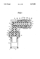
- FIG. is a sectioned side view of the inventive angled connector.
- inventive connector has first end 1, adapted to receive a cable, and second end 2 for engaging a fixed mating connector (not shown). Center line 3 of first end 1 intersects center line 4 of second end 2 at an angle.
- first end 1 and second end 2 Electrical continuity between first end 1 and second end 2 is provided by center contact 5 surrounded by insulator 6. Both center contact 5 and insulator 6 are, in turn, encased in outer body 7.
- First end 1 comprises a subassembly which is adapted to receive a cable (not shown) and comprises sleeve 8, first core portion 9 and second core portion 10.
- the cable is inserted into first end 1 so that the exposed center contact of the cable is disposed within second core portion 10, and contacts center contact 5.
- the cable insulator fits within first core portion 9, with the outer contact of the cable positioned around the outside thereof.
- sleeve 8 is crimped to hold the cable firmly in place.
- First end 1 is mounted within flanged portion 11 of outer body 7, and is held in place within flanged portion 11 by C-ring 12 Applying a force against C-ring 12 is spring washer 13.
- the combination of C-ring 12 and spring washer 13 securely hold first end 1 within flanged portion 11 of outer body 7, while allowing first end 1 to rotate freely.
- O-ring 14 made of a resilient material can be incorporated into the assembly.
- Second end 2 is attached to outer body 7, in a similar manner as described with first end 1.
- Second end 2 comprising a subassembly including intermediate contact 18 and inner body 19 is inserted into outer body 7, and held in place by a combination of second C-ring 15 and second spring washer 16.
- Second O-ring 17 can also be provided to insure a moisture-proof seal between said end 2 and outer body 7.
- Second end 2 terminates with intermediate contact 18 and center contact 5, the combination of which, establishes electric contact with the fixed mating connector to which it is attached. (Not shown).
- coupling nut 20 adapted to screw onto the fixed mating connector to attach the inventive connector thereto.
- Coupling nut 20 is maintained in position around inner body 19 by third C-ring 21 which, while maintaining coupling nut 20 in position around inner body 19, allows coupling nut 20 to rotate freely.
- Inner gasket 22 can also be provided to further moisture-proof the assembly. The use of C-rings to hold both coupling nut 20 to inner body 19, and first end 1 and second end 2 to outer body 7, allowing both the first and second ends to remain free to rotate around center lines 3 and 4, respectively.
- first end center line 3 and second end center line 2 are formed between first end center line 3 and second end center line 2.
- the above-described connector allows free independent rotation of the perpendicular first and second connector ends.
- the inventive connector further provides electrical signal integrity and minimal signal noise during this rotation.
Abstract
Description
Claims (6)
Priority Applications (1)
| Application Number | Priority Date | Filing Date | Title |
|---|---|---|---|
| US07/861,467 US5277590A (en) | 1992-04-01 | 1992-04-01 | Swiveling angled cable connector |
Applications Claiming Priority (1)
| Application Number | Priority Date | Filing Date | Title |
|---|---|---|---|
| US07/861,467 US5277590A (en) | 1992-04-01 | 1992-04-01 | Swiveling angled cable connector |
Publications (1)
| Publication Number | Publication Date |
|---|---|
| US5277590A true US5277590A (en) | 1994-01-11 |
Family
ID=25335881
Family Applications (1)
| Application Number | Title | Priority Date | Filing Date |
|---|---|---|---|
| US07/861,467 Expired - Lifetime US5277590A (en) | 1992-04-01 | 1992-04-01 | Swiveling angled cable connector |
Country Status (1)
| Country | Link |
|---|---|
| US (1) | US5277590A (en) |
Cited By (19)
| Publication number | Priority date | Publication date | Assignee | Title |
|---|---|---|---|---|
| US5704809A (en) * | 1995-07-26 | 1998-01-06 | The Whitaker Corporation | Coaxial electrical connector |
| US5882226A (en) * | 1996-07-08 | 1999-03-16 | Amphenol Corporation | Electrical connector and cable termination system |
| US5971770A (en) * | 1997-11-05 | 1999-10-26 | Labinal Components And Systems, Inc. | Coaxial connector with bellows spring portion or raised bump |
| WO2000024092A1 (en) * | 1998-10-19 | 2000-04-27 | Channell Commercial Europe Limited | Electrical connector |
| GB2371152A (en) * | 2001-01-15 | 2002-07-17 | Volex Group Plc | A swivelable housing and contact assembly |
| US20020177358A1 (en) * | 2001-05-22 | 2002-11-28 | Jean-Marc Baffert | Angled coaxial electrical connector device |
| US20030073328A1 (en) * | 2001-01-12 | 2003-04-17 | Driscoll Michael P. | Interconnection system |
| US6945805B1 (en) | 2004-11-02 | 2005-09-20 | Lester Bollinger | Self-locking rotatable electrical coupling |
| US6979202B2 (en) | 2001-01-12 | 2005-12-27 | Litton Systems, Inc. | High-speed electrical connector |
| FR2950201A1 (en) * | 2009-09-11 | 2011-03-18 | Snecma | Electrical lead conductors connecting device for airplane engine, has electrical conductive slip ring mounted between tubular body and cylindrical sleeve to ensure electrical continuity between body and sleeve |
| US20120322275A1 (en) * | 2011-06-16 | 2012-12-20 | Li Chin-Lai | Rotatable coaxial adaptor for linking high frequency coaxial cables |
| US20130203288A1 (en) * | 2012-02-03 | 2013-08-08 | Robert C. Hosler, Sr. | Coaxial angled adapter |
| US20140322972A1 (en) * | 2004-11-24 | 2014-10-30 | Ppc Broadband, Inc. | Connector having a grounding member |
| US20150008897A1 (en) * | 2013-07-03 | 2015-01-08 | Dr. Johannes Heidenhain Gmbh | Scanning unit for scanning a scale and position-measuring device |
| US8968023B1 (en) * | 2013-08-08 | 2015-03-03 | Williamsrdm, Inc. | Rotatable wiring harness for cable and method |
| US8992250B1 (en) | 2013-03-15 | 2015-03-31 | Megaphase, Llc | Clockable cable adapter |
| US9660379B1 (en) | 2016-05-18 | 2017-05-23 | Ford Global Technologies, Llc | Vehicle electrical connector assembly and connection method |
| US20180331477A1 (en) * | 2017-05-15 | 2018-11-15 | Canare Electric Co., Ltd. | Adaptor |
| US11456566B2 (en) * | 2020-03-05 | 2022-09-27 | Applied Optoelectronics, Inc. | Coaxial connector seizure assembly with integrated mechanical stop and a hybrid fiber-coaxial (HFC) module implementing same |
Citations (8)
| Publication number | Priority date | Publication date | Assignee | Title |
|---|---|---|---|---|
| US2452168A (en) * | 1945-03-01 | 1948-10-26 | Chiksan Tool Company | Swivel type coaxial connector |
| US2641744A (en) * | 1945-05-11 | 1953-06-09 | Packh David C De | Coupling device for relatively rotatable coaxial cables |
| US2813144A (en) * | 1950-12-20 | 1957-11-12 | Amphenol Electronics Corp | Coaxial angle connector |
| US3229234A (en) * | 1963-07-18 | 1966-01-11 | Sage Laboratories | Coaxial rotary joint with spring blased sliding contact ring |
| US3483307A (en) * | 1966-11-07 | 1969-12-09 | Scientific Atlanta | Rotary joint utilizing a fluid slip ring |
| US3847463A (en) * | 1973-04-11 | 1974-11-12 | Gilbert Engineering Co | Cable connector apparatus |
| US4336974A (en) * | 1978-11-13 | 1982-06-29 | Microwave Development Labs. Inc. | Coaxial rotary joint |
| US5122063A (en) * | 1991-02-06 | 1992-06-16 | Alliance Research Corporation | Adjustable electrical connector |
-
1992
- 1992-04-01 US US07/861,467 patent/US5277590A/en not_active Expired - Lifetime
Patent Citations (8)
| Publication number | Priority date | Publication date | Assignee | Title |
|---|---|---|---|---|
| US2452168A (en) * | 1945-03-01 | 1948-10-26 | Chiksan Tool Company | Swivel type coaxial connector |
| US2641744A (en) * | 1945-05-11 | 1953-06-09 | Packh David C De | Coupling device for relatively rotatable coaxial cables |
| US2813144A (en) * | 1950-12-20 | 1957-11-12 | Amphenol Electronics Corp | Coaxial angle connector |
| US3229234A (en) * | 1963-07-18 | 1966-01-11 | Sage Laboratories | Coaxial rotary joint with spring blased sliding contact ring |
| US3483307A (en) * | 1966-11-07 | 1969-12-09 | Scientific Atlanta | Rotary joint utilizing a fluid slip ring |
| US3847463A (en) * | 1973-04-11 | 1974-11-12 | Gilbert Engineering Co | Cable connector apparatus |
| US4336974A (en) * | 1978-11-13 | 1982-06-29 | Microwave Development Labs. Inc. | Coaxial rotary joint |
| US5122063A (en) * | 1991-02-06 | 1992-06-16 | Alliance Research Corporation | Adjustable electrical connector |
Cited By (33)
| Publication number | Priority date | Publication date | Assignee | Title |
|---|---|---|---|---|
| US5704809A (en) * | 1995-07-26 | 1998-01-06 | The Whitaker Corporation | Coaxial electrical connector |
| US5882226A (en) * | 1996-07-08 | 1999-03-16 | Amphenol Corporation | Electrical connector and cable termination system |
| US5971770A (en) * | 1997-11-05 | 1999-10-26 | Labinal Components And Systems, Inc. | Coaxial connector with bellows spring portion or raised bump |
| WO2000024092A1 (en) * | 1998-10-19 | 2000-04-27 | Channell Commercial Europe Limited | Electrical connector |
| AU749374B2 (en) * | 1998-10-19 | 2002-06-27 | Channell Commercial Europe Limited | Electrical connector |
| US20060019507A1 (en) * | 2001-01-12 | 2006-01-26 | Litton Systems, Inc. | High speed electrical connector |
| US20060292932A1 (en) * | 2001-01-12 | 2006-12-28 | Winchester Electronics Corporation | High-speed electrical connector |
| US20030073328A1 (en) * | 2001-01-12 | 2003-04-17 | Driscoll Michael P. | Interconnection system |
| US7101191B2 (en) | 2001-01-12 | 2006-09-05 | Winchester Electronics Corporation | High speed electrical connector |
| US6910897B2 (en) | 2001-01-12 | 2005-06-28 | Litton Systems, Inc. | Interconnection system |
| US7019984B2 (en) | 2001-01-12 | 2006-03-28 | Litton Systems, Inc. | Interconnection system |
| US6979202B2 (en) | 2001-01-12 | 2005-12-27 | Litton Systems, Inc. | High-speed electrical connector |
| GB2371152A (en) * | 2001-01-15 | 2002-07-17 | Volex Group Plc | A swivelable housing and contact assembly |
| US6641436B2 (en) * | 2001-05-22 | 2003-11-04 | Radiall | Angled coaxial electrical connector device |
| US20020177358A1 (en) * | 2001-05-22 | 2002-11-28 | Jean-Marc Baffert | Angled coaxial electrical connector device |
| US6945805B1 (en) | 2004-11-02 | 2005-09-20 | Lester Bollinger | Self-locking rotatable electrical coupling |
| US20140322972A1 (en) * | 2004-11-24 | 2014-10-30 | Ppc Broadband, Inc. | Connector having a grounding member |
| US8882538B1 (en) * | 2004-11-24 | 2014-11-11 | Ppc Broadband, Inc. | Connector having a coupler-to-body grounding member |
| US8876550B1 (en) * | 2004-11-24 | 2014-11-04 | Ppc Broadband, Inc. | Connector having a grounding member |
| US20140322944A1 (en) * | 2004-11-24 | 2014-10-30 | Ppc Broadband, Inc. | Connector having a coupler-to-body grounding member |
| FR2950201A1 (en) * | 2009-09-11 | 2011-03-18 | Snecma | Electrical lead conductors connecting device for airplane engine, has electrical conductive slip ring mounted between tubular body and cylindrical sleeve to ensure electrical continuity between body and sleeve |
| US8512047B2 (en) * | 2011-06-16 | 2013-08-20 | Chin-Lai LI | Rotatable coaxial adaptor for linking high frequency coaxial cables |
| US20120322275A1 (en) * | 2011-06-16 | 2012-12-20 | Li Chin-Lai | Rotatable coaxial adaptor for linking high frequency coaxial cables |
| US20130203288A1 (en) * | 2012-02-03 | 2013-08-08 | Robert C. Hosler, Sr. | Coaxial angled adapter |
| US9054471B2 (en) * | 2012-02-03 | 2015-06-09 | Megaphase, Llc | Coaxial angled adapter |
| US9431780B2 (en) | 2012-02-03 | 2016-08-30 | Megaphase, Llc | Coaxial adapter with an adapter body forward projecting member |
| US8992250B1 (en) | 2013-03-15 | 2015-03-31 | Megaphase, Llc | Clockable cable adapter |
| US20150008897A1 (en) * | 2013-07-03 | 2015-01-08 | Dr. Johannes Heidenhain Gmbh | Scanning unit for scanning a scale and position-measuring device |
| US10527399B2 (en) * | 2013-07-03 | 2020-01-07 | Dr. Johannes Heidenhain Gmbh | Scanning unit for scanning a scale and position-measuring device |
| US8968023B1 (en) * | 2013-08-08 | 2015-03-03 | Williamsrdm, Inc. | Rotatable wiring harness for cable and method |
| US9660379B1 (en) | 2016-05-18 | 2017-05-23 | Ford Global Technologies, Llc | Vehicle electrical connector assembly and connection method |
| US20180331477A1 (en) * | 2017-05-15 | 2018-11-15 | Canare Electric Co., Ltd. | Adaptor |
| US11456566B2 (en) * | 2020-03-05 | 2022-09-27 | Applied Optoelectronics, Inc. | Coaxial connector seizure assembly with integrated mechanical stop and a hybrid fiber-coaxial (HFC) module implementing same |
Similar Documents
| Publication | Publication Date | Title |
|---|---|---|
| US5277590A (en) | Swiveling angled cable connector | |
| US4568145A (en) | Connection device for a cable incorporating optical fibers and metal conductors | |
| US5046964A (en) | Hybrid connector | |
| US3994552A (en) | Submersible pipe electrical cable assembly | |
| US5877452A (en) | Coaxial cable connector | |
| US4168921A (en) | Cable connector or terminator | |
| US4795360A (en) | Electrical cable connector for use in a nuclear environment | |
| US4531798A (en) | Heavy-duty electrical connector | |
| EP0018132B1 (en) | Coaxial electrical connector incorporating a tubular filter | |
| US5938474A (en) | Connector assembly for a coaxial cable | |
| US5219299A (en) | Resistor coupled T-type BNC connector | |
| JPS60218777A (en) | Floating connector assembly | |
| CA2113518A1 (en) | Electrical Connector Fitting | |
| US5890922A (en) | Electrical connector | |
| JP2008504648A (en) | Nut seal assembly for coaxial connectors | |
| US4730385A (en) | Coax connector installation tool | |
| US4333697A (en) | Adapter for a coaxial connector | |
| US4865558A (en) | Stabilizing bushing for electrical connector | |
| US5026302A (en) | Connector | |
| EP0008603A1 (en) | Line coupler for connecting two electrical leads | |
| US4192964A (en) | Modifiable stop element for cable connector assemblies | |
| US5226841A (en) | Clamping device for making an electrical connection | |
| US5842891A (en) | External ground isolation connector for cable splice closures | |
| US4050773A (en) | Battery terminal connector | |
| US5594213A (en) | Wire splice |
Legal Events
| Date | Code | Title | Description |
|---|---|---|---|
| AS | Assignment |
Owner name: KINGS ELECTRONICS CO., INC. A CORPORATION OF NEW Free format text: ASSIGNMENT OF ASSIGNORS INTEREST.;ASSIGNORS:THOMAS, CHRIS;SALVADOR, VICTOR;REEL/FRAME:006076/0573 Effective date: 19920326 |
|
| STCF | Information on status: patent grant |
Free format text: PATENTED CASE |
|
| FPAY | Fee payment |
Year of fee payment: 4 |
|
| FEPP | Fee payment procedure |
Free format text: PAYOR NUMBER ASSIGNED (ORIGINAL EVENT CODE: ASPN); ENTITY STATUS OF PATENT OWNER: SMALL ENTITY |
|
| FPAY | Fee payment |
Year of fee payment: 8 |
|
| SULP | Surcharge for late payment |
Year of fee payment: 7 |
|
| REMI | Maintenance fee reminder mailed | ||
| AS | Assignment |
Owner name: WELLS FARGO BUSINESS CREDIT, INC., GEORGIA Free format text: SECURITY AGREEMENT;ASSIGNOR:KINGS ELECTRONICS CO., INC.;REEL/FRAME:014601/0150 Effective date: 20040407 |
|
| FPAY | Fee payment |
Year of fee payment: 12 |
|
| AS | Assignment |
Owner name: KINGS ELECTRONICS CO., INC., SOUTH CAROLINA Free format text: RELEASE BY SECURED PARTY;ASSIGNOR:WELLS FARGO BANK, NATIONAL ASSOCIATION, SUCCESSOR-BY-MERGER TO WELLS FARGO BUSINESS CREDIT, INC., A MINNESOTA CORPORATION;REEL/FRAME:019297/0022 Effective date: 20070508 |
|
| AS | Assignment |
Owner name: NEWSTAR FINANCIAL, INC., MASSACHUSETTS Free format text: SECURITY AGREEMENT;ASSIGNOR:WINCHESTER ELECTRONICS CORPORATION;REEL/FRAME:019304/0347 Effective date: 20070508 |
|
| AS | Assignment |
Owner name: WINCHESTER ELECTRONICS HOLDINGS, LLC, CONNECTICUT Free format text: RELEASE BY SECURED PARTY;ASSIGNOR:NEWSTAR FINANCIAL, INC.;REEL/FRAME:028725/0038 Effective date: 20120725 Owner name: WINCHESTER ELECTRONICS CORPORATION, CONNECTICUT Free format text: RELEASE BY SECURED PARTY;ASSIGNOR:NEWSTAR FINANCIAL, INC.;REEL/FRAME:028725/0038 Effective date: 20120725 Owner name: WINCHESTER HOLDING, INC., CONNECTICUT Free format text: RELEASE BY SECURED PARTY;ASSIGNOR:NEWSTAR FINANCIAL, INC.;REEL/FRAME:028725/0038 Effective date: 20120725 |