US5275706A - Method and apparatus for continuous, carrier-free deflection electrophoresis - Google Patents

Method and apparatus for continuous, carrier-free deflection electrophoresis Download PDF

Info

Publication number
US5275706A
US5275706A US07/981,607 US98160792A US5275706A US 5275706 A US5275706 A US 5275706A US 98160792 A US98160792 A US 98160792A US 5275706 A US5275706 A US 5275706A
Authority
US
United States
Prior art keywords
separation
medium
separation chamber
sample
media
Prior art date
Legal status (The legal status is an assumption and is not a legal conclusion. Google has not performed a legal analysis and makes no representation as to the accuracy of the status listed.)
Expired - Lifetime
Application number
US07/981,607
Inventor
Gerhard Weber
Current Assignee (The listed assignees may be inaccurate. Google has not performed a legal analysis and makes no representation or warranty as to the accuracy of the list.)
Becton Dickinson and Co
Original Assignee
Gerhard Weber
Priority date (The priority date is an assumption and is not a legal conclusion. Google has not performed a legal analysis and makes no representation as to the accuracy of the date listed.)
Filing date
Publication date
Application filed by Gerhard Weber filed Critical Gerhard Weber
Application granted granted Critical
Publication of US5275706A publication Critical patent/US5275706A/en
Assigned to BECTON DICKINSON AND COMPANY reassignment BECTON DICKINSON AND COMPANY ASSIGNMENT OF ASSIGNORS INTEREST (SEE DOCUMENT FOR DETAILS). Assignors: WEBER, GERHARD
Anticipated expiration legal-status Critical
Expired - Lifetime legal-status Critical Current

Links

Images

Classifications

    • GPHYSICS
    • G01MEASURING; TESTING
    • G01NINVESTIGATING OR ANALYSING MATERIALS BY DETERMINING THEIR CHEMICAL OR PHYSICAL PROPERTIES
    • G01N27/00Investigating or analysing materials by the use of electric, electrochemical, or magnetic means
    • G01N27/26Investigating or analysing materials by the use of electric, electrochemical, or magnetic means by investigating electrochemical variables; by using electrolysis or electrophoresis
    • G01N27/416Systems
    • G01N27/447Systems using electrophoresis
    • G01N27/44756Apparatus specially adapted therefor
    • G01N27/44769Continuous electrophoresis, i.e. the sample being continuously introduced, e.g. free flow electrophoresis [FFE]
    • BPERFORMING OPERATIONS; TRANSPORTING
    • B01PHYSICAL OR CHEMICAL PROCESSES OR APPARATUS IN GENERAL
    • B01DSEPARATION
    • B01D57/00Separation, other than separation of solids, not fully covered by a single other group or subclass, e.g. B03C
    • B01D57/02Separation, other than separation of solids, not fully covered by a single other group or subclass, e.g. B03C by electrophoresis

Definitions

  • the present invention relates to a method and apparatus for continuous, carrier-free deflection electrophoresis.
  • FFE separation methods are used to isolate ions of arbitrary molecular weight, including bioparticles, because electrophoretic migration in an electric field is independent of whether a charge is borne by a molecule or a particle and of whether it is acquired by addition or adsorption of foreign ions.
  • the method is used both for preparative and for analytical separation.
  • a separation chamber is illustrated schematically with reference numbers as indicated.
  • an inlet opening 15 which communicates by way of a medium conduit 22 with a reservoir 19 mounted at a higher level. Separation medium can be introduced through this inlet opening 15.
  • conduits 23 and 24 which lead to additional medium containers 20 and 21 by way of a common media pump 25 such as a hose pump.
  • a sample inlet 16 near the inlet end 13 is connected to a sample vessel 26 by way of a sample conduit 27 and a bubble trap 28.
  • membranes 8 are provided which isolate electrodes 11 and 12 from the actual separation space.
  • a plurality of fraction outlets 17a-17n is provided; these outlets communicate with a fraction vessel 29 by way of fraction conduits 30a-30n which pass through a fraction pump 9 such as a hose pump.
  • the media in particular the separation medium and the sample, are introduced into the separation space under gravity, which takes a relatively long time. Furthermore, it is difficult to keep the relative rates of travel constant, which considerably affects the precision of the separation.
  • the fractions are usually collected by means of pumps.
  • a pump must be used that has 90 channels operating completely independently of one another.
  • the volume flow rate is the same in all channels.
  • hose pumps are used, the relative propulsion rates of which are defined by the individual hoses in the individual channels. This means, however, that the volume flows are determined by the inside diameters of the individual hoses. This inside diameter changes in the course of time, which has a considerable influence in systems for long-term operation such as are of interest here.
  • the separation effect of the fractionation is closely related to the time the sample spends in the electric field and hence to the flow velocity in the separation chamber. In a given separation chamber, therefore, the separation effect is limited by the fact that the volume flow in the individual channels of the fractionation pump cannot be made arbitrarily small. Furthermore, as the volume flow decreases, the fluctuations in volume flow increase, which leads to oscillating flow rates in the separation chamber and thus, in turn, to less effective separation.
  • Another problem with conventional FFE is that it is essential to prevent appreciable lowering of the pressure in the separation chamber, because otherwise gas or air bubbles will form and considerably impair the results of the separation process. This problem cannot be entirely solved even by introducing the media (except for one) by means of volumetric-propulsion pumps, because even here the residual pulsations mentioned above reduce the effectiveness of separation.
  • the material used for the hoses in the fractionation pump plays a further role in the process.
  • the only sufficiently soft material for the hoses is silicone; a longer-lasting material such as PTFE is unusable because it is too hard.
  • the present invention is directed to the problem of improving the separation achievable in the long-term operation of apparatus for continuous, carrier-free deflection electrophoresis.
  • a method for continuous, carrier-free deflection electrophoresis comprising the steps of providing a separation chamber through which at least one separation medium as carrier and a sample medium to be investigated flow at a substantially constant delivery rate from an inlet end to an outlet end thereof, generating an electric field by means of electrodes across the separation chamber to separate spatially the sample medium into fractions, and collecting the fractions at a substantially constant outflow rate, and wherein the improvement comprises delivering an additive medium to the separation chamber at a predetermined flow rate in countercurrent to the separation and sample media in order to adjust the outflow rate from the separation chamber in the region of its outlet end.
  • an apparatus for continuous, carrier-free deflection electrophoresis comprising a separation chamber with an inlet end, which defines at least one inlet opening through which a separation medium can be introduced at a substantially constant flow rate and at least one sample inlet through which a sample medium can be introduced at a substantially constant flow rate, and an outlet end, which defines a plurality of fraction outlets to collect fractions of the sample medium at a substantially constant flow rate, electrodes located within the separation chamber, and membranes for the electrodes, and wherein the improvement comprises the provision of of an additive inlet at the outlet end of the separation chamber through which an additive medium can be introduced into the separation chamber so as to flow in countercurrent to the separation and sample media.
  • Fundamental to the present invention is the adjustment of flow and pressure conditions, and hence of the outflow rate of fractions from the separation chamber, by the supply of an additive medium with a predetermined flow rate.
  • This additive medium flows in countercurrent to the separation and sample media so that in the separation chamber the same media flow as previously, namely the separation medium with the sample medium, but during collection of the fractions the additive medium is collected along with them.
  • the flow rate in the separation chamber in the gap
  • the separation effect can thus be considerably enhanced.
  • the additive medium comprises a separation medium.
  • a reagent that reacts with at least one of the fractions, in order to determine the reaction or its result.
  • the addition of the additive medium and the associated increase in flow velocity between the fraction outlet that is the collection point in the separation chamber and a corresponding detector in the fraction conduit ensures a considerable shortening of the delay time.
  • the fraction conduits or hoses can be made of any material and retain their mechanical characteristics throughout long periods of use because they are under no mechanical stress.
  • To fix the volume flow rates of the fractions it is not necessary, as previously, to make the cross-sections of the conduit lumens absolutely identical. Instead, when the present invention is employed it is merely a matter of making the resistances to flow identical, which can be done with tubes of different inside diameters by varying their lengths accordingly.
  • a concomitant result is that a negative pressure can never develop in the separation chamber; on the contrary, there is always a certain amount of excess pressure.
  • substantially constant volume flows of membrane media are introduced into the separation chamber at its periphery in such a way that the membrane surfaces toward the separation chamber lie within the membrane media and are isolated by them from the separation medium and the sample in the rest of the separation space by virtue of the interfaces between the membrane media currents and the separation medium plus sample current which effectively form liquid membranes.
  • Different membrane media are supplied in the anodal and cathodal regions to reduce or suppress the accumulation of ions at one membrane and the depletion of ions at the other membrane.
  • the media keep the membrane properties constant and this is especially important for long-term operation.
  • the conductivities of the membrane media are preferably adjusted to substantially the same values, such as that of the electrode buffer conventionally surrounding the electrodes. In this way a warming of the membranes and of the surrounding regions, with a concomitant change in the electric field, is effectively prevented.
  • FIG. 1 is a diagram showing schematically a first embodiment of the invention
  • FIG. 2 is a diagram, similar to FIG. 1 but showing a second embodiment of the invention.
  • FIG. 3 is a diagram showing schematically a conventional apparatus.
  • a separation chamber 10 comprises an inlet end 13 at the bottom and into it opens a media conduit 22 by way of an inlet opening 15.
  • the media conduit 22 leads to a reservoir 19.
  • a sample inlet 16 Near the inlet end 13 is a sample inlet 16, which is connected to a sample vessel 26 by way of a sample conduit 27.
  • an additive conduit 33 branches off and leads to an outlet end 14 at the top of the separation chamber 10, into which the additive conduit 33 opens by way of an additive inlet 18.
  • sample conduit 27, the separation media conduit 22 and the additive conduit 33 pass through a media pump 25, so that these three media are transported in a precisely equal flow relationship.
  • a bypass conduit 31 with a control valve 32 is provided, so that part of the additive stream propelled forward by the pump can be returned.
  • electrodes 11 and 12 are positioned behind membranes 8.
  • fraction outlets 17a-17n which communicate with a fraction vessel 29 by way of fraction conduits 30a-30n. No pump is provided for these conduits.
  • a reagent container 34 can be provided (indicated in dashed lines), which leads to the additive conduit 33 by way of a control valve 35 and a conduit 36.
  • the necessary driving pressure can be provided by gravity, by an additional volumetric pump or by passing the reagent conduit 36 through the pump 25.
  • the separation medium and the sample are continuously introduced to the separation chamber 10 through the conduits 22 and 27, respectively, by means of the pump 25, so that both media flow toward the outlet end 14.
  • the components of the sample are deflected according to the various charges of the ions or particles and according to their characteristic frictional resistances, on the way to the fraction outlets 17a-17n.
  • an additive medium which in the present case consists of separation medium, is introduced through the conduit 33 and the additive inlet 18 of the separation chamber 10. Because the fraction outlets 17a-17n are situated between the additive inlet 18 and the lower inlets, namely the inlet opening 15 and the sample inlet 16, the additive medium flows in countercurrent to the separation medium and the sample it contains. These two (or three) volume flow entities flow simultaneously through the fraction outlets 17a-17n, the fraction conduits 30a-30n being so dimensioned with respect to diameter and length that the resistances to flow at the fraction outlets 17a-17n are substantially the same. This arrangement ensures that the amount of additive added to the separation medium with the sample it contains, or to its fraction, is substantially the same at all the fraction outlets 17a-17n.
  • This embodiment of the present invention is distinguished from that shown in FIG. 1 by the provision in the peripheral region of the separation chamber 10 of a first and a second membrane media inlet 42 and 43, respectively, which are respectively connected to membrane media containers 39 and 40 by way of respective conduits 37 and 38. All the conduits leading into the separation chamber 10 pass through a pulsation attenuator 41 after leaving the media pump 25.
  • the inlets 42, 43 are arranged in such a way that membrane media currents 44 (indicated by arrows in FIG. 2) develop, which flow through the separation chamber 10 along the membranes 8 and "isolate" the membranes 8 from the remainder of the separation space.
  • stabilization media are introduced, which compensate ion redistribution effects deriving from the known selectivity properties of membranes in ion transport; that is, they prevent the accumulation of ions associated with one of the electrodes 11, 12 at one of the membranes 8 and suppress ion depletion at the other membrane 8, depending on the electrode polarity.
  • the otherwise unavoidable alteration of the membrane properties during prolonged operation of the apparatus is avoided, so that its influence on the separation effectiveness of the method is substantially eliminated.
  • the introduced stabilization or membrane medium at its interface with the remaining content of the separation space forms, so to speak, a liquid membrane and delivers across these two interfaces all the necessary ions in the correct absolute and relative concentration.
  • the chosen stabilization medium will preferably have a conductivity similar to that of the electrode buffer used, so that there is no abrupt change in resistance across the membrane and hence no warming occurs.

Abstract

In carrier-free continuous deflection electrophoresis problems are encountered in the collection of fractions and it is necessary to use hose pumps with a number of channels corresponding to the number of fractions desired. This arrangement is not only elaborate and susceptible to disturbance, for a great variety of reasons, but even more importantly it necessitates a certain minimal flow velocity within the separation chamber. To improve the effectiveness of separation it is proposed by the present invention to adjust the outflow rate from the separation chamber in the region of its outlet end by introducing an additive medium with a predetermined flow rate in countercurrent to the flow direction of the separation and sample media. In this way the time the sample spends in the electric field and hence the corresponding separation effect is considerably increased.

Description

FIELD OF THE INVENTION
The present invention relates to a method and apparatus for continuous, carrier-free deflection electrophoresis.
DESCRIPTION OF THE PRIOR ART
The basic principles of continuous electrophoresis, which employs a liquid carrier, have long been known and have been published, for example in the 1969 Yearbook of the Max Planck Society at pp. 117-137, which also cites additional literature. A commonly used abbreviation for this technique is FFE (free-flow electrophoresis).
FFE separation methods are used to isolate ions of arbitrary molecular weight, including bioparticles, because electrophoretic migration in an electric field is independent of whether a charge is borne by a molecule or a particle and of whether it is acquired by addition or adsorption of foreign ions. The method is used both for preparative and for analytical separation.
In the following, the known methods and the known apparatus are discussed with reference to FIG. 3.
In this drawing, a separation chamber is illustrated schematically with reference numbers as indicated. At an upper inlet end 13 of the separation chamber 10 there is an inlet opening 15, which communicates by way of a medium conduit 22 with a reservoir 19 mounted at a higher level. Separation medium can be introduced through this inlet opening 15. Also opening into the separation chamber 1O at its upper end 13 are conduits 23 and 24, which lead to additional medium containers 20 and 21 by way of a common media pump 25 such as a hose pump.
A sample inlet 16 near the inlet end 13 is connected to a sample vessel 26 by way of a sample conduit 27 and a bubble trap 28.
At the two sides of the separation chamber 10 membranes 8 are provided which isolate electrodes 11 and 12 from the actual separation space.
At the lower outlet end 14 of the separation chamber 10 a plurality of fraction outlets 17a-17n is provided; these outlets communicate with a fraction vessel 29 by way of fraction conduits 30a-30n which pass through a fraction pump 9 such as a hose pump.
The functional principles of this arrangement will now be discussed.
In known methods and apparatus the media, in particular the separation medium and the sample, are introduced into the separation space under gravity, which takes a relatively long time. Furthermore, it is difficult to keep the relative rates of travel constant, which considerably affects the precision of the separation.
In simultaneous fractionation, the fractions are usually collected by means of pumps. Hence if, for example, 90 fractions are desired, a pump must be used that has 90 channels operating completely independently of one another. In this case it is necessary to ensure that the volume flow rate is the same in all channels. For this purpose hose pumps are used, the relative propulsion rates of which are defined by the individual hoses in the individual channels. This means, however, that the volume flows are determined by the inside diameters of the individual hoses. This inside diameter changes in the course of time, which has a considerable influence in systems for long-term operation such as are of interest here. Given the necessarily large number of hoses or fraction channels, even if silicone material of the lowest hardness is used, forces are exerted against the bearings and shafts of the pump that considerably shorten their useful life. Even though the silicone, which is the only material suitable for this purpose, has a small wall thickness it nevertheless gives only a few hours of operation. The resulting continual replacement of the hoses is labor and cost intensive.
The "separation effect" of the fractionation is closely related to the time the sample spends in the electric field and hence to the flow velocity in the separation chamber. In a given separation chamber, therefore, the separation effect is limited by the fact that the volume flow in the individual channels of the fractionation pump cannot be made arbitrarily small. Furthermore, as the volume flow decreases, the fluctuations in volume flow increase, which leads to oscillating flow rates in the separation chamber and thus, in turn, to less effective separation.
Another problem with conventional FFE is that it is essential to prevent appreciable lowering of the pressure in the separation chamber, because otherwise gas or air bubbles will form and considerably impair the results of the separation process. This problem cannot be entirely solved even by introducing the media (except for one) by means of volumetric-propulsion pumps, because even here the residual pulsations mentioned above reduce the effectiveness of separation.
As previously mentioned, the material used for the hoses in the fractionation pump plays a further role in the process. The only sufficiently soft material for the hoses is silicone; a longer-lasting material such as PTFE is unusable because it is too hard.
In the long-term process of interest here, a further problem is presented by changes which occur in the membranes isolating the electrodes from the actual separation space. These effects are especially disturbing when a method of continuous isoelectric focussing is being used.
SUMMARY OF THE INVENTION
The present invention is directed to the problem of improving the separation achievable in the long-term operation of apparatus for continuous, carrier-free deflection electrophoresis.
According to a first aspect of the present invention there is provided a method for continuous, carrier-free deflection electrophoresis, comprising the steps of providing a separation chamber through which at least one separation medium as carrier and a sample medium to be investigated flow at a substantially constant delivery rate from an inlet end to an outlet end thereof, generating an electric field by means of electrodes across the separation chamber to separate spatially the sample medium into fractions, and collecting the fractions at a substantially constant outflow rate, and wherein the improvement comprises delivering an additive medium to the separation chamber at a predetermined flow rate in countercurrent to the separation and sample media in order to adjust the outflow rate from the separation chamber in the region of its outlet end.
According to a second aspect of the present invention there is provided an apparatus for continuous, carrier-free deflection electrophoresis comprising a separation chamber with an inlet end, which defines at least one inlet opening through which a separation medium can be introduced at a substantially constant flow rate and at least one sample inlet through which a sample medium can be introduced at a substantially constant flow rate, and an outlet end, which defines a plurality of fraction outlets to collect fractions of the sample medium at a substantially constant flow rate, electrodes located within the separation chamber, and membranes for the electrodes, and wherein the improvement comprises the provision of of an additive inlet at the outlet end of the separation chamber through which an additive medium can be introduced into the separation chamber so as to flow in countercurrent to the separation and sample media.
Fundamental to the present invention is the adjustment of flow and pressure conditions, and hence of the outflow rate of fractions from the separation chamber, by the supply of an additive medium with a predetermined flow rate. This additive medium flows in countercurrent to the separation and sample media so that in the separation chamber the same media flow as previously, namely the separation medium with the sample medium, but during collection of the fractions the additive medium is collected along with them. In this way, the flow rate in the separation chamber (in the gap) can, in principle, be made arbitrarily low, even though continuous collection of "fractions" (in this case, of course, at lower concentrations) occurs. The separation effect can thus be considerably enhanced.
It is advantageous for the additive medium to comprise a separation medium. To it can be added a reagent that reacts with at least one of the fractions, in order to determine the reaction or its result. The addition of the additive medium and the associated increase in flow velocity between the fraction outlet that is the collection point in the separation chamber and a corresponding detector in the fraction conduit ensures a considerable shortening of the delay time.
All the media are introduced by way of volumetric-propulsion pumps such as hose pumps, whereas collection is a purely passive process, without a fraction pump. Hence, a multichannel hose pump with all the problems described above is no longer required. When the present invention is employed, the fraction conduits or hoses can be made of any material and retain their mechanical characteristics throughout long periods of use because they are under no mechanical stress. To fix the volume flow rates of the fractions it is not necessary, as previously, to make the cross-sections of the conduit lumens absolutely identical. Instead, when the present invention is employed it is merely a matter of making the resistances to flow identical, which can be done with tubes of different inside diameters by varying their lengths accordingly. A concomitant result is that a negative pressure can never develop in the separation chamber; on the contrary, there is always a certain amount of excess pressure.
Another subsidiary aspect of the present invention, which can also be applied with the same advantages to conventional FFE methods or FFE apparatus, substantially constant volume flows of membrane media are introduced into the separation chamber at its periphery in such a way that the membrane surfaces toward the separation chamber lie within the membrane media and are isolated by them from the separation medium and the sample in the rest of the separation space by virtue of the interfaces between the membrane media currents and the separation medium plus sample current which effectively form liquid membranes. Different membrane media are supplied in the anodal and cathodal regions to reduce or suppress the accumulation of ions at one membrane and the depletion of ions at the other membrane. Thus, the media keep the membrane properties constant and this is especially important for long-term operation.
The conductivities of the membrane media are preferably adjusted to substantially the same values, such as that of the electrode buffer conventionally surrounding the electrodes. In this way a warming of the membranes and of the surrounding regions, with a concomitant change in the electric field, is effectively prevented.
BRIEF DESCRIPTION OF THE DRAWINGS
FIG. 1 is a diagram showing schematically a first embodiment of the invention;
FIG. 2 is a diagram, similar to FIG. 1 but showing a second embodiment of the invention; and
FIG. 3 is a diagram showing schematically a conventional apparatus.
DESCRIPTION OF THE PREFERRED EMBODIMENTS
In the following description, the same reference numbers are used for the same components and those with the same function which occur in the embodiments described with reference to both FIG. 1 and FIG. 2 as well as those previously described with reference to FIG. 3.
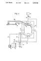
In the embodiment of the invention shown in FIG. 1, a separation chamber 10 comprises an inlet end 13 at the bottom and into it opens a media conduit 22 by way of an inlet opening 15. The media conduit 22 leads to a reservoir 19.
Near the inlet end 13 is a sample inlet 16, which is connected to a sample vessel 26 by way of a sample conduit 27.
From the media conduit 22, an additive conduit 33 branches off and leads to an outlet end 14 at the top of the separation chamber 10, into which the additive conduit 33 opens by way of an additive inlet 18.
The sample conduit 27, the separation media conduit 22 and the additive conduit 33 pass through a media pump 25, so that these three media are transported in a precisely equal flow relationship.
To adjust the flow of the additive medium, in the embodiment illustrated here, a bypass conduit 31 with a control valve 32 is provided, so that part of the additive stream propelled forward by the pump can be returned.
In the separation chamber 10, as in conventional apparatus, electrodes 11 and 12 are positioned behind membranes 8.
Near the upper outlet end 14 there are fraction outlets 17a-17n, which communicate with a fraction vessel 29 by way of fraction conduits 30a-30n. No pump is provided for these conduits.
In the embodiment shown here, a reagent container 34 can be provided (indicated in dashed lines), which leads to the additive conduit 33 by way of a control valve 35 and a conduit 36. The necessary driving pressure can be provided by gravity, by an additional volumetric pump or by passing the reagent conduit 36 through the pump 25.
In operation, the separation medium and the sample are continuously introduced to the separation chamber 10 through the conduits 22 and 27, respectively, by means of the pump 25, so that both media flow toward the outlet end 14. As the flowing media pass through the electric field generated by electrodes 11 and 12, the components of the sample are deflected according to the various charges of the ions or particles and according to their characteristic frictional resistances, on the way to the fraction outlets 17a-17n.
At the same time, an additive medium which in the present case consists of separation medium, is introduced through the conduit 33 and the additive inlet 18 of the separation chamber 10. Because the fraction outlets 17a-17n are situated between the additive inlet 18 and the lower inlets, namely the inlet opening 15 and the sample inlet 16, the additive medium flows in countercurrent to the separation medium and the sample it contains. These two (or three) volume flow entities flow simultaneously through the fraction outlets 17a-17n, the fraction conduits 30a-30n being so dimensioned with respect to diameter and length that the resistances to flow at the fraction outlets 17a-17n are substantially the same. This arrangement ensures that the amount of additive added to the separation medium with the sample it contains, or to its fraction, is substantially the same at all the fraction outlets 17a-17n. This in turn means that, given a constant volume flow (volume per unit time) through the fraction conduits 30a-30n, the flow velocity through the separation chamber 10 between the electrodes 11,12 can be made high or low, depending on the volume flow of the additive in relation to the sum of the other volume flows. The time the "sample elements" spend in the electric field, and thus the precision of separation, can be adjusted in this way. This is especially important in the case of continuous isoelectric focussing, in which the flow rates are lower by about a factor of 5 than in the case of the FF-zone electrophoresis that has previously been employed almost exclusively.
By the addition of the additive medium in countercurrent, it is possible to avoid excessively small cross-sectional areas or excessive length of the fraction conduits 30a-30n, so that there is no danger of obstruction in hoses with inadequate inside diameters when precipitation or aggregation of the sample or its components occurs. A large "dead" volume in the fractionation apparatus can also be avoided in this way. In contrast, even with the lowest flow rates in the separation space a fractionation apparatus with favorable lumen and length of the hose elements can be used, so that rapid on-line detection is combined with control of the separation process to achieve a "stationary" separation profile in long-term experiments.
The introduction of a reagent, by the means 34-36, together with the additive medium so that it also flows in countercurrent, keeps the reagent from contacting the sample fraction until the latter has almost reached the fraction outlets 17a-17n. In this way there is no interference with fractionation in the electric field but a reaction or the reaction product can be detected with suitable apparatus just before (or after) the fraction outlet.
If one compares the apparatus in accordance with the invention as shown in FIG. 1 with conventional apparatus as shown in FIG. 3, a first difference that is immediately obvious is that the invention eliminates the multichannel pump 9, which amounts to a considerable simplification. A further difference is that a low pressure can never develop within the separation chamber 10.
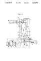
A second embodiment of the present invention will now be described with reference to FIG. 2.
This embodiment of the present invention is distinguished from that shown in FIG. 1 by the provision in the peripheral region of the separation chamber 10 of a first and a second membrane media inlet 42 and 43, respectively, which are respectively connected to membrane media containers 39 and 40 by way of respective conduits 37 and 38. All the conduits leading into the separation chamber 10 pass through a pulsation attenuator 41 after leaving the media pump 25.
The inlets 42, 43 are arranged in such a way that membrane media currents 44 (indicated by arrows in FIG. 2) develop, which flow through the separation chamber 10 along the membranes 8 and "isolate" the membranes 8 from the remainder of the separation space. Through these membrane media inlets 42, 43 stabilization media are introduced, which compensate ion redistribution effects deriving from the known selectivity properties of membranes in ion transport; that is, they prevent the accumulation of ions associated with one of the electrodes 11, 12 at one of the membranes 8 and suppress ion depletion at the other membrane 8, depending on the electrode polarity. As a result, the otherwise unavoidable alteration of the membrane properties during prolonged operation of the apparatus is avoided, so that its influence on the separation effectiveness of the method is substantially eliminated.
The introduced stabilization or membrane medium at its interface with the remaining content of the separation space forms, so to speak, a liquid membrane and delivers across these two interfaces all the necessary ions in the correct absolute and relative concentration. The chosen stabilization medium will preferably have a conductivity similar to that of the electrode buffer used, so that there is no abrupt change in resistance across the membrane and hence no warming occurs.
The method modified in this way (or the apparatus thus modified) is particularly advantageous for the application of isoelectric focussing, where previously selective ion transport at conventional membrane partitions caused extreme interference. At this juncture it should also be mentioned that this particular embodiment of the invention is also suitable for application to apparatus as shown in FIG. 1, in which the same problem occurs. This modification is thus a solution, in accordance with the invention, of one of the problems discussed initially and can be employed independently or as a supplementary measure.
It can be seen from the above that the method and apparatus in accordance with the invention offer many advantages because of the elimination of the fraction pump that was previously required. One of them is that this feature makes sterile operation possible by a simple means, since sterile filters can be provided on the pressure side of the apparatus.

Claims (14)

What is claimed is:
1. A method for continuous, carrier-free deflection electrophoresis, comprising the steps of
providing a separation chamber through which at least one separation medium as carrier and a sample medium to be investigated flow at a substantially constant delivery rate from an inlet end to an outlet end thereof,
generating an electric field by means of electrodes across the separation chamber to separate spatially the sample medium into fractions, and
collecting the fractions at a substantially constant outflow rate, and wherein the improvement comprises
delivering an additive medium to the separation chamber at a predetermined flow rate in countercurrent to the separation and sample media in order to adjust the outflow rate from the separation chamber in the region of its outlet end.
2. A method as claimed in claim 1, wherein the additive medium is the same as the separation medium.
3. A method as claimed in claim 1, comprising the additional step of adding to the additive medium at least one reagent, which reacts with at least one of the fractions, so that at least one of the reaction and its result can be detected.
4. A method as claimed in claim 1, wherein the delivery of all media to the separation chamber is by means of a volumetric-propulsion pump.
5. A method as claimed in claim 1, wherein isolation membranes are provided for the electrodes and the method comprises the additional step of introducing substantially constant volume flows of membrane media into the separation chamber at its periphery in such a way that the membrane surfaces toward the separation chamber lie within the membrane media and are isolated by them from the separation medium and the sample medium in the rest of the separation space by virtue of the interfaces between the membrane media currents and the separation medium plus sample medium current which effectively form liquid membranes, different membrane media being supplied in the anodal and cathodal regions to reduce or suppress the accumulation of ions at one membrane and the depletion of ions at the other membrane.
6. A method as claimed in claim 5, comprising the additional step of adjusting the conductivity of the membrane media so that it is substantially the same as that of an electrode buffer surrounding the electrodes.
7. An apparatus for continuous, carrier-free deflection electrophoresis comprising
a separation chamber with an inlet end, which defines at least one inlet opening through which a separation medium can be introduced at a substantially constant flow rate and at least one sample inlet through which a sample medium can be introduced at a substantially constant flow rate, and an outlet end, which defines a plurality of fraction outlets to collect fractions of the sample medium at a substantially constant flow rate,
electrodes located within the separation chamber, and
membranes for the electrodes,
and wherein the improvement comprises the provision of of an additive inlet at the outlet end of the separation chamber through which an additive medium can be introduced into the separation chamber so as to flow in countercurrent to the separation and sample media.
8. An apparatus as claimed in claim 7, wherein the additive inlet is connected to a conduit for the separation medium which leads to the inlet opening.
9. An apparatus as claimed in claim 7, wherein means are provided to deliver a reagent to the additive inlet.
10. An apparatus as claimed in claim 7, wherein hoses with predetermined flow cross-sections and resistances to flow are connected to the fraction outlets.
11. An apparatus as claimed in claim 7, wherein the separation chamber defines membrane media inlets which open into the separation chamber at its periphery in such a way that membrane media currents can be produced in the peripheral regions of the separation chamber to isolate the membranes from the separation medium and sample medium, the interfaces between the membrane media currents and the separation and sample media current effectively forming liquid membranes.
12. An apparatus as claimed in claim 7, comprising pump means located ahead of the inlet openings and inlets to the separation chamber.
13. An apparatus as claimed in claim 12, wherein the pump means comprises a single multichannel pump.
14. An apparatus as claimed in claim 12, wherein the pump means comprises a multiple-hose pump.
US07/981,607 1991-11-29 1992-11-25 Method and apparatus for continuous, carrier-free deflection electrophoresis Expired - Lifetime US5275706A (en)

Applications Claiming Priority (2)

Application Number Priority Date Filing Date Title
DE4139472A DE4139472C1 (en) 1991-11-29 1991-11-29
DE4139472 1991-11-29

Publications (1)

Publication Number Publication Date
US5275706A true US5275706A (en) 1994-01-04

Family

ID=6445948

Family Applications (1)

Application Number Title Priority Date Filing Date
US07/981,607 Expired - Lifetime US5275706A (en) 1991-11-29 1992-11-25 Method and apparatus for continuous, carrier-free deflection electrophoresis

Country Status (3)

Country Link
US (1) US5275706A (en)
JP (1) JP3242170B2 (en)
DE (1) DE4139472C1 (en)

Cited By (12)

* Cited by examiner, † Cited by third party
Publication number Priority date Publication date Assignee Title
US5562812A (en) * 1995-04-03 1996-10-08 The Penn State Research Foundation Free flow electrophoresis device for biomolecule purification and separation in zero and one G
US20040050697A1 (en) * 2002-01-21 2004-03-18 Christoph Eckerskorn Method and apparatus for executing the method and separation media for separating particles in free flow electrophoresis
US20040050698A1 (en) * 2002-01-21 2004-03-18 Christoph Eckerskorn Apparatus, application of the apparatus and separation media for separating particles in free flow electrophoresis
WO2006118996A3 (en) * 2005-04-29 2007-04-05 Becton Dickinson Co Method for electrophoresis involving parallel and simultaneous separation
US20080237044A1 (en) * 2007-03-28 2008-10-02 The Charles Stark Draper Laboratory, Inc. Method and apparatus for concentrating molecules
US20090044619A1 (en) * 2007-08-13 2009-02-19 Fiering Jason O Devices and methods for producing a continuously flowing concentration gradient in laminar flow
US20090078614A1 (en) * 2007-04-19 2009-03-26 Mathew Varghese Method and apparatus for separating particles, cells, molecules and particulates
US20110005930A1 (en) * 2007-06-20 2011-01-13 Gerhard Weber Ffe media and ffe methods comprising volatile separation media
US20110097718A1 (en) * 2007-11-12 2011-04-28 Becton, Dickinson And Company Ms-compatible nonionic or zwitterionic surfactants in free-flow electrophoresis
US20110174624A1 (en) * 2006-08-29 2011-07-21 Becton, Dickinson And Company Methods and Apparatus for Carrier-Free Deflection Electrophoresis
US9182372B2 (en) 2011-11-22 2015-11-10 Stephen G. Haralampu Stopped-flow, micro-fluidic device and method for the charge-based separation of complex analyte mixtures
US20160238560A1 (en) * 2013-07-04 2016-08-18 Ffe Service Gmbh Free-flow electrophoresis method for separating analytes

Families Citing this family (10)

* Cited by examiner, † Cited by third party
Publication number Priority date Publication date Assignee Title
DE19711898A1 (en) * 1997-03-21 1998-09-24 Gerhard Dr Weber Method and device for carrier-free deflection electrophoresis in interval operation
AU2003201252A1 (en) * 2002-01-21 2003-07-30 Tecan Trading Ag Device, use of said device, and separation agent for separating particles by means of free flow electrophoresis
WO2003060504A1 (en) * 2002-01-21 2003-07-24 Tecan Trading Ag Method, device for carrying out this method, and separating means for separating particles in free-flow electrophoresis
JP2005334865A (en) * 2004-01-19 2005-12-08 Hiroshima Univ Solid particle classifier and solid particle classification method utilizing the same
DE102005020135A1 (en) * 2005-04-29 2006-11-02 Becton, Dickinson And Co. Electrophoresis method, e.g. for separation of ions, involves introducing counter flow media of different properties through counter flow medium inlets into separation chamber
DE102005044994A1 (en) * 2005-09-21 2007-04-05 Gesellschaft zur Förderung der Analytischen Wissenschaften e.V. Device for separating analyte mixture and detecting analyte substances with electrophoretic separation has at least one dielectric separating layer between electrodes for generating electrical field in miniaturized separation chamber
FR2943561B1 (en) * 2009-03-27 2011-05-20 Apr2 METHOD FOR ELECTROSTATIC SEPARATION OF A MIXTURE OF PELLETS OF DIFFERENT MATERIALS AND DEVICE FOR IMPLEMENTING THE SAME
EP3433613A4 (en) * 2016-03-24 2020-05-13 Biological Dynamics, Inc. Disposable fluidic cartridge and components
CN112041067A (en) 2017-12-19 2020-12-04 生物动力学公司 Method and apparatus for detecting multiple analytes from a biological sample
EP3774059A4 (en) 2018-04-02 2022-01-05 Biological Dynamics, Inc. Dielectric materials

Citations (5)

* Cited by examiner, † Cited by third party
Publication number Priority date Publication date Assignee Title
US2878178A (en) * 1955-04-15 1959-03-17 Bier Milan Continuous free-boundary flow electrophoresis
US3519549A (en) * 1963-11-18 1970-07-07 Wolfgang Grassmann Apparatus for performance of carrier-free,continuous electrophoresis in vertical cells
US3869365A (en) * 1972-12-19 1975-03-04 Lkb Produkter Ab Method in counter flow isotachophoresis
US4061560A (en) * 1975-02-28 1977-12-06 Max-Planck-Gesellschaft Zur Forderung Der Wissenschaften E.V. Apparatus for deflection electrophoresis
US4309268A (en) * 1980-08-15 1982-01-05 Mcdonnell Douglas Corporation System for hydrodynamic compensation for electrophoresis crescent distortion

Family Cites Families (1)

* Cited by examiner, † Cited by third party
Publication number Priority date Publication date Assignee Title
DE3742292C1 (en) * 1987-12-14 1989-06-01 Johann Prof Dr-Ing Stichlmair Method and device for two-phase electrophoresis

Patent Citations (5)

* Cited by examiner, † Cited by third party
Publication number Priority date Publication date Assignee Title
US2878178A (en) * 1955-04-15 1959-03-17 Bier Milan Continuous free-boundary flow electrophoresis
US3519549A (en) * 1963-11-18 1970-07-07 Wolfgang Grassmann Apparatus for performance of carrier-free,continuous electrophoresis in vertical cells
US3869365A (en) * 1972-12-19 1975-03-04 Lkb Produkter Ab Method in counter flow isotachophoresis
US4061560A (en) * 1975-02-28 1977-12-06 Max-Planck-Gesellschaft Zur Forderung Der Wissenschaften E.V. Apparatus for deflection electrophoresis
US4309268A (en) * 1980-08-15 1982-01-05 Mcdonnell Douglas Corporation System for hydrodynamic compensation for electrophoresis crescent distortion

Cited By (22)

* Cited by examiner, † Cited by third party
Publication number Priority date Publication date Assignee Title
US5562812A (en) * 1995-04-03 1996-10-08 The Penn State Research Foundation Free flow electrophoresis device for biomolecule purification and separation in zero and one G
US20040050697A1 (en) * 2002-01-21 2004-03-18 Christoph Eckerskorn Method and apparatus for executing the method and separation media for separating particles in free flow electrophoresis
US20040050698A1 (en) * 2002-01-21 2004-03-18 Christoph Eckerskorn Apparatus, application of the apparatus and separation media for separating particles in free flow electrophoresis
US7169278B2 (en) * 2002-01-21 2007-01-30 Tecan Trading Ag Apparatus and separation media for separating particles in free-flow electrophoresis
US7169275B2 (en) * 2002-01-21 2007-01-30 Tecan Trading Ag Method for separating particles in free flow electrophoresis
WO2006118996A3 (en) * 2005-04-29 2007-04-05 Becton Dickinson Co Method for electrophoresis involving parallel and simultaneous separation
CN101184991B (en) * 2005-04-29 2011-12-21 贝克顿·迪金森公司 Method for electrophoresis involving parallel and simultaneous separation
US20110174624A1 (en) * 2006-08-29 2011-07-21 Becton, Dickinson And Company Methods and Apparatus for Carrier-Free Deflection Electrophoresis
US8795494B2 (en) 2006-08-29 2014-08-05 Becton, Dickinson And Company Methods and apparatus for carrier-free deflection electrophoresis
US20080237044A1 (en) * 2007-03-28 2008-10-02 The Charles Stark Draper Laboratory, Inc. Method and apparatus for concentrating molecules
US8679313B2 (en) 2007-03-28 2014-03-25 The Charles Stark Draper Laboratory, Inc. Method and apparatus for concentrating molecules
US20100116657A1 (en) * 2007-03-28 2010-05-13 The Charles Stark Draper Laboratory, Inc. Method and apparatus for concentrating molecules
US8292083B2 (en) 2007-04-19 2012-10-23 The Charles Stark Draper Laboratory, Inc. Method and apparatus for separating particles, cells, molecules and particulates
US20090078614A1 (en) * 2007-04-19 2009-03-26 Mathew Varghese Method and apparatus for separating particles, cells, molecules and particulates
US20110005930A1 (en) * 2007-06-20 2011-01-13 Gerhard Weber Ffe media and ffe methods comprising volatile separation media
US7837379B2 (en) 2007-08-13 2010-11-23 The Charles Stark Draper Laboratory, Inc. Devices for producing a continuously flowing concentration gradient in laminar flow
US20090044619A1 (en) * 2007-08-13 2009-02-19 Fiering Jason O Devices and methods for producing a continuously flowing concentration gradient in laminar flow
US20110097718A1 (en) * 2007-11-12 2011-04-28 Becton, Dickinson And Company Ms-compatible nonionic or zwitterionic surfactants in free-flow electrophoresis
US8449744B2 (en) 2007-11-12 2013-05-28 Becton, Dickinson And Company MS-compatible nonionic or zwitterionic surfactants in free-flow electrophoresis
US9182372B2 (en) 2011-11-22 2015-11-10 Stephen G. Haralampu Stopped-flow, micro-fluidic device and method for the charge-based separation of complex analyte mixtures
US20160238560A1 (en) * 2013-07-04 2016-08-18 Ffe Service Gmbh Free-flow electrophoresis method for separating analytes
US10067089B2 (en) * 2013-07-04 2018-09-04 Ffe Service Gmbh Free-flow electrophoresis method for separating analytes

Also Published As

Publication number Publication date
JPH0663360A (en) 1994-03-08
JP3242170B2 (en) 2001-12-25
DE4139472C1 (en) 1993-03-11

Similar Documents

Publication Publication Date Title
US5275706A (en) Method and apparatus for continuous, carrier-free deflection electrophoresis
US3346479A (en) Preparative separation by a combination of gel separation and electrophoresis
US4315812A (en) Apparatus for continuous electrochromatographic separation
US4662208A (en) Apparatus for the drawing off of untreated and treated dialyzing liquid and/or blood from a dialysis device
US6467630B1 (en) Continuous particle and molecule separation with an annular flow channel
Caldwell et al. Separation of human and animal cells by steric field-flow fractionation
Litzen et al. Separation and quantitation of monoclonal antibody aggregates by asymmetrical flow field-flow fractionation and comparison to gel permeation chromatography
US5736739A (en) Recirculating filtration system for use with a transportable ion mobility spectrometer in gas chromatography applications
US4111785A (en) Apparatus for preparative electrophoresis
US6328868B1 (en) Method for carrier-free deflection electrophoresis
EP1949060B1 (en) Improved multi-capillary viscometer apparatus and method
EP0608120A2 (en) Capillary electrophoresis flow control system
EP0630473A1 (en) Electrical separator apparatus and method of counterflow gradient focusing
US4043895A (en) Electrophoresis apparatus
EP0380605B1 (en) Method and apparatus for flow field flow fractionation
US20130319945A1 (en) Device and Method for Field Flow Fractionation
US4040940A (en) Electrophoretic fractional elution apparatus employing a rotational seal fraction collector
US3498905A (en) Continuous flow electrophoresis apparatus
US4309268A (en) System for hydrodynamic compensation for electrophoresis crescent distortion
US4834862A (en) Ampholyte separation method and apparatus
US3149060A (en) Electrophoresis method and apparatus
JP2005534937A (en) An instrument for separating sample components by liquid chromatography under pressure
US4383905A (en) System for hydrodynamic compensation for electrophoresis crescent distortion
US3451918A (en) Electrophoretic fractionation apparatus
CA1150697A (en) Apparatus for field flow fractionation

Legal Events

Date Code Title Description
STCF Information on status: patent grant

Free format text: PATENTED CASE

FEPP Fee payment procedure

Free format text: PAYOR NUMBER ASSIGNED (ORIGINAL EVENT CODE: ASPN); ENTITY STATUS OF PATENT OWNER: LARGE ENTITY

FPAY Fee payment

Year of fee payment: 4

FPAY Fee payment

Year of fee payment: 8

FEPP Fee payment procedure

Free format text: PAT HOLDER NO LONGER CLAIMS SMALL ENTITY STATUS, ENTITY STATUS SET TO UNDISCOUNTED (ORIGINAL EVENT CODE: STOL); ENTITY STATUS OF PATENT OWNER: LARGE ENTITY

REFU Refund

Free format text: REFUND - PAYMENT OF MAINTENANCE FEE, 12TH YR, SMALL ENTITY (ORIGINAL EVENT CODE: R2553); ENTITY STATUS OF PATENT OWNER: LARGE ENTITY

FPAY Fee payment

Year of fee payment: 12

AS Assignment

Owner name: BECTON DICKINSON AND COMPANY, NEW JERSEY

Free format text: ASSIGNMENT OF ASSIGNORS INTEREST;ASSIGNOR:WEBER, GERHARD;REEL/FRAME:016745/0957

Effective date: 20050502