US5260665A - In-line fluid monitor system and method - Google Patents
In-line fluid monitor system and method Download PDFInfo
- Publication number
- US5260665A US5260665A US07/693,357 US69335791A US5260665A US 5260665 A US5260665 A US 5260665A US 69335791 A US69335791 A US 69335791A US 5260665 A US5260665 A US 5260665A
- Authority
- US
- United States
- Prior art keywords
- fluid
- gas
- loading
- signal
- sensing device
- Prior art date
- Legal status (The legal status is an assumption and is not a legal conclusion. Google has not performed a legal analysis and makes no representation as to the accuracy of the status listed.)
- Expired - Lifetime
Links
Images


Classifications
-
- G—PHYSICS
- G01—MEASURING; TESTING
- G01L—MEASURING FORCE, STRESS, TORQUE, WORK, MECHANICAL POWER, MECHANICAL EFFICIENCY, OR FLUID PRESSURE
- G01L9/00—Measuring steady of quasi-steady pressure of fluid or fluent solid material by electric or magnetic pressure-sensitive elements; Transmitting or indicating the displacement of mechanical pressure-sensitive elements, used to measure the steady or quasi-steady pressure of a fluid or fluent solid material, by electric or magnetic means
- G01L9/0001—Transmitting or indicating the displacement of elastically deformable gauges by electric, electro-mechanical, magnetic or electro-magnetic means
-
- G—PHYSICS
- G01—MEASURING; TESTING
- G01N—INVESTIGATING OR ANALYSING MATERIALS BY DETERMINING THEIR CHEMICAL OR PHYSICAL PROPERTIES
- G01N22/00—Investigating or analysing materials by the use of microwaves or radio waves, i.e. electromagnetic waves with a wavelength of one millimetre or more
Definitions
- the invention relates generally to monitoring fluid in a line without direct fluid contact, and more particularly, relates to non-intrusively monitoring for changes in fluid properties, including the presence of air or other gas, and for fluid pressure.
- continuous in-line monitoring of a fluid is often necessary to ensure consistency of a process or to ensure safety.
- the pressure of fluid in a line may be critical to a process.
- the presence of air or other gas within a fluid or the presence of contaminants within a fluid may need to be monitored. Examples of non-medical applications for fluid monitoring can be found in the chemical process industry, where inexpensive and/or disposable fluid conduits may be required, where fluids may be present at high pressure, or where fluids which are highly caustic or highly toxic may be involved.
- a flow path occlusion can be detected by monitoring the fluid pressure.
- fluid pressure is generally measured either by means of a disposable transducer or by means of a non-disposable transducer coupled with a disposable membrane or other compliant region arranged such that the transducer itself is not in direct contact with the fluid.
- a disposable transducer or specially designed transducer membrane is more expensive than a disposable fluid line alone.
- Air-in-line detection systems are used to prevent the inadvertent infusion of air into a patient's bloodstream. While small bubbles of air may have no adverse effect on a patient, large air bubbles can cause death.
- Methods for the in-line detection of air typically involve ultrasound or light transmission through the fluid line being monitored. The transmission characteristics of sound or light may be utilized as an indication of the presence of a gas bubble in liquid in the fluid line. Simple recognizable perturbations of the signals from such sensors may be utilized to trigger an alarm and/or halt the infusion.
- Such systems require that the fluid and the associated conduit be substantially transparent to the energy being transmitted.
- ultrasonic or optical air-in-line detectors sometimes behave erratically, falsely indicating the presence or absence of air bubbles.
- sensors cannot determine the exact size of air bubbles and are configured merely to indicate the presence of air bubbles which are greater than a predetermined size.
- Electrochemical systems can be extremely sensitive to specific compositional variations in a fluid, but incorporate components, such as membranes, which must be in direct contact with the fluid, thus increasing their costs in applications requiring disposability.
- Laser systems are at present very expensive, and still other systems cannot operate over the wide range of flow rates and fluid types required in many applications.
- the present invention provides for in-line fluid monitoring without direct fluid contact. Detection of fluid properties, including the presence of air or other gas and the indication of changes in fluid composition, as well as the determination of fluid pressure are provided.
- the fluid monitor in accordance with the invention includes the use of a segment of fluid line disposed such that it becomes a part of the dielectric loading of an electromagnetic sensing device. The dielectric loading is monitored to determine the fluid properties such as the composition and pressure of the fluid in the fluid line segment.
- a resonant electromagnetic sensing device is incorporated into an oscillation circuit and the frequency of oscillation is monitored. Changes in that frequency are used to determine fluid pressure and composition, including the presence of air or other gas in the fluid.
- a resonant electromagnetic cavity such as a microwave cavity, is used to encompass a compliant segment of the fluid line. Because the fluid line is compliant, the volume of fluid within the cavity varies in accordance with fluid pressure. The compliant segment and fluid therein are used to form a part of the dielectric loading of the cavity and this dielectric loading is monitored to determine the pressure and composition of the fluid. In circumstances where pressure measurement is not required, the fluid line segment is preferably non-compliant. Circuitry is provided which forms an oscillator whose resonant element is the cavity itself and thus changes in the dielectric loading of the cavity produce variations in the oscillating frequency. Perturbations of the oscillating frequency are monitored and indicate changes in fluid pressure and composition. In one embodiment, the electric field in the cavity is focused on the segment of fluid line encompassed by the cavity so that the fluid line accounts for the major portion of dielectric loading of the cavity.
- a processor is used to compare changes in the oscillating frequency to predetermined parameters to determine the changes in the composition and pressure of the fluid in the segment of the fluid line.
- a look-up table may be provided in the processor so that certain changes in the oscillating frequency may be correlated with fluid composition and pressure and such changes indicated to the user. For example, an inhomogeneity such as a small air bubble presents a markedly different dielectric load than surrounding liquid and thus its presence in the sensor cavity is accompanied by a large shift in the oscillating frequency.
- volumetric flow data of the fluid in the fluid line is furnished. By knowing the volumetric flow rate, the size of the air bubbles in the fluid line can be assessed.
- FIG. 1 shows an exploded, perspective three-dimensional view of a two-port resonant cavity having a fluid line traversing it in accordance with the principles of the invention and having an electric field in a focused region parallel to the fluid line;
- FIG. 2 is an assembled, top sectional view of the resonant cavity of FIG. 1 with the cover removed;
- FIG. 3 is an assembled, side sectional view of the resonant cavity of FIG. 1 taken along lines 3--3 of FIG. 2;
- FIG. 4 is a cross-sectional view of a resonant cavity having a fluid line traversing it such that an electric field in a focused region is parallel to the fluid line;
- FIG. 5 is a diagram of a microstrip resonator with a fluid line segment disposed such that it forms a part of its dielectric load;
- FIG. 6 is a cross-sectional view of a modified stripline resonator with a fluid line segment disposed such that it forms a part of its dielectric load;
- FIG. 7 is a diagram of a fluid line segment disposed so that it forms a part of the dielectric loading of a microstrip delay line;
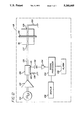
- FIG. 8 is a block/schematic diagram of an in-line fluid monitor system in accordance with the principles of the invention.
- FIG. 9 is a chart of the output voltage of a discriminator versus frequency
- FIG. 10 is a block diagram of an in-line fluid system which includes volumetric flow data of the fluid in a fluid line and an in-line fluid monitor coupled to the same fluid line and a common processor to determine the size of gas bubbles;
- FIG. 11 is a sample graph illustrating the change in oscillating frequency due to changes in concentration of fluid constituents.
- FIG. 12 presents another embodiment of an in-line fluid monitor system utilizing a dielectric resonator oscillator as the signal source.
- FIGS. 1 through 3 a resonant cavity device 10 having a cavity 12 formed by five walls 14 which in this embodiment are formed of an electrically conductive metal such as copper or brass.
- a cover 16 is fitted onto four of the walls 14 to form a sixth wall thereby making cavity 12 a closed cavity.
- the cavity device 10 includes a focusing post 18 placed within the cavity 12 for focusing energy imparted to the cavity into a segment of fluid line 20 which is mounted such that it proceeds through the cavity device 10 and is proximate to the focusing post 18.
- the cover 16, two of the sides 14 and the focusing post 18 have been formed with indentations so that the fluid line 20 can be supported while it proceeds through the cavity device 10.
- These indentations effectively form a channel through the cavity device 10 in which the fluid line segment is disposed.
- the fluid line is compliant and its expansion or contraction must not be hindered due to physical contact with either the focusing post 18 or the cavity cover 16.
- FIGS. 1 though 3 is the use of two probes 22 and 24 which are used to feed energy to and from the cavity 12.
- the probes are coupling loops supported in the cavity 12 by respective cables 26 and 28 or supported by other means.
- An alternative resonant cavity embodiment incorporates a cavity constructed of plastic with metallized inner surfaces.
- Another alternative resonant cavity embodiment incorporates a plastic-filled cavity with metallized outer surfaces and a metallic focusing post electrically connected to the metallized outer surface. In these cases, provision must be made to accommodate the fluid-filled line to be disposed therein as well as the two probes.
- the cavity device 10 forms a resonant cavity 12 energized by a transmitter probe 22.
- the receiver probe 24 couples energy from the cavity for processing as will be described in more detail below.
- Such a cavity will resonate at a frequency dependent upon the cavity size, configuration and the dielectric properties of the "medium" in the cavity 12.
- other resonant characteristics such as bandwidth and Q as well as the impedance of the cavity can be affected by dielectric loading.
- the captured segment of fluid line and fluid therein form a part of the cavity medium and changes occurring in that fluid line and fluid will affect the dielectric properties of the medium.
- changes in the fluid composition and changes in the volume of segment 20 of the fluid line will alter the dielectric loading and cause a consequent change in the resonant characteristics of the cavity 12.
- the transmission probe 22 imparts a small amount of electromagnetic energy (less than one milliwatt) to the cavity at a microwave frequency; for example 5.0 GHz. Because of the transmission probe's geometry, size, location and orientation, when energy is introduced into the cavity at or near its fundamental resonant frequency, the focusing post 18 will cause a localized electric field to be produced in the region between the top of the post 18 and the cover 16. The electric field is focused on the segment of fluid line 20 and the fluid therein. In this embodiment, the cavity structure is such that the fluid line is disposed perpendicular to the electric field.
- One purpose of the focusing post is to cause the fluid line segment 20 to be the major determinant of the dielectric loading of the cavity 12. Small changes in the fluid line 20 and fluid therein will significantly affect the dielectric loading of the cavity. Thus, the sensitivity of the monitor is increased.
- the cavity 12 acts as a filter in that energy at or near particular frequencies, such as the fundamental resonant frequency of the cavity, will be efficiently imparted to the fluid.
- the resonant characteristics of the cavity which is surrounding the fluid line segment filled with a fluid, will remain stable as long as the parameters which are responsible for determining the cavity's resonant characteristics remain constant. However, should the dielectric properties of the fluid within the focused region of the electric field within the cavity change, or the volume of the fluid within the focused region of the electric field change, an accompanying change in resonant characteristics will also occur.
- FIGS. 1 through 3 are for purposes of illustration only and depict a cavity structure wherein the fluid line 20 is disposed perpendicular to the electric field in the focused region.
- FIG. 4 a cross-sectional view of an alternative resonant cavity structure 30 is shown in which the fluid line 20 is disposed parallel to the electric field in the focused region.
- Such a sensor is constructed in a manner which allows the fluid line to be properly installed; for example, the cavity may be split symmetrically along the axis of the fluid line 20 into two halves 32 and 34 and a clamping mechanism (not shown) provided for electrical contact and mechanical stability.
- a cavity is shown as the dielectrically-loaded electromagnetic filter device used, other filter devices may be used.
- a sensor based on the monitoring of dielectric loading, but of lower sensitivity than the cavity type, can be utilized.
- an open planar microstrip or stripline resonant structure can be employed.
- a microstrip resonator device 36 with the resonant microstrip line element 38 supported by the substrate 40, which is backed by the ground plane 42.
- Two microstrip line elements 44 and 46 form the input and output coupling ports.
- the fluid line segment 20 is disposed over the resonant element 38 at or near the region of maximum electric field and thus forms a part of the dielectric loading of the resonator.
- the electric field that is generated has its maximum amplitude at the center of the resonating element 38. Any changes in dielectric loading caused by a change in fluid composition, the presence of air or other gas, or changes in fluid volume will therefore perturb the resonant characteristics in an identifiable manner.
- FIG. 5 illustrates an open microstrip resonator
- a shielded configuration may be used in another embodiment.
- FIG. 6 a modified stripline resonator 48 is illustrated.
- a resonant stripline element 50 is supported by the lower substrate 52, which is backed by a ground plane 54.
- Two stripline elements 56 and 58 form the input and output coupling ports.
- the fluid line segment 20 is disposed over the resonant element 50 at or near the region of maximum electric field and is sandwiched between the lower substrate 52 and the upper substrate 60.
- the upper substrate 60 is backed by a second ground plane 62.
- the two ground planes 54 and 62 together provide greater shielding than in a microstrip structure.
- An appropriate channel must be cut into the upper substrate 60 to accommodate the fluid line segment.
- the fluid line 20 is disposed such that it forms a major part of the dielectric loading of the resonator, changes in the composition and/or pressure of the fluid within will perturb the structure's resonant characteristics.
- a dielectrically-loaded electromagnetic transmission device may be employed as the sensing element rather than a filter device.
- FIG. 7 there is shown a microstrip delay device 64 over which is disposed the fluid line segment 20.
- the transmission element 66 is supported by the substrate 68 which is backed by ground plane 70.
- the fluid line segment 20 is disposed in a manner which allows the electromagnetic field created by the energized transmission element 66 to encompass a significant portion of the fluid line segment.
- the fluid line segment and fluid within form a part of the dielectric loading of the delay device.
- An alternative to the microstrip transmission device would be a modified stripline transmission device.
- the transmission devices do not act as filters, as in the cavity embodiment, they do use the dielectric loading imparted by the fluid line segment and fluid therein and may be used to determine changes in the fluid composition and/or pressure.
- Each fluid possesses particular dielectric properties. When different fluids are mixed together, a new fluid is formed that will probably possess different dielectric properties from the two separate fluids. Moreover, gases, such as air, possess radically different dielectric properties than that of liquids. Water, for example has a dielectric constant approximately eighty times higher than that of air. Thus, referring to the resonant cavity embodiment of FIGS. 1 through 3, the presence of air bubbles in a liquid will cause a radical change in the dielectric loading of the cavity. This change in dielectric properties will cause a significant and identifiable change in the filtering characteristics of the cavity.
- FIG. 8 A schematic/block diagram of an in-line fluid monitor system 72 in accordance with the principles of the invention is shown in FIG. 8.
- the circuit 72 generally comprises three main functional blocks, the sensor oscillator block 74, the discriminator block 76, and the processing block 78.
- the sensor block 74 contains the resonant cavity 12.
- the sensor oscillator block 74 is used to provide a signal representative of the fluid characteristics (e.g., presence of air or other gas in the line, changes in fluid composition, pressure), and comprises a sensor delay element 80 connected to the sensor output cable 28, a bandwidth-limited amplifier 82 connected to the delay element 80, a coupler 84 which receives the output of the amplifier 82 and directs a portion of the output from the amplifier 82 to the input cable 26 of the resonant cavity 12. The coupler 84 also directs a portion of the output from the amplifier 82 to the discriminator circuit 76.
- a circuit is formed in sensor oscillator block 74 wherein the energy of the amplifier is coupled to the resonant cavity 12 via the coupler 84 and the input cable 26 and coupling loop 22.
- the output coupling loop 24 couples energy from the cavity 12 to the delay element 80 and to the input of the amplifier 82.
- the power level in the sensor oscillator block 74 is low (less than one milliwatt in one embodiment) so that the fluid characteristics can be "interrogated" and the fluid not appreciably heated.
- the bandwidth of amplifier 82 is limited such that oscillations in the primary (fundamental) resonant mode of the cavity are sustained and oscillations at higher modes are suppressed.
- the output of the amplifier 82 In order to sustain oscillation, the output of the amplifier 82 must supply positive feedback to its input.
- An additional requirement for oscillation is that the gain of the sensor oscillator block 74, the "loop gain", must be greater than one, that is, the gain in the amplifier must be greater than the sum of the losses of the components in the loop. This gain is sufficient to initiate stable oscillation quite rapidly, on the order of microseconds or less.
- the frequency of the oscillator block is determined primarily by the resonant characteristics of the cavity and the total delay around the loop from amplifier output to amplifier input, as well as the gain of the loop.
- the discriminator block 76 processes the oscillation signal and includes a signal splitter 86 which receives a portion of the output from the sensor amplifier 82 through the coupler 84 and a discriminator input line 88.
- the discriminator signal splitter 86 has an output 90 to a delay element 92 which is connected to one port of a phase detector 94, such as the R.F. port of a double-balanced mixer, and the discriminator signal splitter also has an output 96 which is connected to the L.O. port of the double balanced mixer.
- the output from the double balanced mixer 94 (phase detector) is directed to a low frequency amplifier 98 capable of amplifying signals from D.C. to a frequency consistent with the rate of fluid property changes which are being monitored.
- the amplifier 98 has an output which is provided to the signal processor block 78.
- the discriminator delay element 92 may alternatively be an appropriate phase shifting reactive element, and although the mixer/amplifier arrangement is provided to convert changes in frequency of the sensor oscillator block 74 to changes in voltage, other types of conversion to a signal suitable for analysis by the signal processor block 78 may also be used.
- the delay element 92 is chosen such that the discriminator sensitivity is high in the frequency region of operation.
- the range 100 represents a high sensitivity discrimination frequency sensing range
- the range 102 represents a low sensitivity discrimination frequency sensing range.
- the delay line 92 in the discriminator block 76 is adjusted so that an output of zero volts is produced at the output of the mixer 94. Referring again to FIG. 9, it can be seen that this is the steepest part of the discriminator 76 output, thereby yielding the highest sensitivity.
- the electrical signals supplied by the discriminator block 76 of the in-line fluid monitor 72 must be processed or analyzed in order to determine and quantify important fluid characteristics.
- this task is implemented by a microprocessor included as part of the signal processor 104.
- a microprocessor included as part of the signal processor 104.
- the signal processing requirement of this in-line fluid monitor do not represent a large cost.
- microprocessors perform many computational and control tasks, including communications with the operator of the instrument, allowing the operator to intelligently interact with the instrument in setting desired parameters and limits. Additionally, the microprocessor can easily perform the calculations necessary for "closed loop control", where a desired pressure can be maintained by controlling a pumping mechanism.
- the signal processor 104 receives the electrical output signal from the discriminator block 76, which represents the oscillating frequency of the resonant cavity 12.
- the microprocessor can make determinations based on changes to the oscillating frequency. The existence of a small amount of air in the fluid line segment can be determined by comparing the frequency change to parameters that are either fixed, or "entered in” by the operator of a system which utilizes the in-line fluid monitor.
- the signal processor 104 includes conventional circuitry and programming for comparing the discriminator output voltage signal with a reference value and for determining the magnitude of perturbation of the oscillating frequency.
- the signal processor 104 is also preferably constituted so as to provide an output signal either to a display and/or printer unit 106, such as a display monitor for viewing a real time graph of waveforms of the perturbation of oscillations in the resonant cavity 12, and the signal processor may be adapted to simultaneously generate a signal to an alarm device 108, for indicating an alarm condition when the magnitude of perturbation is greater than a predetermined threshold value.
- the alarm device 108 may aurally indicate an alarm and may also be coupled to the pump controller to automatically stop pump operation.
- a volumetric flow rate data source 110 provides data representative of the volumetric flow rate of the fluid in the fluid line 20 to the signal processor 104.
- the in-line fluid monitor 112 is also coupled to the signal processor 104 for providing fluid property data as described above.
- the volumetric flow rate data is provided by the electronic control system which operates a precision fluid pumping mechanism.
- a flow meter may be provided to provide the flow data, such as that disclosed in U.S. Pat. No. 4,938,079 to Goldberg.
- changes in fluid composition can be detected. Varying concentrations can also be detected as is illustrated in FIG. 11, where varying concentrations of both sodium chloride 114 and dextrose 116 in water produce a change in frequency. Although not shown, radical changes in frequency accompany the presence of a gas in the liquid.
- Another feature of the system is the ability to detect impurities, or contaminants other than air, such as blood.
- impurities or contaminants other than air, such as blood.
- the filtering characteristics of the cavity change.
- Blood has a notably different dielectric character than most common infusates, such as sodium chloride solution, so that if blood were to back up into the administration set, its presence could be detected by observing the perturbation of the oscillation frequency.
- the sensor could detect the perturbation of the cavity loading, assuming the fluids have different dielectric characters, in order to verify that the changeover between fluid types was successful.
- the change in dielectric loading caused by the presence of air in the line is so great, that a system of the type shown in FIG. 8 may cease to oscillate while a large amount of air is within the sensing region of the cavity.
- the range of possible oscillation frequencies at which the system can oscillate depends largely on the bandwidth of the amplifier 82. This bandwidth must be chosen such that oscillation is supported whenever a bubble of a size which the user needs quantified passes through the cavity.
- the signal processor 104 will preferably initiate an alarm 108.
- frequency shifts from 0.1 MHz to 400 MHz have been observed in practice.
- pressure change of the order of ⁇ 300 mm mercury causes oscillating frequency changes in the range of ⁇ 3 MHz.
- This frequency shift is generally less than that caused by the passage of an air bubble of significant size.
- Pressure change can also be distinguished from air bubble passage because the frequency changes due to pressure change are far less abrupt than those caused by air bubble passage.
- the signal processor 104 is programmed to expect a frequency change which is sustained for the duration of the infusion or until a subsequent changeover takes place, rather than a transient change as may take place when the pressure varies.
- FIG. 12 Another embodiment of an in-line fluid monitor system 118 in accordance with the principles of the invention is illustrated in a schematic/block diagram of FIG. 12.
- a stable frequency source 120 such as a dielectric resonator oscillator (D.R.O.) is used, and is shown driving an amplifier 122 the output of which produces sufficient power for sensor operation, for example 10 dBm.
- the power from the amplifier is then fed through a quarter-wavelength directional coupler, such as a microstrip coupler 135, to the input port 137 of a microstrip resonator 36, which may be similar to that described above in relation to FIG. 5.
- the fluid line 20 and fluid therein are positioned to dielectrically load the resonator 36.
- the output port 129 of the resonator 36 is coupled to a signal return through a load 130, which is shown as a fifty ohm resistor in this case.
- the directional coupler 135 is arranged such that it is responsive to the reflected power from the input port 137 of the microstrip resonator 36.
- Proper termination shown to be a fifty ohm resistor 139 in this case, is provided at the terminated port 143 of the directional coupler 135, and the reflected power from the resonator 36 is monitored with a detector, such as a diode detector 132 at the reflected power port 141 of the coupler 135.
- the diode detector 132 may be thought of as a first processor and the signal developed by the detector 132 is amplified 134 and coupled to the signal processor 104.
- the amplitude of the reflected power at port 141 is affected by the dielectric loading on the resonator 36. Changes in that dielectric loading caused by fluid property changes will be detected by detector 132 and provided to the processor 104.
- the arrangement of FIG. 12 may incorporate a rigid fluid line segment 20 over the resonator 36 and can be used to determine the existence of an air bubble in the fluid line.
- the in-line fluid monitor system and method in accordance with the principles of the invention provides a simple, cost effective, and accurate way of detecting fluid properties and pressure.
- the fluid line may be disposable while the monitor system can be reused.
Abstract
Description
Claims (18)
Priority Applications (5)
| Application Number | Priority Date | Filing Date | Title |
|---|---|---|---|
| US07/693,357 US5260665A (en) | 1991-04-30 | 1991-04-30 | In-line fluid monitor system and method |
| EP92107310A EP0511651B1 (en) | 1991-04-30 | 1992-04-29 | In-line fluid monitor system and method |
| DE69216680T DE69216680T2 (en) | 1991-04-30 | 1992-04-29 | Pipe installation fluid monitoring system and method |
| JP4138108A JP2564447B2 (en) | 1991-04-30 | 1992-04-30 | In-pipe fluid monitoring device and method |
| HK98105091A HK1006038A1 (en) | 1991-04-30 | 1998-06-10 | In-line fluid monitor system and method |
Applications Claiming Priority (1)
| Application Number | Priority Date | Filing Date | Title |
|---|---|---|---|
| US07/693,357 US5260665A (en) | 1991-04-30 | 1991-04-30 | In-line fluid monitor system and method |
Publications (1)
| Publication Number | Publication Date |
|---|---|
| US5260665A true US5260665A (en) | 1993-11-09 |
Family
ID=24784322
Family Applications (1)
| Application Number | Title | Priority Date | Filing Date |
|---|---|---|---|
| US07/693,357 Expired - Lifetime US5260665A (en) | 1991-04-30 | 1991-04-30 | In-line fluid monitor system and method |
Country Status (5)
| Country | Link |
|---|---|
| US (1) | US5260665A (en) |
| EP (1) | EP0511651B1 (en) |
| JP (1) | JP2564447B2 (en) |
| DE (1) | DE69216680T2 (en) |
| HK (1) | HK1006038A1 (en) |
Cited By (91)
| Publication number | Priority date | Publication date | Assignee | Title |
|---|---|---|---|---|
| US5455565A (en) * | 1993-11-08 | 1995-10-03 | Ivac Corporation | Fluid monitor system and method using a resonator |
| US5515714A (en) * | 1994-11-17 | 1996-05-14 | General Motors Corporation | Vapor composition and flow sensor |
| EP0721103A1 (en) | 1994-12-28 | 1996-07-10 | Optical Solutions, Inc. | Apparatus for identifying container components using electrical conductivity |
| US5764538A (en) * | 1995-12-04 | 1998-06-09 | Man-Gill Chemical Company | System interface for microwave conductivity sensor |
| US5901633A (en) * | 1996-11-27 | 1999-05-11 | Case Corporation | Method and apparatus for sensing piston position using a dipstick assembly |
| US5927349A (en) * | 1996-12-09 | 1999-07-27 | Baxter International Inc. | Compounding assembly for nutritional fluids |
| US5977778A (en) * | 1996-11-27 | 1999-11-02 | Case Corporation | Method and apparatus for sensing piston position |
| US6005395A (en) * | 1997-11-12 | 1999-12-21 | Case Corporation | Method and apparatus for sensing piston position |
| US6025725A (en) * | 1996-12-05 | 2000-02-15 | Massachusetts Institute Of Technology | Electrically active resonant structures for wireless monitoring and control |
| US6028433A (en) * | 1997-05-14 | 2000-02-22 | Reid Asset Management Company | Portable fluid screening device and method |
| US6142059A (en) * | 1996-11-27 | 2000-11-07 | Case Corporation | Method and apparatus for sensing the orientation of a mechanical actuator |
| US6192752B1 (en) | 1995-08-04 | 2001-02-27 | Zevex, Inc. | Noninvasive electromagnetic fluid level sensor |
| US6199603B1 (en) | 1998-08-14 | 2001-03-13 | Baxter International Inc. | Compounding assembly for nutritional fluids |
| US6204656B1 (en) | 1997-05-29 | 2001-03-20 | Reid Asset Management Company | Miniature sensor for lubricant analysis |
| US6386050B1 (en) * | 1999-12-21 | 2002-05-14 | Agilent Technologies, Inc. | Non-invasive fluid flow sensing based on injected heat tracers and indirect temperature monitoring |
| US6511851B1 (en) | 1997-04-16 | 2003-01-28 | Kaiku Limited | Identifying changes in composition of liquids |
| US6523414B1 (en) | 2001-04-16 | 2003-02-25 | Zevex, Inc. | Optical pressure monitoring system |
| US6531708B1 (en) | 2001-04-16 | 2003-03-11 | Zevex, Inc. | Optical bubble detection system |
| US6566892B2 (en) * | 2000-06-19 | 2003-05-20 | Siemens Vdo Automotive Corporation | Portable fuel analyzer for analyzing the alcohol content of a mixed fuel |
| US6588313B2 (en) | 2001-05-16 | 2003-07-08 | Rosemont Inc. | Hydraulic piston position sensor |
| US6616633B1 (en) * | 1997-09-19 | 2003-09-09 | Alaris Medical Systems, Inc. | Apparatus and method for air-in-line detection |
| US6659976B2 (en) | 2001-04-16 | 2003-12-09 | Zevek, Inc. | Feeding set adaptor |
| US6722260B1 (en) | 2002-12-11 | 2004-04-20 | Rosemount Inc. | Hydraulic piston position sensor |
| US6722261B1 (en) | 2002-12-11 | 2004-04-20 | Rosemount Inc. | Hydraulic piston position sensor signal processing |
| US6725731B2 (en) | 2000-03-08 | 2004-04-27 | Rosemount Inc. | Bi-directional differential pressure flow sensor |
| US6779396B2 (en) * | 2002-04-08 | 2004-08-24 | Takao Tsuda | Method for measuring flow within an open tube |
| US6789458B2 (en) | 2000-03-08 | 2004-09-14 | Rosemount Inc. | System for controlling hydraulic actuator |
| US20040178865A1 (en) * | 2003-03-11 | 2004-09-16 | Snyder Steven Robert | RF delay lines with variable displacement fluidic dielectric |
| US20040207494A1 (en) * | 2003-04-16 | 2004-10-21 | Brown Stephen B. | Continuously tunable waveguide filter |
| US20040207481A1 (en) * | 2003-04-16 | 2004-10-21 | Brown Stephen B. | Continuously tunable waveguide attenuator |
| US6817252B2 (en) | 2000-03-08 | 2004-11-16 | Rosemount Inc. | Piston position measuring device |
| US6848323B2 (en) | 2000-03-08 | 2005-02-01 | Rosemount Inc. | Hydraulic actuator piston measurement apparatus and method |
| US20050093555A1 (en) * | 2003-10-31 | 2005-05-05 | Tdk Corporation | Method of measuring relative dielectric constant of dielectric substance of powders, cavity resonator used in the same, and application apparatus |
| US20060105467A1 (en) * | 2004-11-12 | 2006-05-18 | Niksa Andrew J | MEMS-based sensor for lubricant analysis |
| US20060276748A1 (en) * | 2005-05-17 | 2006-12-07 | Infussafe Llc | Infusion monitoring device system and method |
| US20070078381A1 (en) * | 2002-08-12 | 2007-04-05 | Marc Yap | System and method for blockage detection for medication infusion |
| US20080098798A1 (en) * | 2006-10-24 | 2008-05-01 | Riley Timothy A | Method for making and using an air bubble detector |
| US20080103445A1 (en) * | 2006-09-29 | 2008-05-01 | Blaine David H | Method and Apparatus for Detecting Air Bubbles |
| US7378849B2 (en) | 2003-10-07 | 2008-05-27 | Sra International, Inc. | Method and apparatus for obtaining spatial information and measuring the dielectric constant of an object |
| US7520871B2 (en) | 2002-08-12 | 2009-04-21 | Lma North America, Inc | System and method for tension-activated fluid control |
| US20090101550A1 (en) * | 2007-10-22 | 2009-04-23 | Baxter International Inc. | Dialysis system having non-invasive fluid velocity sensing |
| US20090205441A1 (en) * | 2008-02-14 | 2009-08-20 | Surpass Industry Co., Ltd. | Flow-Rate Measuring Method and Flow-Rate Measuring Device |
| US20100030388A1 (en) * | 2006-09-05 | 2010-02-04 | Chiun Wang | Multi-gas flow device |
| US20100305499A1 (en) * | 2009-03-09 | 2010-12-02 | Leonid Matsiev | Systems and methods for the identification of compounds in medical fluids using admittance spectroscopy |
| US7862875B2 (en) | 2004-10-04 | 2011-01-04 | Trico Corporation | Flinger disc |
| US20110009817A1 (en) * | 2008-03-10 | 2011-01-13 | Bennett James W | Intravenous fluid monitoring |
| US20110109406A1 (en) * | 2008-03-27 | 2011-05-12 | Isis Innovation Limited | Microwave Cavity Sensor |
| US7987722B2 (en) | 2007-08-24 | 2011-08-02 | Zevex, Inc. | Ultrasonic air and fluid detector |
| US8096164B2 (en) | 2008-01-17 | 2012-01-17 | Trico Corporation | Apparatus and methods for management of fluid condition |
| US8147684B2 (en) | 2009-03-27 | 2012-04-03 | Trico Corporation | Apparatus and methods for lubricant filtration and drum pump filtration system |
| US8147683B2 (en) | 2010-01-22 | 2012-04-03 | Trico Corporation | Portable lubricant filtration system and method |
| US20120121469A1 (en) * | 2010-11-11 | 2012-05-17 | Impulse Devices Inc. | Pressurized Acoustic Resonator With Fluid Flow-Through Feature |
| US8220671B2 (en) | 2008-03-12 | 2012-07-17 | Trico Corporation | Lubricant dispenser with nozzle |
| US8303613B2 (en) | 2007-12-07 | 2012-11-06 | Zevex, Inc. | Ultrasonic instrument using langevin type transducers to create transverse motion |
| USD687921S1 (en) | 2012-04-25 | 2013-08-13 | Trico Corporation | Lubricant dispenser |
| USD687923S1 (en) | 2008-06-03 | 2013-08-13 | Trico Corporation | Lubricant dispensing nozzle |
| USD687922S1 (en) | 2012-04-25 | 2013-08-13 | Trico Corporation | Lubricant dispenser |
| US8539812B2 (en) | 2009-02-06 | 2013-09-24 | Zevek, Inc. | Air bubble detector |
| USD696956S1 (en) | 2012-04-25 | 2014-01-07 | Trico Corporation | Lubricant dispenser |
| US8821432B2 (en) | 2012-02-29 | 2014-09-02 | B. Braun Medical Inc. | Split and multiple air bubble sensors for automated infusion systems |
| US8838395B2 (en) | 2010-09-09 | 2014-09-16 | S.E.A. Medical Systems, Inc. | Systems and methods for intravenous drug management using immittance spectroscopy |
| US9052276B2 (en) | 2009-06-08 | 2015-06-09 | S.E.A. Medical Systems, Inc. | Systems and methods for the identification of compounds using admittance spectroscopy |
| US9114217B2 (en) | 2011-08-19 | 2015-08-25 | Hospira, Inc. | Pattern recognition system and method for the detection of stuck fluid droplets in a fluid delivery line of an infusion system |
| US9283332B2 (en) | 2012-02-29 | 2016-03-15 | B. Braun Medical, Inc. | Intelligent air bubble detector and counters for automated infusion systems |
| US20160305917A1 (en) * | 2014-02-27 | 2016-10-20 | Elemental Scientific, Inc. | System for collecting liquid samples |
| KR20170013906A (en) * | 2014-06-07 | 2017-02-07 | 아스실리온 에이비 | A microfabricated sensor and a method of detecting a component in bodily fluid |
| US9995611B2 (en) | 2012-03-30 | 2018-06-12 | Icu Medical, Inc. | Air detection system and method for detecting air in a pump of an infusion system |
| US20180180639A1 (en) * | 2015-06-26 | 2018-06-28 | Elemental Scientific, Inc. | System for collecting liquid samples |
| US10022498B2 (en) | 2011-12-16 | 2018-07-17 | Icu Medical, Inc. | System for monitoring and delivering medication to a patient and method of using the same to minimize the risks associated with automated therapy |
| US10046112B2 (en) | 2013-05-24 | 2018-08-14 | Icu Medical, Inc. | Multi-sensor infusion system for detecting air or an occlusion in the infusion system |
| US10166328B2 (en) | 2013-05-29 | 2019-01-01 | Icu Medical, Inc. | Infusion system which utilizes one or more sensors and additional information to make an air determination regarding the infusion system |
| US10342917B2 (en) | 2014-02-28 | 2019-07-09 | Icu Medical, Inc. | Infusion system and method which utilizes dual wavelength optical air-in-line detection |
| US10430761B2 (en) | 2011-08-19 | 2019-10-01 | Icu Medical, Inc. | Systems and methods for a graphical interface including a graphical representation of medical data |
| US10463788B2 (en) | 2012-07-31 | 2019-11-05 | Icu Medical, Inc. | Patient care system for critical medications |
| US10527473B2 (en) * | 2017-11-21 | 2020-01-07 | National Cheng Kung University | Microwave flowmeter having a transmitting circuit with a plurality of resonator elements generating corresponding microwaves having a resonant frequency |
| US10596316B2 (en) | 2013-05-29 | 2020-03-24 | Icu Medical, Inc. | Infusion system and method of use which prevents over-saturation of an analog-to-digital converter |
| US10635784B2 (en) | 2007-12-18 | 2020-04-28 | Icu Medical, Inc. | User interface improvements for medical devices |
| US10656894B2 (en) | 2017-12-27 | 2020-05-19 | Icu Medical, Inc. | Synchronized display of screen content on networked devices |
| WO2020205301A1 (en) * | 2019-03-29 | 2020-10-08 | President And Fellows Of Harvard College | Subwavelength resonator for acoustophoretic printing |
| US10850024B2 (en) | 2015-03-02 | 2020-12-01 | Icu Medical, Inc. | Infusion system, device, and method having advanced infusion features |
| US11054344B2 (en) | 2014-02-27 | 2021-07-06 | Elemental Scientific, Inc. | System for collecting liquid samples from a distance |
| US11135360B1 (en) | 2020-12-07 | 2021-10-05 | Icu Medical, Inc. | Concurrent infusion with common line auto flush |
| US11246985B2 (en) | 2016-05-13 | 2022-02-15 | Icu Medical, Inc. | Infusion pump system and method with common line auto flush |
| US11278671B2 (en) | 2019-12-04 | 2022-03-22 | Icu Medical, Inc. | Infusion pump with safety sequence keypad |
| US11324888B2 (en) | 2016-06-10 | 2022-05-10 | Icu Medical, Inc. | Acoustic flow sensor for continuous medication flow measurements and feedback control of infusion |
| US11344668B2 (en) | 2014-12-19 | 2022-05-31 | Icu Medical, Inc. | Infusion system with concurrent TPN/insulin infusion |
| US11344673B2 (en) | 2014-05-29 | 2022-05-31 | Icu Medical, Inc. | Infusion system and pump with configurable closed loop delivery rate catch-up |
| CN114607942A (en) * | 2022-04-21 | 2022-06-10 | 国仪量子(合肥)技术有限公司 | Liquid conveying control method and resonant cavity liquid conveying system |
| US11424029B2 (en) | 2010-01-22 | 2022-08-23 | Deka Products Limited Partnership | System, method and apparatus for electronic patient care |
| US11726063B2 (en) * | 2013-07-31 | 2023-08-15 | Deka Products Limited Partnership | Method for bubble detection in a fluid line using a split-ring resonator |
| US11883361B2 (en) | 2020-07-21 | 2024-01-30 | Icu Medical, Inc. | Fluid transfer devices and methods of use |
Families Citing this family (12)
| Publication number | Priority date | Publication date | Assignee | Title |
|---|---|---|---|---|
| DE19651355B4 (en) * | 1996-12-10 | 2004-03-18 | Fresenius Medical Care Deutschland Gmbh | Gas bubble detector |
| GB9901304D0 (en) * | 1999-01-22 | 1999-03-10 | Univ Liverpool | Apparatus and method for determining dielectric properties of an electrically conductive fluid |
| DE10112499B4 (en) | 2001-03-15 | 2010-08-19 | Hauni Maschinenbau Ag | Resonator device, in particular Mikrowellenresonatoreinrichtung |
| ES2199079B2 (en) * | 2002-07-24 | 2005-05-16 | Asm-Dimatec Ingenieria, S.A. | MICROWAVE BUBBLES DETECTOR. |
| ITBO20060585A1 (en) * | 2006-08-03 | 2008-02-04 | Gd Spa | DEVICE FOR THE DETECTION OF A CHARACTERISTIC OF A FIBER MATERIAL. |
| GB0900744D0 (en) * | 2009-01-16 | 2009-03-04 | Oxford Rf Sensors Ltd | Remote sensor device |
| GB0900746D0 (en) | 2009-01-16 | 2009-03-04 | Oxford Rf Sensors Ltd | Delay-line self oscillator |
| NL1039730C2 (en) * | 2012-07-15 | 2014-01-16 | Stichting Wetsus Ct Excellence Sustainable Water Technology | Method and device for measuring dielectric properties of individual fluid samples present in an array of cavities in a stack of printed circuit boards. |
| NL1039732C2 (en) * | 2012-07-15 | 2014-01-16 | Stichting Wetsus Ct Excellence Sustainable Water Technology | Method and device for measuring dielectric properties of a fluid and suppressing wave reflections. |
| NL1039729C2 (en) * | 2012-07-15 | 2014-01-16 | Stichting Wetsus Ct Excellence Sustainable Water Technology | Method and device for measuring dielectric properties of a fluid through an array of cavities in a stack of printed circuit boards. |
| CN107014833A (en) * | 2017-04-25 | 2017-08-04 | 电子科技大学 | Liquid and dusty material composition on-line detecting system and method based on the resonance method |
| CN109085185B (en) * | 2018-06-27 | 2021-06-01 | 电子科技大学 | Double-entry type resonant cavity online measuring device for measuring grain moisture content |
Citations (19)
| Publication number | Priority date | Publication date | Assignee | Title |
|---|---|---|---|---|
| US3883798A (en) * | 1972-05-04 | 1975-05-13 | Hoffmann La Roche | Free flow resonant cavity measuring apparatus |
| US3898637A (en) * | 1973-07-27 | 1975-08-05 | Eugene B Wolstenholme | Detection means for gas entering human blood system from extra-corporeal tubing |
| US4014206A (en) * | 1975-03-31 | 1977-03-29 | Akron City Hospital | Apparatus and method for monitoring air emboli during extracorporeal circulation |
| US4211987A (en) * | 1977-11-30 | 1980-07-08 | Harris Corporation | Cavity excitation utilizing microstrip, strip, or slot line |
| US4228683A (en) * | 1975-06-19 | 1980-10-21 | Bayer Aktiengesellschaft | Method of determining liquid flow in a conduit |
| US4237730A (en) * | 1978-09-15 | 1980-12-09 | Selas Corporation Of America | Fluid velocity measurement system |
| US4280495A (en) * | 1978-11-24 | 1981-07-28 | Sarns, Inc. | Air emboli detection |
| US4335616A (en) * | 1979-07-26 | 1982-06-22 | Ambro Oliva | Process and device for measuring the flow rate of a fluid |
| US4423623A (en) * | 1981-08-24 | 1984-01-03 | Rockwell International Corporation | Microwave meter for fluid mixtures |
| US4483200A (en) * | 1981-01-19 | 1984-11-20 | Anima Corporation | Thermal pulse flowmeter |
| US4613325A (en) * | 1982-07-19 | 1986-09-23 | Abrams Lawrence M | Flow rate sensing device |
| US4651085A (en) * | 1983-04-06 | 1987-03-17 | Nippondenso Co., Ltd. | Apparatus for measuring the ratio of alcohol contained in mixed fuel |
| US4743228A (en) * | 1986-08-18 | 1988-05-10 | Ivac Corporation | Fluid flow monitoring method and system |
| US4866370A (en) * | 1988-01-22 | 1989-09-12 | United Kingdom Atomic Energy Authority | Material characterization |
| WO1989012228A1 (en) * | 1988-06-06 | 1989-12-14 | The General Hospital Corporation | Apparatus for detecting catheter obstruction and extravasation |
| US4898576A (en) * | 1986-06-06 | 1990-02-06 | Philip James H | Intravenous fluid flow monitor |
| US4912982A (en) * | 1988-10-11 | 1990-04-03 | Spatial Dynamics, Ltd. | Non-perturbing cavity method and apparatus for measuring certain parameters of fluid within a conduit |
| JPH02124445A (en) * | 1988-07-29 | 1990-05-11 | Mitsubishi Oil Co Ltd | Dynamic determining method and determining apparatus for content of gas in flowing liquid |
| US4938079A (en) * | 1989-03-06 | 1990-07-03 | Ivac Corporation | Thermal transit time flow measurement system |
Family Cites Families (3)
| Publication number | Priority date | Publication date | Assignee | Title |
|---|---|---|---|---|
| US3688188A (en) * | 1970-12-21 | 1972-08-29 | Bendix Corp | Means for measuring the density of fluid in a conduit |
| US4174637A (en) * | 1978-10-19 | 1979-11-20 | International Business Machines Corporation | Pressure monitoring system |
| JPS6166929A (en) * | 1984-09-10 | 1986-04-05 | Nippon Steel Corp | Solid-vapor two-phase flow meter |
-
1991
- 1991-04-30 US US07/693,357 patent/US5260665A/en not_active Expired - Lifetime
-
1992
- 1992-04-29 DE DE69216680T patent/DE69216680T2/en not_active Expired - Lifetime
- 1992-04-29 EP EP92107310A patent/EP0511651B1/en not_active Expired - Lifetime
- 1992-04-30 JP JP4138108A patent/JP2564447B2/en not_active Expired - Lifetime
-
1998
- 1998-06-10 HK HK98105091A patent/HK1006038A1/en not_active IP Right Cessation
Patent Citations (19)
| Publication number | Priority date | Publication date | Assignee | Title |
|---|---|---|---|---|
| US3883798A (en) * | 1972-05-04 | 1975-05-13 | Hoffmann La Roche | Free flow resonant cavity measuring apparatus |
| US3898637A (en) * | 1973-07-27 | 1975-08-05 | Eugene B Wolstenholme | Detection means for gas entering human blood system from extra-corporeal tubing |
| US4014206A (en) * | 1975-03-31 | 1977-03-29 | Akron City Hospital | Apparatus and method for monitoring air emboli during extracorporeal circulation |
| US4228683A (en) * | 1975-06-19 | 1980-10-21 | Bayer Aktiengesellschaft | Method of determining liquid flow in a conduit |
| US4211987A (en) * | 1977-11-30 | 1980-07-08 | Harris Corporation | Cavity excitation utilizing microstrip, strip, or slot line |
| US4237730A (en) * | 1978-09-15 | 1980-12-09 | Selas Corporation Of America | Fluid velocity measurement system |
| US4280495A (en) * | 1978-11-24 | 1981-07-28 | Sarns, Inc. | Air emboli detection |
| US4335616A (en) * | 1979-07-26 | 1982-06-22 | Ambro Oliva | Process and device for measuring the flow rate of a fluid |
| US4483200A (en) * | 1981-01-19 | 1984-11-20 | Anima Corporation | Thermal pulse flowmeter |
| US4423623A (en) * | 1981-08-24 | 1984-01-03 | Rockwell International Corporation | Microwave meter for fluid mixtures |
| US4613325A (en) * | 1982-07-19 | 1986-09-23 | Abrams Lawrence M | Flow rate sensing device |
| US4651085A (en) * | 1983-04-06 | 1987-03-17 | Nippondenso Co., Ltd. | Apparatus for measuring the ratio of alcohol contained in mixed fuel |
| US4898576A (en) * | 1986-06-06 | 1990-02-06 | Philip James H | Intravenous fluid flow monitor |
| US4743228A (en) * | 1986-08-18 | 1988-05-10 | Ivac Corporation | Fluid flow monitoring method and system |
| US4866370A (en) * | 1988-01-22 | 1989-09-12 | United Kingdom Atomic Energy Authority | Material characterization |
| WO1989012228A1 (en) * | 1988-06-06 | 1989-12-14 | The General Hospital Corporation | Apparatus for detecting catheter obstruction and extravasation |
| JPH02124445A (en) * | 1988-07-29 | 1990-05-11 | Mitsubishi Oil Co Ltd | Dynamic determining method and determining apparatus for content of gas in flowing liquid |
| US4912982A (en) * | 1988-10-11 | 1990-04-03 | Spatial Dynamics, Ltd. | Non-perturbing cavity method and apparatus for measuring certain parameters of fluid within a conduit |
| US4938079A (en) * | 1989-03-06 | 1990-07-03 | Ivac Corporation | Thermal transit time flow measurement system |
Non-Patent Citations (3)
| Title |
|---|
| A Method for Measurement of the Permitivity of Thin Samples, Journal of Microwave Power, Jan. 1979, Stuchly, et al. * |
| A Microwave Instrument for the Continuous Monitoring of the Water Content of Crude Oil, Proc. of IEEE, vol. 62, No. 1, Jan. 1974, Castle et al. * |
| New Measurement Technique for the Dielectric Study of Solutions and Suspensions, Journal of Microwave Power, Jan. 1980, Berteaud. * |
Cited By (151)
| Publication number | Priority date | Publication date | Assignee | Title |
|---|---|---|---|---|
| US5455565A (en) * | 1993-11-08 | 1995-10-03 | Ivac Corporation | Fluid monitor system and method using a resonator |
| US5515714A (en) * | 1994-11-17 | 1996-05-14 | General Motors Corporation | Vapor composition and flow sensor |
| EP0721103A1 (en) | 1994-12-28 | 1996-07-10 | Optical Solutions, Inc. | Apparatus for identifying container components using electrical conductivity |
| US5612622A (en) * | 1994-12-28 | 1997-03-18 | Optical Solutions, Inc. | Apparatus for identifying particular entities in a liquid using electrical conductivity characteristics |
| US6192752B1 (en) | 1995-08-04 | 2001-02-27 | Zevex, Inc. | Noninvasive electromagnetic fluid level sensor |
| US5764538A (en) * | 1995-12-04 | 1998-06-09 | Man-Gill Chemical Company | System interface for microwave conductivity sensor |
| US6142059A (en) * | 1996-11-27 | 2000-11-07 | Case Corporation | Method and apparatus for sensing the orientation of a mechanical actuator |
| US5901633A (en) * | 1996-11-27 | 1999-05-11 | Case Corporation | Method and apparatus for sensing piston position using a dipstick assembly |
| US5977778A (en) * | 1996-11-27 | 1999-11-02 | Case Corporation | Method and apparatus for sensing piston position |
| US6025725A (en) * | 1996-12-05 | 2000-02-15 | Massachusetts Institute Of Technology | Electrically active resonant structures for wireless monitoring and control |
| US6202711B1 (en) | 1996-12-09 | 2001-03-20 | Baxter International Inc. | Compounding assembly for nutritional fluids |
| US5927349A (en) * | 1996-12-09 | 1999-07-27 | Baxter International Inc. | Compounding assembly for nutritional fluids |
| US6511851B1 (en) | 1997-04-16 | 2003-01-28 | Kaiku Limited | Identifying changes in composition of liquids |
| US6028433A (en) * | 1997-05-14 | 2000-02-22 | Reid Asset Management Company | Portable fluid screening device and method |
| US6204656B1 (en) | 1997-05-29 | 2001-03-20 | Reid Asset Management Company | Miniature sensor for lubricant analysis |
| US8082112B2 (en) | 1997-09-19 | 2011-12-20 | Carefusion 303, Inc. | Apparatus and method for air-in-line detection |
| US20080208484A1 (en) * | 1997-09-19 | 2008-08-28 | Cardinal Health 303, Inc. | Apparatus and method for air-in-line detection |
| US6616633B1 (en) * | 1997-09-19 | 2003-09-09 | Alaris Medical Systems, Inc. | Apparatus and method for air-in-line detection |
| US7141037B2 (en) | 1997-09-19 | 2006-11-28 | Cardinal Health 303, Inc. | Apparatus and method for air-in-line detection |
| US20050192529A1 (en) * | 1997-09-19 | 2005-09-01 | Butterfield Robert D. | Apparatus and method for air-in-line detection |
| US6005395A (en) * | 1997-11-12 | 1999-12-21 | Case Corporation | Method and apparatus for sensing piston position |
| US6199603B1 (en) | 1998-08-14 | 2001-03-13 | Baxter International Inc. | Compounding assembly for nutritional fluids |
| US6386050B1 (en) * | 1999-12-21 | 2002-05-14 | Agilent Technologies, Inc. | Non-invasive fluid flow sensing based on injected heat tracers and indirect temperature monitoring |
| US6789458B2 (en) | 2000-03-08 | 2004-09-14 | Rosemount Inc. | System for controlling hydraulic actuator |
| US6848323B2 (en) | 2000-03-08 | 2005-02-01 | Rosemount Inc. | Hydraulic actuator piston measurement apparatus and method |
| US6725731B2 (en) | 2000-03-08 | 2004-04-27 | Rosemount Inc. | Bi-directional differential pressure flow sensor |
| US6817252B2 (en) | 2000-03-08 | 2004-11-16 | Rosemount Inc. | Piston position measuring device |
| US6566892B2 (en) * | 2000-06-19 | 2003-05-20 | Siemens Vdo Automotive Corporation | Portable fuel analyzer for analyzing the alcohol content of a mixed fuel |
| US20050178206A1 (en) * | 2001-04-16 | 2005-08-18 | Zevex, Inc. | Optical pressure monitoring system |
| US7070575B2 (en) | 2001-04-16 | 2006-07-04 | Zevex, Inc. | Adaptor for feeding sets |
| US6523414B1 (en) | 2001-04-16 | 2003-02-25 | Zevex, Inc. | Optical pressure monitoring system |
| US6531708B1 (en) | 2001-04-16 | 2003-03-11 | Zevex, Inc. | Optical bubble detection system |
| CN100529728C (en) * | 2001-04-16 | 2009-08-19 | 泽维克斯公司 | Optical bubble detection system |
| US6750468B2 (en) | 2001-04-16 | 2004-06-15 | Zeuex, Inc. | Optical bubble detection system |
| US6907788B2 (en) | 2001-04-16 | 2005-06-21 | Zevex, Inc. | Optical pressure monitoring system |
| US7921718B2 (en) | 2001-04-16 | 2011-04-12 | Zevex, Inc. | Optical pressure monitoring system |
| US6659976B2 (en) | 2001-04-16 | 2003-12-09 | Zevek, Inc. | Feeding set adaptor |
| US20050209552A1 (en) * | 2001-04-16 | 2005-09-22 | Beck Kent F | Adaptor for feeding sets |
| US7121143B2 (en) | 2001-04-16 | 2006-10-17 | Zevex, Inc. | Optical pressure monitoring system |
| US6588313B2 (en) | 2001-05-16 | 2003-07-08 | Rosemont Inc. | Hydraulic piston position sensor |
| US6779396B2 (en) * | 2002-04-08 | 2004-08-24 | Takao Tsuda | Method for measuring flow within an open tube |
| US20070078381A1 (en) * | 2002-08-12 | 2007-04-05 | Marc Yap | System and method for blockage detection for medication infusion |
| US7520871B2 (en) | 2002-08-12 | 2009-04-21 | Lma North America, Inc | System and method for tension-activated fluid control |
| US7462163B2 (en) | 2002-08-12 | 2008-12-09 | Lma North America, Inc. | System and method for blockage detection for medication infusion |
| US6722260B1 (en) | 2002-12-11 | 2004-04-20 | Rosemount Inc. | Hydraulic piston position sensor |
| US6722261B1 (en) | 2002-12-11 | 2004-04-20 | Rosemount Inc. | Hydraulic piston position sensor signal processing |
| US20040178865A1 (en) * | 2003-03-11 | 2004-09-16 | Snyder Steven Robert | RF delay lines with variable displacement fluidic dielectric |
| US6952148B2 (en) * | 2003-03-11 | 2005-10-04 | Harris Corporation | RF delay lines with variable displacement fluidic dielectric |
| US6975187B2 (en) * | 2003-04-16 | 2005-12-13 | Harris Corporation | Continuously tunable waveguide filter |
| US20040207494A1 (en) * | 2003-04-16 | 2004-10-21 | Brown Stephen B. | Continuously tunable waveguide filter |
| US20040207481A1 (en) * | 2003-04-16 | 2004-10-21 | Brown Stephen B. | Continuously tunable waveguide attenuator |
| US6985047B2 (en) * | 2003-04-16 | 2006-01-10 | Harris Corporation | Continuously tunable waveguide attenuator |
| US7378849B2 (en) | 2003-10-07 | 2008-05-27 | Sra International, Inc. | Method and apparatus for obtaining spatial information and measuring the dielectric constant of an object |
| US20050093555A1 (en) * | 2003-10-31 | 2005-05-05 | Tdk Corporation | Method of measuring relative dielectric constant of dielectric substance of powders, cavity resonator used in the same, and application apparatus |
| US20070085552A1 (en) * | 2003-10-31 | 2007-04-19 | Tdk Corporation | Method of measuring relative dielectric constant of dielectric substance of powders, cavity resonator used in the same, and application apparatus |
| US7199591B2 (en) * | 2003-10-31 | 2007-04-03 | Tdk Corporation | Method of measuring relative dielectric constant of dielectric substance of powders, cavity resonator used in the same, and application apparatus |
| US7862875B2 (en) | 2004-10-04 | 2011-01-04 | Trico Corporation | Flinger disc |
| US20100089131A1 (en) * | 2004-11-12 | 2010-04-15 | Niksa Andrew J | MEMS-based sensor for lubricant analysis |
| US20060105467A1 (en) * | 2004-11-12 | 2006-05-18 | Niksa Andrew J | MEMS-based sensor for lubricant analysis |
| US7541004B2 (en) | 2004-11-12 | 2009-06-02 | Predict, Inc. | MEMS-based sensor for lubricant analysis |
| US20060276748A1 (en) * | 2005-05-17 | 2006-12-07 | Infussafe Llc | Infusion monitoring device system and method |
| US20120150143A1 (en) * | 2005-05-17 | 2012-06-14 | Kevin Durand | Infusion monitoring device, system and method |
| US20100030388A1 (en) * | 2006-09-05 | 2010-02-04 | Chiun Wang | Multi-gas flow device |
| US20080103445A1 (en) * | 2006-09-29 | 2008-05-01 | Blaine David H | Method and Apparatus for Detecting Air Bubbles |
| US20090293588A1 (en) * | 2006-10-24 | 2009-12-03 | Riley Timothy A | Universal air bubble detector |
| US7726174B2 (en) | 2006-10-24 | 2010-06-01 | Zevex, Inc. | Universal air bubble detector |
| US7805978B2 (en) | 2006-10-24 | 2010-10-05 | Zevex, Inc. | Method for making and using an air bubble detector |
| US7818992B2 (en) | 2006-10-24 | 2010-10-26 | Zevex, Inc. | Universal air bubble detector |
| US20080134750A1 (en) * | 2006-10-24 | 2008-06-12 | Riley Timothy A | Universal air bubble detector |
| US8225639B2 (en) | 2006-10-24 | 2012-07-24 | Zevex, Inc. | Universal air bubble detector |
| US8910370B2 (en) | 2006-10-24 | 2014-12-16 | Zevex, Inc. | Method of making a universal bubble detector |
| US20080098798A1 (en) * | 2006-10-24 | 2008-05-01 | Riley Timothy A | Method for making and using an air bubble detector |
| US7987722B2 (en) | 2007-08-24 | 2011-08-02 | Zevex, Inc. | Ultrasonic air and fluid detector |
| US9724456B2 (en) | 2007-10-22 | 2017-08-08 | Baxter International Inc. | Dialysis system having non-invasive fluid velocity sensing |
| US20090101550A1 (en) * | 2007-10-22 | 2009-04-23 | Baxter International Inc. | Dialysis system having non-invasive fluid velocity sensing |
| US8858787B2 (en) | 2007-10-22 | 2014-10-14 | Baxter International Inc. | Dialysis system having non-invasive fluid velocity sensing |
| US8303613B2 (en) | 2007-12-07 | 2012-11-06 | Zevex, Inc. | Ultrasonic instrument using langevin type transducers to create transverse motion |
| US10635784B2 (en) | 2007-12-18 | 2020-04-28 | Icu Medical, Inc. | User interface improvements for medical devices |
| US8096164B2 (en) | 2008-01-17 | 2012-01-17 | Trico Corporation | Apparatus and methods for management of fluid condition |
| US20090205441A1 (en) * | 2008-02-14 | 2009-08-20 | Surpass Industry Co., Ltd. | Flow-Rate Measuring Method and Flow-Rate Measuring Device |
| US7856892B2 (en) * | 2008-02-14 | 2010-12-28 | Surpass Industry Co, Ltd. | Flow-rate measuring method and flow-rate measuring device |
| US20140249503A1 (en) * | 2008-03-10 | 2014-09-04 | James W. Bennett | Intravenous fluid monitoring |
| US20110060198A1 (en) * | 2008-03-10 | 2011-03-10 | Bennett James W | Multi-Parametric Fluid Determination Systems Using Complex Admittance |
| US9014775B2 (en) | 2008-03-10 | 2015-04-21 | S.E.A. Medical Systems, Inc. | Multi-parametric fluid determination systems using complex admittance |
| US20110009817A1 (en) * | 2008-03-10 | 2011-01-13 | Bennett James W | Intravenous fluid monitoring |
| US8728025B2 (en) * | 2008-03-10 | 2014-05-20 | S.E.A. Medical Systems, Inc. | Intravenous fluid monitoring |
| US8220671B2 (en) | 2008-03-12 | 2012-07-17 | Trico Corporation | Lubricant dispenser with nozzle |
| US20110109406A1 (en) * | 2008-03-27 | 2011-05-12 | Isis Innovation Limited | Microwave Cavity Sensor |
| US8334727B2 (en) * | 2008-03-27 | 2012-12-18 | Isis Innovation Limited | Microwave cavity sensor |
| USD687923S1 (en) | 2008-06-03 | 2013-08-13 | Trico Corporation | Lubricant dispensing nozzle |
| US8646309B2 (en) | 2009-02-06 | 2014-02-11 | Zevek, Inc. | Air bubble detector |
| US8739601B2 (en) | 2009-02-06 | 2014-06-03 | Zevex, Inc. | Air bubble detector |
| US8539812B2 (en) | 2009-02-06 | 2013-09-24 | Zevek, Inc. | Air bubble detector |
| US9173600B2 (en) | 2009-03-09 | 2015-11-03 | S.E.A. Medical Systems, Inc. | Systems and methods for the identification of compounds in medical fluids using admittance spectroscopy |
| US20100305499A1 (en) * | 2009-03-09 | 2010-12-02 | Leonid Matsiev | Systems and methods for the identification of compounds in medical fluids using admittance spectroscopy |
| US8147684B2 (en) | 2009-03-27 | 2012-04-03 | Trico Corporation | Apparatus and methods for lubricant filtration and drum pump filtration system |
| US9052276B2 (en) | 2009-06-08 | 2015-06-09 | S.E.A. Medical Systems, Inc. | Systems and methods for the identification of compounds using admittance spectroscopy |
| US11424029B2 (en) | 2010-01-22 | 2022-08-23 | Deka Products Limited Partnership | System, method and apparatus for electronic patient care |
| US8147683B2 (en) | 2010-01-22 | 2012-04-03 | Trico Corporation | Portable lubricant filtration system and method |
| US8838395B2 (en) | 2010-09-09 | 2014-09-16 | S.E.A. Medical Systems, Inc. | Systems and methods for intravenous drug management using immittance spectroscopy |
| US20120121469A1 (en) * | 2010-11-11 | 2012-05-17 | Impulse Devices Inc. | Pressurized Acoustic Resonator With Fluid Flow-Through Feature |
| US11599854B2 (en) | 2011-08-19 | 2023-03-07 | Icu Medical, Inc. | Systems and methods for a graphical interface including a graphical representation of medical data |
| US10430761B2 (en) | 2011-08-19 | 2019-10-01 | Icu Medical, Inc. | Systems and methods for a graphical interface including a graphical representation of medical data |
| US11004035B2 (en) | 2011-08-19 | 2021-05-11 | Icu Medical, Inc. | Systems and methods for a graphical interface including a graphical representation of medical data |
| US9114217B2 (en) | 2011-08-19 | 2015-08-25 | Hospira, Inc. | Pattern recognition system and method for the detection of stuck fluid droplets in a fluid delivery line of an infusion system |
| US11376361B2 (en) | 2011-12-16 | 2022-07-05 | Icu Medical, Inc. | System for monitoring and delivering medication to a patient and method of using the same to minimize the risks associated with automated therapy |
| US10022498B2 (en) | 2011-12-16 | 2018-07-17 | Icu Medical, Inc. | System for monitoring and delivering medication to a patient and method of using the same to minimize the risks associated with automated therapy |
| US9283332B2 (en) | 2012-02-29 | 2016-03-15 | B. Braun Medical, Inc. | Intelligent air bubble detector and counters for automated infusion systems |
| US8821432B2 (en) | 2012-02-29 | 2014-09-02 | B. Braun Medical Inc. | Split and multiple air bubble sensors for automated infusion systems |
| US11933650B2 (en) | 2012-03-30 | 2024-03-19 | Icu Medical, Inc. | Air detection system and method for detecting air in a pump of an infusion system |
| US10578474B2 (en) | 2012-03-30 | 2020-03-03 | Icu Medical, Inc. | Air detection system and method for detecting air in a pump of an infusion system |
| US9995611B2 (en) | 2012-03-30 | 2018-06-12 | Icu Medical, Inc. | Air detection system and method for detecting air in a pump of an infusion system |
| USD687922S1 (en) | 2012-04-25 | 2013-08-13 | Trico Corporation | Lubricant dispenser |
| USD696956S1 (en) | 2012-04-25 | 2014-01-07 | Trico Corporation | Lubricant dispenser |
| USD687921S1 (en) | 2012-04-25 | 2013-08-13 | Trico Corporation | Lubricant dispenser |
| US11623042B2 (en) | 2012-07-31 | 2023-04-11 | Icu Medical, Inc. | Patient care system for critical medications |
| US10463788B2 (en) | 2012-07-31 | 2019-11-05 | Icu Medical, Inc. | Patient care system for critical medications |
| US10046112B2 (en) | 2013-05-24 | 2018-08-14 | Icu Medical, Inc. | Multi-sensor infusion system for detecting air or an occlusion in the infusion system |
| US10874793B2 (en) | 2013-05-24 | 2020-12-29 | Icu Medical, Inc. | Multi-sensor infusion system for detecting air or an occlusion in the infusion system |
| US11433177B2 (en) | 2013-05-29 | 2022-09-06 | Icu Medical, Inc. | Infusion system which utilizes one or more sensors and additional information to make an air determination regarding the infusion system |
| US10596316B2 (en) | 2013-05-29 | 2020-03-24 | Icu Medical, Inc. | Infusion system and method of use which prevents over-saturation of an analog-to-digital converter |
| US11596737B2 (en) | 2013-05-29 | 2023-03-07 | Icu Medical, Inc. | Infusion system and method of use which prevents over-saturation of an analog-to-digital converter |
| US10166328B2 (en) | 2013-05-29 | 2019-01-01 | Icu Medical, Inc. | Infusion system which utilizes one or more sensors and additional information to make an air determination regarding the infusion system |
| US11726063B2 (en) * | 2013-07-31 | 2023-08-15 | Deka Products Limited Partnership | Method for bubble detection in a fluid line using a split-ring resonator |
| US11933698B2 (en) | 2014-02-27 | 2024-03-19 | Elemental Scientific, Inc. | System for collecting liquid samples from a distance |
| US20160305917A1 (en) * | 2014-02-27 | 2016-10-20 | Elemental Scientific, Inc. | System for collecting liquid samples |
| US10585075B2 (en) * | 2014-02-27 | 2020-03-10 | Elemental Scientific, Inc. | System for collecting liquid samples |
| US11041835B2 (en) | 2014-02-27 | 2021-06-22 | Elemental Scientific, Inc. | System for collecting liquid sample |
| US11054344B2 (en) | 2014-02-27 | 2021-07-06 | Elemental Scientific, Inc. | System for collecting liquid samples from a distance |
| US10342917B2 (en) | 2014-02-28 | 2019-07-09 | Icu Medical, Inc. | Infusion system and method which utilizes dual wavelength optical air-in-line detection |
| US11344673B2 (en) | 2014-05-29 | 2022-05-31 | Icu Medical, Inc. | Infusion system and pump with configurable closed loop delivery rate catch-up |
| US20170115236A1 (en) * | 2014-06-07 | 2017-04-27 | Ascilion Ab | A microfabricated sensor and a method of detecting a component in bodily fluid |
| US10254237B2 (en) * | 2014-06-07 | 2019-04-09 | Ascilion Ab | Microfabricated sensor and a method of detecting a component in bodily fluid |
| KR20170013906A (en) * | 2014-06-07 | 2017-02-07 | 아스실리온 에이비 | A microfabricated sensor and a method of detecting a component in bodily fluid |
| US11344668B2 (en) | 2014-12-19 | 2022-05-31 | Icu Medical, Inc. | Infusion system with concurrent TPN/insulin infusion |
| US10850024B2 (en) | 2015-03-02 | 2020-12-01 | Icu Medical, Inc. | Infusion system, device, and method having advanced infusion features |
| US10585108B2 (en) * | 2015-06-26 | 2020-03-10 | Elemental Scientific, Inc. | System for collecting liquid samples |
| US11249101B2 (en) | 2015-06-26 | 2022-02-15 | Elemental Scientific, Inc. | System for collecting liquid samples |
| US20180180639A1 (en) * | 2015-06-26 | 2018-06-28 | Elemental Scientific, Inc. | System for collecting liquid samples |
| US11246985B2 (en) | 2016-05-13 | 2022-02-15 | Icu Medical, Inc. | Infusion pump system and method with common line auto flush |
| US11324888B2 (en) | 2016-06-10 | 2022-05-10 | Icu Medical, Inc. | Acoustic flow sensor for continuous medication flow measurements and feedback control of infusion |
| US10527473B2 (en) * | 2017-11-21 | 2020-01-07 | National Cheng Kung University | Microwave flowmeter having a transmitting circuit with a plurality of resonator elements generating corresponding microwaves having a resonant frequency |
| US11029911B2 (en) | 2017-12-27 | 2021-06-08 | Icu Medical, Inc. | Synchronized display of screen content on networked devices |
| US11868161B2 (en) | 2017-12-27 | 2024-01-09 | Icu Medical, Inc. | Synchronized display of screen content on networked devices |
| US10656894B2 (en) | 2017-12-27 | 2020-05-19 | Icu Medical, Inc. | Synchronized display of screen content on networked devices |
| WO2020205301A1 (en) * | 2019-03-29 | 2020-10-08 | President And Fellows Of Harvard College | Subwavelength resonator for acoustophoretic printing |
| US11897263B2 (en) | 2019-03-29 | 2024-02-13 | President And Fellows Of Harvard College | Subwavelength resonator for acoustophoretic printing |
| US11278671B2 (en) | 2019-12-04 | 2022-03-22 | Icu Medical, Inc. | Infusion pump with safety sequence keypad |
| US11883361B2 (en) | 2020-07-21 | 2024-01-30 | Icu Medical, Inc. | Fluid transfer devices and methods of use |
| US11135360B1 (en) | 2020-12-07 | 2021-10-05 | Icu Medical, Inc. | Concurrent infusion with common line auto flush |
| CN114607942A (en) * | 2022-04-21 | 2022-06-10 | 国仪量子(合肥)技术有限公司 | Liquid conveying control method and resonant cavity liquid conveying system |
Also Published As
| Publication number | Publication date |
|---|---|
| EP0511651A2 (en) | 1992-11-04 |
| DE69216680D1 (en) | 1997-02-27 |
| EP0511651B1 (en) | 1997-01-15 |
| EP0511651A3 (en) | 1994-03-09 |
| JP2564447B2 (en) | 1996-12-18 |
| HK1006038A1 (en) | 1999-02-05 |
| JPH06236496A (en) | 1994-08-23 |
| DE69216680T2 (en) | 1997-06-12 |
Similar Documents
| Publication | Publication Date | Title |
|---|---|---|
| US5260665A (en) | In-line fluid monitor system and method | |
| US3974681A (en) | Ultrasonic bubble detector | |
| EP0386670B1 (en) | Thermal transit time flow measurement system | |
| US4015464A (en) | Ultrasonic continuous wave particle monitor | |
| US5533402A (en) | Method and apparatus for measuring acoustic parameters in liquids using cylindrical ultrasonic standing waves | |
| US7266989B2 (en) | Sensor system for high-precision measurements of temperature, composition, and/or pressure of a fluid | |
| CA1060561A (en) | Detection means for gas entering human blood system from extra-corporeal tubing | |
| US6192752B1 (en) | Noninvasive electromagnetic fluid level sensor | |
| EP2126557B1 (en) | Ultrasonic system for detecting and quantifying of air bubbles/particles in a flowing liquid | |
| EP0453211B1 (en) | Ultrasonic air-in-line detector for detecting air in a medication infusion system | |
| US4418565A (en) | Ultrasonic bubble detector | |
| US4384578A (en) | Bio-medical flow sensor | |
| US5455565A (en) | Fluid monitor system and method using a resonator | |
| US8395761B2 (en) | Thermal flow meter | |
| CA2468645C (en) | Aspiration flow meter and control | |
| US4751476A (en) | Detector device and method for distinguishing between fluids having different dielectric properties | |
| KR100990704B1 (en) | A method for measuring hemoglobin concentration (hgb) in the blood in a circuit of a dialysis machine, measuring device and circuit for the application of the method | |
| US4888547A (en) | Meter using a microwave bridge detector for measuring fluid mixtures | |
| US4441358A (en) | Automated ultrasonic solution viscometer | |
| US4035719A (en) | Conductivity cell | |
| US20150057538A1 (en) | Method and apparatus for monitoring total delivered dose of contrast media | |
| JPS63158423A (en) | Sensor for detecting moving characteristic of material in vessel and conduit and detecting emthod | |
| JPH11304561A (en) | Flow rate measuring apparatus | |
| EP0128708A1 (en) | Liquid presence sensors | |
| FI71839B (en) | VAETSKENIVAOKAENSELORGAN |
Legal Events
| Date | Code | Title | Description |
|---|---|---|---|
| AS | Assignment |
Owner name: IVAC CORPORATION A CORPOARTION OF DELAWARE, CALIF Free format text: ASSIGNMENT OF ASSIGNORS INTEREST.;ASSIGNOR:ZUBLIN, KURT E.;REEL/FRAME:005703/0427 Effective date: 19910425 Owner name: IVAC CORPORATION A CORPORATION OF DELAWARE, CALIF Free format text: ASSIGNMENT OF ASSIGNORS INTEREST.;ASSIGNOR:GOLDBERG, JACK;REEL/FRAME:005703/0431 Effective date: 19910425 Owner name: IVAC CORPORATION A DELAWARE CORPORATION, CALIFORN Free format text: ASSIGNMENT OF ASSIGNORS INTEREST.;ASSIGNOR:BELL, MARL J.;REEL/FRAME:005703/0423 Effective date: 19910425 |
|
| STCF | Information on status: patent grant |
Free format text: PATENTED CASE |
|
| AS | Assignment |
Owner name: IVAC MEDICAL SYSTEMS, INC., CALIFORNIA Free format text: CHANGE OF NAME;ASSIGNOR:IVAC CORPORATION;REEL/FRAME:007986/0971 Effective date: 19960125 |
|
| FPAY | Fee payment |
Year of fee payment: 4 |
|
| AS | Assignment |
Owner name: ALARIS MEDICAL SYSTEMS, INC., CALIFORNIA Free format text: CHANGE OF NAME;ASSIGNOR:IVAC HOLDINGS, INC.;REEL/FRAME:008621/0107 Effective date: 19970429 Owner name: IVAC HOLDINGS, INC., CALIFORNIA Free format text: MERGER;ASSIGNOR:IVAC MEDICAL SYSTEMS, INC.;REEL/FRAME:008621/0113 Effective date: 19961126 |
|
| FEPP | Fee payment procedure |
Free format text: PAYOR NUMBER ASSIGNED (ORIGINAL EVENT CODE: ASPN); ENTITY STATUS OF PATENT OWNER: LARGE ENTITY Free format text: PAYER NUMBER DE-ASSIGNED (ORIGINAL EVENT CODE: RMPN); ENTITY STATUS OF PATENT OWNER: LARGE ENTITY |
|
| AS | Assignment |
Owner name: BANKERS TRUST COMPANY, NEW YORK Free format text: SECURITY INTEREST;ASSIGNOR:ALARIS MEDICAL SYSTEMS, INC.;REEL/FRAME:011731/0265 Effective date: 20010322 |
|
| FPAY | Fee payment |
Year of fee payment: 8 |
|
| AS | Assignment |
Owner name: IISBC BANK USA, NEW YORK Free format text: SECURITY INTEREST;ASSIGNOR:ALARIS MEDICAL SYSTEMS, INC.;REEL/FRAME:013403/0338 Effective date: 20011016 |
|
| AS | Assignment |
Owner name: ALARIS MEDICAL SYSTEMS, INC., CALIFORNIA Free format text: CHANGE OF NAME;ASSIGNOR:ALARIS MEDICAL, INC.;REEL/FRAME:014201/0592 Effective date: 20030630 Owner name: ALARIS MEDICAL SYSTEMS, INC., CALIFORNIA Free format text: SECURITY AGREEMENT;ASSIGNOR:HSBC BANK USA;REEL/FRAME:014220/0171 Effective date: 20030630 Owner name: ALARIS MEDICAL, INC., CALIFORNIA Free format text: MERGER;ASSIGNOR:ALARIS MEDICAL SYSTEMS, INC.;REEL/FRAME:014220/0417 Effective date: 20030630 Owner name: CITICORP NORTH AMERICA, INC., NEW YORK Free format text: SECURITY AGREEMENT;ASSIGNOR:ALARIS MEDICAL SYSTEMS, INC.;REEL/FRAME:014220/0315 Effective date: 20030630 |
|
| AS | Assignment |
Owner name: ALARIS MEDICAL SYSTEMS, INC., CALIFORNIA Free format text: RELEASE OF SECURITY AGREEMENT;ASSIGNOR:CITICORP NORTH AMERICA, INC.;REEL/FRAME:015703/0127 Effective date: 20040707 |
|
| FPAY | Fee payment |
Year of fee payment: 12 |
|
| AS | Assignment |
Owner name: CARDINAL HEALTH 303, INC., CALIFORNIA Free format text: CHANGE OF NAME;ASSIGNOR:ALARIS MEDICAL SYSTEMS, INC.;REEL/FRAME:016958/0713 Effective date: 20041013 |
|
| AS | Assignment |
Owner name: CAREFUSION 303, INC.,CALIFORNIA Free format text: CHANGE OF NAME;ASSIGNOR:CARDINAL HEALTH 303, INC.;REEL/FRAME:023800/0598 Effective date: 20090801 Owner name: CAREFUSION 303, INC., CALIFORNIA Free format text: CHANGE OF NAME;ASSIGNOR:CARDINAL HEALTH 303, INC.;REEL/FRAME:023800/0598 Effective date: 20090801 |