US5259249A - Hip joint femoral component endoprosthesis test device - Google Patents
Hip joint femoral component endoprosthesis test device Download PDFInfo
- Publication number
- US5259249A US5259249A US07/950,546 US95054692A US5259249A US 5259249 A US5259249 A US 5259249A US 95054692 A US95054692 A US 95054692A US 5259249 A US5259249 A US 5259249A
- Authority
- US
- United States
- Prior art keywords
- lateral
- femoral component
- femur
- stem
- wedge
- Prior art date
- Legal status (The legal status is an assumption and is not a legal conclusion. Google has not performed a legal analysis and makes no representation as to the accuracy of the status listed.)
- Expired - Lifetime
Links
Images


Classifications
-
- G—PHYSICS
- G01—MEASURING; TESTING
- G01N—INVESTIGATING OR ANALYSING MATERIALS BY DETERMINING THEIR CHEMICAL OR PHYSICAL PROPERTIES
- G01N3/00—Investigating strength properties of solid materials by application of mechanical stress
- G01N3/02—Details
- G01N3/04—Chucks
-
- A—HUMAN NECESSITIES
- A61—MEDICAL OR VETERINARY SCIENCE; HYGIENE
- A61B—DIAGNOSIS; SURGERY; IDENTIFICATION
- A61B90/00—Instruments, implements or accessories specially adapted for surgery or diagnosis and not covered by any of the groups A61B1/00 - A61B50/00, e.g. for luxation treatment or for protecting wound edges
- A61B90/06—Measuring instruments not otherwise provided for
-
- A—HUMAN NECESSITIES
- A61—MEDICAL OR VETERINARY SCIENCE; HYGIENE
- A61F—FILTERS IMPLANTABLE INTO BLOOD VESSELS; PROSTHESES; DEVICES PROVIDING PATENCY TO, OR PREVENTING COLLAPSING OF, TUBULAR STRUCTURES OF THE BODY, e.g. STENTS; ORTHOPAEDIC, NURSING OR CONTRACEPTIVE DEVICES; FOMENTATION; TREATMENT OR PROTECTION OF EYES OR EARS; BANDAGES, DRESSINGS OR ABSORBENT PADS; FIRST-AID KITS
- A61F2/00—Filters implantable into blood vessels; Prostheses, i.e. artificial substitutes or replacements for parts of the body; Appliances for connecting them with the body; Devices providing patency to, or preventing collapsing of, tubular structures of the body, e.g. stents
- A61F2/02—Prostheses implantable into the body
- A61F2/30—Joints
- A61F2/30721—Accessories
- A61F2/30734—Modular inserts, sleeves or augments, e.g. placed on proximal part of stem for fixation purposes or wedges for bridging a bone defect
-
- A—HUMAN NECESSITIES
- A61—MEDICAL OR VETERINARY SCIENCE; HYGIENE
- A61F—FILTERS IMPLANTABLE INTO BLOOD VESSELS; PROSTHESES; DEVICES PROVIDING PATENCY TO, OR PREVENTING COLLAPSING OF, TUBULAR STRUCTURES OF THE BODY, e.g. STENTS; ORTHOPAEDIC, NURSING OR CONTRACEPTIVE DEVICES; FOMENTATION; TREATMENT OR PROTECTION OF EYES OR EARS; BANDAGES, DRESSINGS OR ABSORBENT PADS; FIRST-AID KITS
- A61F2/00—Filters implantable into blood vessels; Prostheses, i.e. artificial substitutes or replacements for parts of the body; Appliances for connecting them with the body; Devices providing patency to, or preventing collapsing of, tubular structures of the body, e.g. stents
- A61F2/02—Prostheses implantable into the body
- A61F2/30—Joints
- A61F2/30721—Accessories
- A61F2/30739—Devices connected to the proximal part of an endoprosthetic femoral shaft for reinforcing or replacing the trochanters, e.g. the greater trochanter
-
- A—HUMAN NECESSITIES
- A61—MEDICAL OR VETERINARY SCIENCE; HYGIENE
- A61F—FILTERS IMPLANTABLE INTO BLOOD VESSELS; PROSTHESES; DEVICES PROVIDING PATENCY TO, OR PREVENTING COLLAPSING OF, TUBULAR STRUCTURES OF THE BODY, e.g. STENTS; ORTHOPAEDIC, NURSING OR CONTRACEPTIVE DEVICES; FOMENTATION; TREATMENT OR PROTECTION OF EYES OR EARS; BANDAGES, DRESSINGS OR ABSORBENT PADS; FIRST-AID KITS
- A61F2/00—Filters implantable into blood vessels; Prostheses, i.e. artificial substitutes or replacements for parts of the body; Appliances for connecting them with the body; Devices providing patency to, or preventing collapsing of, tubular structures of the body, e.g. stents
- A61F2/02—Prostheses implantable into the body
- A61F2/30—Joints
- A61F2/32—Joints for the hip
- A61F2/36—Femoral heads ; Femoral endoprostheses
- A61F2/3662—Femoral shafts
- A61F2/367—Proximal or metaphyseal parts of shafts
-
- A—HUMAN NECESSITIES
- A61—MEDICAL OR VETERINARY SCIENCE; HYGIENE
- A61F—FILTERS IMPLANTABLE INTO BLOOD VESSELS; PROSTHESES; DEVICES PROVIDING PATENCY TO, OR PREVENTING COLLAPSING OF, TUBULAR STRUCTURES OF THE BODY, e.g. STENTS; ORTHOPAEDIC, NURSING OR CONTRACEPTIVE DEVICES; FOMENTATION; TREATMENT OR PROTECTION OF EYES OR EARS; BANDAGES, DRESSINGS OR ABSORBENT PADS; FIRST-AID KITS
- A61F2/00—Filters implantable into blood vessels; Prostheses, i.e. artificial substitutes or replacements for parts of the body; Appliances for connecting them with the body; Devices providing patency to, or preventing collapsing of, tubular structures of the body, e.g. stents
- A61F2/02—Prostheses implantable into the body
- A61F2/30—Joints
- A61F2/46—Special tools or methods for implanting or extracting artificial joints, accessories, bone grafts or substitutes, or particular adaptations therefor
- A61F2/468—Testing instruments for artificial joints
-
- A—HUMAN NECESSITIES
- A61—MEDICAL OR VETERINARY SCIENCE; HYGIENE
- A61B—DIAGNOSIS; SURGERY; IDENTIFICATION
- A61B17/00—Surgical instruments, devices or methods, e.g. tourniquets
- A61B2017/00681—Aspects not otherwise provided for
- A61B2017/00707—Dummies, phantoms; Devices simulating patient or parts of patient
-
- A—HUMAN NECESSITIES
- A61—MEDICAL OR VETERINARY SCIENCE; HYGIENE
- A61B—DIAGNOSIS; SURGERY; IDENTIFICATION
- A61B90/00—Instruments, implements or accessories specially adapted for surgery or diagnosis and not covered by any of the groups A61B1/00 - A61B50/00, e.g. for luxation treatment or for protecting wound edges
- A61B90/06—Measuring instruments not otherwise provided for
- A61B2090/064—Measuring instruments not otherwise provided for for measuring force, pressure or mechanical tension
-
- A—HUMAN NECESSITIES
- A61—MEDICAL OR VETERINARY SCIENCE; HYGIENE
- A61F—FILTERS IMPLANTABLE INTO BLOOD VESSELS; PROSTHESES; DEVICES PROVIDING PATENCY TO, OR PREVENTING COLLAPSING OF, TUBULAR STRUCTURES OF THE BODY, e.g. STENTS; ORTHOPAEDIC, NURSING OR CONTRACEPTIVE DEVICES; FOMENTATION; TREATMENT OR PROTECTION OF EYES OR EARS; BANDAGES, DRESSINGS OR ABSORBENT PADS; FIRST-AID KITS
- A61F2/00—Filters implantable into blood vessels; Prostheses, i.e. artificial substitutes or replacements for parts of the body; Appliances for connecting them with the body; Devices providing patency to, or preventing collapsing of, tubular structures of the body, e.g. stents
- A61F2/02—Prostheses implantable into the body
- A61F2/30—Joints
- A61F2/3094—Designing or manufacturing processes
- A61F2/30942—Designing or manufacturing processes for designing or making customized prostheses, e.g. using templates, CT or NMR scans, finite-element analysis or CAD-CAM techniques
-
- A—HUMAN NECESSITIES
- A61—MEDICAL OR VETERINARY SCIENCE; HYGIENE
- A61F—FILTERS IMPLANTABLE INTO BLOOD VESSELS; PROSTHESES; DEVICES PROVIDING PATENCY TO, OR PREVENTING COLLAPSING OF, TUBULAR STRUCTURES OF THE BODY, e.g. STENTS; ORTHOPAEDIC, NURSING OR CONTRACEPTIVE DEVICES; FOMENTATION; TREATMENT OR PROTECTION OF EYES OR EARS; BANDAGES, DRESSINGS OR ABSORBENT PADS; FIRST-AID KITS
- A61F2/00—Filters implantable into blood vessels; Prostheses, i.e. artificial substitutes or replacements for parts of the body; Appliances for connecting them with the body; Devices providing patency to, or preventing collapsing of, tubular structures of the body, e.g. stents
- A61F2/02—Prostheses implantable into the body
- A61F2/30—Joints
- A61F2/3094—Designing or manufacturing processes
- A61F2/30965—Reinforcing the prosthesis by embedding particles or fibres during moulding or dipping
-
- A—HUMAN NECESSITIES
- A61—MEDICAL OR VETERINARY SCIENCE; HYGIENE
- A61F—FILTERS IMPLANTABLE INTO BLOOD VESSELS; PROSTHESES; DEVICES PROVIDING PATENCY TO, OR PREVENTING COLLAPSING OF, TUBULAR STRUCTURES OF THE BODY, e.g. STENTS; ORTHOPAEDIC, NURSING OR CONTRACEPTIVE DEVICES; FOMENTATION; TREATMENT OR PROTECTION OF EYES OR EARS; BANDAGES, DRESSINGS OR ABSORBENT PADS; FIRST-AID KITS
- A61F2/00—Filters implantable into blood vessels; Prostheses, i.e. artificial substitutes or replacements for parts of the body; Appliances for connecting them with the body; Devices providing patency to, or preventing collapsing of, tubular structures of the body, e.g. stents
- A61F2/02—Prostheses implantable into the body
- A61F2/08—Muscles; Tendons; Ligaments
- A61F2002/0894—Muscles
-
- A—HUMAN NECESSITIES
- A61—MEDICAL OR VETERINARY SCIENCE; HYGIENE
- A61F—FILTERS IMPLANTABLE INTO BLOOD VESSELS; PROSTHESES; DEVICES PROVIDING PATENCY TO, OR PREVENTING COLLAPSING OF, TUBULAR STRUCTURES OF THE BODY, e.g. STENTS; ORTHOPAEDIC, NURSING OR CONTRACEPTIVE DEVICES; FOMENTATION; TREATMENT OR PROTECTION OF EYES OR EARS; BANDAGES, DRESSINGS OR ABSORBENT PADS; FIRST-AID KITS
- A61F2/00—Filters implantable into blood vessels; Prostheses, i.e. artificial substitutes or replacements for parts of the body; Appliances for connecting them with the body; Devices providing patency to, or preventing collapsing of, tubular structures of the body, e.g. stents
- A61F2/02—Prostheses implantable into the body
- A61F2/30—Joints
- A61F2002/30001—Additional features of subject-matter classified in A61F2/28, A61F2/30 and subgroups thereof
- A61F2002/30316—The prosthesis having different structural features at different locations within the same prosthesis; Connections between prosthetic parts; Special structural features of bone or joint prostheses not otherwise provided for
- A61F2002/30329—Connections or couplings between prosthetic parts, e.g. between modular parts; Connecting elements
- A61F2002/30331—Connections or couplings between prosthetic parts, e.g. between modular parts; Connecting elements made by longitudinally pushing a protrusion into a complementarily-shaped recess, e.g. held by friction fit
-
- A—HUMAN NECESSITIES
- A61—MEDICAL OR VETERINARY SCIENCE; HYGIENE
- A61F—FILTERS IMPLANTABLE INTO BLOOD VESSELS; PROSTHESES; DEVICES PROVIDING PATENCY TO, OR PREVENTING COLLAPSING OF, TUBULAR STRUCTURES OF THE BODY, e.g. STENTS; ORTHOPAEDIC, NURSING OR CONTRACEPTIVE DEVICES; FOMENTATION; TREATMENT OR PROTECTION OF EYES OR EARS; BANDAGES, DRESSINGS OR ABSORBENT PADS; FIRST-AID KITS
- A61F2/00—Filters implantable into blood vessels; Prostheses, i.e. artificial substitutes or replacements for parts of the body; Appliances for connecting them with the body; Devices providing patency to, or preventing collapsing of, tubular structures of the body, e.g. stents
- A61F2/02—Prostheses implantable into the body
- A61F2/30—Joints
- A61F2002/30001—Additional features of subject-matter classified in A61F2/28, A61F2/30 and subgroups thereof
- A61F2002/30316—The prosthesis having different structural features at different locations within the same prosthesis; Connections between prosthetic parts; Special structural features of bone or joint prostheses not otherwise provided for
- A61F2002/30329—Connections or couplings between prosthetic parts, e.g. between modular parts; Connecting elements
- A61F2002/30383—Connections or couplings between prosthetic parts, e.g. between modular parts; Connecting elements made by laterally inserting a protrusion, e.g. a rib into a complementarily-shaped groove
-
- A—HUMAN NECESSITIES
- A61—MEDICAL OR VETERINARY SCIENCE; HYGIENE
- A61F—FILTERS IMPLANTABLE INTO BLOOD VESSELS; PROSTHESES; DEVICES PROVIDING PATENCY TO, OR PREVENTING COLLAPSING OF, TUBULAR STRUCTURES OF THE BODY, e.g. STENTS; ORTHOPAEDIC, NURSING OR CONTRACEPTIVE DEVICES; FOMENTATION; TREATMENT OR PROTECTION OF EYES OR EARS; BANDAGES, DRESSINGS OR ABSORBENT PADS; FIRST-AID KITS
- A61F2/00—Filters implantable into blood vessels; Prostheses, i.e. artificial substitutes or replacements for parts of the body; Appliances for connecting them with the body; Devices providing patency to, or preventing collapsing of, tubular structures of the body, e.g. stents
- A61F2/02—Prostheses implantable into the body
- A61F2/30—Joints
- A61F2002/30001—Additional features of subject-matter classified in A61F2/28, A61F2/30 and subgroups thereof
- A61F2002/30316—The prosthesis having different structural features at different locations within the same prosthesis; Connections between prosthetic parts; Special structural features of bone or joint prostheses not otherwise provided for
- A61F2002/30329—Connections or couplings between prosthetic parts, e.g. between modular parts; Connecting elements
- A61F2002/30448—Connections or couplings between prosthetic parts, e.g. between modular parts; Connecting elements using adhesives
-
- A—HUMAN NECESSITIES
- A61—MEDICAL OR VETERINARY SCIENCE; HYGIENE
- A61F—FILTERS IMPLANTABLE INTO BLOOD VESSELS; PROSTHESES; DEVICES PROVIDING PATENCY TO, OR PREVENTING COLLAPSING OF, TUBULAR STRUCTURES OF THE BODY, e.g. STENTS; ORTHOPAEDIC, NURSING OR CONTRACEPTIVE DEVICES; FOMENTATION; TREATMENT OR PROTECTION OF EYES OR EARS; BANDAGES, DRESSINGS OR ABSORBENT PADS; FIRST-AID KITS
- A61F2/00—Filters implantable into blood vessels; Prostheses, i.e. artificial substitutes or replacements for parts of the body; Appliances for connecting them with the body; Devices providing patency to, or preventing collapsing of, tubular structures of the body, e.g. stents
- A61F2/02—Prostheses implantable into the body
- A61F2/30—Joints
- A61F2002/30001—Additional features of subject-matter classified in A61F2/28, A61F2/30 and subgroups thereof
- A61F2002/30316—The prosthesis having different structural features at different locations within the same prosthesis; Connections between prosthetic parts; Special structural features of bone or joint prostheses not otherwise provided for
- A61F2002/30535—Special structural features of bone or joint prostheses not otherwise provided for
- A61F2002/30604—Special structural features of bone or joint prostheses not otherwise provided for modular
-
- A—HUMAN NECESSITIES
- A61—MEDICAL OR VETERINARY SCIENCE; HYGIENE
- A61F—FILTERS IMPLANTABLE INTO BLOOD VESSELS; PROSTHESES; DEVICES PROVIDING PATENCY TO, OR PREVENTING COLLAPSING OF, TUBULAR STRUCTURES OF THE BODY, e.g. STENTS; ORTHOPAEDIC, NURSING OR CONTRACEPTIVE DEVICES; FOMENTATION; TREATMENT OR PROTECTION OF EYES OR EARS; BANDAGES, DRESSINGS OR ABSORBENT PADS; FIRST-AID KITS
- A61F2/00—Filters implantable into blood vessels; Prostheses, i.e. artificial substitutes or replacements for parts of the body; Appliances for connecting them with the body; Devices providing patency to, or preventing collapsing of, tubular structures of the body, e.g. stents
- A61F2/02—Prostheses implantable into the body
- A61F2/30—Joints
- A61F2/46—Special tools or methods for implanting or extracting artificial joints, accessories, bone grafts or substitutes, or particular adaptations therefor
- A61F2/4657—Measuring instruments used for implanting artificial joints
- A61F2002/4666—Measuring instruments used for implanting artificial joints for measuring force, pressure or mechanical tension
-
- A—HUMAN NECESSITIES
- A61—MEDICAL OR VETERINARY SCIENCE; HYGIENE
- A61F—FILTERS IMPLANTABLE INTO BLOOD VESSELS; PROSTHESES; DEVICES PROVIDING PATENCY TO, OR PREVENTING COLLAPSING OF, TUBULAR STRUCTURES OF THE BODY, e.g. STENTS; ORTHOPAEDIC, NURSING OR CONTRACEPTIVE DEVICES; FOMENTATION; TREATMENT OR PROTECTION OF EYES OR EARS; BANDAGES, DRESSINGS OR ABSORBENT PADS; FIRST-AID KITS
- A61F2220/00—Fixations or connections for prostheses classified in groups A61F2/00 - A61F2/26 or A61F2/82 or A61F9/00 or A61F11/00 or subgroups thereof
- A61F2220/0025—Connections or couplings between prosthetic parts, e.g. between modular parts; Connecting elements
- A61F2220/0033—Connections or couplings between prosthetic parts, e.g. between modular parts; Connecting elements made by longitudinally pushing a protrusion into a complementary-shaped recess, e.g. held by friction fit
-
- A—HUMAN NECESSITIES
- A61—MEDICAL OR VETERINARY SCIENCE; HYGIENE
- A61F—FILTERS IMPLANTABLE INTO BLOOD VESSELS; PROSTHESES; DEVICES PROVIDING PATENCY TO, OR PREVENTING COLLAPSING OF, TUBULAR STRUCTURES OF THE BODY, e.g. STENTS; ORTHOPAEDIC, NURSING OR CONTRACEPTIVE DEVICES; FOMENTATION; TREATMENT OR PROTECTION OF EYES OR EARS; BANDAGES, DRESSINGS OR ABSORBENT PADS; FIRST-AID KITS
- A61F2220/00—Fixations or connections for prostheses classified in groups A61F2/00 - A61F2/26 or A61F2/82 or A61F9/00 or A61F11/00 or subgroups thereof
- A61F2220/0025—Connections or couplings between prosthetic parts, e.g. between modular parts; Connecting elements
- A61F2220/005—Connections or couplings between prosthetic parts, e.g. between modular parts; Connecting elements using adhesives
-
- G—PHYSICS
- G01—MEASURING; TESTING
- G01N—INVESTIGATING OR ANALYSING MATERIALS BY DETERMINING THEIR CHEMICAL OR PHYSICAL PROPERTIES
- G01N2203/00—Investigating strength properties of solid materials by application of mechanical stress
- G01N2203/0058—Kind of property studied
- G01N2203/0089—Biorheological properties
-
- G—PHYSICS
- G01—MEASURING; TESTING
- G01N—INVESTIGATING OR ANALYSING MATERIALS BY DETERMINING THEIR CHEMICAL OR PHYSICAL PROPERTIES
- G01N2203/00—Investigating strength properties of solid materials by application of mechanical stress
- G01N2203/02—Details not specific for a particular testing method
- G01N2203/022—Environment of the test
- G01N2203/0244—Tests performed "in situ" or after "in situ" use
- G01N2203/0246—Special simulation of "in situ" conditions, scale models or dummies
Definitions
- the present invention relates generally to improvements in prosthetic devices, particularly hip prostheses. More specifically, the present invention relates to an improved prosthesis comprising the addition of a lateral load-transferring support surface designed to rest against the lateral femur when in use.
- the support surface can be an integral part of the material of the femoral component or it can be in the form of a wedge placed on a standard component by cementing or, preferably, by a male/female socket fit.
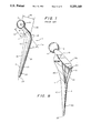
- FIG. 1 A typical prior art femoral component 2 is shown in FIG. 1.
- the component 2 is an integral metallic component having a head 4, a neck 6 and a stem 10 having a medial side 11 and a lateral side 13.
- the medial extension of the collar 7 is the platform 8.
- the stem 10 has a proximal end 19 and a distal end 20 which ends at the tip 22.
- the neck length 12 is measured from the center 18 of the head 4 to the base of the collar 7.
- the head-stem offset 14 is measured from the center 18 of the head 4 to the line 22 through the axis of the distal part 20 of the stem 10.
- the stem length 16 is measured from the medial base of the collar 7 to the tip 22 of the stem 10.
- the angle ⁇ of the neck 6 is measured by the angle at the intersection of the line 24 through the center 8 of the head 4 and the neck 6 with another line 26 along the lateral border of the distal half 20 of the stem 10.
- the femoral component may be made of any strong inert material. Materials which have been used in the past on such components include stainless steel, chromium cobalt molybdenum alloy (Co-Cr-Mo), titanium, or a combination such as Co-Cr-Mo with a ceramic head or titanium with a cobalt-chromium or ceramic head. It may also be made of isoelastic polyacetate.
- the head diameter is usually either 22, 26, 28, 32, or 38 mm with a neck length of 30-42 mm.
- the cross-section of the neck may be round, oval, or trapezoidal.
- the collar itself may or may not be present.
- the surface of the stem may be polished, dull, pre-coated with cement, press-fit, or have a porous-metal coating. There may or may not be fenestrations in the stem.
- the proximal third of the stem may be curved or angulated.
- the stem may be sabre-shaped, tapered, have a straight lateral edge or an anterior bow or a wide proximal third.
- the head-stem offset is generally 38-45 mm and the length is generally 12-18 cm or longer.
- the femoral component is made as a modular system with a tapered metal post on the stem to mate with a head component that makes for different neck lengths and diameter of heads made of cobalt-chrome or ceramic.
- a head component that makes for different neck lengths and diameter of heads made of cobalt-chrome or ceramic.
- a major problem from which most prior art femoral components suffer is stability of the component in place. Lack of complete stability can cause pain, failure of the artificial hip, fracture of the femur, or various other problems. Many attempts have been made to avoid such problems and add stability.
- One such attempt is the use of grouting medium or bone cement to fix the femoral component to the bone. In this case, bone is cleared from the medullary cavity to produce a larger space than required for the stem. Grouting material is inserted to fill the gap between the bone and the stem, as a means for fixing the device and as a means for load transfer between the device and the remaining bone.
- Efforts have been made to fix implants without the use of a grouting medium, in which case it is important that an accurate bone resection be performed.
- the femoral component must be selected to give the tightest fit possible to provide a mechanically stable support for physiological loading.
- the surface of the implant is treated to provide a porous or roughened structure which acts to promote bone tissue growth around the implant, further stabilizing the femoral component with respect to the bone.
- a major advantage of the latter system is the absence of cement or grouting medium, thus eliminating the long term inherent weakness and the short term toxic effects of these materials.
- the disadvantages are numerous.
- these stems have the added requirement of a sufficiently tight fit to prevent motion between metal and bone.
- Accurate bone resection customized to each type of available implant is difficult to achieve and often results in some initial looseness or lack of support.
- the implant will subsequently migrate to a more stable position, which may not be the ideal orientation for proper function of the femoral component.
- the requirement for a tight fit increases the possibility of fracture of the femur during insertion. Additionally, the patient must avoid bearing full weight on the hip for approximately six weeks to allow for bone formation.
- Treatment of the implant to form the porous or roughened surfaces may cause local stress sites in the implant which significantly increase the risk of fatigue fractures. Further, a considerable time is required for bone tissue ingrowth and stabilization of the implant to occur. This is a significant detriment to early patient rehabilitation. Additionally, surface treatment exposes a greater surface area of the implant, increasing diffusion of metal ions which are associated with an increased risk of toxic or pathological effects.
- the implant's stem may weaken from improper stress loads or decreased fatigue strength due to surface treatment. If this happens, the stem may bend or fracture, requiring its removal, which is particularly difficult if significant bone growth has occurred.
- FIG. 15 A diagram showing this conventional stress measurement system is shown in FIG. 15.
- the head 110 of the femoral component 112 to be tested is firmly clamped and inserted into a specimen holder 114 aligned in accordance with predetermined orientation angles.
- a fixing medium 116 is then poured into the holder 114 until it reaches a predetermined depth, usually about 50 mm below the collar of the stem.
- the specimen 112 is then left while the embedding medium 116 hardens.
- Epoxy resin is usually used as the embedding medium.
- the holder 114 with the fixed specimen 112 is then located in the testing machine and the entire stem may be immersed in a saline bath (not shown) in order to maintain physiological temperatures.
- the testing machine 119 then applies a load 118 vertically downward upon the head 110 of the femoral component of a predetermined amount and with a predetermined frequency. The vertical deflection is measured during the first minute of testing.
- a computer program controlling the load cycle is adjusted so that if the deflection exceeds 120% of the initial deflection, the testing machine will stop.
- Strain gauges 120 may be placed along the medial and lateral surfaces of the component stem 122 and the maximum bending stresses measured.
- Dobbs, H. S. "A Model Femur for In Vitro Testing of Femoral Components", J. Biomed. Eng., 3:225-34 (1981) discloses another model femur system for testing femoral components.
- This device uses a thin-walled tubular fixture of appropriate dimensions to simulate the femur. Strain gauges are placed on the stem as well as on the tubular structure. A three point bending test stand is disclosed in Reubin, J. D. et al., "Comparative Mechanical Properties of Forty-Five Total Hip Systems", Clin. Orthop., 141:55-65 (1979).
- Tanner K. E. et al., "A System for Modeling Forces on the Hip Joint in One-Legged Stance", J. Biomed. Eng., 10:289-90 (1988), the authors recognize that the previous systems for testing of hips or hip prostheses using a single unidirectional load do not make allowances for the loads applied via the greater or lesser trochanters. Accordingly, Tanner proposed an experimental arrangement which more closely models the forces on the hip joint in one-legged stance, taking into account the abductor muscles between the iliac crest and the greater trochanter. This test system is shown in FIG. 16. This model uses a 200 mm U channel 126 to model the pelvis with a movable plastic "acetabulum" 128.
- a proximal section of a femur 130 is implanted with an uncemented femoral component 132 and mounted vertically in a cylindrical holder 134, 150 mm from the line of action of the applied load.
- the abductors were modeled by a strip of stainless steel braid 136, screwed to the lateral aspect of the greater trochanter 140 using long cancellous bone screws 138.
- the braid 136 was then held at the end 142 of the U channel 126 at 20° to the vertical.
- the channel 126 remained approximately horizontal.
- the acetabular cup 128 was positioned to ensure that the femoral head 146 fitted into it with the "abductor tendon" 136 at the appropriate angle.
- the forces in the femur 130 and in the prosthesis 132 were supposed to be equivalent to those applied by standing on one leg so that the compressive force through the femoral head is reacted by a tensile force from the greater trochanter.
- the femoral component of the present invention is based on the discovery of the present inventor that the lateral aspects of the upper femur are under a compressive load, rather than a tensile stress as predicted by Koch.
- both the medial and lateral internal surfaces of the femur may be used as support surfaces for the femoral component.
- the femoral component of the present invention includes a lateral load-transferring support surface which is supported by the internal lateral surface of the upper femur when in use.
- the load transferring support surface is part of a wedge-shaped appendage on the lateral side of the proximal portion of the stem of the femoral component. This wedge-shaped appendage may be integral with the stem or may be formed separately and attached to a conventional femoral component by cement, screws, male/female socket fit or any other appropriate manner.
- the compressive load on the femoral component can be redistributed onto both sides of the femur to allow a safe and stable setting of the femoral component within the femur.
- FIG. 1 is a side view of a conventional prior art femoral component.
- FIG. 2 is a longitudinal cross-sectional view of a femur.
- FIG. 3 is a transverse cross-sectional view along lines 3--3 of FIG. 2.
- FIG. 4 is a transverse cross-sectional view along lines 4--4 of FIG. 2.
- FIG. 5 is a transverse cross-sectional view along lines 5--5 of FIG. 2.
- FIG. 6 is a transverse cross-sectional view along lines 6--6 of FIG. 2.
- FIG. 7 is a front elevational view of a cadaveric dissection mounted on a test stand for performing a static test of the lateral fascial band.
- FIG. 8 is a perspective view of one embodiment of a femoral component of the present invention.
- FIG. 9 is a side elevational view, partially broken away, of a femur with the femoral component of the present invention inserted in the medullary canal.
- FIG. 10 is a side elevational view of a femoral component with a conventional stem and a supporting lateral wedge attachable by a male/female joint.
- FIG. 11 is a side elevational view of the femoral component of FIG. 10 in assembled condition.
- FIG. 12 is a transverse cross-section of the assembled femoral component of FIG. 12 along line 12--12.
- FIG. 13 is a perspective view of a wedge usable in the embodiment of FIGS. 10 and 12.
- FIG. 14 is a side elevational view of a femoral component with a conventional stem and a supporting lateral wedge attachable using glue or cement.
- FIG. 15 is a front elevational view, partly in cross-section, of a conventional prior art stress measurement system.
- FIG. 16 is a front elevational view, partly in cross-section, of another prior art model femur system for testing femoral components.
- FIG. 17 is a front elevational view, partly in cross-section, of an apparatus for testing femoral component designs in accordance with the present invention.
- fascia lata/ilio-tibial band This soft tissue connects the greater trochanter of the femur to the lateral portion of the proximal tibia and essentially functions as a guy wire. It reduces the tensile strains in the proximal femur by acting as a lateral tension band. The result is a compressive load throughout the femur.
- Bone is not nature's optimal substance with which to resist tensile forces. Uncalcified collagen, i.e., tendon, has equal tensile strength to bone, with less weight. If the lateral aspect of the femur were under a purely tensile load, it would theoretically be composed of poorly calcified or uncalcified material, rather than relatively thick cortical bone. However, both radiological imaging and cadaveric dissections show relatively thick lateral cortical bone structure.
- the proximal half of a human femur 30 is shown in FIG. 2.
- the femur is comprised of the head 32, the neck 34, the greater trochanter 36, the lesser trochanter 38 and the medullary canal 40.
- the medial side 46 is the side of the femur 30 facing the midline of the body and the lateral side 48 is the side of the femur 30 toward the outside of the body.
- the cross-section of FIG. 3 is taken approximately 10 mm distal from the distal limit of the greater trochanter-forming wafer corresponding approximately to the level of the apophyseal scar 51, shown by line 50.
- the cross-sections of FIGS. 4, 5, and 6 are each approximately 5 mm distal to the previous cut.
- Cadaveric transsections of five human femora were made at the levels of lines 3--3, 4--4, 5--5 and 6--6 and the width of the medial and lateral cortical bone present was measured.
- the measured widths of the medial 44 and lateral 42 cortical bone at the cross-sections of FIGS. 3-6 are shown in Table I.
- cortical bone mass there is a significant amount of cortical bone mass in the lateral aspect 42 of the femur.
- This cortical bone mass begins with the inferior lateral aspect 52 of the greater trochanter 36 and coincides with the level of the apophyseal scar 51.
- the width of this cortical bone increases so that by 10 mm distal to the apophyseal scar, a point at approximately the level of the superior aspect of the lesser trochanter 38, it is more than 40% that of the medial cortex 44. With additional 5 mm increments, this lateral thickness increases to 50% and 73% of the medial cortical width, respectively.
- FIG. 7 A test was conducted of the static cadaveric loading of the human hemipelvis. The set-up for this test is shown in FIG. 7.
- a male cadaver was hemisected at L4 then sagittally sectioned through the pelvis 56.
- the leg was transected approximately 8 cm distal to the knee joint 57.
- the quadriceps femoris including rectus femoris and sartorius muscles, were removed.
- the abductor muscles 58, hamstrings, iliopsoas, tensor fascia lata 60, gluteus maximus and gluteus minimus were left intact as were the smaller rotators of the hip joint.
- the gluteus maxims was transected at its insertion on the greater trochanter and femur.
- the specimen was mounted vertically on static test stand 62, approximately at the anatomic position of the leg in its normal seven degrees of knee valgus standing position, as shown in FIG. 7.
- a steel hook 64 was affixed at L5, and another hook 66 was placed through the ileum, projecting laterally.
- a spring scale 68 was attached from the lateral pelvic hook 66 and anchored to another hook 70 which was secured to the tibia 71 approximately 4 cm below the knee joint 57, so as to parallel the lateral fascial band of the thigh (ITB).
- Serial weights 72 were attached by chain 73 to the pelvic hook 64 and the load registered on the lateral spring scale 68 was recorded.
- a tensile force of 0.7, 1.5 and 2.3 kg was observed in the spring scale. This resistance was sufficient to prevent varus displacement and to maintain the equilibrium state during pelvic loading.
- the ITB when loading at the body's theoretical center of gravity, the ITB maintained a medial-lateral equilibrium state across the hip joint by exerting a tensile resistance.
- the efficiency of this resistance required the ITB to experience a 1/3 kg of tensile load for each kg of downward load applied to the pelvis. It was noted that the gluteus maxims, having been sectioned, was not necessary for this equilibrium state to be maintained.
- the testing apparatus of the present invention takes into account the critical effects of the ITB. As shown in FIG. 17, the testing apparatus of the present invention is a substantial improvement over the model of Tanner et al. (FIG. 16), as it takes into account the ITB and the result is compression forces along the proximal lateral sides of the femur and the prosthesis. As seen in FIG. 17, a fixed cable 150 connects the load bar 152 with the fixed holder 154 at the distal end of the femur 156. The load 158 is applied to the bar 152 at a distance A from the center of the head 160 which is approximately twice the distance B from the center of the head to the point of attachment of the cable 150.
- this testing device approximates stresses which will occur in the natural environment, which will be a much more accurate test of the device than the prior art systems discussed above.
- the femoral component 162 being tested may simply be inserted uncemented into the reamed femur 156 with strain gauges 164 being placed at preselected points on the femoral component in order to measure the stresses which occur upon application of the load. Strain gauges 166 may also be placed on the femur 156 itself, if desired. It is not necessary that an actual femur 156 be used in this test device.
- the acetabulum cup 168 is preferably made of plastic at its inner contact surface which has a concavity designed to match the curve of the femoral component head 160 with which it is to come into contact.
- the acetabulum cup 168 is adjustably mounted on the load bar 152 by means of slidable bracket 170.
- the proximal end of cable 150 is adjustably mounted on the load bar 152 by means of a slidable bracket 172.
- the femur 156 in which it is implanted, or the synthetic equivalent thereof has a trochanteric portion 174 with which the cable 150 comes into contact.
- the angle from the contact point with the trochanter 174 to the connecting point 172 with the load bar 152 will usually be about 20° from the vertical, the same as that for the abductor muscle discussed with respect to FIG. 16.
- the distal end 176 of the cable 150 is either connected to the holder 154 or the frame 178 to which the holder 154 is connected so as to simulate the joining of the ITB to the lateral portion of the proximal tibia.
- the holder 154 is designed to hold the femur 156 by means of clamps 180 or any other suitable means, such as cement, in a predetermined alignment, which alignment preferably substantially corresponds to that of the standing femur.
- the purpose of the test stand is to simulate the forces to which the femoral component will be subjected when in use when subjected to a one-legged stance such as occurs in the course of walking.
- the femoral component being studied can be subjected to the conditions to which it will be subjected during use and the endurance properties of such a femoral component can be studied by means of the various strain gauges 164, 166.
- test stand of the present invention better simulates the actual forces to which the femur and the femoral component will be subjected when in use than any prior art test stand, it may be used to design and test all portions of the femoral component as well as various means of fixation of the femoral component to the femur.
- the hip endoprosthesis femoral component of the present invention was designed to take full advantage of the new knowledge that the proximal lateral cortex of the femur is under compressive load during unilateral stance.
- the component 76 is designed with a lateral load transferring support surface 78 which contacts and rests on the lateral femur when in place (see FIG. 9), thus preventing subsidence and rotation after emplacement and distributing the loading forces more naturally along the femur.
- the lateral support surface 78 is part of a wedge 80 fully integrated into the prosthesis 76.
- the femoral component 76 is otherwise conventionally comprised of a head 4, neck 6, and a stem 10 having a medial side 11, a lateral side 13, a proximal end 19, and a distal end 20. While no collar is present in the embodiment of FIG. 8, such may optionally be present.
- the lateral support surface 78 should be large enough in conjunction with the stem 10, to transfer all lateral loading forces onto the upper third of the femur 30.
- the stem 10 and wedge 80 should form a tight proximal fit in the medullary canal 40 when downward force is applied.
- the downward force applied to the head 4 of the endoprosthesis will be transferred through the neck 6, stem 10 and lateral support wedge 80.
- the force will be subsequently distributed onto the medial cortex 44 and lateral cortex 42 of the femur 30.
- the force will be entirely compression force and not tensile or pulling force.
- the lateral support surface 78 is not designed to penetrate or otherwise compromise the cancellous bone of the trochanter 36 either by a crushing or cutting action. Rather, the lateral support surface 78 is designed to rest against the lateral cortex 42 of the bone shaft.
- the lateral support wedge 80 is a fixed part of the endoprosthesis. It can be manufactured as one component, as in the embodiment of FIG. 8, or a retro-fit of a standard prosthesis as in the embodiments of FIGS. 10-14. The entire device 76 is inserted at one time.
- the lateral support wedge 84 is manufactured as a separate entity which can be emplaced on a conventional femoral component 2 such as that shown in FIG. 1.
- the support wedge 84 is maintained on the stem 10 by means of a male plug 86 disposed at the appropriate location on the proximal portion of the lateral stem 10 and a female socket 88 in the medial surface 87 of the wedge 84.
- the wedge 84 preferably includes side wings 90 which extend beyond the lateral surface 87 and are shaped to correspond in shape to the corresponding surface of the stem 10. This provides additional contact surface between the wedge 84 and the stem 10.
- the placement of the wedge 84 on the surface .89 of the stem 10 can be further enhanced by means of an adhesive such as glue or cement.
- Wedges 84 can be manufactured in various shapes and sizes so that the surgeon can select the appropriate combination of stem 10 and wedge 84 to make an appropriate prosthesis for the particular femur being fitted.
- wedge 91 is also manufactured as a separate component but without the female socket 88 as is used on the wedge 84 of FIGS. 10-13. Similarly, no male plug 86 need be disposed on stem 10.
- the lateral support wedge 91 is affixed to the surface 94 of the stem 10 solely by means of an appropriate adhesive, such as glue or cement.
- the medial surface 92 and the internal surfaces of the wings 96 of the wedge 91 are designed to match and attach to the lateral surface 94 of the stem 10.
- the lateral support surface 78 should have an anterior-posterior (A.P) width 82 which is large enough to provide sufficient support when contacting the internal surface of the lateral cortical bone, without acting as a stress riser which might violate or compromise the integrity of the bone.
- A.P width 82 of the support surface 78 should be at least 8 mm, preferably 10-20 mm, although it may be as wide as 30 mm.
- the width 82 may be substantially the same as the medial support surface of the stem 10 below the collar 7.
- the support surface 78 of the wedge 80 is preferably slightly rounded so as to approximate the radius of curvature of the internal geometry of the lateral surface of the medullary canal from about the level of the lesser trochanter to about the level of the apophyseal scar, such as is shown in the embodiments of FIGS. 9-14.
- Such a curvilinear surface gives better surface contact, thus permitting superior load transmission.
- additional anti-rotational or torsional support is obtained.
- the A-P width 82 is measured as a cross-section between the points 97 (see FIG. 12) on the surface of the wedge at which the tangent to the curve forms an angle of 45° with the horizontal.
- the medial-lateral (M-L) breadth 98 of the wedge 84 from the surface 92 to the lateral surface 78 at its broadest point (see FIG. 11) should be at least 10 mm, preferably 10-30 mm, most preferably 15-20 mm.
- the M.L breadth is measured in a corresponding manner, i.e., it extends what would otherwise have been the lateral surface of the stem by at least 10 mm. This breadth is optimal for the prevention of subsidence of the component when in use, over the course of time.
- the angle ⁇ between the support surface 28 and the midline 22 of the distal stem 20 is about 5°-20°, preferably about 10°-15°. Such an angle permits optimal transfer of the lateral loading forces onto the femur.
- flank The purpose of the flank is to project outwardly from both side faces of the stem and cut into the cortex of the anterior and posterior internal bone structure of the femur for improved proximal load transmission.
- the lateral surface of the proximal stem extends at an angle to the midline of the distal stem which may be within the range contemplated by the present invention.
- the present invention does not need a helical flank and such is to be expressly avoided in the present invention. Without such a helix, Kallabis et al would teach no reason to include a lateral surface with such an angle.
- the femoral endoprosthesis of U.S. Pat. No. 4,659,067 to Fournier shows a lateral surface which appears to have an angle of about 10°.
- the lateral surface comes to a point and does not include a load-bearing surface.
- this device is similar to the devices with thin anti-rotational fins (such as U.S. Pat. No. 4,936,863).
- Fournier requires oblique load-transfering projections on the anterior and posterior faces which are not included in the present invention.
- U.S. Pat. No. 4,778,475 to Ranawat et al discloses a femoral endoprosthesis with a wedge-shaped proximal portion in the intertrochanteric region which engages, for load transmission, the anterior and posterior endosteal surfaces of the femur, across the entire medial-lateral width thereof.
- the intention of Ranawat at is to transmit loads to the anterior and posterior femoral surfaces, which is contrary to the present invention which is designed to transmit loads to the medial and lateral femoral surfaces.
- the neck of Ranawat extends obliquely medially, anteriorly and superiorly from the proximal portion. This patent erroneously states that the bone is under tension at the proximal lateral aspect.
- the design is intended to minimize load transfer apart from the lateral distal tip and the region generally corresponding to the porous-coated recess shown in FIG. 7 of Ranawat. Because of the unusual oblique angle of the neck to the stem it is difficult to measure the angle of the proximal lateral surface to the midline of the distal stem. However, the present invention expressly avoids the use of a wedge shape of the anterior and posterior faces of the proximal stem at the medial and central portions thereof as well as the oblique angularity of the plane of the neck with the plane of the stem. Without these unusual features of Ranawat et al, there would be no reason to utilize a lateral surface with an angle of about 5°-20° with the midline of the distal stem.
- the femoral component of the present invention needs no structure specifically designed to transfer load to the anterior and posterior intertrochanteric region of the femur when in use.
- the bulge 99 of the wedge 84 shown particularly in FIGS. 12 and 13, may inherently cause some load transfer to the A.P surfaces of the femoral cortex and this is indeed advantageous as such contact prevents torsional forces.
- the design of the wedge 80 having the lateral support surface 78 when in place on the femoral component of the present invention has been discussed above with respect to particular angles and dimensions, those of ordinary skill in this art will understand that the specific angles and dimensions may vary depending on the size of the femur of the patient and other individual factors. However, the most important factor in the design with respect to the present invention is lateral supporting contact of the lateral support surface 78 of the wedge 80 on the internal surface of the lateral cortical bone from about the level of the lesser trochanter to about the level of the apophyseal scar.
- such contact should occur at least at the point of intersection of the midline of the stem with the lateral surface of the medullary canal, which lateral surface will normally be approximately perpendicular to said midline at that point. If the support surface 78 of the wedge 80 is in contact with the lateral surface of the medullary canal at that point, then this will ensure proper force distribution when the effect of the ITB is taken into account. As indicated above, the greater the width of the surface contact, the better the load transmission.
- any femoral component which is not designed and dimensioned such as to contact the lateral portion of the medullary canal at the point of intersection of the medullary canal with the line representing the midline of the stem of the femoral component will not fall within the scope of the preferred embodiment of the present invention.
- the femoral prosthesis of the present invention may optimally be designed intraoperatively in the manner described by Mulier, J. C. et al., Clin. Orthop., 249:97-112 (1989).
- a mold is made of the prepared femoral cavity which is accurately and thoroughly made using a laser.
- the femoral component is designed and manufactured while the operation is in progress using state-of-the-art computer and machining techniques.
- the femoral component may be designed and manufactured such that the lateral support surface of the wedge exactly matches the surface of the medullary canal opposite the stem of the component so as to have optimum surface contact for compressive force distribution.
- biocompatible materials other than metals may be used to make the femoral component, such as, for example, ultra-high molecular weight polyethylene, epoxy graphite, zirconia or alimunia ceramics, carbon fiber reinforced polyethylene-hydroxyapatite, etc. Some of these materials better lend themselves to the computer-aided manufacturing techniques of custom prostheses created intraoperatively as discussed above. All of these may readily be tested using the test stand of the present invention.
Abstract
Description
              TABLE I
______________________________________
             measured
measured     medial    measured   measured
medial       cortical  lateral    lateral
cortical     bone      cortical   cortical
bone (range) (mean)    bone (range)
                                  bone (mean)
______________________________________
FIG. 3
      5.5-7.0    6.2       0.5-1.0  0.9
FIG. 4
      5.0-7.5    6.0       2.0-3 0  2.5
FIG. 5
      5.2-7.0     6.14     2.5-4.5  3.3
FIG. 6
      4.0-7.5    6.0       3.5-5.0  4.4
______________________________________
Claims (1)
Priority Applications (15)
| Application Number | Priority Date | Filing Date | Title |
|---|---|---|---|
| US07/688,408 US5211666A (en) | 1991-04-22 | 1991-04-22 | Hip joint femoral component endoprosthesis with a lateral load-transferring support surface |
| AT92915862T ATE194066T1 (en) | 1991-04-22 | 1992-04-22 | FEMORAL ENDPROSTHESIS WITH SIDE SUPPORT SURFACE |
| DK92915862T DK0679075T3 (en) | 1991-04-22 | 1992-04-22 | Femoral endoprosthesis with lateral support surface |
| DE0679075T DE679075T1 (en) | 1991-04-22 | 1992-04-22 | FEMORAL ENDOPROTHESIS WITH LATERAL SUPPORT. |
| ES92915862T ES2150422T3 (en) | 1991-04-22 | 1992-04-22 | FEMORAL ENDOPROTESIS WITH SIDE SUPPORT SURFACE. |
| JP51188092A JP2917520B2 (en) | 1991-04-22 | 1992-04-22 | Femoral endoprosthesis with lateral support surface |
| EP92915862A EP0679075B1 (en) | 1991-04-22 | 1992-04-22 | Femoral endoprosthesis with a lateral support surface |
| PCT/US1992/003290 WO1992019186A1 (en) | 1991-04-22 | 1992-04-22 | Femoral endoprosthesis with a lateral support surface |
| DE69231207T DE69231207T2 (en) | 1991-04-22 | 1992-04-22 | FEMORAL ENDOPROTHESIS WITH LATERAL SUPPORT |
| AU23356/92A AU2335692A (en) | 1991-04-22 | 1992-04-22 | Femoral endoprosthesis with a lateral support surface |
| US07/950,546 US5259249A (en) | 1991-04-22 | 1992-09-25 | Hip joint femoral component endoprosthesis test device |
| JP50917894A JP3446145B2 (en) | 1992-09-25 | 1993-09-24 | Device for testing the durability of femoral components in hip prostheses |
| PCT/US1993/009065 WO1994008218A1 (en) | 1991-04-22 | 1993-09-24 | Apparatus for testing endurance properties of the femoral component of a hip prosthesis |
| AU51640/93A AU5164093A (en) | 1992-09-25 | 1993-09-24 | Apparatus for testing endurance properties of the femoral component of a hip prosthesis |
| GR20000402080T GR3034390T3 (en) | 1991-04-22 | 2000-09-13 | Femoral endoprosthesis with a lateral support surface. |
Applications Claiming Priority (2)
| Application Number | Priority Date | Filing Date | Title |
|---|---|---|---|
| US07/688,408 US5211666A (en) | 1991-04-22 | 1991-04-22 | Hip joint femoral component endoprosthesis with a lateral load-transferring support surface |
| US07/950,546 US5259249A (en) | 1991-04-22 | 1992-09-25 | Hip joint femoral component endoprosthesis test device |
Related Parent Applications (1)
| Application Number | Title | Priority Date | Filing Date |
|---|---|---|---|
| US07/688,408 Continuation-In-Part US5211666A (en) | 1991-04-22 | 1991-04-22 | Hip joint femoral component endoprosthesis with a lateral load-transferring support surface |
Publications (1)
| Publication Number | Publication Date |
|---|---|
| US5259249A true US5259249A (en) | 1993-11-09 |
Family
ID=27104218
Family Applications (2)
| Application Number | Title | Priority Date | Filing Date |
|---|---|---|---|
| US07/688,408 Expired - Lifetime US5211666A (en) | 1991-04-22 | 1991-04-22 | Hip joint femoral component endoprosthesis with a lateral load-transferring support surface |
| US07/950,546 Expired - Lifetime US5259249A (en) | 1991-04-22 | 1992-09-25 | Hip joint femoral component endoprosthesis test device |
Family Applications Before (1)
| Application Number | Title | Priority Date | Filing Date |
|---|---|---|---|
| US07/688,408 Expired - Lifetime US5211666A (en) | 1991-04-22 | 1991-04-22 | Hip joint femoral component endoprosthesis with a lateral load-transferring support surface |
Country Status (10)
| Country | Link |
|---|---|
| US (2) | US5211666A (en) |
| EP (1) | EP0679075B1 (en) |
| JP (1) | JP2917520B2 (en) |
| AT (1) | ATE194066T1 (en) |
| AU (1) | AU2335692A (en) |
| DE (2) | DE69231207T2 (en) |
| DK (1) | DK0679075T3 (en) |
| ES (1) | ES2150422T3 (en) |
| GR (1) | GR3034390T3 (en) |
| WO (2) | WO1992019186A1 (en) |
Cited By (28)
| Publication number | Priority date | Publication date | Assignee | Title |
|---|---|---|---|---|
| US6228121B1 (en) | 1999-06-21 | 2001-05-08 | Depuy Othopedics, Inc. | Prosthesis system and method of implanting |
| US20020117749A1 (en) * | 1996-09-19 | 2002-08-29 | Farnworth Warren M. | Heat transfer material for an improved die edge contacting socket |
| US20040177701A1 (en) * | 2003-03-10 | 2004-09-16 | Rafail Zubok | Joint simulator testing machine |
| US20040226343A1 (en) * | 2003-02-20 | 2004-11-18 | Saphirwerk Industrieprodukte Ag | Test device for femoral head prosthesis |
| US20050241404A1 (en) * | 2004-05-03 | 2005-11-03 | Salvesen William R | Method and apparatus for testing a joint replacement device |
| US20070169562A1 (en) * | 2006-01-13 | 2007-07-26 | Mts Systems Corporation | Orthopedic simulator with integral load actuators |
| US20070169566A1 (en) * | 2006-01-13 | 2007-07-26 | Mts Systems Corporation | Integrated central manifold for orthopedic simulator |
| US20070172394A1 (en) * | 2006-01-20 | 2007-07-26 | Schulz Bradley D | Specimen containment module for orthopedic simulator |
| US20070169561A1 (en) * | 2006-01-13 | 2007-07-26 | Mts Systems Corporation | Mechanism arrangement for orthopedic simulator |
| US20070169573A1 (en) * | 2006-01-13 | 2007-07-26 | Mts Systems Corporation | Orthopedic simulator with fluid concentration maintenance arrangement for controlling fluid concentration of specimen baths |
| US20070260373A1 (en) * | 2006-05-08 | 2007-11-08 | Langer William J | Dynamic vehicle durability testing and simulation |
| US20070275355A1 (en) * | 2006-05-08 | 2007-11-29 | Langer William J | Integration and supervision for modeled and mechanical vehicle testing and simulation |
| US7383738B2 (en) | 2003-12-05 | 2008-06-10 | Mts Systems Corporation | Method to extend testing through integration of measured responses virtual models |
| US20080275682A1 (en) * | 2007-05-04 | 2008-11-06 | Langer William J | Method and system for axle evaluation and tuning with loading system and vehicle model |
| US20080275681A1 (en) * | 2007-05-04 | 2008-11-06 | Langer William J | Method and system for vehicle damper system evaluation and tuning with loading system and vehicle model |
| US20080271542A1 (en) * | 2003-12-05 | 2008-11-06 | Mts Systems Corporation | Method to extend testing through integration of measured responses with virtual models |
| US20090012763A1 (en) * | 2007-05-04 | 2009-01-08 | Mts Systems Corporation | Method and system for tire evaluation and tuning with loading system and vehicle model |
| US20100088058A1 (en) * | 2008-10-02 | 2010-04-08 | Mts Systems Corporation | Methods and systems for off-line control for simulation of coupled hybrid dynamic systems |
| US7770446B2 (en) | 2006-01-13 | 2010-08-10 | Mts Systems Corporation | Orthopedic simulator with temperature controller arrangement for controlling temperature of specimen baths |
| US7913573B2 (en) | 2006-01-13 | 2011-03-29 | Mts Systems Corporation | Orthopedic simulator with a multi-axis slide table assembly |
| US8029573B2 (en) | 2006-12-07 | 2011-10-04 | Ihip Surgical, Llc | Method and apparatus for total hip replacement |
| US8579985B2 (en) | 2006-12-07 | 2013-11-12 | Ihip Surgical, Llc | Method and apparatus for hip replacement |
| US8974540B2 (en) | 2006-12-07 | 2015-03-10 | Ihip Surgical, Llc | Method and apparatus for attachment in a modular hip replacement or fracture fixation device |
| DE102015102588A1 (en) * | 2015-02-24 | 2016-08-25 | Waldemar Link Gmbh & Co. Kg | Alignment device for aligning femoral hip stem implant components for testing purposes |
| US9477793B2 (en) | 2008-10-02 | 2016-10-25 | Mts Systems Corporation | Method and systems for off-line control for simulation of coupled hybrid dynamic systems |
| US10061278B2 (en) | 2013-09-09 | 2018-08-28 | Mts Systems Corporation | Method of off-line hybrid system assessment for test monitoring and modification |
| US10371601B2 (en) | 2013-09-09 | 2019-08-06 | Mts Systems Corporation | Methods and systems for testing coupled hybrid dynamic systems |
| CN111650040A (en) * | 2020-06-09 | 2020-09-11 | 哈尔滨工业大学 | Multi-degree-of-freedom femur static and fatigue test fixture |
Families Citing this family (34)
| Publication number | Priority date | Publication date | Assignee | Title |
|---|---|---|---|---|
| EP0547354A1 (en) * | 1991-12-17 | 1993-06-23 | Dr.Ing.h.c. F. Porsche Aktiengesellschaft | Adjustable hip joint endoprothesis |
| CA2154268A1 (en) * | 1993-02-09 | 1994-08-18 | Thomas F. Mccarthy | Modular hip prosthesis |
| FR2703583B1 (en) * | 1993-04-07 | 1995-06-09 | Medinov Sa | FEMALE IMPLANT FOR HIP PROSTHESIS. |
| US5593451A (en) * | 1994-06-01 | 1997-01-14 | Implex Corp. | Prosthetic device and method of implantation |
| FR2732891B1 (en) * | 1995-04-12 | 1997-10-24 | Setiey Louis | FEMALE RECONSTRUCTION AND ANCILLARY PROSTHESIS FOR ITS INSTALLATION |
| US5766262A (en) * | 1996-03-29 | 1998-06-16 | Mikhail; W. E. Michael | Femoral prosthesis with spacer |
| US5776204A (en) * | 1996-05-24 | 1998-07-07 | Howmedica Inc. | Asymmetric hip stem |
| DE29612857U1 (en) * | 1996-07-24 | 1997-11-20 | Link Waldemar Gmbh Co | Endoprosthesis |
| US7255712B1 (en) | 1997-04-15 | 2007-08-14 | Active Implants Corporation | Bone growth promoting implant |
| US6395004B1 (en) * | 1997-11-14 | 2002-05-28 | Sulzer Orthopedics Inc. | Orthopedic trial prosthesis and saw guide instrument |
| EP1013244A1 (en) * | 1998-12-21 | 2000-06-28 | Benoist Girard Et Cie | Prosthetic femoral component |
| US8920509B2 (en) | 2000-04-10 | 2014-12-30 | Biomet Manufacturing, Llc | Modular radial head prosthesis |
| US8114163B2 (en) | 2000-04-10 | 2012-02-14 | Biomet Manufacturing Corp. | Method and apparatus for adjusting height and angle for a radial head |
| US8535382B2 (en) | 2000-04-10 | 2013-09-17 | Biomet Manufacturing, Llc | Modular radial head prostheses |
| FR2826864B1 (en) * | 2001-07-04 | 2003-10-10 | Groupe Lepine | METHOD FOR DIMENSIONING A HIP JOINT PROSTHESIS AND PROSTHESIS THUS OBTAINED |
| US7572295B2 (en) | 2001-12-04 | 2009-08-11 | Active Implants Corporation | Cushion bearing implants for load bearing applications |
| ATE431113T1 (en) * | 2002-05-23 | 2009-05-15 | Active Implants Corp | JOINT AND DENTAL IMPLANTS |
| US20040158329A1 (en) * | 2003-02-10 | 2004-08-12 | Waldemar Link (Gmbh & Co.) | Hip joint prosthesis with shaft inserted into femur |
| GB0305449D0 (en) * | 2003-03-10 | 2003-04-16 | Benoist Girard Sas | Femoral prosthesis |
| EP1623685A1 (en) * | 2004-08-06 | 2006-02-08 | WALDEMAR LINK GmbH & Co. KG | Hip prosthesis with stem for implantation into the femur |
| AU2006201835B2 (en) * | 2005-05-09 | 2012-08-30 | Smith & Nephew, Inc. | Orthopaedic implants and methods for making the same |
| US8187280B2 (en) | 2007-10-10 | 2012-05-29 | Biomet Manufacturing Corp. | Knee joint prosthesis system and method for implantation |
| US8328873B2 (en) | 2007-01-10 | 2012-12-11 | Biomet Manufacturing Corp. | Knee joint prosthesis system and method for implantation |
| US8163028B2 (en) | 2007-01-10 | 2012-04-24 | Biomet Manufacturing Corp. | Knee joint prosthesis system and method for implantation |
| US8562616B2 (en) | 2007-10-10 | 2013-10-22 | Biomet Manufacturing, Llc | Knee joint prosthesis system and method for implantation |
| US8157869B2 (en) | 2007-01-10 | 2012-04-17 | Biomet Manufacturing Corp. | Knee joint prosthesis system and method for implantation |
| JP5634501B2 (en) * | 2009-05-05 | 2014-12-03 | シンセス ゲゼルシャフト ミット ベシュレンクテル ハフツングSynthes Gmbh | Nail locking system |
| US8679130B2 (en) | 2010-03-05 | 2014-03-25 | Biomet Manufacturing, Llc | Guide assembly for lateral implants and associated methods |
| US8333807B2 (en) * | 2010-03-05 | 2012-12-18 | Biomet Manufacturing Corp. | Method and apparatus for trialing and implanting a modular femoral hip |
| US8419743B2 (en) * | 2010-03-05 | 2013-04-16 | Biomet Manufacturing Corp. | Assembly tool for modular implants and associated method |
| US8221432B2 (en) | 2010-03-05 | 2012-07-17 | Biomet Manufacturing Corp. | Method and apparatus for implanting a modular femoral hip |
| US8460393B2 (en) | 2010-03-05 | 2013-06-11 | Biomet Manufacturing Corp. | Modular lateral hip augments |
| US8529569B2 (en) * | 2010-03-05 | 2013-09-10 | Biomet Manufacturing, Llc | Method and apparatus for preparing a proximal femur |
| CN111650041B (en) * | 2020-06-09 | 2021-07-13 | 哈尔滨工业大学 | Femur static compression and compression-compression fatigue test method |
Family Cites Families (51)
| Publication number | Priority date | Publication date | Assignee | Title |
|---|---|---|---|---|
| US3896505A (en) * | 1970-03-31 | 1975-07-29 | Franz Donatus Timmermans | Endoprosthesis for the hipjoint |
| SU440014A1 (en) * | 1972-05-04 | 1978-08-05 | Саратовский государственный медицинский институт | Endoprosthesis of proximal end of thighbone |
| CH568753A5 (en) * | 1973-08-31 | 1975-11-14 | Oscobal Ag | |
| US3863273A (en) * | 1973-09-20 | 1975-02-04 | Meditec Inc | Orthopedic prosthetic implant devices |
| SU545343A1 (en) * | 1974-10-31 | 1977-02-05 | Саратовский Государственный Научно-Исследовательский Институт Травматологии И Ортопедии | Method for producing bone endoprosthesis model |
| GB1511859A (en) * | 1974-12-24 | 1978-05-24 | Friedrichsfeld Gmbh | Hip-joint endoprostheses |
| DE2834155C3 (en) * | 1978-08-04 | 1981-09-17 | Friedrichsfeld Gmbh, Steinzeug- Und Kunststoffwerke, 6800 Mannheim | Femoral shaft for a hip joint endoprosthesis |
| FR2438469A1 (en) * | 1978-10-11 | 1980-05-09 | Tornier Sa Ets | HIP PROSTHESIS WITH ELASTIC FEMALE ROD |
| CH642252A5 (en) * | 1980-01-14 | 1984-04-13 | Sulzer Ag | LEAFY SHAFT FOR ANCHORING A HIP JOINT PROSTHESIS. |
| CH647942A5 (en) * | 1980-11-25 | 1985-02-28 | Sulzer Ag | FEMUR HEAD PROSTHESIS. |
| US4549319A (en) * | 1982-08-03 | 1985-10-29 | United States Medical Corporation | Artificial joint fixation to bone |
| DE3216539C3 (en) * | 1982-05-03 | 1997-09-25 | Link Waldemar Gmbh Co | Thigh part of a hip joint endoprosthesis |
| DE3216538A1 (en) * | 1982-05-03 | 1983-11-03 | Waldemar Link (Gmbh & Co), 2000 Hamburg | BONE IMPLANT, IN PARTICULAR FEMORAL HIP JOINT PROSTHESIS |
| US4530114A (en) * | 1982-07-16 | 1985-07-23 | Slobodan Tepic | Total hip joint prostheses |
| CH659580A5 (en) * | 1983-06-07 | 1987-02-13 | Sulzer Ag | THE BIG TROCHANT REPLACING IMPLANT. |
| GB8401059D0 (en) * | 1984-01-16 | 1984-02-15 | Exeter University Of | Fixation of implants in bone |
| US4846839A (en) * | 1984-02-09 | 1989-07-11 | Joint Medical Products Corporation | Apparatus for affixing a prosthesis to bone |
| CH662268A5 (en) * | 1984-03-06 | 1987-09-30 | Protek Ag | Hip joint prosthesis. |
| EP0159510B1 (en) * | 1984-04-14 | 1990-05-30 | HOWMEDICA INTERNATIONAL, INC. Zweigniederlassung Kiel | Hip joint endoprosthesis |
| WO1985005027A1 (en) * | 1984-05-08 | 1985-11-21 | Fried. Krupp Gesellschaft Mit Beschränkter Haftung | Artificial joint system and process for its implantation |
| FR2569978B1 (en) * | 1984-09-10 | 1989-02-24 | Fournier Jacques Andre | IMPLANT FOR COXO-FEMORAL PROSTHESIS |
| CS245125B1 (en) * | 1984-11-09 | 1986-08-14 | Miroslav Petrtyl | Adaptable isoelastic hip endoprosthesis |
| FR2579453B1 (en) * | 1985-03-27 | 1991-06-28 | Epinette Jean Alain | FEMALE HIP PROSTHESIS COMPONENT, NOT CEMENTED |
| CH666178A5 (en) * | 1985-06-12 | 1988-07-15 | Sulzer Ag | FEMUR HEAD PROSTHESIS. |
| CA1290099C (en) * | 1986-01-21 | 1991-10-08 | Thomas H. Mallory | Porous-coated artificial joints |
| DE3625520A1 (en) * | 1986-03-15 | 1987-09-17 | Mecron Med Prod Gmbh | BONE IMPLANT |
| CH669107A5 (en) * | 1986-04-03 | 1989-02-28 | Sulzer Ag | LEAF-LIKE SHAFT FOR ANCHORAGE OF A HIP PROSTHESIS IN THE FEMUR. |
| CH669106A5 (en) * | 1986-04-03 | 1989-02-28 | Sulzer Ag | LEAF-LIKE SHAFT FOR ANCHORAGE OF A HIP PROSTHESIS IN THE FEMUR. |
| US4778475A (en) * | 1986-04-15 | 1988-10-18 | New York Society For The Relief Of The Ruptured And Crippled | Femoral prosthesis for total hip replacement |
| US4790852A (en) * | 1986-09-15 | 1988-12-13 | Joint Medical Products Corporation | Sleeves for affixing artificial joints to bone |
| DE3775707D1 (en) * | 1986-10-25 | 1992-02-13 | Paulo Gallinaro | Hip joint prosthesis. |
| US4728335A (en) * | 1986-12-15 | 1988-03-01 | Jurgutis John A | Hip prosthesis |
| DE3725387A1 (en) * | 1987-01-03 | 1989-02-09 | Kallabis Manfred | A hip joint prosthesis |
| US4881536A (en) * | 1987-01-22 | 1989-11-21 | Noble Phillip C | Method and apparatus for prosthesis placement |
| CH673217A5 (en) * | 1987-06-23 | 1990-02-28 | Sulzer Ag | |
| US5018285A (en) * | 1987-08-24 | 1991-05-28 | Zimmer, Inc. | Method of constructing prosthetic implant with wrapped porous surface |
| DE8712578U1 (en) * | 1987-09-17 | 1987-12-17 | Howmedica Gmbh, 2314 Schoenkirchen, De | |
| NL8702626A (en) * | 1987-11-03 | 1989-06-01 | Orthopaedic Tech Bv | METHOD FOR FORMING A GEOMETRY OF AN ENDOPROTHESIS, A FEMUR HEAD PROSTHESIS, AN ACETABULUM PROSTHESIS, A METHOD FOR BOTTING A FEMUR HEAD PROSTHESIS AND AN INSTRUMENT FOR PLACING ACROTHESES |
| US4919670A (en) * | 1988-02-03 | 1990-04-24 | Intermedics Orthopedics, Inc. | Modular humeral prosthesis |
| DE3804239A1 (en) * | 1988-02-11 | 1989-08-24 | Karl Heinrich Prof Dr Taeger | JOINT PART FOR A JOINT PROSTHESIS |
| GB8809856D0 (en) * | 1988-04-26 | 1988-06-02 | Headcorn Instrumentation Ltd | Hip prosthesis |
| CA1304889C (en) * | 1988-05-12 | 1992-07-14 | Peter John Brooks | Femoral insert |
| US4936863A (en) * | 1988-05-13 | 1990-06-26 | Hofmann Aaron A | Hip prosthesis |
| CH675826A5 (en) * | 1988-08-24 | 1990-11-15 | Sulzer Ag | |
| JPH0292352A (en) * | 1988-09-29 | 1990-04-03 | Aisin Seiki Co Ltd | Artificial condyle for hip joint |
| CH676664A5 (en) * | 1989-01-10 | 1991-02-28 | Sulzer Ag | |
| EP0385585A1 (en) * | 1989-02-06 | 1990-09-05 | Stephen M. Horowitz, M.D. | A hip prosthesis and method for implanting the same |
| US4983183A (en) * | 1989-02-06 | 1991-01-08 | Horowitz Stephen M | Hip prosthesis and method for implanting the same |
| CH680110A5 (en) * | 1989-11-16 | 1992-06-30 | Sulzer Ag | |
| EP0447734B1 (en) * | 1990-03-13 | 1993-10-06 | SULZER Medizinaltechnik AG | Femoral head prosthesis for cementless affixation |
| US5002578A (en) * | 1990-05-04 | 1991-03-26 | Venus Corporation | Modular hip stem prosthesis apparatus and method |
-
1991
- 1991-04-22 US US07/688,408 patent/US5211666A/en not_active Expired - Lifetime
-
1992
- 1992-04-22 DE DE69231207T patent/DE69231207T2/en not_active Expired - Lifetime
- 1992-04-22 ES ES92915862T patent/ES2150422T3/en not_active Expired - Lifetime
- 1992-04-22 EP EP92915862A patent/EP0679075B1/en not_active Expired - Lifetime
- 1992-04-22 WO PCT/US1992/003290 patent/WO1992019186A1/en active IP Right Grant
- 1992-04-22 JP JP51188092A patent/JP2917520B2/en not_active Expired - Fee Related
- 1992-04-22 AT AT92915862T patent/ATE194066T1/en not_active IP Right Cessation
- 1992-04-22 DE DE0679075T patent/DE679075T1/en active Pending
- 1992-04-22 DK DK92915862T patent/DK0679075T3/en active
- 1992-04-22 AU AU23356/92A patent/AU2335692A/en not_active Abandoned
- 1992-09-25 US US07/950,546 patent/US5259249A/en not_active Expired - Lifetime
-
1993
- 1993-09-24 WO PCT/US1993/009065 patent/WO1994008218A1/en active Application Filing
-
2000
- 2000-09-13 GR GR20000402080T patent/GR3034390T3/en not_active IP Right Cessation
Non-Patent Citations (2)
| Title |
|---|
| Smith, H. W. et al. An Osteoclast for Whole Bone Testing. 8th Annual Northeast Bioengineering Conference. Cambridge, MA, USA, (Mar. 27 28, 1980) pp. 1 4. * |
| Smith, H. W. et al. An Osteoclast for Whole Bone Testing. 8th Annual Northeast Bioengineering Conference. Cambridge, MA, USA, (Mar. 27-28, 1980) pp. 1-4. |
Cited By (52)
| Publication number | Priority date | Publication date | Assignee | Title |
|---|---|---|---|---|
| US20020117749A1 (en) * | 1996-09-19 | 2002-08-29 | Farnworth Warren M. | Heat transfer material for an improved die edge contacting socket |
| US6228121B1 (en) | 1999-06-21 | 2001-05-08 | Depuy Othopedics, Inc. | Prosthesis system and method of implanting |
| US6901811B2 (en) * | 2003-02-20 | 2005-06-07 | Saphirwerk Industrieprodukte Ag | Test device for femoral head prosthesis |
| US20040226343A1 (en) * | 2003-02-20 | 2004-11-18 | Saphirwerk Industrieprodukte Ag | Test device for femoral head prosthesis |
| US7040177B2 (en) | 2003-03-10 | 2006-05-09 | Spinecore, Inc. | Joint simulator testing machine |
| US7284446B2 (en) | 2003-03-10 | 2007-10-23 | Spinecore, Inc. | Joint simulator testing machine |
| US6865954B2 (en) | 2003-03-10 | 2005-03-15 | Spinecore, Inc. | Joint simulator testing machine |
| US7603911B2 (en) | 2003-03-10 | 2009-10-20 | Spinecore, Inc. | Joint simulator testing machine |
| US20060117864A1 (en) * | 2003-03-10 | 2006-06-08 | Spinecore, Inc. | Joint simulator testing machine |
| US7131338B2 (en) | 2003-03-10 | 2006-11-07 | Spinecore, Inc. | Joint simulator testing machine |
| US20060272424A1 (en) * | 2003-03-10 | 2006-12-07 | Spinecore, Inc. | Joint simulator testing machine |
| US20050056099A1 (en) * | 2003-03-10 | 2005-03-17 | Spinecore, Inc. | Joint simulator testing machine |
| US20040177701A1 (en) * | 2003-03-10 | 2004-09-16 | Rafail Zubok | Joint simulator testing machine |
| US20080202252A1 (en) * | 2003-03-10 | 2008-08-28 | Spinecore, Inc. | Joint simulator testing machine |
| US7357038B2 (en) | 2003-03-10 | 2008-04-15 | Spinecore, Inc. | Joint simulator testing machine |
| US20080271542A1 (en) * | 2003-12-05 | 2008-11-06 | Mts Systems Corporation | Method to extend testing through integration of measured responses with virtual models |
| US7383738B2 (en) | 2003-12-05 | 2008-06-10 | Mts Systems Corporation | Method to extend testing through integration of measured responses virtual models |
| US7219555B2 (en) * | 2004-05-03 | 2007-05-22 | Salvesen William R | Method and apparatus for testing a joint replacement device |
| US20050241404A1 (en) * | 2004-05-03 | 2005-11-03 | Salvesen William R | Method and apparatus for testing a joint replacement device |
| US20070169562A1 (en) * | 2006-01-13 | 2007-07-26 | Mts Systems Corporation | Orthopedic simulator with integral load actuators |
| US7779708B2 (en) | 2006-01-13 | 2010-08-24 | Mts Systems Corporation | Orthopedic simulator with fluid concentration maintenance arrangement for controlling fluid concentration of specimen baths |
| US20070169561A1 (en) * | 2006-01-13 | 2007-07-26 | Mts Systems Corporation | Mechanism arrangement for orthopedic simulator |
| US7770446B2 (en) | 2006-01-13 | 2010-08-10 | Mts Systems Corporation | Orthopedic simulator with temperature controller arrangement for controlling temperature of specimen baths |
| US20070169566A1 (en) * | 2006-01-13 | 2007-07-26 | Mts Systems Corporation | Integrated central manifold for orthopedic simulator |
| US20070169573A1 (en) * | 2006-01-13 | 2007-07-26 | Mts Systems Corporation | Orthopedic simulator with fluid concentration maintenance arrangement for controlling fluid concentration of specimen baths |
| US8156824B2 (en) | 2006-01-13 | 2012-04-17 | Mts Systems Corporation | Mechanism arrangement for orthopedic simulator |
| US7762147B2 (en) | 2006-01-13 | 2010-07-27 | Mts Systems Corporation | Orthopedic simulator with integral load actuators |
| US7913573B2 (en) | 2006-01-13 | 2011-03-29 | Mts Systems Corporation | Orthopedic simulator with a multi-axis slide table assembly |
| US7824184B2 (en) | 2006-01-13 | 2010-11-02 | Mts Systems Corporation | Integrated central manifold for orthopedic simulator |
| US7654150B2 (en) | 2006-01-20 | 2010-02-02 | Mts Systems Corporation | Specimen containment module for orthopedic simulator |
| US20070172394A1 (en) * | 2006-01-20 | 2007-07-26 | Schulz Bradley D | Specimen containment module for orthopedic simulator |
| US20070260373A1 (en) * | 2006-05-08 | 2007-11-08 | Langer William J | Dynamic vehicle durability testing and simulation |
| US20070275355A1 (en) * | 2006-05-08 | 2007-11-29 | Langer William J | Integration and supervision for modeled and mechanical vehicle testing and simulation |
| US8211183B2 (en) | 2006-12-07 | 2012-07-03 | Ihip Surgical, Llc | Methods and systems for total hip replacement |
| US8579985B2 (en) | 2006-12-07 | 2013-11-12 | Ihip Surgical, Llc | Method and apparatus for hip replacement |
| US9237949B2 (en) | 2006-12-07 | 2016-01-19 | Ihip Surgical, Llc | Method and apparatus for hip replacement |
| US8029573B2 (en) | 2006-12-07 | 2011-10-04 | Ihip Surgical, Llc | Method and apparatus for total hip replacement |
| US8974540B2 (en) | 2006-12-07 | 2015-03-10 | Ihip Surgical, Llc | Method and apparatus for attachment in a modular hip replacement or fracture fixation device |
| US8795381B2 (en) | 2006-12-07 | 2014-08-05 | Ihip Surgical, Llc | Methods and systems for hip replacement |
| US20080275681A1 (en) * | 2007-05-04 | 2008-11-06 | Langer William J | Method and system for vehicle damper system evaluation and tuning with loading system and vehicle model |
| US20080275682A1 (en) * | 2007-05-04 | 2008-11-06 | Langer William J | Method and system for axle evaluation and tuning with loading system and vehicle model |
| US20090012763A1 (en) * | 2007-05-04 | 2009-01-08 | Mts Systems Corporation | Method and system for tire evaluation and tuning with loading system and vehicle model |
| US20100088058A1 (en) * | 2008-10-02 | 2010-04-08 | Mts Systems Corporation | Methods and systems for off-line control for simulation of coupled hybrid dynamic systems |
| US8135556B2 (en) | 2008-10-02 | 2012-03-13 | Mts Systems Corporation | Methods and systems for off-line control for simulation of coupled hybrid dynamic systems |
| US9477793B2 (en) | 2008-10-02 | 2016-10-25 | Mts Systems Corporation | Method and systems for off-line control for simulation of coupled hybrid dynamic systems |
| US10339265B2 (en) | 2008-10-02 | 2019-07-02 | Mts Systems Corporation | Method and systems for off-line control for simulation of coupled hybrid dynamic systems |
| US10061278B2 (en) | 2013-09-09 | 2018-08-28 | Mts Systems Corporation | Method of off-line hybrid system assessment for test monitoring and modification |
| US10371601B2 (en) | 2013-09-09 | 2019-08-06 | Mts Systems Corporation | Methods and systems for testing coupled hybrid dynamic systems |
| US10876930B2 (en) | 2013-09-09 | 2020-12-29 | Mts Systems Corporation | Methods and systems for testing coupled hybrid dynamic systems |
| DE102015102588A1 (en) * | 2015-02-24 | 2016-08-25 | Waldemar Link Gmbh & Co. Kg | Alignment device for aligning femoral hip stem implant components for testing purposes |
| DE102015102588B4 (en) | 2015-02-24 | 2017-02-23 | Waldemar Link Gmbh & Co. Kg | Alignment device for aligning femoral hip stem implant components for testing purposes |
| CN111650040A (en) * | 2020-06-09 | 2020-09-11 | 哈尔滨工业大学 | Multi-degree-of-freedom femur static and fatigue test fixture |
Also Published As
| Publication number | Publication date |
|---|---|
| AU2335692A (en) | 1992-12-21 |
| DK0679075T3 (en) | 2000-11-13 |
| DE69231207T2 (en) | 2002-11-07 |
| ATE194066T1 (en) | 2000-07-15 |
| ES2150422T3 (en) | 2000-12-01 |
| DE679075T1 (en) | 1997-06-26 |
| EP0679075A1 (en) | 1995-11-02 |
| GR3034390T3 (en) | 2000-12-29 |
| WO1992019186A1 (en) | 1992-11-12 |
| JP2917520B2 (en) | 1999-07-12 |
| WO1994008218A1 (en) | 1994-04-14 |
| EP0679075A4 (en) | 1994-07-06 |
| US5211666A (en) | 1993-05-18 |
| JPH06506858A (en) | 1994-08-04 |
| EP0679075B1 (en) | 2000-06-28 |
| DE69231207D1 (en) | 2000-08-03 |
Similar Documents
| Publication | Publication Date | Title |
|---|---|---|
| US5259249A (en) | Hip joint femoral component endoprosthesis test device | |
| Kim et al. | Strain distribution in the proximal human femur: an in vitro comparison in the intact femur and after insertion of reference and experimental femoral stems | |
| US5318571A (en) | Method and apparatus for simplifying total hip arthroplasty | |
| Burke et al. | Micromotion of cemented and uncemented femoral components | |
| STULBERG et al. | The rationale, design characteristics, and preliminary results of a primary custom total hip prosthesis | |
| Decking et al. | Changes in strain distribution of loaded proximal femora caused by different types of cementless femoral stems | |
| Jacob et al. | An investigation into biomechanical causes of prosthesis stem loosening within the proximal end of the human femur | |
| HARRIS et al. | Intraoperative measurement of rotational stability of femoral components of total hip arthroplasty. | |
| Lachiewicz et al. | In vitro initial fixation of porous-coated acetabular total hip components: a biomechanical comparative study | |
| Phillips et al. | Loosening of cementless femoral stems: a biomechanical analysis of immediate fixation with loading vertical, femur horizontal | |
| EP1848377A2 (en) | Apparatus and method for shoulder arthroplasty | |
| Rohlmann et al. | Effects of stem design and material properties on stresses in hip endoprostheses | |
| Otani et al. | Effects of femoral component material properties on cementless fixation in total hip arthroplasty: A comparison study between carbon composite, titanium alloy, and stainless steel | |
| Finlay et al. | In vitro analysis of proximal femoral strains using PCA femoral implants and a hip-abductor muscle simulator | |
| Lionberger et al. | Effects of prosthetic acetabular replacement on strains in the pelvis | |
| Yildirim et al. | Comparative fixation and subsidence profiles of cementless unicompartmental knee arthroplasty implants | |
| Jacob | Biomechanical principles and design details of the thrust plate prosthesis | |
| Monti et al. | In vitro testing of the primary stability of the VerSys enhanced taper stem: a comparative study in intact and intraoperatively cracked femora | |
| Sangiorgio et al. | Fixation of non-cemented total hip arthroplasty femoral components in a simulated proximal bone defect model | |
| Page et al. | Alterations in femoral and acetabular bone strains immediately following cementless total hip arthroplasty: an in vitro canine study | |
| Clements et al. | Determination of pelvic ring stability: a new technique using a composite hemi-pelvis | |
| JP3446145B2 (en) | Device for testing the durability of femoral components in hip prostheses | |
| Lee et al. | Effects of screw types in cementless fixation of tibial tray implants: stability and strength assessment | |
| Breusch et al. | In-vitro rotational stability of cemented stem designs | |
| Willems et al. | The stability of the femoral component of a minimal invasive total hip replacement system |
Legal Events
| Date | Code | Title | Description |
|---|---|---|---|
| AS | Assignment |
Owner name: NEW YORK UNIVERSITY, NEW YORK Free format text: ASSIGNMENT OF ASSIGNORS INTEREST.;ASSIGNOR:FETTO, JOSEPH F.;REEL/FRAME:006289/0314 Effective date: 19920924 |
|
| STCF | Information on status: patent grant |
Free format text: PATENTED CASE |
|
| FEPP | Fee payment procedure |
Free format text: PAYOR NUMBER ASSIGNED (ORIGINAL EVENT CODE: ASPN); ENTITY STATUS OF PATENT OWNER: LARGE ENTITY |
|
| FPAY | Fee payment |
Year of fee payment: 4 |
|
| FPAY | Fee payment |
Year of fee payment: 8 |
|
| FPAY | Fee payment |
Year of fee payment: 12 |
|
| SULP | Surcharge for late payment | ||
| AS | Assignment |
Owner name: BANK OF AMERICA, N.A., AS COLLATERAL AGENT, MASSAC Free format text: SECURITY AGREEMENT;ASSIGNORS:REABLE THERAPEUTICS HOLDINGS LLC;REABLE THERAPEUTICS FINANCE LLC;REEL/FRAME:019767/0716 Effective date: 20070829 Owner name: BANK OF AMERICA, N.A., AS COLLATERAL AGENT,MASSACH Free format text: SECURITY AGREEMENT;ASSIGNORS:REABLE THERAPEUTICS HOLDINGS LLC;REABLE THERAPEUTICS FINANCE LLC;REEL/FRAME:019767/0716 Effective date: 20070829 |
|
| AS | Assignment |
Owner name: REABLE THERAPEUTICS FINANCE LLC, CALIFORNIA Free format text: RELEASE OF SECURITY INTEREST;ASSIGNOR:BANK OF AMERICA, N.A.;REEL/FRAME:033645/0576 Effective date: 20140818 Owner name: REABLE THERAPEUTICS HOLDINGS LLC, CALIFORNIA Free format text: RELEASE OF SECURITY INTEREST;ASSIGNOR:BANK OF AMERICA, N.A.;REEL/FRAME:033645/0576 Effective date: 20140818 |