US5257991A - Instrumentation for directing light at an angle - Google Patents
Instrumentation for directing light at an angle Download PDFInfo
- Publication number
- US5257991A US5257991A US07/929,187 US92918792A US5257991A US 5257991 A US5257991 A US 5257991A US 92918792 A US92918792 A US 92918792A US 5257991 A US5257991 A US 5257991A
- Authority
- US
- United States
- Prior art keywords
- bevelled
- optical fiber
- angle
- light
- plug
- Prior art date
- Legal status (The legal status is an assumption and is not a legal conclusion. Google has not performed a legal analysis and makes no representation as to the accuracy of the status listed.)
- Expired - Lifetime
Links
Images


Classifications
-
- A—HUMAN NECESSITIES
- A61—MEDICAL OR VETERINARY SCIENCE; HYGIENE
- A61B—DIAGNOSIS; SURGERY; IDENTIFICATION
- A61B5/00—Measuring for diagnostic purposes; Identification of persons
- A61B5/68—Arrangements of detecting, measuring or recording means, e.g. sensors, in relation to patient
- A61B5/6846—Arrangements of detecting, measuring or recording means, e.g. sensors, in relation to patient specially adapted to be brought in contact with an internal body part, i.e. invasive
- A61B5/6847—Arrangements of detecting, measuring or recording means, e.g. sensors, in relation to patient specially adapted to be brought in contact with an internal body part, i.e. invasive mounted on an invasive device
- A61B5/6848—Needles
-
- A—HUMAN NECESSITIES
- A61—MEDICAL OR VETERINARY SCIENCE; HYGIENE
- A61B—DIAGNOSIS; SURGERY; IDENTIFICATION
- A61B18/00—Surgical instruments, devices or methods for transferring non-mechanical forms of energy to or from the body
- A61B18/18—Surgical instruments, devices or methods for transferring non-mechanical forms of energy to or from the body by applying electromagnetic radiation, e.g. microwaves
- A61B18/20—Surgical instruments, devices or methods for transferring non-mechanical forms of energy to or from the body by applying electromagnetic radiation, e.g. microwaves using laser
- A61B18/22—Surgical instruments, devices or methods for transferring non-mechanical forms of energy to or from the body by applying electromagnetic radiation, e.g. microwaves using laser the beam being directed along or through a flexible conduit, e.g. an optical fibre; Couplings or hand-pieces therefor
- A61B18/24—Surgical instruments, devices or methods for transferring non-mechanical forms of energy to or from the body by applying electromagnetic radiation, e.g. microwaves using laser the beam being directed along or through a flexible conduit, e.g. an optical fibre; Couplings or hand-pieces therefor with a catheter
-
- A—HUMAN NECESSITIES
- A61—MEDICAL OR VETERINARY SCIENCE; HYGIENE
- A61B—DIAGNOSIS; SURGERY; IDENTIFICATION
- A61B5/00—Measuring for diagnostic purposes; Identification of persons
- A61B5/0059—Measuring for diagnostic purposes; Identification of persons using light, e.g. diagnosis by transillumination, diascopy, fluorescence
- A61B5/0082—Measuring for diagnostic purposes; Identification of persons using light, e.g. diagnosis by transillumination, diascopy, fluorescence adapted for particular medical purposes
- A61B5/0084—Measuring for diagnostic purposes; Identification of persons using light, e.g. diagnosis by transillumination, diascopy, fluorescence adapted for particular medical purposes for introduction into the body, e.g. by catheters
-
- A—HUMAN NECESSITIES
- A61—MEDICAL OR VETERINARY SCIENCE; HYGIENE
- A61N—ELECTROTHERAPY; MAGNETOTHERAPY; RADIATION THERAPY; ULTRASOUND THERAPY
- A61N5/00—Radiation therapy
- A61N5/06—Radiation therapy using light
- A61N5/0601—Apparatus for use inside the body
-
- A—HUMAN NECESSITIES
- A61—MEDICAL OR VETERINARY SCIENCE; HYGIENE
- A61B—DIAGNOSIS; SURGERY; IDENTIFICATION
- A61B2218/00—Details of surgical instruments, devices or methods for transferring non-mechanical forms of energy to or from the body
- A61B2218/001—Details of surgical instruments, devices or methods for transferring non-mechanical forms of energy to or from the body having means for irrigation and/or aspiration of substances to and/or from the surgical site
- A61B2218/007—Aspiration
- A61B2218/008—Aspiration for smoke evacuation
-
- A—HUMAN NECESSITIES
- A61—MEDICAL OR VETERINARY SCIENCE; HYGIENE
- A61B—DIAGNOSIS; SURGERY; IDENTIFICATION
- A61B5/00—Measuring for diagnostic purposes; Identification of persons
- A61B5/45—For evaluating or diagnosing the musculoskeletal system or teeth
- A61B5/4514—Cartilage
Definitions
- This invention relates to directing light at an angle.
- the invention is particularly useful for directing laser light with optical fibers at an angle to the fibers' axis inside a patient for medical examination and treatment.
- Hashimoto, D. et al., "A Lateral Radiation Probe in YAG Laser Therapy,” published in Gastrointestinal Endoscopy disclose a probe for applying uniform radiation refracted at a right angle from a quartz fiber with a 1 -mm sized microprism.
- the probe disadvantageously depends on the precise attachment and alignment of the microprism to the quartz fiber to refract light.
- instrumentation for directing light at an angle uses an optical fiber to transmit light without curving the optical fiber and without mirrors.
- the invention provides better access to difficult to reach areas, and access to more areas than devices which transmit light in a substantially straight line.
- an optical fiber is caused to be physically deflected in the vicinity where the light is to be delivered.
- the optical fiber is either curved, or is caused to become curved when it is inserted into a curved cannula or conduit.
- the instrumentation comprises an optical fiber having a bevelled end which has an optical angle of incidence to refract or reflect light, depending on the application.
- the bevelled end has an angle above the critical angle for the optical fiber material and surrounding medium, so that light is internally reflected off the bevelled end at an angle to the fiber's axis.
- the bevelled end has an angle below the critical angle.
- the critical angle is conventionally defined as the angle above which there is internal reflection and below which there is refraction with minimal reflection, and is a function of the ratio of refractive indices of two materials, namely the optical fiber material and the medium surrounding the fiber.
- a transparent cap encloses the bevelled end of the optical fiber and thereby encloses a medium surrounding the bevelled end.
- the index of refraction of the gas or other medium trapped within the transparent cap partly determines the critical angle for the bevelled end.
- the cap acts as a lens which changes the position of the focal point of the light beam.
- a reflective coating on the bevelled end of the optical fiber reflects light from the bevelled end at an angle to the fiber's axis through a side of the fiber.
- the instrumentation includes a cylindrical probe having a central bore and a cut-out continuous with the central bore located on a side of the cylindrical probe near one end.
- the optical fiber having a bevelled end is inserted into the central bore of the cylindrical probe so that the bevelled end is aligned with the cut-out. Light is directed from the bevelled end and through the cut-out.
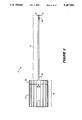
- FIG. 1 illustrates the bevelled angle of the optical fiber according to the invention.
- FIG. 2 illustrates the cylindrical probe and housing according to the invention.
- FIG. 3 illustrates a cross-sectional area of one end of the cylindrical probe.
- FIG. 4 is a cross-sectional side view of the instrument according to a second embodiment.
- FIG. 5 is a side view of the travel limiting means of the housing according to the invention.
- FIGS. 6 and 7 are end views of the travel limiting means of the housing according to the invention.
- FIG. 8 illustrates the probe portion of the housing according to the invention.
- FIG. 9 illustrates the probe portion of the housing in a cross-sectional view along the length of the housing.
- FIG. 10 illustrates an enlarged view of one part of FIG. 9.
- FIG. 11 illustrates a cross-sectional view of the probe portion of the housing along section 11--11 of FIG. 8.
- FIG. 12 illustrates a side view of an aspiration connector according to the invention.
- FIG. 13 illustrates the optical fiber attached to an aspiration connector and associated tubing according to the invention.
- FIG. 14 illustrates the aspiration connector of FIG. 13 installed in the housing.
- FIG. 15 illustrates the optical fiber attached to an aspiration connector and associated tubing and having a transparent cap.
- FIG. 16 illustrates a cross-sectional view of the closed end of the cylindrical probe having the optical fiber with a transparent cap thereon.
- FIG. 17 illustrates the bevelled end of the optical fiber with a transparent cap enclosing the bevelled end in cross-section.
- FIG. 18 is a cross-sectional view of an optical fiber inside a cylindrical probe taken along line 18--18 of FIG. 4.
- FIG. 19 is a cross-sectional view of the optical fiber and transparent cap taken along line 19--19 of FIG. 16.
- FIG. 20 is a plan view of an aspiration clamp, aspiration tubing and diverter.
- FIG. 21a is a plan view of a cylindrical probe in another embodiment of the invention.
- FIG. 21b is a cross-sectional view of the cylindrical probe in FIG. 21a.
- FIG. 22a is a plan view of an optical fiber in another embodiment of the invention.
- FIG. 22b is a plan view of an optical fiber in another embodiment of the invention.
- FIG. 23 is a sectional view of an optical fiber in another embodiment of the invention.
- FIG. 24 is a sectional view of an optical fiber in another embodiment of the invention.
- Optical fiber 5 is a glass clad quartz fiber 400 microns in diameter in one embodiment.
- a bundle of optical fibers can be used to direct light at an angle to the axis of the bundle.
- the optical fiber 5 has one bevelled end 16.
- the angle of incidence A at which the end 16 is bevelled depends upon the critical angle (not shown) as calculated from the indices of refraction of the quartz fiber material and the medium surrounding the bevelled end 16.
- the angle A is greater than the calculated critical angle so that the incident light along the center line fiber axis is totally internally reflected at an angle C to the fiber axis in one embodiment.
- the critical angle is determined from well known laws of optics.
- the angle A refracts light at an angle to the fiber's axis, depending on the application of the instrumentation.
- the medium surrounding the bevelled end 16 is a liquid or a pure gas or a mixture of gases, such as air, preferably so that the ration of indices of refraction is large.
- One ratio of indices of refraction is that of quartz to air, i.e., 1.44 to 1.
- the method of directing light at an angle comprises providing a bevel on one end 16 of an otherwise conventional optical fiber 5 so that the bevelled end reflects light at an angle to the fiber axis rather than refracts light.
- apparatus 1 for diskectomy surgery i.e., repair of inter-vertebral disks
- apparatus 1 for diskectomy surgery comprises a long cylindrical probe 2, approximately 8.6 inches long, 12 gauge outside diameter having a central bore approximately 0.054 inch in diameter and a closed end 4 in one embodiment.
- Apparatuses having other dimensions are used for other surgical procedures or other applications (including non-surgical).
- the invention is not limited to particular dimensions or application.
- the cylindrical probe 2 introduces optical fiber 5 (shown in an enlarged cross-sectional view in FIG. 4) into the body of a patient.
- the optical fiber 5 transmits light (such as laser light) to the area of interest inside the patient, such as the nucleus of the patient's vertebral disk.
- the closed end 4 of the cylindrical probe 2 is inserted through a conventional surgical cannula (not shown), having an inside diameter larger than the outside diameter of probe 2, to the area of interest in the patient's body.
- a conventional surgical cannula (not shown), having an inside diameter larger than the outside diameter of probe 2, to the area of interest in the patient's body.
- the large diameter cannula and other insertion instrumentation used in percutaneous diskectomy, for example, is described in more detail in co pending and commonly owned U.S. patent application Ser. No. 07/463,758, filed Jan. 12, 1990 attorney docket no. M-1139, hereby incorporated by reference.
- the cylindrical probe 2 is made from a surgical stainless steel, preferably 304 stainless steel, full hard, and is coated with titanium nitride to provide a lubricous coating deposited by physical vapor deposition to 2-3 mil. thick in one embodiment.
- the lubricous coating helps prevent tissue from sticking to the probe 2, especially when the probe 2 is hot, such as when laser light is
- FIG. 3 is an enlarged cross-sectional view of closed end 4 along the length of probe 2.
- the cylindrical probe 2 has a cut-out 6 in one side of probe 2 near closed end 4. Cut-out 6 has a radius of curvature R of approximately 0.156 inches.
- the cylindrical probe 2 has a plurality (such as nine) of smoke aspiration holes 7a near the closed end 4 in one embodiment. Aspiration holes 7a are approximately 0.031 inches in diameter and staggered around the perimeter of probe 2 approximately 120 degrees apart in one embodiment. Cutout 6 and aspiration holes 7a are continuous with the central bore of probe 2.
- FIG. 5 is a side view of one embodiment of the mechanism for limiting travel 10 having base 10b shown in cross-section.
- FIGS. 6 and 7 are opposite end views of the travel limiting mechanism 10.
- the mechanism for limiting travel 10 has an extension, which is a plurality of extension fingers 10a (such as six figures) in one embodiment, integrally connected to a base 10b to extend from one side thereof.
- Base 10b is circular in shape and has a plurality of gripping ribs 10f (such as eighteen ribs) along the outside perimeter of base 10b.
- the end of the extension opposite base 10b has projection 14 extending radially outward therefrom.
- the extension fingers 10a of the embodiment illustrated in FIGS. 5-7 each have a projection 14 and an internal and external radius.
- the extension is sized and configured to fit within housing 9. For example, extension fingers 10a are compressed inward slightly to insert mechanism 10 into housing 9.
- the extension is a hollow cylinder integrally connected to base 10b.
- the end of the extension, which is opposite the base 10b, has a tapered projection and a thinner cross section than the rest of the extension. The tapered projection and thinner cross section facilitates insertion of the mechanism 10 into housing 9.
- Probe portion 11 of housing 9 is illustrated in FIGS. 8-11.
- FIG. 8 is a side view of the probe portion 11.
- FIG. 9 is a cross-sectional view of probe portion 11 taken along the length thereof.
- FIG. 10 is an enlarged view of a portion of FIG. 9 encircled and labeled with reference numeral 10.
- FIG. 11 is a cross-sectional view of probe portion 11 taken along line 11--11 of FIG. 8.
- Probe portion 11 of housing 9 is a cylindrical tube approximately 1.6 inches long having a central bore of varying diameters along its length and a plurality of gripping ribs, such as eighteen ribs as described above for ribs 10f.
- the smallest diameter of the central bore is sized to accommodate optical fiber 5 therethrough and the largest diameter is sized to accommodate the mechanism for limiting travel 10.
- One end 11a receives the extension of the mechanism for limiting travel 10 and includes a lip 11k located on the inside perimeter of end 11a to contact the projections(s) of the extension, depending on the embodiment.
- End 11a of probe portion 11 also has probe 2 receiving hole 11b which extends approximately halfway along the length of housing 9 and has a slightly larger diameter at end 11a.
- the other end of probe receiving hole 11b has a neck 11c adjacent to an aspiration connector receiving hole 11d.
- Aspiration connector receiving hole 11d has a larger diameter than probe receiving hole 11b for receiving aspiration connector 12 (described in more detail below).
- Hole 11d has a connector stop 11e adjacent to aspiration hole portion 11f located adjacent neck 11c and connector stop 11e.
- FIG. 10 is an enlarged view detailing the portion of probe housing where neck 11c, aspiration hole portion 11f, and connector stop 11e are located.
- Hole 11d further includes flat step 11g which keys with flat step 12g on aspiration connector 12 (described below).
- Hole 11d terminates in a recessed location in housing 9 near end 11h. The opening in probe portion 11 is much wider at end 11h than the hole 11d and extension branches 11i connect between end 11h of housing 9 and the hole 11d in one embodiment.
- FIG. 11 illustrates, in cross section along line 11--11 of FIG. 8, end 11h of housing 9 and shows scalloped cut-outs 13 along with flat step 11g. Scalloped cut-outs 13 accommodate the shape of scalloped edges 12h of the aspiration connector 12.
- Probe portion 11 of housing 9 receives an aspiration connector 12 as illustrated in FIGS. 12 and 13.
- aspiration connector 12 is cylindrical in shape and has a tubing connector 12a at one end.
- the tubing connector 12a has a ribbed male fitting which attaches to aspiration tubing and a flared neck having scalloped edges 12h.
- aspiration connector 12 has flat step 12g which keys together with flat step 11g of housing 9.
- An aspiration and fiber receiving central bore 12c extends through connector 12.
- channels connect central bore 12c to ports leading outside of connector 12.
- Channel 12e connects with the aspiration system described below and channel 12f is a path into which adhesive is applied to hold an optical fiber in place in aspiration connector 12. When adhesive is applied via channel 12f, adhesive fills the channel and flows into central bore 12c to contact the fiber and adhere the fiber to connector 12.
- Aspiration connector 12 further includes channel 12d, providing a pathway connecting hole 11f and channel 12e of the aspiration system.
- the aspiration pathway is diverted from central bore 12c along channel 12d to bypass the adhesive at position 12f in central bore 12c.
- the aspiration system is used with vaporization devices that direct light in a straight line and vaporization devices that direct light at an angle to the fiber's axis, thereby providing a tissue vaporization device having an aspiration passageway essentially coaxial with the optical fiber. See commonly owned patent application entitled “Laser Surgery Aspiration Technique” by Henry H. Fletcher, attorney docket number M-1511 U.S., filed Mar. 7, 1991, Ser. No. 07/666,095, incorporated herein by reference.
- optical fiber 5 is inserted through central bore 12c of aspiration connector 12 to extend for a distance from one end, while aspiration tubing 18 is installed on tubing receiving end 12a of aspiration connector 12 from the other end.
- Optical fiber 5 is coaxial with aspiration tubing 18 to a point where tubing 18 is connected to a diverter 19 as illustrated in FIG. 20 and described further below.
- optical fiber 5 is permanently installed in receiving hole 12c of aspiration connector 12 with an adhesive, such as cyanoacrylate, applied via channel 12f, as mentioned above.
- Aspiration connector 12 and optical fiber 5 are installed together in housing 9 through end 11h.
- FIG. 14 illustrates housing 9 assembled with aspirator connector 12, according to one embodiment.
- Flat step 12g abuts flat step 11g inside housing 9 thereby automatically orienting aspiration connector 12 to housing 9 both rotationally and axially in a single way.
- cylindrical probe 2 is installed from end 11a into probe receiving hole 11b.
- Cylindrical probe 2 is permanently installed into housing 9 using an adhesive, such as a cyanoacrylate, to hold probe 2 in place in one embodiment. Excess adhesive accumulates in the wider taper at end 11a of probe receiving hole 11b.
- optical fiber 5 (not shown in FIG. 14) is inserted first through end 11h to feed through the central bore extending from end 11h to end 11a of housing 9 and feed into cylindrical probe 2.
- Optical fiber 5 extends into cylindrical probe 2 for a predetermined distance depending on the length of the cylindrical probe.
- Aspiration connector 12 is rotationally keyed into aspiration connector receiving hole 11d, as described above, so that the bevelled end 16 of optical fiber 5, according to the invention, is aligned with cut-out 6 at the closed end 4 of cylindrical probe 2, as illustrated in FIG. 4.
- Optical fiber 5 has a single orientation when installed and bonded into aspiration connector 12 so that when aspiration connector 12 and optical fiber 5 are installed in housing 9, the orientation of the bevelled end 16 of optical fiber 5 is as described above.
- Aspiration connector 12 is held in place in housing 9 with adhesive, such as a cyanoacrylate.
- the mechanism for limiting ravel 10 is inserted into probe portion 11 from end 11a to form housing 9 prior to the installation of aspiration connector 12.
- Base 10b on means for limiting travel 10 has an opening 10d with oppositely located projection receiving portions 10c. Opening 10d and portions 10c receive a connector (not shown) of the large cannula (not shown).
- the large cannula connector fits into hole 10d and projecting teeth of the large cannula connector fit into portions 10c. Housing 9 is then rotated until the projecting teeth of the large cannula connector contact stops 10e, as illustrated in FIG. 6, thereby twist locking the instrumentation 1 into place.
- the cylindrical probe 2 and optical fiber 5 rotate together clockwise or counterclockwise, but move axially forward and backward in the large cannula only a limited distance determined by the length of extension fingers 10a.
- the instrumentation is rotated by rotating probe portion 11 while the mechanism for limiting travel remains stationary and locked to the large cannula.
- the length of the extension on the mechanism for limiting travel 10 prevents instrumentation 1 from being completely withdrawn from the large cannula without unlocking the travel limiting mechanism 10 from the large cannula connector.
- the instrumentation 1 remains locked to the large cannula so that this travel limitation prevents damage to the large cannula and the internal surrounding area in the patient by the laser beam.
- the laser is turned off before the instrumentation 1 is disconnected from the large cannula to accommodate this safety feature.
- the transparent cap 17 serves three functions: first, the transparent cap 17 protects the bevelled end 16 of the fiber 5 against contamination. Contamination on the fiber creates hot spots when transmitting laser energy. The hot spots create stress points which can damage the fiber. Second, the transparent cap 17 ensures the critical angle remains constant by trapping the medium surrounding the bevelled end 16. The transparent cap 17 eliminates undesirable refractive index matching due to fluids contacting bevelled end 16 by separating the bevelled end 16 from the fluid environment. Third, the transparent cap 17 acts as a lens, moving the focal point of the laser light further away from the surface of the cylindrical probe 2.
- FIGS. 18 and 19 are cross sectional views taken along line 18--18 and 19--19 of FIGS. 4 and 16, respectively, where the fiber 5 is bevelled.
- the focal points f 2 and f 1 with and without the transparent cap 17, respectively, are shown by dashed lines.
- the light is focused further away from the assembly using a transparent cap 17, as shown in FIG. 19, because the focal point distance is proportional to the larger radius of the transparent cap 17 in FIG. 19 as compared to the radius of the fiber in FIG. 18.
- the light emanating from the fiber 5 through the transparent cap 17 has a unique output which reflects from the bevelled end 16, focusses on transparent cap 17 and defocuses as it emanates from the cut-out 6 of the probe 2.
- FIGS. 13 and 15 illustrate that the optical fiber 5 is attached to aspiration connector 12.
- the optical fiber extends coaxially with the aspiration tubing 18 to where aspiration tubing 18 connects to a Y-shaped diverter 19 having three ports 19a-c as illustrated in FIG. 20.
- the diverter 19 attaches tubing 18 and tubing 20 having optical fiber 5 disposed coaxially therethrough to a laser, according to the preferred embodiment, via clamping connector 21.
- Clamping connector 21 aligns optical fiber 5 to the laser output beam as described in detail in commonly owned R. Losch et al. U.S. Pat. No. 4,722,337 issued Feb. 2, 1988, which is a continuation-in-part of commonly owned P. Hertzmann U.S. Pat. No. 4,580,557, both incorporated by reference herein.
- instrumentation I comprises directing laser light along optical fiber 5 to reflect from bevelled end 16 and through cut-out 6 in cylindrical probe 2 to a target area, as mentioned above.
- the laser light vaporizes, coagulates and severs tissue and minimizes blood flow at the target site.
- paths of vaporized tissue are created which approach a cylindrical shape as the instrument is rotated 360 degrees and is moved axially. Smaller areas are vaporized by limiting the rotation and axial movement of the instrumentation.
- Residual smoke, steam, and fine particulates from the vaporized tissue are removed from the affected area by providing vacuum along the same path as the optical fiber from diverter 19 (see FIG. 20).
- the vacuum draws in smoke through cut-out 6 and smoke aspiration holes 7a.
- the smoke follows the aspiration pathway created by the central bore of probe 2 coaxially with optical fiber 5.
- the smoke exits probe 2 at evacuation hole 11f in housing 9 to flow down channel 12d of aspiration connector 12 until channel 12e where the smoke enters central bore 12c to be evacuated out tubing 18.
- the aspiration pathway is coaxial with optical fiber 5 to hole 11f where the aspiration pathway is diverted around the adhesive holding optical fiber 5 in central bore 12c of aspiration connector 12.
- the aspiration pathway returns to a coaxial pathway with optical fiber 5 at channel 12e.
- the smoke is drawn through connector 12a of aspiration connector 12 and through tubing 18 until diverter 19, as illustrated in FIG. 20, where the coaxial pathway ends and aspirated smoke exits via path 19b connected to a source of vacuum relative to path 19c where the fiber 5 connects to the laser.
- Scalloped cut-outs 13 of housing 9 (see FIGS. 9 and 11) and scalloped edges 12h of aspiration connector 12 provide entry points (air leak points) where air can enter housing 9 and mix with the smoke in the aspiration path described above. Air mixes with smoke and particulates of the vaporized tissue near channels 12e and 12d and is drawn into hole 12e to be evacuated as described above. The air leaks at scalloped cut-outs 13 and edges 12h minimize the vacuum at cut-out 6 and aspiration holes 7a so that only smoke, steam and fine particulates of the vaporized tissue (and not tissue fragments) are drawn into cylindrical probe 2.
- the method of making the optical fiber 5 for directing light at an angle C (see FIG.
- a plastic clad or a glass clad optical fiber can be used for the invention.
- the plastic cladding must be stripped back.
- the glass cladding is essentially a layer of glass over the fiber that allows light to reflect off the inside surface of the junction with the fiber and is not removed.
- the medium surrounding the bevelled tip 16 in one embodiment has an index of refraction different from the index of refraction of the quartz optical fiber 5.
- the ratio of indices of refraction is preferable as high as possible so that the bevelled angle internally reflects the light beam, nearly perpendicular to the fiber's axis.
- the bevelled angle is 38+ /- 2 degrees when the surrounding medium is air.
- the light beam is reflected from the bevelled end 16, preferable 60-90 degrees, although other angles may be useful in other applications and this invention is not limited to any particular angle of reflection.
- the method of making the optical fiber 5 further includes enclosing the bevelled end 16 with a transparent cap 17.
- the transparent cap 17 is quartz in one embodiment and is sealed to the optical fiber by first, stripping back a thermoplastic jacketing material 28 on the optical fiber 5; second, inserting the transparent cap 17 over the bevelled end 16; and third, attaching the transparent cap 17 to the fiber 5, such as with laser energy to fuse the transparent cap 17 to the fiber 5 in one embodiment.
- the transparent cap 17 is bonded with a high temperature adhesive to create a hermetic seal.
- a thermoplastic (preferably polyimide) coating 30 is applied to the stripped area 31 to provide structural strength to the optical fiber in the exposed prestripped area 31, as illustrated in FIGS. 16 and 17.
- the medium sealed inside the transparent cap 17 when the transparent cap 17 is installed is air in one embodiment.
- the transparent cap 17 is installed in open air or in a controlled atmosphere, such as a sealing chamber/vacuum chamber or a dry box having a known content of moisture, so that the medium trapped in cap 17 is determined with accuracy.
- Transparent cap 17 is employed to ensure that a gaseous condition exists at the bevelled end 16 of optical fiber 5.
- FIGS. 23 and 24 illustrate an embodiment of the invention eliminating transparent cap 17.
- angle 34 Positioned adjacent to bevelled end 16 is a bevelled plug 32, with one end of each in either a contacting relationship, or alternatively a very tight fit close enough to effectively trap fluid between the two surfaces.
- the two bevelled pieces are positioned adjacent to one another in such a manner as to create an angle 34 which is preferably about from 0.01 to 10 degrees. More preferably, angle 34 is from about 0.01 to 5 degrees, and most preferably 0.1 to 2 degrees.
- volume 36 is created between the two bevelled surfaces.
- Volume 36 is filled with fluid when the laser is not firing but the fluid becomes quickly vaporized when it is fired.
- volume 36 between the bevelled surfaces decreases, less energy is needed to vaporize the liquid to the gaseous state.
- volume 36 increases in size, it becomes more difficult to achieve sufficient vaporization of the liquid in that area.
- Volume 36 is determined by the size of angle 34, distance 38 between the two bevelled surfaces, diameter of optical fiber 5 and cross sectional dimension of bevelled plug 32.
- Volume 36 should be of a size which holds enough fluid, all of which substantially becomes vaporized to a gaseous state when the laser is fired.
- Optical fiber 5 diameter can vary from 1,000 to about 200, 100 or even 50 microns.
- the cross sectional dimension of bevelled plug 32 approximates the corresponding surface area of bevelled end 16. However, the two can be different as long as the liquid contained in volume 36 is capable of becoming vaporized.
- the cross sectional dimension of bevelled plug 32 can be larger or smaller than the corresponding fiber, and vary from 1,000 to about 200, 100 or 50 microns.
- Bevelled plug 32 can be made of quartz, stainless steel or the like. Bevelled plug 32 protects bevelled end 16 against contamination and breakage.
- End 40 of bevelled plug 32 can be flat, rounded or have other geometric configurations.
- optical fiber 5 is inserted through central bore 12c of aspiration connector 12 to extend for a distance from one end, while aspiration tubing 18 is installed on tubing receiving end 12a of aspiration connector 12 from the other end.
- Optical fiber 5 is coaxial with aspiration tubing 18 to a point where tubing 18 is connected to a diverter 19 as illustrated in FIG. 20.
- optical fiber 5 is permanently installed in receiving hole 12c of aspiration connector 12 with an adhesive, such as a cyanoacrylate, applied via channel 12f.
- aspiration connector 12 and optical fiber 5 are installed together in housing 9 through end 11h.
- FIG. 14 illustrates housing 9 assembled with aspirator connector 12, according to one embodiment.
- Bevelled plug 32 can be retained in cylindrical probe 2 by welding or an adhesive.
- bevelled plug 32 and bevelled end 16 of optical fiber 5 are maintained in a parallel relationship, with a minimal gap between the two surfaces. This reduces the likelihood of contaminants interfering with the operation of the laser at bevelled end 16.
- Optical fiber 5 and bevelled plug 32 can be initially bonded with a limited amount of adhesive, such as cyanoacrylate, in order the bring the two in a stationary position while maintained at an elevated temperature. During cooling, the differences in the respective coefficients of expansion of bevelled plug 32 and optical fiber 5 causes a separation and creating a very narrow gap 42, about 10 to 1,000 microns, and more preferably about 10 to 50 microns.
- the gap is so small that a gaseous environment is created in volume 36 when sufficient energy is transmitted through optical fiber 5.
- the laser light effectively reflects off of bevelled end 16 without the need for encapsulation. Additionally, index matching of the fluid or contaminants with optical fiber 5 is avoided.
- Both bevelled end 16 and bevelled plug 32 can be conventionally grinded and polished to the desired angle and are made optically clear.
- a diamond lapping wheel can be used to grind and polish. Residual smoke, steam, and fine particulates from the vaporized tissue are removed by providing vacuum along the same path as optical fiber 5. Vacuum draws smoke in through cut-outs and aspiration holes 7a as shown in FIG. 14. The aspiration pathway is coaxial with optical fiber 5 as recited above.
- bevelled plug 32 is useful for micro surgical applications including but not limited to eye, ear, brain and other small delicate areas where access is difficult.
- FIG. 21a illustrates a side view of cylindrical probe 2a and optical fiber 5a.
- FIG. 21b is a cross-sectional view of cylindrical probe 2a having optical fiber 5a disposed therein.
- Cylindrical probe 2a has a sharp tip at closed end 4a.
- the optical fiber 5a is inserted into cylindrical probe 2a so that the bevelled end 16a is adjacent the sharp tip 4a.
- the sharp tip 4a penetrates tissue, such as a nasal polyp, and embeds within the tissue.
- Light is transmitted through optical fiber 5a and directed a an angle through cut-out 6a to the polyp tissue.
- the cylindrical probe 2a is rotatable through 360 degrees one or more times to treat an affected area.
- a laser light from a frequency-doubled Nd:YAG laser at 532 nm wavelength is used to vaporize the polyp tissue.
- an area of vaporized tissue is created as the cylindrical probe 2a is rotated and the remaining tissue shrinks around the vaporized area.
- FIGS. 22a and 22b Another aspect of the invention is illustrated in FIGS. 22a and 22b.
- Optical fiber 5b illustrated in FIG. 22a, is ground and polished to form a bevelled end 5c.
- a reflective coating 5d is deposited on the bevelled end 5c of optical fiber 5b and adjacent sides, except for area 5e adjacent to end 5c. Area 5e is masked off during the deposition step to keep area 5e uncoated.
- light is directed by optical fiber 5b to end 5c wherein the bevelled angle and reflective coating reflect the light at an angle to the fiber's axis, out through uncoated area 5e.
- the bevelled angle depends only on the angle at which the light is to be reflected and is determined from well known laws of optics. Disadvantageous index matching is eliminated by the reflecting coating 5d.
- the reflective coating 5d improves internal reflection of light so that substantially all the light reflected is directed along one path through the uncoated area. This aspect of the invention controls the reflected light better than the embodiments described above.
- the reflective coating 5d is silver.
- layers of SiO 2 /TiO 2 make up reflective coating 5d. The reflective coating is deposited on the fiber by well known deposition techniques, such as sputtering.
Abstract
Description
Claims (16)
Priority Applications (1)
| Application Number | Priority Date | Filing Date | Title |
|---|---|---|---|
| US07/929,187 US5257991A (en) | 1990-11-15 | 1992-08-11 | Instrumentation for directing light at an angle |
Applications Claiming Priority (2)
| Application Number | Priority Date | Filing Date | Title |
|---|---|---|---|
| US61435890A | 1990-11-15 | 1990-11-15 | |
| US07/929,187 US5257991A (en) | 1990-11-15 | 1992-08-11 | Instrumentation for directing light at an angle |
Related Parent Applications (1)
| Application Number | Title | Priority Date | Filing Date |
|---|---|---|---|
| US61435890A Continuation-In-Part | 1990-11-15 | 1990-11-15 |
Publications (1)
| Publication Number | Publication Date |
|---|---|
| US5257991A true US5257991A (en) | 1993-11-02 |
Family
ID=27087223
Family Applications (1)
| Application Number | Title | Priority Date | Filing Date |
|---|---|---|---|
| US07/929,187 Expired - Lifetime US5257991A (en) | 1990-11-15 | 1992-08-11 | Instrumentation for directing light at an angle |
Country Status (1)
| Country | Link |
|---|---|
| US (1) | US5257991A (en) |
Cited By (86)
| Publication number | Priority date | Publication date | Assignee | Title |
|---|---|---|---|---|
| US5366456A (en) * | 1993-02-08 | 1994-11-22 | Xintec Corporation | Angle firing fiber optic laser scalpel and method of use |
| WO1994026185A1 (en) * | 1993-05-14 | 1994-11-24 | Boston Scientific Corporation | Laser treatment of tissue using optical radiation |
| WO1995008297A1 (en) * | 1993-09-20 | 1995-03-30 | Abela Laser Systems, Inc. | Cardiac ablation catheters and method |
| US5454794A (en) * | 1993-10-15 | 1995-10-03 | Pdt Systems, Inc. | Steerable light diffusing catheter |
| US5495541A (en) * | 1994-04-19 | 1996-02-27 | Murray; Steven C. | Optical delivery device with high numerical aperture curved waveguide |
| US5498260A (en) * | 1993-02-08 | 1996-03-12 | Xintec Corporation | Internal reflectance angle firing fiber optic laser delivery device and method of use |
| US5537499A (en) * | 1994-08-18 | 1996-07-16 | Laser Peripherals, Inc. | Side-firing laser optical fiber probe and method of making same |
| US5562657A (en) * | 1994-09-19 | 1996-10-08 | Griffin; Stephen E. | Side fire laser catheter method and apparatus |
| US5593404A (en) * | 1992-08-11 | 1997-01-14 | Myriadlase, Inc. | Method of treatment of prostate |
| US5651783A (en) * | 1995-12-20 | 1997-07-29 | Reynard; Michael | Fiber optic sleeve for surgical instruments |
| US5772657A (en) * | 1995-04-24 | 1998-06-30 | Coherent, Inc. | Side firing fiber optic laser probe |
| US5807389A (en) * | 1991-08-16 | 1998-09-15 | Myriadlase, Inc. | Laterally reflecting tip for laser transmitting fiber |
| US5835649A (en) * | 1997-06-02 | 1998-11-10 | The University Of British Columbia | Light directing and collecting fiber optic probe |
| US6134460A (en) * | 1988-11-02 | 2000-10-17 | Non-Invasive Technology, Inc. | Spectrophotometers with catheters for measuring internal tissue |
| WO2000048525A3 (en) * | 1999-02-19 | 2000-12-14 | Scimed Life Systems Inc | Laser lithotripsy device with suction |
| WO2000042906A3 (en) * | 1999-01-22 | 2001-01-11 | Massachusetts Inst Technology | Fiber optic needle probes for optical coherence tomography imaging |
| US6421164B2 (en) | 1991-04-29 | 2002-07-16 | Massachusetts Institute Of Technology | Interferometeric imaging with a grating based phase control optical delay line |
| US6445939B1 (en) | 1999-08-09 | 2002-09-03 | Lightlab Imaging, Llc | Ultra-small optical probes, imaging optics, and methods for using same |
| US6485413B1 (en) | 1991-04-29 | 2002-11-26 | The General Hospital Corporation | Methods and apparatus for forward-directed optical scanning instruments |
| US6517531B2 (en) | 2001-04-27 | 2003-02-11 | Scimed Life Systems, Inc. | Medical suction device |
| US6554824B2 (en) | 2000-12-15 | 2003-04-29 | Laserscope | Methods for laser treatment of soft tissue |
| US20030130649A1 (en) * | 2000-12-15 | 2003-07-10 | Murray Steven C. | Method and system for treatment of benign prostatic hypertrophy (BPH) |
| US20030135205A1 (en) * | 2000-12-15 | 2003-07-17 | Davenport Scott A. | Method and system for photoselective vaporization of the prostate, and other tissue |
| US6620154B1 (en) * | 1990-11-07 | 2003-09-16 | Lares Research | Laser surgical probe |
| US20030216717A1 (en) * | 2002-02-22 | 2003-11-20 | Laserscope | Method and system for photoselective vaporization for gynecological treatments |
| US6708048B1 (en) | 1989-02-06 | 2004-03-16 | Non-Invasive Technology, Inc. | Phase modulation spectrophotometric apparatus |
| US20050281530A1 (en) * | 1995-08-31 | 2005-12-22 | Rizoiu Ioana M | Modified-output fiber optic tips |
| US7039454B1 (en) * | 1999-03-29 | 2006-05-02 | Hitachi Medical Corporation | Biological optical measuring instrument |
| US20060132790A1 (en) * | 2003-02-20 | 2006-06-22 | Applied Science Innovations, Inc. | Optical coherence tomography with 3d coherence scanning |
| WO2005070153A3 (en) * | 2004-01-08 | 2006-07-13 | Biolase Tech Inc | Modified-output fiber optic tips |
| US20070263975A1 (en) * | 2005-01-10 | 2007-11-15 | Biolase Technology, Inc. | Modified-output fiber optic tips |
| EA009501B1 (en) * | 2005-01-27 | 2008-02-28 | Эмиль Наумович Соболь | A laser instrument for correction nasal septum |
| US20080051770A1 (en) * | 2006-08-22 | 2008-02-28 | Synergetics, Inc. | Multiple Target Laser Probe |
| US20080219629A1 (en) * | 2004-01-08 | 2008-09-11 | Blolase Technology, Inc. | Modified-output fiber optic tips |
| US20080287934A1 (en) * | 2007-05-15 | 2008-11-20 | Hunter Lowell D | Laser Handle and Fiber Guard |
| US20080287940A1 (en) * | 2007-05-14 | 2008-11-20 | Hunter Lowell D | Fiber Pole Tip |
| WO2008154006A1 (en) * | 2007-06-08 | 2008-12-18 | Cynosure, Inc. | Coaxial suction system for laser lipolysis |
| US20090034927A1 (en) * | 2004-04-08 | 2009-02-05 | Burak Temelkuran | Photonic crystal fibers and medical systems including photonic crystal fibers |
| US20090041924A1 (en) * | 2005-05-02 | 2009-02-12 | Gregory Steube | Hard coated cannula and methods of manufacturing same |
| US20090182315A1 (en) * | 2007-12-07 | 2009-07-16 | Ceramoptec Industries Inc. | Laser liposuction system and method |
| US20090227998A1 (en) * | 2008-03-06 | 2009-09-10 | Aquabeam Llc | Tissue ablation and cautery with optical energy carried in fluid stream |
| WO2009158073A1 (en) * | 2008-06-26 | 2009-12-30 | Boston Scientific Scimed, Inc. | Laser fiber capillary apparatus and method |
| US20100016845A1 (en) * | 2008-05-19 | 2010-01-21 | Brian Hanley | Method and apparatus for protecting capillary of laser fiber during insertion and reducing metal cap degradation |
| US20100256619A1 (en) * | 2003-05-30 | 2010-10-07 | Warsaw Orthopedic, Inc. | Methods and Devices for Transpedicular Discectomy |
| WO2010118333A3 (en) * | 2009-04-09 | 2011-02-17 | Ceramoptec Industries, Inc. | Medical laser treatment device and method utilizing total reflection induced by radiation |
| US20110152619A1 (en) * | 2009-12-17 | 2011-06-23 | Boston Scientific Scimed, Inc. | Methods and apparatus related to an optical fiber member having a removable cover |
| US20110206321A1 (en) * | 2010-02-22 | 2011-08-25 | Boston Scientific Scimed, Inc. | Methods and apparatus related to a side-fire optical fiber having a robust distal end portion |
| US8291915B2 (en) | 1997-03-04 | 2012-10-23 | Tyco Healthcare Group Lp | Method and apparatus for treating venous insufficiency using directionally applied energy |
| US8435235B2 (en) | 2007-04-27 | 2013-05-07 | Covidien Lp | Systems and methods for treating hollow anatomical structures |
| US20130345686A1 (en) * | 2011-12-01 | 2013-12-26 | Joe Denton Brown | End Fire Fiber Arrangements with Improved Erosion Resistance |
| WO2014162289A1 (en) * | 2013-04-03 | 2014-10-09 | Koninklijke Philips N.V. | Photonic needle with optimal bevel angle |
| US8915948B2 (en) | 2002-06-19 | 2014-12-23 | Palomar Medical Technologies, Llc | Method and apparatus for photothermal treatment of tissue at depth |
| US9028536B2 (en) | 2006-08-02 | 2015-05-12 | Cynosure, Inc. | Picosecond laser apparatus and methods for its operation and use |
| US9063299B2 (en) | 2009-12-15 | 2015-06-23 | Omni Guide, Inc. | Two-part surgical waveguide |
| US9232960B2 (en) | 2007-01-02 | 2016-01-12 | Aquabeam, Llc | Minimally invasive devices for multi-fluid tissue ablation |
| US9510853B2 (en) | 2009-03-06 | 2016-12-06 | Procept Biorobotics Corporation | Tissue resection and treatment with shedding pulses |
| US20170128133A1 (en) * | 2015-11-07 | 2017-05-11 | Douglas Arthur Pinnow | Apparatus and methods for side-fire optical fiber device suitable for medical applicatons |
| US9780518B2 (en) | 2012-04-18 | 2017-10-03 | Cynosure, Inc. | Picosecond laser apparatus and methods for treating target tissues with same |
| JP2018517120A (en) * | 2015-03-06 | 2018-06-28 | マイクロマス ユーケー リミテッド | In vivo endoscopic tissue identification device |
| CN108882920A (en) * | 2016-02-13 | 2018-11-23 | 普渡研究基金会 | Optoacoustic conduit and the imaging system for using the optoacoustic conduit |
| US10245107B2 (en) | 2013-03-15 | 2019-04-02 | Cynosure, Inc. | Picosecond optical radiation systems and methods of use |
| US10434324B2 (en) | 2005-04-22 | 2019-10-08 | Cynosure, Llc | Methods and systems for laser treatment using non-uniform output beam |
| US10448966B2 (en) | 2010-02-04 | 2019-10-22 | Procept Biorobotics Corporation | Fluid jet tissue resection and cold coagulation methods |
| US10524822B2 (en) | 2009-03-06 | 2020-01-07 | Procept Biorobotics Corporation | Image-guided eye surgery apparatus |
| US10603109B2 (en) * | 2015-11-07 | 2020-03-31 | Douglas A. Pinnow | Apparatus and methods for side-fire optical fiber assembly suitable for medical applications |
| US10653438B2 (en) | 2012-02-29 | 2020-05-19 | Procept Biorobotics Corporation | Automated image-guided tissue resection and treatment |
| US10722308B2 (en) | 2017-07-06 | 2020-07-28 | Boston Scientific Scimed, Inc. | Optical fibers and associated systems |
| US10777397B2 (en) | 2015-03-06 | 2020-09-15 | Micromass Uk Limited | Inlet instrumentation for ion analyser coupled to rapid evaporative ionisation mass spectrometry (“REIMS”) device |
| US10777398B2 (en) | 2015-03-06 | 2020-09-15 | Micromass Uk Limited | Spectrometric analysis |
| US10916415B2 (en) | 2015-03-06 | 2021-02-09 | Micromass Uk Limited | Liquid trap or separator for electrosurgical applications |
| US10978284B2 (en) | 2015-03-06 | 2021-04-13 | Micromass Uk Limited | Imaging guided ambient ionisation mass spectrometry |
| US11031223B2 (en) | 2015-09-29 | 2021-06-08 | Micromass Uk Limited | Capacitively coupled REIMS technique and optically transparent counter electrode |
| US11031222B2 (en) | 2015-03-06 | 2021-06-08 | Micromass Uk Limited | Chemically guided ambient ionisation mass spectrometry |
| US11037774B2 (en) | 2015-03-06 | 2021-06-15 | Micromass Uk Limited | Physically guided rapid evaporative ionisation mass spectrometry (“REIMS”) |
| US11172988B2 (en) | 2016-01-27 | 2021-11-16 | Optical Integrity, Inc. | End fire fiber arrangements with improved erosion resistance |
| US11213313B2 (en) | 2013-09-06 | 2022-01-04 | Procept Biorobotics Corporation | Tissue resection and treatment with shedding pulses |
| US11239066B2 (en) | 2015-03-06 | 2022-02-01 | Micromass Uk Limited | Cell population analysis |
| US11264223B2 (en) | 2015-03-06 | 2022-03-01 | Micromass Uk Limited | Rapid evaporative ionisation mass spectrometry (“REIMS”) and desorption electrospray ionisation mass spectrometry (“DESI-MS”) analysis of swabs and biopsy samples |
| US11270876B2 (en) | 2015-03-06 | 2022-03-08 | Micromass Uk Limited | Ionisation of gaseous samples |
| US11282688B2 (en) | 2015-03-06 | 2022-03-22 | Micromass Uk Limited | Spectrometric analysis of microbes |
| US11289320B2 (en) | 2015-03-06 | 2022-03-29 | Micromass Uk Limited | Tissue analysis by mass spectrometry or ion mobility spectrometry |
| US11342170B2 (en) | 2015-03-06 | 2022-05-24 | Micromass Uk Limited | Collision surface for improved ionisation |
| US11367605B2 (en) | 2015-03-06 | 2022-06-21 | Micromass Uk Limited | Ambient ionization mass spectrometry imaging platform for direct mapping from bulk tissue |
| US11406453B2 (en) | 2009-03-06 | 2022-08-09 | Procept Biorobotics Corporation | Physician controlled tissue resection integrated with treatment mapping of target organ images |
| US11418000B2 (en) | 2018-02-26 | 2022-08-16 | Cynosure, Llc | Q-switched cavity dumped sub-nanosecond laser |
| US11454611B2 (en) | 2016-04-14 | 2022-09-27 | Micromass Uk Limited | Spectrometric analysis of plants |
Citations (6)
| Publication number | Priority date | Publication date | Assignee | Title |
|---|---|---|---|---|
| US4273109A (en) * | 1976-07-06 | 1981-06-16 | Cavitron Corporation | Fiber optic light delivery apparatus and medical instrument utilizing same |
| US4566438A (en) * | 1984-10-05 | 1986-01-28 | Liese Grover J | Fiber-optic stylet for needle tip localization |
| US4576177A (en) * | 1983-02-18 | 1986-03-18 | Webster Wilton W Jr | Catheter for removing arteriosclerotic plaque |
| WO1990005562A1 (en) * | 1988-11-16 | 1990-05-31 | Medilase, Incorporated | Angioplasty catheter with off-axis angled beam delivery fiber |
| US5078711A (en) * | 1988-08-11 | 1992-01-07 | Kabushiki Kaisha Morita Seisakusho | Laser irradiation device capable of varying irradiation angle |
| US5129895A (en) * | 1990-05-16 | 1992-07-14 | Sunrise Technologies, Inc. | Laser sclerostomy procedure |
-
1992
- 1992-08-11 US US07/929,187 patent/US5257991A/en not_active Expired - Lifetime
Patent Citations (6)
| Publication number | Priority date | Publication date | Assignee | Title |
|---|---|---|---|---|
| US4273109A (en) * | 1976-07-06 | 1981-06-16 | Cavitron Corporation | Fiber optic light delivery apparatus and medical instrument utilizing same |
| US4576177A (en) * | 1983-02-18 | 1986-03-18 | Webster Wilton W Jr | Catheter for removing arteriosclerotic plaque |
| US4566438A (en) * | 1984-10-05 | 1986-01-28 | Liese Grover J | Fiber-optic stylet for needle tip localization |
| US5078711A (en) * | 1988-08-11 | 1992-01-07 | Kabushiki Kaisha Morita Seisakusho | Laser irradiation device capable of varying irradiation angle |
| WO1990005562A1 (en) * | 1988-11-16 | 1990-05-31 | Medilase, Incorporated | Angioplasty catheter with off-axis angled beam delivery fiber |
| US5129895A (en) * | 1990-05-16 | 1992-07-14 | Sunrise Technologies, Inc. | Laser sclerostomy procedure |
Cited By (173)
| Publication number | Priority date | Publication date | Assignee | Title |
|---|---|---|---|---|
| US6134460A (en) * | 1988-11-02 | 2000-10-17 | Non-Invasive Technology, Inc. | Spectrophotometers with catheters for measuring internal tissue |
| US6708048B1 (en) | 1989-02-06 | 2004-03-16 | Non-Invasive Technology, Inc. | Phase modulation spectrophotometric apparatus |
| US6620154B1 (en) * | 1990-11-07 | 2003-09-16 | Lares Research | Laser surgical probe |
| US6485413B1 (en) | 1991-04-29 | 2002-11-26 | The General Hospital Corporation | Methods and apparatus for forward-directed optical scanning instruments |
| US6421164B2 (en) | 1991-04-29 | 2002-07-16 | Massachusetts Institute Of Technology | Interferometeric imaging with a grating based phase control optical delay line |
| US6564087B1 (en) | 1991-04-29 | 2003-05-13 | Massachusetts Institute Of Technology | Fiber optic needle probes for optical coherence tomography imaging |
| US5807389A (en) * | 1991-08-16 | 1998-09-15 | Myriadlase, Inc. | Laterally reflecting tip for laser transmitting fiber |
| US5593404A (en) * | 1992-08-11 | 1997-01-14 | Myriadlase, Inc. | Method of treatment of prostate |
| US5498260A (en) * | 1993-02-08 | 1996-03-12 | Xintec Corporation | Internal reflectance angle firing fiber optic laser delivery device and method of use |
| US5366456A (en) * | 1993-02-08 | 1994-11-22 | Xintec Corporation | Angle firing fiber optic laser scalpel and method of use |
| US5454807A (en) * | 1993-05-14 | 1995-10-03 | Boston Scientific Corporation | Medical treatment of deeply seated tissue using optical radiation |
| WO1994026185A1 (en) * | 1993-05-14 | 1994-11-24 | Boston Scientific Corporation | Laser treatment of tissue using optical radiation |
| WO1995008297A1 (en) * | 1993-09-20 | 1995-03-30 | Abela Laser Systems, Inc. | Cardiac ablation catheters and method |
| US5454794A (en) * | 1993-10-15 | 1995-10-03 | Pdt Systems, Inc. | Steerable light diffusing catheter |
| US5495541A (en) * | 1994-04-19 | 1996-02-27 | Murray; Steven C. | Optical delivery device with high numerical aperture curved waveguide |
| US5537499A (en) * | 1994-08-18 | 1996-07-16 | Laser Peripherals, Inc. | Side-firing laser optical fiber probe and method of making same |
| US5562657A (en) * | 1994-09-19 | 1996-10-08 | Griffin; Stephen E. | Side fire laser catheter method and apparatus |
| US5772657A (en) * | 1995-04-24 | 1998-06-30 | Coherent, Inc. | Side firing fiber optic laser probe |
| US20050281530A1 (en) * | 1995-08-31 | 2005-12-22 | Rizoiu Ioana M | Modified-output fiber optic tips |
| US7620290B2 (en) * | 1995-08-31 | 2009-11-17 | Biolase Technology, Inc. | Modified-output fiber optic tips |
| US5651783A (en) * | 1995-12-20 | 1997-07-29 | Reynard; Michael | Fiber optic sleeve for surgical instruments |
| US8291915B2 (en) | 1997-03-04 | 2012-10-23 | Tyco Healthcare Group Lp | Method and apparatus for treating venous insufficiency using directionally applied energy |
| WO1998055850A1 (en) * | 1997-06-02 | 1998-12-10 | The University Of British Columbia | Fiber-optic probe |
| US5835649A (en) * | 1997-06-02 | 1998-11-10 | The University Of British Columbia | Light directing and collecting fiber optic probe |
| WO2000042906A3 (en) * | 1999-01-22 | 2001-01-11 | Massachusetts Inst Technology | Fiber optic needle probes for optical coherence tomography imaging |
| US7104983B2 (en) | 1999-02-19 | 2006-09-12 | Boston Scientific Scimed, Inc. | Laser lithotripsy device with suction |
| WO2000048525A3 (en) * | 1999-02-19 | 2000-12-14 | Scimed Life Systems Inc | Laser lithotripsy device with suction |
| US20040243123A1 (en) * | 1999-02-19 | 2004-12-02 | Scimed Life Systems, Inc. | Laser lithotripsy device with suction |
| US6726681B2 (en) | 1999-02-19 | 2004-04-27 | Scimed Life Systems, Inc. | Laser lithotripsy device with suction |
| US6375651B2 (en) | 1999-02-19 | 2002-04-23 | Scimed Life Systems, Inc. | Laser lithotripsy device with suction |
| US7778694B2 (en) | 1999-03-29 | 2010-08-17 | Hitachi Medical Corporation | Biological optical measurement instrument |
| US20060184044A1 (en) * | 1999-03-29 | 2006-08-17 | Mikihiro Kaga | Biological optical measurement instrument |
| US7039454B1 (en) * | 1999-03-29 | 2006-05-02 | Hitachi Medical Corporation | Biological optical measuring instrument |
| US6445939B1 (en) | 1999-08-09 | 2002-09-03 | Lightlab Imaging, Llc | Ultra-small optical probes, imaging optics, and methods for using same |
| EP1349509A4 (en) * | 2000-12-15 | 2005-10-05 | Laserscope Inc | Methods for laser treatment of soft tissue |
| US6554824B2 (en) | 2000-12-15 | 2003-04-29 | Laserscope | Methods for laser treatment of soft tissue |
| US20040236318A1 (en) * | 2000-12-15 | 2004-11-25 | Laserscope | Method and system for photoselective vaporization of the prostate, and other tissue |
| US20030130649A1 (en) * | 2000-12-15 | 2003-07-10 | Murray Steven C. | Method and system for treatment of benign prostatic hypertrophy (BPH) |
| US20050256513A1 (en) * | 2000-12-15 | 2005-11-17 | Laserscope | Method and system for vaporization of tissue using direct visualization |
| US20040236319A1 (en) * | 2000-12-15 | 2004-11-25 | Laserscope | Method and system for photoselective vaporization of the prostate, and other tissue |
| US6986764B2 (en) | 2000-12-15 | 2006-01-17 | Laserscope | Method and system for photoselective vaporization of the prostate, and other tissue |
| US20060084959A1 (en) * | 2000-12-15 | 2006-04-20 | Laserscope | Method and system for photoselective vaporization of the prostate, and other tissue |
| US10653482B2 (en) | 2000-12-15 | 2020-05-19 | Boston Scientific Scimed, Inc. | System for vaporization of tissue |
| US20080262485A1 (en) * | 2000-12-15 | 2008-10-23 | Laserscope | Method and system for photoselective vaporization of the prostate, and other tissue |
| US20070225696A1 (en) * | 2000-12-15 | 2007-09-27 | Davenport Scott A | Surgical apparatus for laser ablation of soft tissue |
| US20030135205A1 (en) * | 2000-12-15 | 2003-07-17 | Davenport Scott A. | Method and system for photoselective vaporization of the prostate, and other tissue |
| EP1349509A1 (en) * | 2000-12-15 | 2003-10-08 | Steven C. Murray | Methods for laser treatment of soft tissue |
| US6517531B2 (en) | 2001-04-27 | 2003-02-11 | Scimed Life Systems, Inc. | Medical suction device |
| US20030078566A1 (en) * | 2001-04-27 | 2003-04-24 | Scimed Life Systems, Inc. | Medical suction device |
| US7540868B2 (en) | 2001-04-27 | 2009-06-02 | Boston Scientific Scimed, Inc. | Medical suction device |
| US8672928B2 (en) | 2001-04-27 | 2014-03-18 | Boston Scientific Scimed, Inc. | Medical suction device |
| US8100892B2 (en) | 2001-04-27 | 2012-01-24 | Boston Scientific Scimed, Inc. | Medical suction device |
| US7063694B2 (en) | 2002-02-22 | 2006-06-20 | Laserscope | Method and system for photoselective vaporization for gynecological treatments |
| US20050177145A1 (en) * | 2002-02-22 | 2005-08-11 | Laserscope | Method and system for photoselective vaporization for gynecological treatments |
| US20030216717A1 (en) * | 2002-02-22 | 2003-11-20 | Laserscope | Method and system for photoselective vaporization for gynecological treatments |
| US8915948B2 (en) | 2002-06-19 | 2014-12-23 | Palomar Medical Technologies, Llc | Method and apparatus for photothermal treatment of tissue at depth |
| US10500413B2 (en) | 2002-06-19 | 2019-12-10 | Palomar Medical Technologies, Llc | Method and apparatus for treatment of cutaneous and subcutaneous conditions |
| US10556123B2 (en) | 2002-06-19 | 2020-02-11 | Palomar Medical Technologies, Llc | Method and apparatus for treatment of cutaneous and subcutaneous conditions |
| US20060132790A1 (en) * | 2003-02-20 | 2006-06-22 | Applied Science Innovations, Inc. | Optical coherence tomography with 3d coherence scanning |
| US7474407B2 (en) | 2003-02-20 | 2009-01-06 | Applied Science Innovations | Optical coherence tomography with 3d coherence scanning |
| US20100256619A1 (en) * | 2003-05-30 | 2010-10-07 | Warsaw Orthopedic, Inc. | Methods and Devices for Transpedicular Discectomy |
| WO2005070153A3 (en) * | 2004-01-08 | 2006-07-13 | Biolase Tech Inc | Modified-output fiber optic tips |
| US20080219629A1 (en) * | 2004-01-08 | 2008-09-11 | Blolase Technology, Inc. | Modified-output fiber optic tips |
| US20090034927A1 (en) * | 2004-04-08 | 2009-02-05 | Burak Temelkuran | Photonic crystal fibers and medical systems including photonic crystal fibers |
| US8320725B2 (en) | 2004-04-08 | 2012-11-27 | Omniguide, Inc. | Photonic crystal fibers and medical systems including photonic crystal fibers |
| US7991258B2 (en) | 2004-04-08 | 2011-08-02 | Omniguide, Inc. | Photonic crystal fibers and medical systems including photonic crystal fibers |
| US8761561B2 (en) | 2004-04-08 | 2014-06-24 | Omniguide, Inc. | Medical system including a flexible waveguide mechanically coupled to an actuator |
| US20070263975A1 (en) * | 2005-01-10 | 2007-11-15 | Biolase Technology, Inc. | Modified-output fiber optic tips |
| US7421186B2 (en) | 2005-01-10 | 2008-09-02 | Biolase Technology, Inc. | Modified-output fiber optic tips |
| EA009501B1 (en) * | 2005-01-27 | 2008-02-28 | Эмиль Наумович Соболь | A laser instrument for correction nasal septum |
| US10434324B2 (en) | 2005-04-22 | 2019-10-08 | Cynosure, Llc | Methods and systems for laser treatment using non-uniform output beam |
| US20090041924A1 (en) * | 2005-05-02 | 2009-02-12 | Gregory Steube | Hard coated cannula and methods of manufacturing same |
| US9028536B2 (en) | 2006-08-02 | 2015-05-12 | Cynosure, Inc. | Picosecond laser apparatus and methods for its operation and use |
| US10966785B2 (en) | 2006-08-02 | 2021-04-06 | Cynosure, Llc | Picosecond laser apparatus and methods for its operation and use |
| US10849687B2 (en) | 2006-08-02 | 2020-12-01 | Cynosure, Llc | Picosecond laser apparatus and methods for its operation and use |
| US11712299B2 (en) | 2006-08-02 | 2023-08-01 | Cynosure, LLC. | Picosecond laser apparatus and methods for its operation and use |
| US20080051770A1 (en) * | 2006-08-22 | 2008-02-28 | Synergetics, Inc. | Multiple Target Laser Probe |
| US11350964B2 (en) | 2007-01-02 | 2022-06-07 | Aquabeam, Llc | Minimally invasive treatment device for tissue resection |
| US10251665B2 (en) | 2007-01-02 | 2019-04-09 | Aquabeam, Llc | Multi fluid tissue resection methods and devices |
| US11478269B2 (en) | 2007-01-02 | 2022-10-25 | Aquabeam, Llc | Minimally invasive methods for multi-fluid tissue ablation |
| US9232960B2 (en) | 2007-01-02 | 2016-01-12 | Aquabeam, Llc | Minimally invasive devices for multi-fluid tissue ablation |
| US10321931B2 (en) | 2007-01-02 | 2019-06-18 | Aquabeam, Llc | Minimally invasive methods for multi-fluid tissue ablation |
| US9232959B2 (en) | 2007-01-02 | 2016-01-12 | Aquabeam, Llc | Multi fluid tissue resection methods and devices |
| US9237902B2 (en) | 2007-01-02 | 2016-01-19 | Aquabeam, Llc | Multi-fluid tissue ablation methods for treatment of an organ |
| US9364250B2 (en) | 2007-01-02 | 2016-06-14 | Aquabeam, Llc | Minimally invasive devices for the treatment of prostate diseases |
| US7702196B2 (en) | 2007-01-26 | 2010-04-20 | Biolase Technology, Inc. | Modified-output fiber optic tips |
| US20080317429A1 (en) * | 2007-01-26 | 2008-12-25 | Dmitri Boutoussov | Modified-output fiber optic tips |
| US8435235B2 (en) | 2007-04-27 | 2013-05-07 | Covidien Lp | Systems and methods for treating hollow anatomical structures |
| US9547123B2 (en) | 2007-04-27 | 2017-01-17 | Covidien Lp | Systems and methods for treating hollow anatomical structures |
| US20080287940A1 (en) * | 2007-05-14 | 2008-11-20 | Hunter Lowell D | Fiber Pole Tip |
| US20080287934A1 (en) * | 2007-05-15 | 2008-11-20 | Hunter Lowell D | Laser Handle and Fiber Guard |
| US8419718B2 (en) | 2007-05-15 | 2013-04-16 | Ams Research Corporation | Laser handle and fiber guard |
| WO2008154006A1 (en) * | 2007-06-08 | 2008-12-18 | Cynosure, Inc. | Coaxial suction system for laser lipolysis |
| US20090076488A1 (en) * | 2007-06-08 | 2009-03-19 | Cynosure, Inc. | Thermal surgery safety suite |
| US8190243B2 (en) | 2007-06-08 | 2012-05-29 | Cynosure, Inc. | Thermal surgical monitoring |
| US20090024023A1 (en) * | 2007-06-08 | 2009-01-22 | Cynosure, Inc. | Thermal surgical monitoring |
| US20090182315A1 (en) * | 2007-12-07 | 2009-07-16 | Ceramoptec Industries Inc. | Laser liposuction system and method |
| US20090227998A1 (en) * | 2008-03-06 | 2009-09-10 | Aquabeam Llc | Tissue ablation and cautery with optical energy carried in fluid stream |
| US11172986B2 (en) | 2008-03-06 | 2021-11-16 | Aquabeam Llc | Ablation with energy carried in fluid stream |
| EP3622910A1 (en) | 2008-03-06 | 2020-03-18 | AquaBeam LLC | Tissue ablation and cautery with optical energy carried in fluid stream |
| US20150045777A1 (en) * | 2008-03-06 | 2015-02-12 | Aquabeam, Llc | Tissue Ablation and Cautery with Optical Energy Carried in Fluid Stream |
| US11033330B2 (en) * | 2008-03-06 | 2021-06-15 | Aquabeam, Llc | Tissue ablation and cautery with optical energy carried in fluid stream |
| US8814921B2 (en) | 2008-03-06 | 2014-08-26 | Aquabeam Llc | Tissue ablation and cautery with optical energy carried in fluid stream |
| US11759258B2 (en) | 2008-03-06 | 2023-09-19 | Aquabeam, Llc | Controlled ablation with laser energy |
| US10342615B2 (en) * | 2008-03-06 | 2019-07-09 | Aquabeam, Llc | Tissue ablation and cautery with optical energy carried in fluid stream |
| US20190231426A1 (en) * | 2008-03-06 | 2019-08-01 | Aquabeam, Llc | Tissue ablation and cautery with optical energy carried in fluid stream |
| US9050118B2 (en) | 2008-05-19 | 2015-06-09 | Boston Scientific Scimed, Inc. | Method and apparatus for protecting capillary of laser fiber during insertion and reducing metal cap degradation |
| US20100016845A1 (en) * | 2008-05-19 | 2010-01-21 | Brian Hanley | Method and apparatus for protecting capillary of laser fiber during insertion and reducing metal cap degradation |
| US8425500B2 (en) | 2008-05-19 | 2013-04-23 | Boston Scientific Scimed, Inc. | Method and apparatus for protecting capillary of laser fiber during insertion and reducing metal cap degradation |
| US20090326525A1 (en) * | 2008-06-26 | 2009-12-31 | Jessica Hixon | Laser fiber capillary apparatus and method |
| WO2009158073A1 (en) * | 2008-06-26 | 2009-12-30 | Boston Scientific Scimed, Inc. | Laser fiber capillary apparatus and method |
| US11406453B2 (en) | 2009-03-06 | 2022-08-09 | Procept Biorobotics Corporation | Physician controlled tissue resection integrated with treatment mapping of target organ images |
| US10524822B2 (en) | 2009-03-06 | 2020-01-07 | Procept Biorobotics Corporation | Image-guided eye surgery apparatus |
| US9510853B2 (en) | 2009-03-06 | 2016-12-06 | Procept Biorobotics Corporation | Tissue resection and treatment with shedding pulses |
| WO2010118333A3 (en) * | 2009-04-09 | 2011-02-17 | Ceramoptec Industries, Inc. | Medical laser treatment device and method utilizing total reflection induced by radiation |
| US9063299B2 (en) | 2009-12-15 | 2015-06-23 | Omni Guide, Inc. | Two-part surgical waveguide |
| US8532456B2 (en) | 2009-12-17 | 2013-09-10 | Boston Scientific Scimed, Inc. | Methods and apparatus related to an optical fiber member having a removable cover |
| US8644666B2 (en) | 2009-12-17 | 2014-02-04 | Boston Scientific Scimed, Inc. | Methods and apparatus related to an optical fiber member having a removable cover |
| US20110152619A1 (en) * | 2009-12-17 | 2011-06-23 | Boston Scientific Scimed, Inc. | Methods and apparatus related to an optical fiber member having a removable cover |
| US10448966B2 (en) | 2010-02-04 | 2019-10-22 | Procept Biorobotics Corporation | Fluid jet tissue resection and cold coagulation methods |
| US9810844B2 (en) * | 2010-02-22 | 2017-11-07 | Boston Scientific Scimed, Inc. | Methods and apparatus related to a side-fire optical fiber having a robust distal end portion |
| US20150253505A1 (en) * | 2010-02-22 | 2015-09-10 | Boston Scientific Scimed, Inc. | Methods and apparatus related to a side-fire optical fiber having a robust distal end portion |
| US8724941B2 (en) | 2010-02-22 | 2014-05-13 | Boston Scientific Scimed, Inc. | Methods and apparatus related to a side-fire optical fiber having a robust distal end portion |
| WO2011152894A3 (en) * | 2010-02-22 | 2012-04-05 | Boston Scientific Scimed, Inc. | Methods and apparatus related to a side-fire optical fiber having a robust distal end portion |
| US20110206321A1 (en) * | 2010-02-22 | 2011-08-25 | Boston Scientific Scimed, Inc. | Methods and apparatus related to a side-fire optical fiber having a robust distal end portion |
| US20130345686A1 (en) * | 2011-12-01 | 2013-12-26 | Joe Denton Brown | End Fire Fiber Arrangements with Improved Erosion Resistance |
| US10213260B2 (en) * | 2011-12-01 | 2019-02-26 | Joe Denton Brown | End fire fiber arrangements with improved erosion resistance |
| US11464536B2 (en) | 2012-02-29 | 2022-10-11 | Procept Biorobotics Corporation | Automated image-guided tissue resection and treatment |
| US11737776B2 (en) | 2012-02-29 | 2023-08-29 | Procept Biorobotics Corporation | Automated image-guided tissue resection and treatment |
| US10653438B2 (en) | 2012-02-29 | 2020-05-19 | Procept Biorobotics Corporation | Automated image-guided tissue resection and treatment |
| US10581217B2 (en) | 2012-04-18 | 2020-03-03 | Cynosure, Llc | Picosecond laser apparatus and methods for treating target tissues with same |
| US9780518B2 (en) | 2012-04-18 | 2017-10-03 | Cynosure, Inc. | Picosecond laser apparatus and methods for treating target tissues with same |
| US11095087B2 (en) | 2012-04-18 | 2021-08-17 | Cynosure, Llc | Picosecond laser apparatus and methods for treating target tissues with same |
| US11664637B2 (en) | 2012-04-18 | 2023-05-30 | Cynosure, Llc | Picosecond laser apparatus and methods for treating target tissues with same |
| US10305244B2 (en) | 2012-04-18 | 2019-05-28 | Cynosure, Llc | Picosecond laser apparatus and methods for treating target tissues with same |
| US11446086B2 (en) | 2013-03-15 | 2022-09-20 | Cynosure, Llc | Picosecond optical radiation systems and methods of use |
| US10245107B2 (en) | 2013-03-15 | 2019-04-02 | Cynosure, Inc. | Picosecond optical radiation systems and methods of use |
| US10285757B2 (en) | 2013-03-15 | 2019-05-14 | Cynosure, Llc | Picosecond optical radiation systems and methods of use |
| US10765478B2 (en) | 2013-03-15 | 2020-09-08 | Cynosurce, Llc | Picosecond optical radiation systems and methods of use |
| US9854961B2 (en) | 2013-04-03 | 2018-01-02 | Koninklijke Philips N.V. | Photonic needle with optimal bevel angle |
| CN105101871A (en) * | 2013-04-03 | 2015-11-25 | 皇家飞利浦有限公司 | Photonic needle with optimal bevel angle |
| CN105101871B (en) * | 2013-04-03 | 2019-06-04 | 皇家飞利浦有限公司 | Photon needle with optimal bevel angle |
| WO2014162289A1 (en) * | 2013-04-03 | 2014-10-09 | Koninklijke Philips N.V. | Photonic needle with optimal bevel angle |
| US11213313B2 (en) | 2013-09-06 | 2022-01-04 | Procept Biorobotics Corporation | Tissue resection and treatment with shedding pulses |
| US11350963B2 (en) | 2014-06-30 | 2022-06-07 | Procept Biorobotics Corporation | Fluid jet tissue ablation apparatus |
| US11903606B2 (en) | 2014-06-30 | 2024-02-20 | Procept Biorobotics Corporation | Tissue treatment with pulsatile shear waves |
| US11367605B2 (en) | 2015-03-06 | 2022-06-21 | Micromass Uk Limited | Ambient ionization mass spectrometry imaging platform for direct mapping from bulk tissue |
| US10978284B2 (en) | 2015-03-06 | 2021-04-13 | Micromass Uk Limited | Imaging guided ambient ionisation mass spectrometry |
| JP2018517120A (en) * | 2015-03-06 | 2018-06-28 | マイクロマス ユーケー リミテッド | In vivo endoscopic tissue identification device |
| US10777397B2 (en) | 2015-03-06 | 2020-09-15 | Micromass Uk Limited | Inlet instrumentation for ion analyser coupled to rapid evaporative ionisation mass spectrometry (“REIMS”) device |
| US11037774B2 (en) | 2015-03-06 | 2021-06-15 | Micromass Uk Limited | Physically guided rapid evaporative ionisation mass spectrometry (“REIMS”) |
| US11239066B2 (en) | 2015-03-06 | 2022-02-01 | Micromass Uk Limited | Cell population analysis |
| US11264223B2 (en) | 2015-03-06 | 2022-03-01 | Micromass Uk Limited | Rapid evaporative ionisation mass spectrometry (“REIMS”) and desorption electrospray ionisation mass spectrometry (“DESI-MS”) analysis of swabs and biopsy samples |
| US11270876B2 (en) | 2015-03-06 | 2022-03-08 | Micromass Uk Limited | Ionisation of gaseous samples |
| US11282688B2 (en) | 2015-03-06 | 2022-03-22 | Micromass Uk Limited | Spectrometric analysis of microbes |
| US11289320B2 (en) | 2015-03-06 | 2022-03-29 | Micromass Uk Limited | Tissue analysis by mass spectrometry or ion mobility spectrometry |
| US11342170B2 (en) | 2015-03-06 | 2022-05-24 | Micromass Uk Limited | Collision surface for improved ionisation |
| US11031222B2 (en) | 2015-03-06 | 2021-06-08 | Micromass Uk Limited | Chemically guided ambient ionisation mass spectrometry |
| US10777398B2 (en) | 2015-03-06 | 2020-09-15 | Micromass Uk Limited | Spectrometric analysis |
| US11139156B2 (en) | 2015-03-06 | 2021-10-05 | Micromass Uk Limited | In vivo endoscopic tissue identification tool |
| US11367606B2 (en) | 2015-03-06 | 2022-06-21 | Micromass Uk Limited | Rapid evaporative ionisation mass spectrometry (“REIMS”) and desorption electrospray ionisation mass spectrometry (“DESI-MS”) analysis of swabs and biopsy samples |
| US10916415B2 (en) | 2015-03-06 | 2021-02-09 | Micromass Uk Limited | Liquid trap or separator for electrosurgical applications |
| US11031223B2 (en) | 2015-09-29 | 2021-06-08 | Micromass Uk Limited | Capacitively coupled REIMS technique and optically transparent counter electrode |
| US11133164B2 (en) | 2015-09-29 | 2021-09-28 | Micromass Uk Limited | Capacitively coupled REIMS technique and optically transparent counter electrode |
| US20170128133A1 (en) * | 2015-11-07 | 2017-05-11 | Douglas Arthur Pinnow | Apparatus and methods for side-fire optical fiber device suitable for medical applicatons |
| US10603109B2 (en) * | 2015-11-07 | 2020-03-31 | Douglas A. Pinnow | Apparatus and methods for side-fire optical fiber assembly suitable for medical applications |
| US10045821B2 (en) * | 2015-11-07 | 2018-08-14 | Douglas A. Pinnow | Apparatus and methods for side-fire optical fiber device suitable for medical applicatons |
| US11172988B2 (en) | 2016-01-27 | 2021-11-16 | Optical Integrity, Inc. | End fire fiber arrangements with improved erosion resistance |
| CN108882920A (en) * | 2016-02-13 | 2018-11-23 | 普渡研究基金会 | Optoacoustic conduit and the imaging system for using the optoacoustic conduit |
| US11454611B2 (en) | 2016-04-14 | 2022-09-27 | Micromass Uk Limited | Spectrometric analysis of plants |
| US10722308B2 (en) | 2017-07-06 | 2020-07-28 | Boston Scientific Scimed, Inc. | Optical fibers and associated systems |
| US11418000B2 (en) | 2018-02-26 | 2022-08-16 | Cynosure, Llc | Q-switched cavity dumped sub-nanosecond laser |
| US11791603B2 (en) | 2018-02-26 | 2023-10-17 | Cynosure, LLC. | Q-switched cavity dumped sub-nanosecond laser |
Similar Documents
| Publication | Publication Date | Title |
|---|---|---|
| US5257991A (en) | Instrumentation for directing light at an angle | |
| US10993768B2 (en) | Radial emissions from optical fibers | |
| US5486171A (en) | Transparent cap fiber optica laser beam angle delivery device | |
| US5354294A (en) | Combination reflectance fiber optic laser beam angle delivery | |
| US5495541A (en) | Optical delivery device with high numerical aperture curved waveguide | |
| US5428699A (en) | Probe having optical fiber for laterally directing laser beam | |
| US5253312A (en) | Optical fiber tip for use in a laser delivery system and a method for forming same | |
| US5562657A (en) | Side fire laser catheter method and apparatus | |
| US9050118B2 (en) | Method and apparatus for protecting capillary of laser fiber during insertion and reducing metal cap degradation | |
| US6687436B2 (en) | Optical fiber with numerical aperture compression | |
| US9289262B2 (en) | Dielectric coatings for laser fiber and related methods | |
| US5267995A (en) | Optical waveguide with flexible tip | |
| US5707368A (en) | Contact tip for laser surgery | |
| US6246817B1 (en) | Optical fiber with numerical aperture compression | |
| US6126655A (en) | Apparatus and method for selective laser-induced heating of biological tissue | |
| US9072455B2 (en) | Optical waveguide sheath | |
| US20180214211A1 (en) | Side-firing laser fiber with protective tip and related methods | |
| US5359685A (en) | Focusing tips for optical fibers | |
| JP6016133B2 (en) | Method and apparatus for side firing members having doped silica components | |
| US5231684A (en) | Optical fiber microlens | |
| US20110038580A1 (en) | Side fire optical device for laterally redirecting high power electromagnetic energy | |
| US10639198B2 (en) | Multi-fiber multi-spot laser probe with articulating beam separation | |
| US9888964B2 (en) | Side-firing laser fiber with glass fused reflector and capillary and related methods | |
| JP2020511201A (en) | Multi-fiber multi-spot laser probe with simple tip structure | |
| US20160216449A1 (en) | Methods and apparatus related to a launch connector portion of a ureteroscope laser-energy-delivery device |
Legal Events
| Date | Code | Title | Description |
|---|---|---|---|
| AS | Assignment |
Owner name: LASERSCOPE, CALIFORNIA Free format text: ASSIGNMENT OF ASSIGNORS INTEREST.;ASSIGNORS:FLETCHER, HENRY H.;DAVENPORT, SCOTT A.;REEL/FRAME:006224/0661 Effective date: 19920807 |
|
| STCF | Information on status: patent grant |
Free format text: PATENTED CASE |
|
| FPAY | Fee payment |
Year of fee payment: 4 |
|
| FEPP | Fee payment procedure |
Free format text: PAYOR NUMBER ASSIGNED (ORIGINAL EVENT CODE: ASPN); ENTITY STATUS OF PATENT OWNER: SMALL ENTITY |
|
| AS | Assignment |
Owner name: SILICON VALLEY BANK, CALIFORNIA Free format text: SECURITY INTEREST;ASSIGNOR:LASERSCOPE;REEL/FRAME:010404/0394 Effective date: 19991129 |
|
| FPAY | Fee payment |
Year of fee payment: 8 |
|
| FPAY | Fee payment |
Year of fee payment: 12 |
|
| REMI | Maintenance fee reminder mailed | ||
| AS | Assignment |
Owner name: CIT HEALTHCARE LLC, NEW YORK Free format text: SECURITY AGREEMENT;ASSIGNOR:LASERSCOPE;REEL/FRAME:018132/0682 Effective date: 20060720 |
|
| AS | Assignment |
Owner name: LASERSCOPE, CALIFORNIA Free format text: RELEASE BY SECURED PARTY;ASSIGNOR:SILICON VALLEY BANK;REEL/FRAME:018471/0846 Effective date: 20061103 |
|
| AS | Assignment |
Owner name: LASERSCOPE, MINNESOTA Free format text: RELEASE BY SECURED PARTY;ASSIGNOR:CIT HEALTHCARE LLC;REEL/FRAME:026142/0093 Effective date: 20110412 |