US5255738A - Tapered thermal substrate for heat transfer applications and method for making same - Google Patents
Tapered thermal substrate for heat transfer applications and method for making same Download PDFInfo
- Publication number
- US5255738A US5255738A US07/915,460 US91546092A US5255738A US 5255738 A US5255738 A US 5255738A US 91546092 A US91546092 A US 91546092A US 5255738 A US5255738 A US 5255738A
- Authority
- US
- United States
- Prior art keywords
- thermal
- thermally conductive
- core
- tab
- composite core
- Prior art date
- Legal status (The legal status is an assumption and is not a legal conclusion. Google has not performed a legal analysis and makes no representation as to the accuracy of the status listed.)
- Expired - Lifetime
Links
Images


Classifications
-
- B—PERFORMING OPERATIONS; TRANSPORTING
- B32—LAYERED PRODUCTS
- B32B—LAYERED PRODUCTS, i.e. PRODUCTS BUILT-UP OF STRATA OF FLAT OR NON-FLAT, e.g. CELLULAR OR HONEYCOMB, FORM
- B32B5/00—Layered products characterised by the non- homogeneity or physical structure, i.e. comprising a fibrous, filamentary, particulate or foam layer; Layered products characterised by having a layer differing constitutionally or physically in different parts
- B32B5/02—Layered products characterised by the non- homogeneity or physical structure, i.e. comprising a fibrous, filamentary, particulate or foam layer; Layered products characterised by having a layer differing constitutionally or physically in different parts characterised by structural features of a fibrous or filamentary layer
- B32B5/08—Layered products characterised by the non- homogeneity or physical structure, i.e. comprising a fibrous, filamentary, particulate or foam layer; Layered products characterised by having a layer differing constitutionally or physically in different parts characterised by structural features of a fibrous or filamentary layer the fibres or filaments of a layer being of different substances, e.g. conjugate fibres, mixture of different fibres
-
- B—PERFORMING OPERATIONS; TRANSPORTING
- B32—LAYERED PRODUCTS
- B32B—LAYERED PRODUCTS, i.e. PRODUCTS BUILT-UP OF STRATA OF FLAT OR NON-FLAT, e.g. CELLULAR OR HONEYCOMB, FORM
- B32B5/00—Layered products characterised by the non- homogeneity or physical structure, i.e. comprising a fibrous, filamentary, particulate or foam layer; Layered products characterised by having a layer differing constitutionally or physically in different parts
- B32B5/22—Layered products characterised by the non- homogeneity or physical structure, i.e. comprising a fibrous, filamentary, particulate or foam layer; Layered products characterised by having a layer differing constitutionally or physically in different parts characterised by the presence of two or more layers which are next to each other and are fibrous, filamentary, formed of particles or foamed
- B32B5/24—Layered products characterised by the non- homogeneity or physical structure, i.e. comprising a fibrous, filamentary, particulate or foam layer; Layered products characterised by having a layer differing constitutionally or physically in different parts characterised by the presence of two or more layers which are next to each other and are fibrous, filamentary, formed of particles or foamed one layer being a fibrous or filamentary layer
- B32B5/26—Layered products characterised by the non- homogeneity or physical structure, i.e. comprising a fibrous, filamentary, particulate or foam layer; Layered products characterised by having a layer differing constitutionally or physically in different parts characterised by the presence of two or more layers which are next to each other and are fibrous, filamentary, formed of particles or foamed one layer being a fibrous or filamentary layer another layer next to it also being fibrous or filamentary
-
- B—PERFORMING OPERATIONS; TRANSPORTING
- B32—LAYERED PRODUCTS
- B32B—LAYERED PRODUCTS, i.e. PRODUCTS BUILT-UP OF STRATA OF FLAT OR NON-FLAT, e.g. CELLULAR OR HONEYCOMB, FORM
- B32B15/00—Layered products comprising a layer of metal
- B32B15/01—Layered products comprising a layer of metal all layers being exclusively metallic
-
- F—MECHANICAL ENGINEERING; LIGHTING; HEATING; WEAPONS; BLASTING
- F28—HEAT EXCHANGE IN GENERAL
- F28F—DETAILS OF HEAT-EXCHANGE AND HEAT-TRANSFER APPARATUS, OF GENERAL APPLICATION
- F28F21/00—Constructions of heat-exchange apparatus characterised by the selection of particular materials
-
- H—ELECTRICITY
- H05—ELECTRIC TECHNIQUES NOT OTHERWISE PROVIDED FOR
- H05K—PRINTED CIRCUITS; CASINGS OR CONSTRUCTIONAL DETAILS OF ELECTRIC APPARATUS; MANUFACTURE OF ASSEMBLAGES OF ELECTRICAL COMPONENTS
- H05K1/00—Printed circuits
- H05K1/02—Details
- H05K1/0201—Thermal arrangements, e.g. for cooling, heating or preventing overheating
- H05K1/0203—Cooling of mounted components
- H05K1/0204—Cooling of mounted components using means for thermal conduction connection in the thickness direction of the substrate
- H05K1/0206—Cooling of mounted components using means for thermal conduction connection in the thickness direction of the substrate by printed thermal vias
-
- H—ELECTRICITY
- H05—ELECTRIC TECHNIQUES NOT OTHERWISE PROVIDED FOR
- H05K—PRINTED CIRCUITS; CASINGS OR CONSTRUCTIONAL DETAILS OF ELECTRIC APPARATUS; MANUFACTURE OF ASSEMBLAGES OF ELECTRICAL COMPONENTS
- H05K3/00—Apparatus or processes for manufacturing printed circuits
- H05K3/40—Forming printed elements for providing electric connections to or between printed circuits
- H05K3/403—Edge contacts; Windows or holes in the substrate having plural connections on the walls thereof
-
- H—ELECTRICITY
- H05—ELECTRIC TECHNIQUES NOT OTHERWISE PROVIDED FOR
- H05K—PRINTED CIRCUITS; CASINGS OR CONSTRUCTIONAL DETAILS OF ELECTRIC APPARATUS; MANUFACTURE OF ASSEMBLAGES OF ELECTRICAL COMPONENTS
- H05K7/00—Constructional details common to different types of electric apparatus
- H05K7/20—Modifications to facilitate cooling, ventilating, or heating
- H05K7/2039—Modifications to facilitate cooling, ventilating, or heating characterised by the heat transfer by conduction from the heat generating element to a dissipating body
- H05K7/205—Heat-dissipating body thermally connected to heat generating element via thermal paths through printed circuit board [PCB]
-
- B—PERFORMING OPERATIONS; TRANSPORTING
- B32—LAYERED PRODUCTS
- B32B—LAYERED PRODUCTS, i.e. PRODUCTS BUILT-UP OF STRATA OF FLAT OR NON-FLAT, e.g. CELLULAR OR HONEYCOMB, FORM
- B32B2307/00—Properties of the layers or laminate
- B32B2307/30—Properties of the layers or laminate having particular thermal properties
- B32B2307/302—Conductive
-
- H—ELECTRICITY
- H05—ELECTRIC TECHNIQUES NOT OTHERWISE PROVIDED FOR
- H05K—PRINTED CIRCUITS; CASINGS OR CONSTRUCTIONAL DETAILS OF ELECTRIC APPARATUS; MANUFACTURE OF ASSEMBLAGES OF ELECTRICAL COMPONENTS
- H05K2201/00—Indexing scheme relating to printed circuits covered by H05K1/00
- H05K2201/09—Shape and layout
- H05K2201/09145—Edge details
- H05K2201/09154—Bevelled, chamferred or tapered edge
-
- H—ELECTRICITY
- H05—ELECTRIC TECHNIQUES NOT OTHERWISE PROVIDED FOR
- H05K—PRINTED CIRCUITS; CASINGS OR CONSTRUCTIONAL DETAILS OF ELECTRIC APPARATUS; MANUFACTURE OF ASSEMBLAGES OF ELECTRICAL COMPONENTS
- H05K2201/00—Indexing scheme relating to printed circuits covered by H05K1/00
- H05K2201/09—Shape and layout
- H05K2201/09145—Edge details
- H05K2201/0919—Exposing inner circuit layers or metal planes at the side edge of the PCB or at the walls of large holes
-
- H—ELECTRICITY
- H05—ELECTRIC TECHNIQUES NOT OTHERWISE PROVIDED FOR
- H05K—PRINTED CIRCUITS; CASINGS OR CONSTRUCTIONAL DETAILS OF ELECTRIC APPARATUS; MANUFACTURE OF ASSEMBLAGES OF ELECTRICAL COMPONENTS
- H05K2201/00—Indexing scheme relating to printed circuits covered by H05K1/00
- H05K2201/09—Shape and layout
- H05K2201/09209—Shape and layout details of conductors
- H05K2201/095—Conductive through-holes or vias
- H05K2201/09563—Metal filled via
-
- H—ELECTRICITY
- H05—ELECTRIC TECHNIQUES NOT OTHERWISE PROVIDED FOR
- H05K—PRINTED CIRCUITS; CASINGS OR CONSTRUCTIONAL DETAILS OF ELECTRIC APPARATUS; MANUFACTURE OF ASSEMBLAGES OF ELECTRICAL COMPONENTS
- H05K2201/00—Indexing scheme relating to printed circuits covered by H05K1/00
- H05K2201/09—Shape and layout
- H05K2201/09818—Shape or layout details not covered by a single group of H05K2201/09009 - H05K2201/09809
- H05K2201/09827—Tapered, e.g. tapered hole, via or groove
-
- H—ELECTRICITY
- H05—ELECTRIC TECHNIQUES NOT OTHERWISE PROVIDED FOR
- H05K—PRINTED CIRCUITS; CASINGS OR CONSTRUCTIONAL DETAILS OF ELECTRIC APPARATUS; MANUFACTURE OF ASSEMBLAGES OF ELECTRICAL COMPONENTS
- H05K3/00—Apparatus or processes for manufacturing printed circuits
- H05K3/40—Forming printed elements for providing electric connections to or between printed circuits
- H05K3/42—Plated through-holes or plated via connections
- H05K3/429—Plated through-holes specially for multilayer circuits, e.g. having connections to inner circuit layers
-
- Y—GENERAL TAGGING OF NEW TECHNOLOGICAL DEVELOPMENTS; GENERAL TAGGING OF CROSS-SECTIONAL TECHNOLOGIES SPANNING OVER SEVERAL SECTIONS OF THE IPC; TECHNICAL SUBJECTS COVERED BY FORMER USPC CROSS-REFERENCE ART COLLECTIONS [XRACs] AND DIGESTS
- Y10—TECHNICAL SUBJECTS COVERED BY FORMER USPC
- Y10S—TECHNICAL SUBJECTS COVERED BY FORMER USPC CROSS-REFERENCE ART COLLECTIONS [XRACs] AND DIGESTS
- Y10S165/00—Heat exchange
- Y10S165/905—Materials of manufacture
Definitions
- the present invention relates to transferring thermal energy and, in particular, to an improved substrate for transferring the thermal energy generated by a heat source to a heat sink for dissipation.
- thermally conductive cores for transfer of heat generated by a heat source to a heat sink is well known in the art.
- Such cores have historically been comprised of relatively high thermal conductivity metals such as copper or aluminum.
- these high thermal conductivity metals also have high thermal coefficients of expansion that adversely affect their permissible applications. For example, if a copper or aluminum thermal core is mounted to a printed circuit board to transfer the heat generated by attached circuit components to a heat sink for dissipation, the expansion and contraction of the core due to thermal changes in the transferred heat tends to warp the circuit board resulting in fatigue and failure of solder joints and/or cracking of the board substrate.
- the use of copper or aluminum as a thermal transfer means is not permitted because cores manufactured from these metals tend to exceed maximum weight specifications.
- the tapered thermal substrate of the present invention comprises a composite core of parallel layers of thermally conductive fibers wherein the core is tapered to a shape that maximizes fiber end exposure for transferring thermal energy between the ends of fibers and a heat source or sink positioned nearby.
- the tapered thermal substrate further includes a thick copper thermal conductor plated to the core at tapered locations to form a thermal tab that provides a contact surface for a nearby heat source or sink and a means for facilitating transfer of heat between the source or sink and the fiber ends.
- the fiber core and thermal tab of the tapered thermal substrate of the present invention are flashed with a thin coating of copper and nickel.
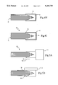
- FIG. 1 is a perspective view of a core sheet stock of a thermally conductive fiber composite material
- FIG. 2 is a perspective view of the core sheet stock with filler holes drilled in the ends thereof;
- FIG. 3 is a perspective view of the core sheet stock following machining of the core ends to a tapered edge
- FIGS. 4A-4I are cross-sectional views illustrating the fabrication steps of the tapered thermal substrate of the present invention.
- FIGS. 5A-5F are cross-sectional views illustrating several different embodiments of the tapered thermal substrate of the present invention fabricated substantially in accordance with steps illustrated in FIGS. 4A-4I.
- a stock fiber composite core 10 comprised of a plurality of parallel layers 12 of thermally conductive "pitch" type fibers in a matrix material (not shown).
- the fiber layers 12 of the stock core 10 may comprise P100, P120 or K1100 THORNEL graphite fibers (manufactured by the Amoco Advanced Composites Corporation) and the matrix material may comprise an epoxy resin. It will, of course, be understood that any equivalently performing thermally conductive fiber or matrix material may be used for the composite sheet stock core 10.
- the fibers within each layer 12 are substantially oriented in a single direction (generally indicated by arrow 14) extending between a first end (or edge) 16 and a second end (or edge) 18 that correspond to a thermal input and/or thermal output location.
- the core 10 further includes a top and bottom surface, 20 and 22, respectively, and opposed side edges 24 and 26.
- the thermal conductivity of the core 10 is high in the direction of the fibers (see arrow 14), but is low in directions transverse thereto (see directions indicated by the arrows 28 and 30 orthogonal to the direction 14).
- the fibers within some layers 12 of the composite core may be oriented in the direction indicated by arrow 30 or at any other selected angle between the zero degree angle of arrow 14 and the ninety degree angle of arrow 30.
- FIGS. 2 and 4B there is shown, in perspective and cross-sectional views, respectively, the fiber composite core 10 with a plurality of filler holes 32 drilled through the core from the top surface 20 to the bottom surface 22 adjacent the first end 16 and second end 18.
- the first end 16 and second end 18 of the core 10 are machined, preferably from both the top and bottom core surfaces, 20 and 22, respectively, to form a tapered edge 34 comprised of a top angled surface 36 and a bottom angled surface 38.
- the filler holes 32 function to distribute the forces generated on the core 10 during the step of machining the thermal substrate.
- the angled surfaces 36 and 38 expose the ends of the fibers of the layers 12 comprising the composite core 10 oriented in the direction of the arrow 14 to facilitate, in a manner to be described, the transfer of generated heat between the core and nearby heat sources or sinks. It will, of course, be understood that the machining of the core 10 may form as few as one or more than two angled surfaces (see FIG. 5D), as desired, without substantially affecting manufacturing cost or performance.
- a mask 40 is applied over the top and bottom surfaces, 20 and 22, respectively, leaving only the top angled surface 36 and bottom angled surface 38 exposed.
- a copper conductor is plated (deposited) over the core 10 and attached to the angled surfaces 36 and 38 to form a thermal tab 42 in thermal connection with the fiber ends.
- the filler holes 32 are filled with the plated copper and function as anchors securing the physical connection of the thermal tab 42 to the core 10.
- the mask 40 is then removed as shown in FIG. 4F and the attached thermal tab 42 is machined to a desired shape and thickness as shown in FIG. 4G for facilitating a thermal connection with the nearby heat sink or source.
- the core 10 and thermal tab 42 are then flashed with thin coatings of copper 46 and nickel 48 to complete fabrication of the tapered thermal substrate 50 of the present invention.
- the copper and nickel flashed coatings, 46 and 48 are shown exaggerated in size in FIGS. 4H and 4I and function to provide an environmental seal for the thermal substrate 50.
- FIGS. 5A-5F there are shown several cross-sectional views illustrating different configurations of the tapered thermal substrate 50 of the present invention. It will, of course, be understood these examples are by way of illustration and not limitation.
- a heat source or sink
- FIGS. 5A and 5B two adjacent positioning locations for a heat source (or sink) 52 are shown for the configuration of the tapered thermal substrate 50 shown in FIG. 4I.
- the generated heat is transferred, for example, by the fibers 12 from the heat source 52 in the direction shown by the arrow 54.
- the heat source 52 may also be positioned, in the manner illustrated by FIG. 5C, between the first and second ends, 16 and 18, respectively, of the core 10, adjacent an interior thermal tab 56 that is plated in a channel 58 machined in the top surface 20.
- the interior thermal tab 56 is machined to the size and shape required for thermal connection with the heat source 52.
- a heat sink 60 is shown positioned adjacent the edge thermal tabs 42 plated to the first and second ends of the core 10 to dissipate the heat transferred (in the direction shown by the arrow 54) from the heat source 52 by the tapered thermal substrate 50.
- the end of the core 10 (or any other core position) may be tapered to an edge having only a single angled surface 62, or more than two surfaces 64, in the manner illustrated by FIG. 5D.
- the position of the thermal tabs for thermal input and thermal output need not be at edges of the core 10, but may both be internal, as shown in FIG. 5E, if required by the application.
- the angled surface may alternatively comprise surface 66 having a curved shape to form the tapered edge as shown in FIG. 5F.
Abstract
Description
Claims (16)
Priority Applications (1)
| Application Number | Priority Date | Filing Date | Title |
|---|---|---|---|
| US07/915,460 US5255738A (en) | 1992-07-16 | 1992-07-16 | Tapered thermal substrate for heat transfer applications and method for making same |
Applications Claiming Priority (1)
| Application Number | Priority Date | Filing Date | Title |
|---|---|---|---|
| US07/915,460 US5255738A (en) | 1992-07-16 | 1992-07-16 | Tapered thermal substrate for heat transfer applications and method for making same |
Publications (1)
| Publication Number | Publication Date |
|---|---|
| US5255738A true US5255738A (en) | 1993-10-26 |
Family
ID=25435782
Family Applications (1)
| Application Number | Title | Priority Date | Filing Date |
|---|---|---|---|
| US07/915,460 Expired - Lifetime US5255738A (en) | 1992-07-16 | 1992-07-16 | Tapered thermal substrate for heat transfer applications and method for making same |
Country Status (1)
| Country | Link |
|---|---|
| US (1) | US5255738A (en) |
Cited By (33)
| Publication number | Priority date | Publication date | Assignee | Title |
|---|---|---|---|---|
| US5542471A (en) * | 1993-11-16 | 1996-08-06 | Loral Vought System Corporation | Heat transfer element having the thermally conductive fibers |
| US5695847A (en) * | 1996-07-10 | 1997-12-09 | Browne; James M. | Thermally conductive joining film |
| US5769158A (en) * | 1996-03-28 | 1998-06-23 | Mitsubishi Denki Kabushiki Kaisha | Interface portion structure and reinforcing structure of flexible thermal joint |
| US5812372A (en) * | 1996-06-07 | 1998-09-22 | International Business Machines Corporation | Tube in plate heat sink |
| US5826643A (en) * | 1996-06-07 | 1998-10-27 | International Business Machines Corporation | Method of cooling electronic devices using a tube in plate heat sink |
| US5962348A (en) * | 1998-03-05 | 1999-10-05 | Xc Associates | Method of making thermal core material and material so made |
| US5975201A (en) * | 1994-10-31 | 1999-11-02 | The Johns Hopkins University | Heat sink for increasing through-thickness thermal conductivity of organic matrix composite structures |
| US6075287A (en) * | 1997-04-03 | 2000-06-13 | International Business Machines Corporation | Integrated, multi-chip, thermally conductive packaging device and methodology |
| US6257328B1 (en) * | 1997-10-14 | 2001-07-10 | Matsushita Electric Industrial Co., Ltd. | Thermal conductive unit and thermal connection structure using the same |
| WO2001067019A1 (en) * | 2000-03-08 | 2001-09-13 | Thermal Corp. | Matrix heat sink with extending fibers |
| US6311769B1 (en) * | 1999-11-08 | 2001-11-06 | Space Systems/Loral, Inc. | Thermal interface materials using thermally conductive fiber and polymer matrix materials |
| US6378311B1 (en) | 2000-05-18 | 2002-04-30 | Raytheon Company | Thermoelectric dehumidifier |
| US20030116312A1 (en) * | 2001-12-13 | 2003-06-26 | Krassowski Daniel W. | Heat dissipating component using high conducting inserts |
| US20030230400A1 (en) * | 2002-06-13 | 2003-12-18 | Mccordic Craig H. | Cold plate assembly |
| EP1399612A1 (en) * | 2001-04-30 | 2004-03-24 | Thermo Composite, LLC | Thermal management material, devices and methods therefor |
| US20040188063A1 (en) * | 2003-03-31 | 2004-09-30 | Hung Chang | Heat dissipating device |
| US20050128709A1 (en) * | 2003-12-11 | 2005-06-16 | Norio Fujiwara | Heat-radiating structure of electronic apparatus |
| US20060109628A1 (en) * | 2004-11-19 | 2006-05-25 | Searby Tom J | Cooling apparatus for electronic devices |
| US20070102142A1 (en) * | 2005-11-04 | 2007-05-10 | Reis Bradley E | Heat spreaders with vias |
| US20070103875A1 (en) * | 2005-11-04 | 2007-05-10 | Reis Bradley E | Cycling LED Heat Spreader |
| US20070139895A1 (en) * | 2005-11-04 | 2007-06-21 | Reis Bradley E | LED with integral thermal via |
| US20100018953A1 (en) * | 2008-07-23 | 2010-01-28 | Vladimir Shapovalov | Reusable mandrel for solid free form fabrication process |
| US20110014417A1 (en) * | 2009-07-14 | 2011-01-20 | Lemak Richard J | Anisotropic thermal conduction element and manufacturing method |
| US7889502B1 (en) | 2005-11-04 | 2011-02-15 | Graftech International Holdings Inc. | Heat spreading circuit assembly |
| EP2562807A1 (en) * | 2011-08-22 | 2013-02-27 | ABB Research Ltd | Heat transfer in an electronic device |
| US20160373154A1 (en) * | 2015-06-16 | 2016-12-22 | Ii-Vi Incorporated | Electronic Device Housing Utilizing A Metal Matrix Composite |
| US20170089650A1 (en) * | 2015-09-24 | 2017-03-30 | Jones Tech (USA), Inc. | Flexible heat transfer structure |
| CN109413938A (en) * | 2018-10-24 | 2019-03-01 | 航天材料及工艺研究所 | A kind of efficient cooling means of composite material light and device |
| WO2019129896A1 (en) * | 2017-12-29 | 2019-07-04 | Airbus Defence And Space Sa | High-conductance thermal connector |
| US10392548B2 (en) * | 2013-07-23 | 2019-08-27 | Safran | Composite material part having a thermally and electrically conductive portion, and a method of fabricating such a part |
| US20200191497A1 (en) * | 2018-10-24 | 2020-06-18 | Roccor, Llc | Deployable Radiator Devices, Systems, and Methods Utilizing Composite Laminates |
| US11248852B2 (en) * | 2020-07-06 | 2022-02-15 | Dell Products L.P. | Graphite thermal cable and method for implementing same |
| US20230200019A1 (en) * | 2021-12-20 | 2023-06-22 | Meta Platforms Technologies, Llc | Thermal conduit for electronic device |
Citations (14)
| Publication number | Priority date | Publication date | Assignee | Title |
|---|---|---|---|---|
| US3543842A (en) * | 1966-10-13 | 1970-12-01 | Bolkow Gmbh | Device for elastic and heat conducting connection of thermo-couples |
| US3913666A (en) * | 1972-03-20 | 1975-10-21 | Peter Bayliss | Heat resistant wall construction |
| US4278707A (en) * | 1980-05-19 | 1981-07-14 | Hewlett-Packard Company | Method for coating the edge of a printed circuit board to improve its moisture resistance |
| US4689110A (en) * | 1983-12-22 | 1987-08-25 | Trw Inc. | Method of fabricating multilayer printed circuit board structure |
| US4849858A (en) * | 1986-10-20 | 1989-07-18 | Westinghouse Electric Corp. | Composite heat transfer means |
| US4867235A (en) * | 1986-10-20 | 1989-09-19 | Westinghouse Electric Corp. | Composite heat transfer means |
| US4878152A (en) * | 1987-06-16 | 1989-10-31 | Thomson-Csf | Mounting for printed circuits forming a heat sink with controlled expansion |
| US4963414A (en) * | 1989-06-12 | 1990-10-16 | General Electric Company | Low thermal expansion, heat sinking substrate for electronic surface mount applications |
| US4966226A (en) * | 1989-12-29 | 1990-10-30 | Digital Equipment Corporation | Composite graphite heat pipe apparatus and method |
| US4987425A (en) * | 1987-11-13 | 1991-01-22 | Dornier System Gmbh | Antenna support structure |
| US5039577A (en) * | 1990-05-31 | 1991-08-13 | Hughes Aircraft Company | Hybrid metal matrix composite chassis structure for electronic circuits |
| US5077637A (en) * | 1989-09-25 | 1991-12-31 | The Charles Stark Draper Lab., Inc. | Solid state directional thermal cable |
| US5111359A (en) * | 1991-04-17 | 1992-05-05 | E-Systems Inc. | Heat transfer device and method |
| US5113315A (en) * | 1990-08-07 | 1992-05-12 | Cirqon Technologies Corporation | Heat-conductive metal ceramic composite material panel system for improved heat dissipation |
-
1992
- 1992-07-16 US US07/915,460 patent/US5255738A/en not_active Expired - Lifetime
Patent Citations (14)
| Publication number | Priority date | Publication date | Assignee | Title |
|---|---|---|---|---|
| US3543842A (en) * | 1966-10-13 | 1970-12-01 | Bolkow Gmbh | Device for elastic and heat conducting connection of thermo-couples |
| US3913666A (en) * | 1972-03-20 | 1975-10-21 | Peter Bayliss | Heat resistant wall construction |
| US4278707A (en) * | 1980-05-19 | 1981-07-14 | Hewlett-Packard Company | Method for coating the edge of a printed circuit board to improve its moisture resistance |
| US4689110A (en) * | 1983-12-22 | 1987-08-25 | Trw Inc. | Method of fabricating multilayer printed circuit board structure |
| US4849858A (en) * | 1986-10-20 | 1989-07-18 | Westinghouse Electric Corp. | Composite heat transfer means |
| US4867235A (en) * | 1986-10-20 | 1989-09-19 | Westinghouse Electric Corp. | Composite heat transfer means |
| US4878152A (en) * | 1987-06-16 | 1989-10-31 | Thomson-Csf | Mounting for printed circuits forming a heat sink with controlled expansion |
| US4987425A (en) * | 1987-11-13 | 1991-01-22 | Dornier System Gmbh | Antenna support structure |
| US4963414A (en) * | 1989-06-12 | 1990-10-16 | General Electric Company | Low thermal expansion, heat sinking substrate for electronic surface mount applications |
| US5077637A (en) * | 1989-09-25 | 1991-12-31 | The Charles Stark Draper Lab., Inc. | Solid state directional thermal cable |
| US4966226A (en) * | 1989-12-29 | 1990-10-30 | Digital Equipment Corporation | Composite graphite heat pipe apparatus and method |
| US5039577A (en) * | 1990-05-31 | 1991-08-13 | Hughes Aircraft Company | Hybrid metal matrix composite chassis structure for electronic circuits |
| US5113315A (en) * | 1990-08-07 | 1992-05-12 | Cirqon Technologies Corporation | Heat-conductive metal ceramic composite material panel system for improved heat dissipation |
| US5111359A (en) * | 1991-04-17 | 1992-05-05 | E-Systems Inc. | Heat transfer device and method |
Cited By (54)
| Publication number | Priority date | Publication date | Assignee | Title |
|---|---|---|---|---|
| US5542471A (en) * | 1993-11-16 | 1996-08-06 | Loral Vought System Corporation | Heat transfer element having the thermally conductive fibers |
| US5975201A (en) * | 1994-10-31 | 1999-11-02 | The Johns Hopkins University | Heat sink for increasing through-thickness thermal conductivity of organic matrix composite structures |
| US5769158A (en) * | 1996-03-28 | 1998-06-23 | Mitsubishi Denki Kabushiki Kaisha | Interface portion structure and reinforcing structure of flexible thermal joint |
| US5812372A (en) * | 1996-06-07 | 1998-09-22 | International Business Machines Corporation | Tube in plate heat sink |
| US5826643A (en) * | 1996-06-07 | 1998-10-27 | International Business Machines Corporation | Method of cooling electronic devices using a tube in plate heat sink |
| US6173759B1 (en) | 1996-06-07 | 2001-01-16 | International Business Machines Corporation | Method of cooling electronic devices using a tube in plate heat sink |
| US5695847A (en) * | 1996-07-10 | 1997-12-09 | Browne; James M. | Thermally conductive joining film |
| US5849130A (en) * | 1996-07-10 | 1998-12-15 | Browne; James M. | Method of making and using thermally conductive joining film |
| US6014999A (en) * | 1996-07-10 | 2000-01-18 | Browne; James M. | Apparatus for making thermally conductive film |
| US6075287A (en) * | 1997-04-03 | 2000-06-13 | International Business Machines Corporation | Integrated, multi-chip, thermally conductive packaging device and methodology |
| US6257328B1 (en) * | 1997-10-14 | 2001-07-10 | Matsushita Electric Industrial Co., Ltd. | Thermal conductive unit and thermal connection structure using the same |
| US5962348A (en) * | 1998-03-05 | 1999-10-05 | Xc Associates | Method of making thermal core material and material so made |
| US6311769B1 (en) * | 1999-11-08 | 2001-11-06 | Space Systems/Loral, Inc. | Thermal interface materials using thermally conductive fiber and polymer matrix materials |
| WO2001067019A1 (en) * | 2000-03-08 | 2001-09-13 | Thermal Corp. | Matrix heat sink with extending fibers |
| US6378311B1 (en) | 2000-05-18 | 2002-04-30 | Raytheon Company | Thermoelectric dehumidifier |
| EP1399612A1 (en) * | 2001-04-30 | 2004-03-24 | Thermo Composite, LLC | Thermal management material, devices and methods therefor |
| EP1399612A4 (en) * | 2001-04-30 | 2008-04-30 | Thermo Composite Llc | Thermal management material, devices and methods therefor |
| US6758263B2 (en) * | 2001-12-13 | 2004-07-06 | Advanced Energy Technology Inc. | Heat dissipating component using high conducting inserts |
| US20030116312A1 (en) * | 2001-12-13 | 2003-06-26 | Krassowski Daniel W. | Heat dissipating component using high conducting inserts |
| US20030230400A1 (en) * | 2002-06-13 | 2003-12-18 | Mccordic Craig H. | Cold plate assembly |
| US6903931B2 (en) * | 2002-06-13 | 2005-06-07 | Raytheon Company | Cold plate assembly |
| US7111667B2 (en) * | 2003-03-31 | 2006-09-26 | Micro-Star Int'l Co., Ltd. | Heat dissipating device |
| US20040188063A1 (en) * | 2003-03-31 | 2004-09-30 | Hung Chang | Heat dissipating device |
| US20050128709A1 (en) * | 2003-12-11 | 2005-06-16 | Norio Fujiwara | Heat-radiating structure of electronic apparatus |
| US7280359B2 (en) * | 2003-12-11 | 2007-10-09 | Matsushita Electric Industrial Co., Ltd. | Heat-radiating structure of electronic apparatus |
| US20090073660A1 (en) * | 2004-11-19 | 2009-03-19 | Hewlett-Packard Development Company, L.P. | Cooling apparatus for electronic devices |
| US20060109628A1 (en) * | 2004-11-19 | 2006-05-25 | Searby Tom J | Cooling apparatus for electronic devices |
| US7443683B2 (en) | 2004-11-19 | 2008-10-28 | Hewlett-Packard Development Company, L.P. | Cooling apparatus for electronic devices |
| US20070103875A1 (en) * | 2005-11-04 | 2007-05-10 | Reis Bradley E | Cycling LED Heat Spreader |
| US7889502B1 (en) | 2005-11-04 | 2011-02-15 | Graftech International Holdings Inc. | Heat spreading circuit assembly |
| US7303005B2 (en) | 2005-11-04 | 2007-12-04 | Graftech International Holdings Inc. | Heat spreaders with vias |
| US20070139895A1 (en) * | 2005-11-04 | 2007-06-21 | Reis Bradley E | LED with integral thermal via |
| US7505275B2 (en) | 2005-11-04 | 2009-03-17 | Graftech International Holdings Inc. | LED with integral via |
| US20070102142A1 (en) * | 2005-11-04 | 2007-05-10 | Reis Bradley E | Heat spreaders with vias |
| US7573717B2 (en) | 2005-11-04 | 2009-08-11 | Graftech International Holdings Inc. | Cycling LED heat spreader |
| US7365988B2 (en) | 2005-11-04 | 2008-04-29 | Graftech International Holdings Inc. | Cycling LED heat spreader |
| EP2300182A4 (en) * | 2008-07-23 | 2012-01-04 | Materials & Electrochemical Res Corp | Reusable mandrel for solid free form fabrication process |
| WO2010011564A1 (en) * | 2008-07-23 | 2010-01-28 | Materials & Electrochemical Research Corp. | Reusable mandrel for solid free form fabrication process |
| EP2300182A1 (en) * | 2008-07-23 | 2011-03-30 | Materials & Electrochemical Research Corp. | Reusable mandrel for solid free form fabrication process |
| US20100018953A1 (en) * | 2008-07-23 | 2010-01-28 | Vladimir Shapovalov | Reusable mandrel for solid free form fabrication process |
| US8085531B2 (en) * | 2009-07-14 | 2011-12-27 | Specialty Minerals (Michigan) Inc. | Anisotropic thermal conduction element and manufacturing method |
| EP2454551A4 (en) * | 2009-07-14 | 2016-09-28 | Specialty Minerals Michigan | Anisotropic thermal conduction element and manufacturing method |
| US20110014417A1 (en) * | 2009-07-14 | 2011-01-20 | Lemak Richard J | Anisotropic thermal conduction element and manufacturing method |
| EP2562807A1 (en) * | 2011-08-22 | 2013-02-27 | ABB Research Ltd | Heat transfer in an electronic device |
| US10392548B2 (en) * | 2013-07-23 | 2019-08-27 | Safran | Composite material part having a thermally and electrically conductive portion, and a method of fabricating such a part |
| US20160373154A1 (en) * | 2015-06-16 | 2016-12-22 | Ii-Vi Incorporated | Electronic Device Housing Utilizing A Metal Matrix Composite |
| US20170089650A1 (en) * | 2015-09-24 | 2017-03-30 | Jones Tech (USA), Inc. | Flexible heat transfer structure |
| WO2019129896A1 (en) * | 2017-12-29 | 2019-07-04 | Airbus Defence And Space Sa | High-conductance thermal connector |
| JP7133020B2 (en) | 2017-12-29 | 2022-09-07 | エアバス ディフェンス アンド スペース,エス.エー. | High conductance thermal link |
| US11521910B2 (en) * | 2017-12-29 | 2022-12-06 | Airbus Defence And Space Sa | High-conductance thermal connector |
| CN109413938A (en) * | 2018-10-24 | 2019-03-01 | 航天材料及工艺研究所 | A kind of efficient cooling means of composite material light and device |
| US20200191497A1 (en) * | 2018-10-24 | 2020-06-18 | Roccor, Llc | Deployable Radiator Devices, Systems, and Methods Utilizing Composite Laminates |
| US11248852B2 (en) * | 2020-07-06 | 2022-02-15 | Dell Products L.P. | Graphite thermal cable and method for implementing same |
| US20230200019A1 (en) * | 2021-12-20 | 2023-06-22 | Meta Platforms Technologies, Llc | Thermal conduit for electronic device |
Similar Documents
| Publication | Publication Date | Title |
|---|---|---|
| US5255738A (en) | Tapered thermal substrate for heat transfer applications and method for making same | |
| US3777220A (en) | Circuit panel and method of construction | |
| EP0147014B1 (en) | Multilayer printed circuit board structure | |
| US5499444A (en) | Method of manufacturing a rigid flex printed circuit board | |
| US4849858A (en) | Composite heat transfer means | |
| US4882454A (en) | Thermal interface for a printed wiring board | |
| US4687695A (en) | Flexible printed circuits and methods of fabricating and forming plated thru-holes therein | |
| US4867235A (en) | Composite heat transfer means | |
| US7303639B2 (en) | Method for producing Z-axis interconnection assembly of printed wiring board elements | |
| US5419038A (en) | Method for fabricating thin-film interconnector | |
| US7420127B2 (en) | Method of manufacturing multilayer wiring substrate, and multilayer wiring substrate | |
| US4963697A (en) | Advanced polymers on metal printed wiring board | |
| US6222740B1 (en) | Multilayer circuit board having at least one core substrate arranged therein | |
| US5216807A (en) | Method of producing electrical connection members | |
| EP1058490B1 (en) | Printed wiring board structure with integral organic matrix composite core | |
| US4255752A (en) | Lightweight composite slotted-waveguide antenna and method of manufacture | |
| US6820332B2 (en) | Laminate circuit structure and method of fabricating | |
| CA2030826C (en) | Composite circuit board with thick embedded conductor and method of manufacturing the same | |
| EP1058491B1 (en) | Printed wiring board structure with integral metal matrix composite core | |
| US10542625B2 (en) | Wiring substrate | |
| US5975201A (en) | Heat sink for increasing through-thickness thermal conductivity of organic matrix composite structures | |
| EP1025586B1 (en) | Flexible heat transfer device and method | |
| EP1627427A2 (en) | An encased thermal management device and method of making such a device | |
| US5002715A (en) | Method for the fabrication of a heat transfer member for electronic systems | |
| US4662963A (en) | Method of manufacturing high density encapsulated wire circuit board |
Legal Events
| Date | Code | Title | Description |
|---|---|---|---|
| AS | Assignment |
Owner name: E-SYSTEMS, INC., TEXAS Free format text: ASSIGNMENT OF ASSIGNORS INTEREST.;ASSIGNOR:PRZILAS, MARK B.;REEL/FRAME:006218/0687 Effective date: 19920715 |
|
| STCF | Information on status: patent grant |
Free format text: PATENTED CASE |
|
| FPAY | Fee payment |
Year of fee payment: 4 |
|
| AS | Assignment |
Owner name: RAYTHEON E-SYSTEMS, INC., A CORP. OF DELAWARE, TEX Free format text: CHANGE OF NAME;ASSIGNOR:E-SYSTEMS, INC.;REEL/FRAME:009507/0603 Effective date: 19960703 |
|
| AS | Assignment |
Owner name: RAYTHEON COMPANY, A CORP. OF DELAWARE, MASSACHUSET Free format text: ASSIGNMENT OF ASSIGNORS INTEREST;ASSIGNOR:RAYTHEON E-SYSTEMS, INC., A CORP. OF DELAWARE;REEL/FRAME:009570/0001 Effective date: 19981030 |
|
| FEPP | Fee payment procedure |
Free format text: PAYOR NUMBER ASSIGNED (ORIGINAL EVENT CODE: ASPN); ENTITY STATUS OF PATENT OWNER: LARGE ENTITY |
|
| FPAY | Fee payment |
Year of fee payment: 8 |
|
| AS | Assignment |
Owner name: L-3 COMMUNICATIONS INTEGRATED SYSTEMS L.P., NEW YO Free format text: ASSIGNMENT OF ASSIGNORS INTEREST;ASSIGNOR:RAYTHEON COMPANY;REEL/FRAME:013067/0432 Effective date: 20020606 |
|
| REMI | Maintenance fee reminder mailed | ||
| FPAY | Fee payment |
Year of fee payment: 12 |
|
| SULP | Surcharge for late payment |
Year of fee payment: 11 |