US5247243A - Method and apparatus for conducting electrochemiluminescent measurements - Google Patents
Method and apparatus for conducting electrochemiluminescent measurements Download PDFInfo
- Publication number
- US5247243A US5247243A US07/744,890 US74489091A US5247243A US 5247243 A US5247243 A US 5247243A US 74489091 A US74489091 A US 74489091A US 5247243 A US5247243 A US 5247243A
- Authority
- US
- United States
- Prior art keywords
- waveform
- sample
- working electrode
- voltage waveform
- electrochemiluminescence
- Prior art date
- Legal status (The legal status is an assumption and is not a legal conclusion. Google has not performed a legal analysis and makes no representation as to the accuracy of the status listed.)
- Expired - Lifetime
Links
- 238000000034 method Methods 0.000 title claims abstract description 24
- 238000005259 measurement Methods 0.000 title abstract description 26
- 230000001960 triggered effect Effects 0.000 claims abstract description 7
- 230000004044 response Effects 0.000 claims description 8
- 230000002194 synthesizing effect Effects 0.000 claims description 6
- 238000001514 detection method Methods 0.000 claims description 4
- 230000005855 radiation Effects 0.000 claims 3
- 238000005401 electroluminescence Methods 0.000 claims 1
- 230000003247 decreasing effect Effects 0.000 abstract 1
- 210000004188 enterochromaffin-like cell Anatomy 0.000 description 23
- 239000000523 sample Substances 0.000 description 23
- 239000012491 analyte Substances 0.000 description 6
- 210000004027 cell Anatomy 0.000 description 6
- 238000010586 diagram Methods 0.000 description 6
- 230000005518 electrochemistry Effects 0.000 description 6
- 230000004048 modification Effects 0.000 description 6
- 238000012986 modification Methods 0.000 description 6
- 239000012488 sample solution Substances 0.000 description 6
- 239000000126 substance Substances 0.000 description 5
- 239000000203 mixture Substances 0.000 description 4
- 238000006243 chemical reaction Methods 0.000 description 3
- 230000007423 decrease Effects 0.000 description 3
- 230000008901 benefit Effects 0.000 description 2
- 238000004140 cleaning Methods 0.000 description 2
- 230000003750 conditioning effect Effects 0.000 description 2
- 239000000376 reactant Substances 0.000 description 2
- 229910001220 stainless steel Inorganic materials 0.000 description 2
- 239000010935 stainless steel Substances 0.000 description 2
- 230000002411 adverse Effects 0.000 description 1
- 238000003556 assay Methods 0.000 description 1
- 230000001276 controlling effect Effects 0.000 description 1
- 230000002596 correlated effect Effects 0.000 description 1
- 230000000875 corresponding effect Effects 0.000 description 1
- 230000000694 effects Effects 0.000 description 1
- 230000005684 electric field Effects 0.000 description 1
- 230000005611 electricity Effects 0.000 description 1
- 230000006872 improvement Effects 0.000 description 1
- 238000000691 measurement method Methods 0.000 description 1
- 239000007800 oxidant agent Substances 0.000 description 1
- 230000001590 oxidative effect Effects 0.000 description 1
- 230000002572 peristaltic effect Effects 0.000 description 1
- 230000008569 process Effects 0.000 description 1
- 238000006479 redox reaction Methods 0.000 description 1
Images

Classifications
-
- H—ELECTRICITY
- H03—ELECTRONIC CIRCUITRY
- H03K—PULSE TECHNIQUE
- H03K4/00—Generating pulses having essentially a finite slope or stepped portions
- H03K4/02—Generating pulses having essentially a finite slope or stepped portions having stepped portions, e.g. staircase waveform
- H03K4/026—Generating pulses having essentially a finite slope or stepped portions having stepped portions, e.g. staircase waveform using digital techniques
-
- G—PHYSICS
- G01—MEASURING; TESTING
- G01N—INVESTIGATING OR ANALYSING MATERIALS BY DETERMINING THEIR CHEMICAL OR PHYSICAL PROPERTIES
- G01N21/00—Investigating or analysing materials by the use of optical means, i.e. using sub-millimetre waves, infrared, visible or ultraviolet light
- G01N21/62—Systems in which the material investigated is excited whereby it emits light or causes a change in wavelength of the incident light
- G01N21/66—Systems in which the material investigated is excited whereby it emits light or causes a change in wavelength of the incident light electrically excited, e.g. electroluminescence
-
- G—PHYSICS
- G01—MEASURING; TESTING
- G01N—INVESTIGATING OR ANALYSING MATERIALS BY DETERMINING THEIR CHEMICAL OR PHYSICAL PROPERTIES
- G01N27/00—Investigating or analysing materials by the use of electric, electrochemical, or magnetic means
- G01N27/26—Investigating or analysing materials by the use of electric, electrochemical, or magnetic means by investigating electrochemical variables; by using electrolysis or electrophoresis
- G01N27/416—Systems
- G01N27/48—Systems using polarography, i.e. measuring changes in current under a slowly-varying voltage
Definitions
- This invention relates to electrochemiluminescent phenomena and more particularly to a system and method for detecting and measuring electrochemiluminescent phenomena.
- ECL electrochemiluminescence
- EC electrochemistry
- CL chemiluminescence
- CL based assay or detection techniques generally comprise forming a mixture of a sample containing an unknown amount of an analyte of interest with a known amount of a reactant which is conjugated with a chemiluminescent label. The mixture is incubated to allow the labeled reactant to bind to the analyte and then is separated into a bound and an unbound fraction. One or both fractions are caused to luminesce by, for example, the addition of an oxidant to the fractions. The measured level of chemiluminescence at a specific wavelength is indicative of the amount of the bound or unbound fraction, and one skilled in the art can determine from such measurements the amount of analyte in the sample.
- ECL detection techniques provide a sensitive and controllable measurement of the presence and amount of an analyte of interest.
- the incubated sample is exposed to a voltammetric working electrode, i.e., an electrode to which a voltage is applied and into which a current for a redox reaction is passed.
- the ECL mixture does not react with the chemical environment alone, as does the CL mixture, or with an electric field alone, as in EC, but rather electrochemiluminescence is triggered by a voltage impressed on the working electrode at a particular time and in a particular manner to controllably cause the ECL sample to emit light at the electrochemiluminescent wavelength of interest.
- the measurement is not the current at the electrode, as in EC, but the frequency and intensity of emitted light.
- the voltage waveform impressed upon the voltammetric electrode of an ECL cell must be sufficient to trigger electrochemiluminescence.
- This voltage waveform usually is in the form of a uniform voltage sweep starting at a first voltage, moving steadily to a second voltage, moving back through the first voltage to a third voltage and then back again to the first voltage.
- Other waveforms have been applied in practice, however, and can trigger ECL.
- the ECL measurement In order to be meaningful, the ECL measurement must be precise, i.e., repeatable within strict limits with the same operating conditions and ECL sample. The measurement also must be accurate, i.e., within acceptable limits of the actual concentration of analyte present in the sample. Since the ECL reaction chemically changes the sample, only one ECL measurement generally can be taken for each sample. These chemical changes occur predominantly within a thin layer of the sample adjacent the working electrode.
- the uniform scanning voltage waveform applied to the working electrode of an ECL cell to trigger electrochemiluminescence is modified such that the precision and accuracy of ECL measurements are improved.
- This modified waveform is substantially sinusoidal in shape at the voltages where ECL is triggered. This modification advantageously causes the ECL reaction to slow and occur more uniformally and consistently and enables ECL measurements to be made more precisely and accurately.
- a conventional electrochemical or ECL cell comprises a working electrode, a counter electrode and a reference electrode, and the voltage waveform for triggering electrochemiluminescence is applied to the working electrode using a potentiostat.
- the potentiostat applies a controlled voltage waveform at the reference electrode, with respect to the working electrode, and the working electrode is maintained at virtual ground.
- the reference electrode is placed in close potential proximity to the working electrode.
- the reference electrode of the ECL cell is placed in close potential proximity to the counter electrode, and a controlled voltage waveform is applied at the reference electrode.
- This placement diminishes the extent to which the waveform applied at the working electrode can be controlled.
- this waveform becomes modified at its operative point adjacent the working electrode.
- the amount of modification is substantially proportional to the resistance of the solution in the cell and the current passing between the counter and working electrodes. The present inventors have found that although the solution resistance remains substantially constant throughout an ECL event, the current in the cell increases near the voltage where light is emitted.
- the controlled voltage waveform has a uniform scan rate
- the waveform occurring at the working electrode decreases in scan rate and is found to become substantially sinusoidal in shape around the voltage at which ECL occurs.
- This modified waveform occurring at the working electrode although subject to less control by the potentiostat, advantageously results in more precise and accurate ECL measurements.
- This invention also comprises in another aspect synthesizing the modified waveform occurring at the working electrode, when the reference electrode is adjacent the counter electrode, and then applying this synthesized waveform directly to the working electrode with the reference electrode adjacent the working electrode for more precise control. With the reference electrode in the latter position, the operative waveform applied to the working electrode can be accurately controlled and closely monitored by the potentiostat.
- this modified waveform can be calculated from a measure of the current flowing in the ECL cell during an ECL event.
- a computer or microprocessor can be used advantageously to perform this calculation and to synthesize the modified waveform digitally, and the digitally synthesized waveform can be converted to an analog waveform using a digital to analog converter.
- the synthesized analog waveform then can be applied precisely to the working electrode using a potentiostat with the reference electrode in close potential proximity to the working electrode. This method has the further advantage that small changes can be made to the synthesized waveform and accurately evaluated for further improvement in the ECL response and measurement.
- this invention provides apparatus for applying a modified scanning voltage waveform to the working electrode of an ECL cell.
- This apparatus preferably comprises a potentiostat with its reference electrode in close potential proximity to its working electrode, and the modified waveform preferably is substantially a function of the current induced in the ECL cell during the triggering of electrochemiluminescence.
- the apparatus first synthesizes the modified waveform digitally, converts the digital waveform to an analog waveform and then applies the analog waveform to the working electrode using the potentiostat with its reference electrode in close potential proximity to the working electrode.
- This invention also provides in another aspect a method for measuring electrochemiluminescent phenomena by applying a modified scanning voltage waveform to the working electrode of an ECL cell to trigger electrochemiluminescence with the modified voltage waveform being substantially a function of the current induced in the ECL cell during electrochemiluminescence.
- the modified voltage waveform preferably is the result of a uniform scanning voltage waveform (triangular waveform) minus a second waveform having a magnitude substantially a function of the current induced in the ECL cell.
- this method further comprises synthesizing the modified voltage waveform digitally, converting the digital waveform to an analog waveform using an analog to digital converter and then applying the analog waveform to the working electrode of an ECL cell.
- FIG. 1 is a front view of an apparatus according to the present invention
- FIG. 2 is a block diagram of voltage control apparatus for controlling the voltages applied to the apparatus of FIG. 1;
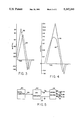
- FIG. 3 is a waveform diagram illustrating voltages applied to the apparatus of FIG. 1;
- FIG. 4 is a waveform diagram illustrating voltages, modified in accordance with the present invention, for application to the apparatus of FIG. 1;
- FIG. 5 is a block diagram of voltage control apparatus for synthesizing and applying the voltages illustrated in FIG. 4 to the apparatus of FIG. 1.
- FIG. 1 shows an ECL measuring apparatus 10 for applying the present invention.
- Apparatus 10 is a flow-through type ECL measuring apparatus, but, as is apparent from the following description, this invention is not limited to flow-through type ECL measuring apparatus and may be employed advantageously in all types of ECL apparatus utilizing a working electrode or other triggering surface to provide electrochemical energy to trigger an analyte of interest into electrochemiluminescence.
- Apparatus 10 comprises an ECL cell 12, mounted on supporting structure 42, enclosed within light-tight drawer 14 which is removably mounted within a larger instrument for conducting ECL measurements.
- This instrument also includes detecting and measuring apparatus (not shown) for detecting and measuring the light emitted from a sample within the ECL cell 12 during ECL.
- the detecting and measuring apparatus advantageously may be a photomultiplier tube, photodiode, charge coupled device, photographic film or the like.
- suitable detecting and measuring apparatus reference is made to U.S. Pat. Nos. 5,147,806 and 5,093,268, assigned in common with the present application.
- Intake tubing 22 which may be constructed advantageously of stainless steel, passes through drawer 14 into a container (not shown) holding a solution to be sampled.
- a pump also not shown, which is advantageously a peristaltic pump, at the end of exit tubing 24 causes a sample of this solution to pass through the intake tubing 22 into the sample holding volume 44 of the ECL cell. Electrochemiluminescence is triggered within the cell by working electrode 18 and counter electrode 16 and is measured by the detecting and measuring apparatus. After the measurement, the sample is pumped out of the holding volume 44, through exit tubing 24 (also advantageously constructed of stainless steel), and through the reference electrode holding volume 46. This process is repeated for each sample to be tested.
- Reference electrode 20 is incorporated within exit tubing 24 and enclosed within housing 28. In this position, this electrode is exposed to substantially the same voltage potential within the solution in sample holding volume 44 as that to which the counter electrode 16 is exposed. If housing 28 and reference electrode 20 were incorporated within the intake tubing 22, rather than the exit tubing 24, the reference electrode would be exposed to substantially the same voltage potential within the sample solution as that to which the working electrode 18 is exposed. The latter position is that generally used in a conventional electrochemical cell.
- Connectors 32, 34 and 36 connect the reference electrode 20, working electrode 18 and counter electrode 16, respectively, to terminal connectors 30 which are connected to the voltage control circuit 60 shown in FIG. 2.
- Male connectors 38 and 40 are removably inserted into female connectors within supporting structure 42 to enable the ECL cell to be electrically disassociated from the voltage control circuit and the working and counter electrodes to be reversed in function if desired.
- Voltage control circuit 60 advantageously operates in the manner of a potentiostat to supply a controlled voltage waveform at reference electrode 20 with respect to the working electrode 18.
- Connectors 62, 64 and 68 of voltage control 60 are connected to terminals 30 and then to connectors 34, 36 and 32, respectively, which are connected to the working electrode 18, counter electrode 16 and reference electrode 20, respectively, of ECL apparatus 10.
- An input voltage V in to voltage control 60 is provided on connector 70.
- Connector 62, connected to the working electrode 18, and input connector 72 are held at virtual ground.
- voltage control 60 forces the voltage appearing on connector 68, connected to the reference electrode 20, to duplicate V in appearing on input connector 70. No significant current flows through reference electrode 20, but this electrode provides a reference against which the voltage between the counter and working electrodes adjusts until the voltage at the reference electrode, with respect to the working electrode (i.e., ground), duplicates the voltage V in on connector 70.
- Potentiostats for this purpose are well known, and the internal structure of voltage control 60 may correspond to any of the conventional, commercially available potentiostats which operate in this manner.
- Reference electrode 20 senses a voltage potential within the sample solution substantially equivalent to that adjacent counter electrode 16. If reference electrode 20 were located within the intake tubing 22 above the working electrode 18 shown in FIG. 1, then the reference electrode would sense substantially the same potential within the solution as that adjacent working electrode 18. The same result could be achieved by reversing male connectors 38 and 40 which would in effect make electrode 16 the working electrode and electrode 18 the counter electrode.
- Locating the reference electrode at a voltage potential substantially equivalent to that adjacent the working electrode enables the voltage waveform applied to the working electrode to be precisely controlled and closely monitored. This position is conventional for electrochemical cells.
- FIG. 3 is a waveform diagram of voltages within ECL cell 12 during the triggering of ECL with the reference electrode 20 at a position for sensing the voltage substantially adjacent the working electrode (a position opposite to that shown in FIG. 1).
- Waveform 100 is the voltage applied at the reference electrode
- waveform 102 is the voltage measured within the solution by a probe substantially adjacent the counter electrode.
- the scan rate for the applied voltage 100 is 500 millivolts per second.
- FIG. 4 is a waveform diagram of voltages within ECL cell 12 during the triggering of ECL with the reference electrode 20 in the alternative position shown in FIG. 1 for sensing the voltage adjacent the counter electrode.
- Waveform 110 is the voltage applied at the reference electrode, which has a uniform scan rate of 500 millivolts per second
- waveform 112 is the voltage measured within the sample solution by a probe substantially adjacent the working electrode. Waveform 112 shows a decrease in the scan rate or a plateauing around the period that electrochemiluminescence occurs. The voltage measured adjacent the working electrode during this period is between 1.4 and 1.6 volts.
- the potentiostat keeps the applied voltage in the solution at the reference electrode adjacent the counter electrode, waveform 110, at the uniform, selected scan rate.
- FIG. 5 shows a second embodiment of apparatus for control of the voltages applied to the apparatus of FIG. 1.
- This second embodiment advantageously synthesizes the waveform digitally that is applied at the reference electrode, with respect to the working electrode, using digital computer 120.
- This digitally synthesized waveform advantageously is equivalent to waveform 112, the waveform resulting at the working electrode with the reference electrode in its alternative position adjacent the counter electrode, when the waveform applied at the reference electrode is a uniform scanning voltage waveform.
- This synthesized waveform is applied to ECL cell 12 with reference electrode 20 in its conventional position adjacent working electrode 18.
- the digital synthesization of the waveform also can be effected with a microprocessor, special purpose computer or similar digital device.
- the digitally synthesized waveform can be calculated from a measure of the current flowing in the ECL cell during ECL with the reference electrode in its alternative position adjacent the counter electrode. This current times the resistance of the sample solution defines a second waveform which is subtracted from the uniform scanning voltage waveform (triangular waveform) applied at the reference electrode to create the modified waveform.
- the digitally synthesized waveform is fed through data lines 126 to digital to analog converter 122 whose output on connector 128, with respect to that appearing on connector 130 which is held at virtual ground, is the corresponding synthesized waveform in analog form.
- the voltage appearing on connector 128 is the input voltage V in to voltage control 124 which, like voltage control 60, advantageously operates in the manner of a potentiostat to supply a controlled voltage waveform substantially identical to V in on connector 136 with respect to connector 132 (virtual ground).
- reference electrode 20 is located within the intake tubing 22 (opposite to the position shown in FIG. 1) for sensing the voltage potential within the sample solution substantially equivalent to that surrounding working electrode 18.
- Connectors 132, 134 and 136 of voltage control 124 are connected through terminals 30 to connectors 34, 36 and 32, respectively, and, therefore, to the working electrode 18, counter electrode 16 and reference electrode 20, respectively, of ECL apparatus 10.
- the applied scanning waveform is synthesized with its desirable plateau and substantially sinusoidial shape around the voltage for triggering ECL, and this waveform is precisely applied directly to the working electrode.
- This embodiment also enables minor modifications to be made in the synthesized waveform, and the degree to which they improve or adversely affect ECL response and measurements, to be directly correlated.
Abstract
Description
Claims (9)
Priority Applications (2)
| Application Number | Priority Date | Filing Date | Title |
|---|---|---|---|
| US07/744,890 US5247243A (en) | 1988-11-03 | 1991-08-14 | Method and apparatus for conducting electrochemiluminescent measurements |
| US08/057,682 US5296191A (en) | 1988-11-03 | 1993-05-04 | Method and apparatus for conducting electrochemiluminescent measurements |
Applications Claiming Priority (3)
| Application Number | Priority Date | Filing Date | Title |
|---|---|---|---|
| US07/267,234 US5061445A (en) | 1988-11-03 | 1988-11-03 | Apparatus for conducting measurements of electrochemiluminescent phenomena |
| US07/325,459 US5068088A (en) | 1988-11-03 | 1989-03-17 | Method and apparatus for conducting electrochemiluminescent measurements |
| US07/744,890 US5247243A (en) | 1988-11-03 | 1991-08-14 | Method and apparatus for conducting electrochemiluminescent measurements |
Related Parent Applications (1)
| Application Number | Title | Priority Date | Filing Date |
|---|---|---|---|
| US07/325,459 Continuation US5068088A (en) | 1988-11-03 | 1989-03-17 | Method and apparatus for conducting electrochemiluminescent measurements |
Related Child Applications (1)
| Application Number | Title | Priority Date | Filing Date |
|---|---|---|---|
| US08/057,682 Division US5296191A (en) | 1988-11-03 | 1993-05-04 | Method and apparatus for conducting electrochemiluminescent measurements |
Publications (1)
| Publication Number | Publication Date |
|---|---|
| US5247243A true US5247243A (en) | 1993-09-21 |
Family
ID=27401955
Family Applications (1)
| Application Number | Title | Priority Date | Filing Date |
|---|---|---|---|
| US07/744,890 Expired - Lifetime US5247243A (en) | 1988-11-03 | 1991-08-14 | Method and apparatus for conducting electrochemiluminescent measurements |
Country Status (1)
| Country | Link |
|---|---|
| US (1) | US5247243A (en) |
Cited By (29)
| Publication number | Priority date | Publication date | Assignee | Title |
|---|---|---|---|---|
| US5296191A (en) * | 1988-11-03 | 1994-03-22 | Igen, Inc. | Method and apparatus for conducting electrochemiluminescent measurements |
| US5466416A (en) * | 1993-05-14 | 1995-11-14 | Ghaed; Ali | Apparatus and methods for carrying out electrochemiluminescence test measurements |
| US5597910A (en) * | 1991-12-11 | 1997-01-28 | Igen, Inc. | Electrochemiluminescent label for DNA probe assays |
| US5610075A (en) * | 1995-01-17 | 1997-03-11 | Stahl-Rees; Marianne | Competitive electrochemiluminescence assays for endotoxins using a ruthenium label |
| US5976887A (en) * | 1997-06-02 | 1999-11-02 | Applied Research Associates, Inc. | Electrochemiluminescence assays based on interactions with soluble metal ions and diaminoaromatic ligands |
| US6066448A (en) * | 1995-03-10 | 2000-05-23 | Meso Sclae Technologies, Llc. | Multi-array, multi-specific electrochemiluminescence testing |
| US6099760A (en) * | 1995-06-07 | 2000-08-08 | Igen, Inc. | Hydrogen peroxide based ECL |
| US6140045A (en) * | 1995-03-10 | 2000-10-31 | Meso Scale Technologies | Multi-array, multi-specific electrochemiluminescence testing |
| US6200531B1 (en) | 1998-05-11 | 2001-03-13 | Igen International, Inc. | Apparatus for carrying out electrochemiluminescence test measurements |
| US6207369B1 (en) * | 1995-03-10 | 2001-03-27 | Meso Scale Technologies, Llc | Multi-array, multi-specific electrochemiluminescence testing |
| US6524865B1 (en) | 1995-06-07 | 2003-02-25 | Igen International, Inc. | Electrochemiluminescent enzyme immunoassay |
| US20030108973A1 (en) * | 1999-11-03 | 2003-06-12 | Science And Technology Corp. | Immunoassay and reagents and kits for performing the same |
| US6673533B1 (en) | 1995-03-10 | 2004-01-06 | Meso Scale Technologies, Llc. | Multi-array multi-specific electrochemiluminescence testing |
| US20040092035A1 (en) * | 2001-02-15 | 2004-05-13 | Ivan Mikhailovich Petyaev | Assay |
| US20040090168A1 (en) * | 2002-06-20 | 2004-05-13 | Kumar Sudeep M. | Electrochemiluminescence flow cell and flow cell components |
| US20040129837A1 (en) * | 2002-11-07 | 2004-07-08 | Tracy Richard R. | Laminar flow wing for transonic cruise |
| US20050181443A1 (en) * | 1995-01-04 | 2005-08-18 | Ji Sun | Coreactant-including electrochemiluminescent compounds, methods, systems and kits utilizing same |
| US20050250173A1 (en) * | 2004-05-10 | 2005-11-10 | Davis Charles Q | Detection device, components of a detection device, and methods associated therewith |
| US20060275841A1 (en) * | 2004-12-20 | 2006-12-07 | Martin Blankfard | Assay method and apparatus with reduced sample matrix effects |
| US20070034529A1 (en) * | 2005-06-03 | 2007-02-15 | Bard Allen J | Electrochemistry and electrogenerated chemiluminescence with a single faradaic electrode |
| US20070092262A1 (en) * | 2005-10-25 | 2007-04-26 | Donald Bozarth | Adaptive optical transmitter for use with externally modulated lasers |
| US20070116600A1 (en) * | 2005-06-23 | 2007-05-24 | Kochar Manish S | Detection device and methods associated therewith |
| US7238536B1 (en) | 2004-03-22 | 2007-07-03 | Florida State University Research Foundation, Inc. | Controlled transport through multiple reversible interaction point membranes |
| US20080227219A1 (en) * | 2004-11-17 | 2008-09-18 | Frank Gamez | Electrochemiluminescent assay |
| US20090232518A1 (en) * | 2005-10-25 | 2009-09-17 | Emcore Corporation | Optical transmitter with adaptively controlled optically linearized modulator |
| US9075042B2 (en) | 2012-05-15 | 2015-07-07 | Wellstat Diagnostics, Llc | Diagnostic systems and cartridges |
| US9213043B2 (en) | 2012-05-15 | 2015-12-15 | Wellstat Diagnostics, Llc | Clinical diagnostic system including instrument and cartridge |
| US9244073B2 (en) | 2011-02-25 | 2016-01-26 | Wellstat Diagnostics, Llc | Assays for detecting enzymatic activity |
| US9625465B2 (en) | 2012-05-15 | 2017-04-18 | Defined Diagnostics, Llc | Clinical diagnostic systems |
Citations (18)
| Publication number | Priority date | Publication date | Assignee | Title |
|---|---|---|---|---|
| US3816795A (en) * | 1965-10-23 | 1974-06-11 | American Cyanamid Co | Method for providing electroluminescent light from a polycyclic heterocyclic compound in an aprotic solvent under electric current |
| US3868534A (en) * | 1972-11-29 | 1975-02-25 | Bell Canada Northern Electric | Electrochemiluminescent device having a mixed solvent |
| US3961253A (en) * | 1973-10-16 | 1976-06-01 | Saft-Societe Des Accumulateurs Fixes Et De Traction | Electrical voltage indicating device |
| US4204037A (en) * | 1978-04-04 | 1980-05-20 | Nasa | Method and automated apparatus for detecting coliform organisms |
| US4236895A (en) * | 1979-06-11 | 1980-12-02 | Meloy Laboratories, Inc. | Analytical apparatus and method employing purified ozone |
| US4280815A (en) * | 1979-06-18 | 1981-07-28 | Technicon Instruments Corporation | Electrochemiluminescent immunoassay and apparatus therefor |
| US4303410A (en) * | 1980-11-03 | 1981-12-01 | The United States Of America As Represented By The Secretary Of The Navy | Light burst activity analyzer |
| US4431919A (en) * | 1980-04-10 | 1984-02-14 | U.S. Philips Corporation | Detection apparatus, particularly for use in liquid chromatography |
| US4443713A (en) * | 1978-10-30 | 1984-04-17 | Phillips Petroleum Company | Waveform generator |
| WO1986002734A1 (en) * | 1984-10-31 | 1986-05-09 | Hyperion Catalysis International, Inc. | Luminescent metal chelate labels and means for detection |
| US4591733A (en) * | 1982-01-15 | 1986-05-27 | Licentia Patent-Verwaltungs-Gmbh | Circuit arrangement for generating a control voltage which is dependent upon an alternating voltage |
| US4721601A (en) * | 1984-11-23 | 1988-01-26 | Massachusetts Institute Of Technology | Molecule-based microelectronic devices |
| US4771215A (en) * | 1985-08-09 | 1988-09-13 | Canon Kabushiki Kaisha | Display device with a biochemical luminous reaction system |
| WO1989010551A1 (en) * | 1988-04-29 | 1989-11-02 | Igen, Inc. | Method and apparatus for conducting electrochemiluminescence measurements |
| US5068088A (en) * | 1988-11-03 | 1991-11-26 | Igen, Inc. | Method and apparatus for conducting electrochemiluminescent measurements |
| US5093268A (en) * | 1988-04-28 | 1992-03-03 | Igen, Inc. | Apparatus for conducting a plurality of simultaneous measurements of electrochemiluminescent phenomena |
| US5132227A (en) * | 1990-05-02 | 1992-07-21 | Batelle Memorial Institute | Monitoring formaldehyde |
| US5147806A (en) * | 1988-04-29 | 1992-09-15 | Igen, Inc. | Method and apparatus for conducting electrochemiluminescence measurements |
-
1991
- 1991-08-14 US US07/744,890 patent/US5247243A/en not_active Expired - Lifetime
Patent Citations (18)
| Publication number | Priority date | Publication date | Assignee | Title |
|---|---|---|---|---|
| US3816795A (en) * | 1965-10-23 | 1974-06-11 | American Cyanamid Co | Method for providing electroluminescent light from a polycyclic heterocyclic compound in an aprotic solvent under electric current |
| US3868534A (en) * | 1972-11-29 | 1975-02-25 | Bell Canada Northern Electric | Electrochemiluminescent device having a mixed solvent |
| US3961253A (en) * | 1973-10-16 | 1976-06-01 | Saft-Societe Des Accumulateurs Fixes Et De Traction | Electrical voltage indicating device |
| US4204037A (en) * | 1978-04-04 | 1980-05-20 | Nasa | Method and automated apparatus for detecting coliform organisms |
| US4443713A (en) * | 1978-10-30 | 1984-04-17 | Phillips Petroleum Company | Waveform generator |
| US4236895A (en) * | 1979-06-11 | 1980-12-02 | Meloy Laboratories, Inc. | Analytical apparatus and method employing purified ozone |
| US4280815A (en) * | 1979-06-18 | 1981-07-28 | Technicon Instruments Corporation | Electrochemiluminescent immunoassay and apparatus therefor |
| US4431919A (en) * | 1980-04-10 | 1984-02-14 | U.S. Philips Corporation | Detection apparatus, particularly for use in liquid chromatography |
| US4303410A (en) * | 1980-11-03 | 1981-12-01 | The United States Of America As Represented By The Secretary Of The Navy | Light burst activity analyzer |
| US4591733A (en) * | 1982-01-15 | 1986-05-27 | Licentia Patent-Verwaltungs-Gmbh | Circuit arrangement for generating a control voltage which is dependent upon an alternating voltage |
| WO1986002734A1 (en) * | 1984-10-31 | 1986-05-09 | Hyperion Catalysis International, Inc. | Luminescent metal chelate labels and means for detection |
| US4721601A (en) * | 1984-11-23 | 1988-01-26 | Massachusetts Institute Of Technology | Molecule-based microelectronic devices |
| US4771215A (en) * | 1985-08-09 | 1988-09-13 | Canon Kabushiki Kaisha | Display device with a biochemical luminous reaction system |
| US5093268A (en) * | 1988-04-28 | 1992-03-03 | Igen, Inc. | Apparatus for conducting a plurality of simultaneous measurements of electrochemiluminescent phenomena |
| WO1989010551A1 (en) * | 1988-04-29 | 1989-11-02 | Igen, Inc. | Method and apparatus for conducting electrochemiluminescence measurements |
| US5147806A (en) * | 1988-04-29 | 1992-09-15 | Igen, Inc. | Method and apparatus for conducting electrochemiluminescence measurements |
| US5068088A (en) * | 1988-11-03 | 1991-11-26 | Igen, Inc. | Method and apparatus for conducting electrochemiluminescent measurements |
| US5132227A (en) * | 1990-05-02 | 1992-07-21 | Batelle Memorial Institute | Monitoring formaldehyde |
Non-Patent Citations (2)
| Title |
|---|
| Y. Ikariyama et al., "Electrochemical Luminescence-based Homogeneous Immunoassay", Biochemical and Biophysical Research Comm., vol. 128, No. 2, pp. 987-992, Apr. 30, 1985. |
| Y. Ikariyama et al., Electrochemical Luminescence based Homogeneous Immunoassay , Biochemical and Biophysical Research Comm., vol. 128, No. 2, pp. 987 992, Apr. 30, 1985. * |
Cited By (57)
| Publication number | Priority date | Publication date | Assignee | Title |
|---|---|---|---|---|
| US5296191A (en) * | 1988-11-03 | 1994-03-22 | Igen, Inc. | Method and apparatus for conducting electrochemiluminescent measurements |
| US5597910A (en) * | 1991-12-11 | 1997-01-28 | Igen, Inc. | Electrochemiluminescent label for DNA probe assays |
| US5466416A (en) * | 1993-05-14 | 1995-11-14 | Ghaed; Ali | Apparatus and methods for carrying out electrochemiluminescence test measurements |
| US5543112A (en) * | 1993-05-14 | 1996-08-06 | Igen, Inc. | Apparatus and methods for carrying out electrochemiluminescence test measurements |
| US5624637A (en) * | 1993-05-14 | 1997-04-29 | Igen, Inc. | Apparatus and methods for carrying out electrochemiluminescence test measurements |
| US5632956A (en) * | 1993-05-14 | 1997-05-27 | Igen, Inc. | Apparatus and methods for carrying out electrochemiluminescence test measurements |
| US5700427A (en) * | 1993-05-14 | 1997-12-23 | Igen International, Inc. | Apparatus for carrying out electrochemiluminescence test measurements |
| US5720922A (en) * | 1993-05-14 | 1998-02-24 | Igen International, Inc. | Instrument incorporating electrochemiluminescent technology |
| US20050181443A1 (en) * | 1995-01-04 | 2005-08-18 | Ji Sun | Coreactant-including electrochemiluminescent compounds, methods, systems and kits utilizing same |
| US5610075A (en) * | 1995-01-17 | 1997-03-11 | Stahl-Rees; Marianne | Competitive electrochemiluminescence assays for endotoxins using a ruthenium label |
| US6066448A (en) * | 1995-03-10 | 2000-05-23 | Meso Sclae Technologies, Llc. | Multi-array, multi-specific electrochemiluminescence testing |
| US6090545A (en) * | 1995-03-10 | 2000-07-18 | Meso Scale Technologies, Llc. | Multi-array, multi-specific electrochemiluminescence testing |
| US8541168B1 (en) | 1995-03-10 | 2013-09-24 | Jacob Wohlstadter | Multi-array, multi-specific electrochemiluminescence testing |
| US6140045A (en) * | 1995-03-10 | 2000-10-31 | Meso Scale Technologies | Multi-array, multi-specific electrochemiluminescence testing |
| EP2280268A1 (en) | 1995-03-10 | 2011-02-02 | Meso Scale Technologies, LLC. | Multi-array, multi-specific electrochemiluminescence testing |
| US6207369B1 (en) * | 1995-03-10 | 2001-03-27 | Meso Scale Technologies, Llc | Multi-array, multi-specific electrochemiluminescence testing |
| US20010021534A1 (en) * | 1995-03-10 | 2001-09-13 | Meso Scale Technologies, Llc | Multi-array, multi-specific electrochemiluminescence testing |
| US7824925B2 (en) | 1995-03-10 | 2010-11-02 | Meso Scale Technology Llp | Multi-array, multi-specific electrochemiluminescence testing |
| US20060068499A1 (en) * | 1995-03-10 | 2006-03-30 | Wohlstadter Jacob N | Multi-array, multi-specific electrochemiluminescence testing |
| US8722323B2 (en) | 1995-03-10 | 2014-05-13 | Meso Scale Technologies Llp | Multi-array, multi-specific electrochemiluminescence testing |
| US6673533B1 (en) | 1995-03-10 | 2004-01-06 | Meso Scale Technologies, Llc. | Multi-array multi-specific electrochemiluminescence testing |
| US20040086423A1 (en) * | 1995-03-10 | 2004-05-06 | Wohlstadter Jacob N. | Multi-array, multi-specific electrochemiluminescence testing |
| US7015046B2 (en) | 1995-03-10 | 2006-03-21 | Mesoscale Technologies, Llc. | Multi-array, multi-specific electrochemiluminescence testing |
| US7018802B2 (en) | 1995-06-07 | 2006-03-28 | Bioveris Corporation | Electrochemiluminescent enzyme immunoassay |
| US20040096918A1 (en) * | 1995-06-07 | 2004-05-20 | Martin Mark T. | Electrochemiluminescent enzyme immunoassay |
| US6099760A (en) * | 1995-06-07 | 2000-08-08 | Igen, Inc. | Hydrogen peroxide based ECL |
| US6524865B1 (en) | 1995-06-07 | 2003-02-25 | Igen International, Inc. | Electrochemiluminescent enzyme immunoassay |
| EP2284536A2 (en) | 1996-09-17 | 2011-02-16 | Meso Scale Technologies, LLC. | Multi-array, multi-specific electrochemiluminescence testing |
| US5976887A (en) * | 1997-06-02 | 1999-11-02 | Applied Research Associates, Inc. | Electrochemiluminescence assays based on interactions with soluble metal ions and diaminoaromatic ligands |
| US20030118477A1 (en) * | 1998-05-11 | 2003-06-26 | Igen International, Inc. | Apparatus and methods for carrying out electrochemiluminescence test measurements |
| US6200531B1 (en) | 1998-05-11 | 2001-03-13 | Igen International, Inc. | Apparatus for carrying out electrochemiluminescence test measurements |
| US20030108973A1 (en) * | 1999-11-03 | 2003-06-12 | Science And Technology Corp. | Immunoassay and reagents and kits for performing the same |
| US7141436B2 (en) | 1999-11-03 | 2006-11-28 | Science And Technology Corp. | Immunoassay and reagents and kits for performing the same |
| US20070054341A1 (en) * | 1999-11-03 | 2007-03-08 | Science And Technology Corp. | Immunoassay and reagents and kits for performing the same |
| US20040092035A1 (en) * | 2001-02-15 | 2004-05-13 | Ivan Mikhailovich Petyaev | Assay |
| US7553448B2 (en) | 2002-06-20 | 2009-06-30 | Bioveris Corporation | Electrochemiluminescence flow cell and flow cell components |
| US20040090168A1 (en) * | 2002-06-20 | 2004-05-13 | Kumar Sudeep M. | Electrochemiluminescence flow cell and flow cell components |
| US20040129837A1 (en) * | 2002-11-07 | 2004-07-08 | Tracy Richard R. | Laminar flow wing for transonic cruise |
| US7238536B1 (en) | 2004-03-22 | 2007-07-03 | Florida State University Research Foundation, Inc. | Controlled transport through multiple reversible interaction point membranes |
| US20070259452A1 (en) * | 2004-03-22 | 2007-11-08 | Florida State University Research Foundation, Inc. | Controlled transport through multiple reversible interaction point membranes |
| US7629133B2 (en) | 2004-03-22 | 2009-12-08 | Florida State University Research Foundation, Inc. | Controlled transport through multiple reversible interaction point membranes |
| US20050250173A1 (en) * | 2004-05-10 | 2005-11-10 | Davis Charles Q | Detection device, components of a detection device, and methods associated therewith |
| US20080227219A1 (en) * | 2004-11-17 | 2008-09-18 | Frank Gamez | Electrochemiluminescent assay |
| US20060275841A1 (en) * | 2004-12-20 | 2006-12-07 | Martin Blankfard | Assay method and apparatus with reduced sample matrix effects |
| US8840774B2 (en) | 2005-06-03 | 2014-09-23 | Board Of Regents Of The University Of Texas System | Electrochemistry and electrogenerated chemiluminescence with a single faradaic electrode |
| US20070034529A1 (en) * | 2005-06-03 | 2007-02-15 | Bard Allen J | Electrochemistry and electrogenerated chemiluminescence with a single faradaic electrode |
| US8211279B2 (en) | 2005-06-03 | 2012-07-03 | Board Of Regents Of The University Of Texas System | Electrochemistry and electrogenerated chemiluminescence with a single faradaic electrode |
| US8702958B2 (en) | 2005-06-03 | 2014-04-22 | Board Of Regents Of The University Of Texas System | Electrochemistry and electrogenerated chemiluminescence with a single faradaic electrode |
| US20070116600A1 (en) * | 2005-06-23 | 2007-05-24 | Kochar Manish S | Detection device and methods associated therewith |
| US8532499B2 (en) | 2005-10-25 | 2013-09-10 | Emcore Corporation | Optical transmitter with adaptively controlled optically linearized modulator |
| US20090232518A1 (en) * | 2005-10-25 | 2009-09-17 | Emcore Corporation | Optical transmitter with adaptively controlled optically linearized modulator |
| US20070092262A1 (en) * | 2005-10-25 | 2007-04-26 | Donald Bozarth | Adaptive optical transmitter for use with externally modulated lasers |
| US9244073B2 (en) | 2011-02-25 | 2016-01-26 | Wellstat Diagnostics, Llc | Assays for detecting enzymatic activity |
| US9075042B2 (en) | 2012-05-15 | 2015-07-07 | Wellstat Diagnostics, Llc | Diagnostic systems and cartridges |
| US9081001B2 (en) | 2012-05-15 | 2015-07-14 | Wellstat Diagnostics, Llc | Diagnostic systems and instruments |
| US9213043B2 (en) | 2012-05-15 | 2015-12-15 | Wellstat Diagnostics, Llc | Clinical diagnostic system including instrument and cartridge |
| US9625465B2 (en) | 2012-05-15 | 2017-04-18 | Defined Diagnostics, Llc | Clinical diagnostic systems |
Similar Documents
| Publication | Publication Date | Title |
|---|---|---|
| US5068088A (en) | Method and apparatus for conducting electrochemiluminescent measurements | |
| US5247243A (en) | Method and apparatus for conducting electrochemiluminescent measurements | |
| US5296191A (en) | Method and apparatus for conducting electrochemiluminescent measurements | |
| US6280603B1 (en) | Electrochemical noise technique for corrosion | |
| JPH076912B2 (en) | Electrochemiluminescence measuring device | |
| EP0504730A2 (en) | Electrochemical measurement system | |
| Bard et al. | Voltammetry retrospective. | |
| Goolsby et al. | Versatile solid-state potentiostat and amperostat | |
| US5218303A (en) | Broad span dynamic precious metal assay method by driving electrical pulses through an electrolyte wet junction | |
| JP3692983B2 (en) | Fluorescence measurement method and fluorescence measurement apparatus | |
| US20050105789A1 (en) | Method and apparatus for detecting, monitoring, and quantifying changes in a visual image over time | |
| US5320724A (en) | Method of monitoring constituents in plating baths | |
| AU649220C (en) | Method and apparatus for conducting electrochemiluminescent measurements | |
| US5298131A (en) | Method of monitoring metal ion content in plating baths | |
| Clem et al. | Modularized digitizing time-synchronizing current-sampling system for electroanalytical studies | |
| Murphy et al. | Pulse voltammetry at microcylinder electrodes | |
| Williams et al. | Hand-held instrumentation for environmental monitoring | |
| US3838032A (en) | Compensated polarograph | |
| Adams et al. | Voltammetry at Controlled Current... Automatic Recording at Solid Electrodes | |
| Slater et al. | Rapid scanning voltammetric detection in flowing streams | |
| CN207007771U (en) | A kind of Portable heavy metal analyzer | |
| JP3179278B2 (en) | Photoelectrochemical measurement system | |
| RU2095802C1 (en) | Device for electrochemical detection of presence of organic additions in water | |
| Williams et al. | Monitoring | |
| Thusius et al. | The temperature jump relaxation technique |
Legal Events
| Date | Code | Title | Description |
|---|---|---|---|
| STCF | Information on status: patent grant |
Free format text: PATENTED CASE |
|
| FPAY | Fee payment |
Year of fee payment: 4 |
|
| AS | Assignment |
Owner name: IGEN INTERNATIONAL, INC., MARYLAND Free format text: MERGER;ASSIGNOR:IGEN, INC.;REEL/FRAME:009396/0070 Effective date: 19980811 |
|
| FEPP | Fee payment procedure |
Free format text: PAYOR NUMBER ASSIGNED (ORIGINAL EVENT CODE: ASPN); ENTITY STATUS OF PATENT OWNER: LARGE ENTITY |
|
| FPAY | Fee payment |
Year of fee payment: 8 |
|
| AS | Assignment |
Owner name: BIOVERIS CORPORATION, MARYLAND Free format text: ASSIGNMENT OF ASSIGNORS INTEREST;ASSIGNOR:IGEN INTERNATIONAL, INC.;REEL/FRAME:015232/0070 Effective date: 20040212 Owner name: BIOVERIS CORPORATION, MARYLAND Free format text: ASSIGNMENT OF ASSIGNORS INTEREST;ASSIGNOR:IGEN INTERNATIONAL, INC.;REEL/FRAME:015232/0080 Effective date: 20040212 Owner name: BIOVERIS CORPORATION, MARYLAND Free format text: ASSIGNMENT OF ASSIGNORS INTEREST;ASSIGNOR:IGEN INTERNATIONAL, INC.;REEL/FRAME:015232/0232 Effective date: 20040212 Owner name: BIOVERIS CORPORATION, MARYLAND Free format text: ASSIGNMENT OF ASSIGNORS INTEREST;ASSIGNOR:IGEN INTERNATIONAL, INC.;REEL/FRAME:015232/0375 Effective date: 20040212 Owner name: BIOVERIS CORPORATION, MARYLAND Free format text: ASSIGNMENT OF ASSIGNORS INTEREST;ASSIGNOR:IGEN INTERNATIONAL, INC.;REEL/FRAME:015232/0563 Effective date: 20040212 Owner name: BIOVERIS CORPORATION, MARYLAND Free format text: ASSIGNMENT OF ASSIGNORS INTEREST;ASSIGNOR:IGEN INTERNATIONAL, INC.;REEL/FRAME:015232/0727 Effective date: 20040212 Owner name: BIOVERIS CORPORATION, MARYLAND Free format text: ASSIGNMENT OF ASSIGNORS INTEREST;ASSIGNOR:IGEN INTERNATIONAL, INC.;REEL/FRAME:015242/0799 Effective date: 20040212 Owner name: BIOVERIS CORPORATION, MARYLAND Free format text: ASSIGNMENT OF ASSIGNORS INTEREST;ASSIGNOR:IGEN INTERNATIONAL, INC.;REEL/FRAME:015248/0731 Effective date: 20040212 Owner name: BIOVERIS CORPORATION, MARYLAND Free format text: ASSIGNMENT OF ASSIGNORS INTEREST;ASSIGNOR:IGEN INTERNATIONAL, INC.;REEL/FRAME:015249/0001 Effective date: 20040212 Owner name: BIOVERIS CORPORATION, MARYLAND Free format text: ASSIGNMENT OF ASSIGNORS INTEREST;ASSIGNOR:IGEN INTERNATIONL, INC.;REEL/FRAME:015232/0435 Effective date: 20040212 |
|
| FPAY | Fee payment |
Year of fee payment: 12 |