US5242474A - Dual mode laser smoke evacuation system with sequential filter monitor and vacuum compensation - Google Patents
Dual mode laser smoke evacuation system with sequential filter monitor and vacuum compensation Download PDFInfo
- Publication number
- US5242474A US5242474A US07/974,378 US97437892A US5242474A US 5242474 A US5242474 A US 5242474A US 97437892 A US97437892 A US 97437892A US 5242474 A US5242474 A US 5242474A
- Authority
- US
- United States
- Prior art keywords
- motor
- speed
- filter
- evacuation system
- air flow
- Prior art date
- Legal status (The legal status is an assumption and is not a legal conclusion. Google has not performed a legal analysis and makes no representation as to the accuracy of the status listed.)
- Expired - Fee Related
Links
Images


Classifications
-
- B—PERFORMING OPERATIONS; TRANSPORTING
- B01—PHYSICAL OR CHEMICAL PROCESSES OR APPARATUS IN GENERAL
- B01D—SEPARATION
- B01D46/00—Filters or filtering processes specially modified for separating dispersed particles from gases or vapours
- B01D46/0084—Filters or filtering processes specially modified for separating dispersed particles from gases or vapours provided with safety means
- B01D46/0086—Filter condition indicators
-
- A—HUMAN NECESSITIES
- A61—MEDICAL OR VETERINARY SCIENCE; HYGIENE
- A61B—DIAGNOSIS; SURGERY; IDENTIFICATION
- A61B18/00—Surgical instruments, devices or methods for transferring non-mechanical forms of energy to or from the body
-
- B—PERFORMING OPERATIONS; TRANSPORTING
- B01—PHYSICAL OR CHEMICAL PROCESSES OR APPARATUS IN GENERAL
- B01D—SEPARATION
- B01D46/00—Filters or filtering processes specially modified for separating dispersed particles from gases or vapours
- B01D46/42—Auxiliary equipment or operation thereof
- B01D46/44—Auxiliary equipment or operation thereof controlling filtration
- B01D46/46—Auxiliary equipment or operation thereof controlling filtration automatic
-
- B—PERFORMING OPERATIONS; TRANSPORTING
- B08—CLEANING
- B08B—CLEANING IN GENERAL; PREVENTION OF FOULING IN GENERAL
- B08B15/00—Preventing escape of dirt or fumes from the area where they are produced; Collecting or removing dirt or fumes from that area
- B08B15/04—Preventing escape of dirt or fumes from the area where they are produced; Collecting or removing dirt or fumes from that area from a small area, e.g. a tool
-
- A—HUMAN NECESSITIES
- A61—MEDICAL OR VETERINARY SCIENCE; HYGIENE
- A61B—DIAGNOSIS; SURGERY; IDENTIFICATION
- A61B2218/00—Details of surgical instruments, devices or methods for transferring non-mechanical forms of energy to or from the body
- A61B2218/001—Details of surgical instruments, devices or methods for transferring non-mechanical forms of energy to or from the body having means for irrigation and/or aspiration of substances to and/or from the surgical site
- A61B2218/007—Aspiration
- A61B2218/008—Aspiration for smoke evacuation
-
- B—PERFORMING OPERATIONS; TRANSPORTING
- B01—PHYSICAL OR CHEMICAL PROCESSES OR APPARATUS IN GENERAL
- B01D—SEPARATION
- B01D2273/00—Operation of filters specially adapted for separating dispersed particles from gases or vapours
- B01D2273/28—Making use of vacuum or underpressure
Definitions
- This application relates to laser smoke evacuation systems used during laser surgical procedures and more specifically to laser smoke evacuation systems with smoke filter obstruction indicators.
- Laser surgical procedures are widely used for removing excess or diseased tissue.
- the tissue of interest When subjected to the concentrated energy of the laser, the tissue of interest is vaporized into laser smoke.
- the laser smoke may contain infectious viral or microbial components, and must be evacuated to prevent exposing the surgical staff to these potentially harmful components.
- Devices to evacuate laser smoke generated during laser surgery typically employ a motor driven vacuum pump to suction the smoke into the device.
- the smoke may then be passed through a filter where particulates and potentially harmful materials are removed.
- filtered material clogs the pores of the filter resulting in a change in suction capability and filtering capacity.
- the filter must then be replaced to maintain a safe environment for the surgical staff. If the filter becomes extensively clogged during surgery, it may be necessary to stop the surgery until the filter can be changed.
- Suction sensor means may be included to sense and respond to changes in suction capability.
- the suction sensor means may be associated with the motor to cause motor speed, and thus vacuum pump speed to change in response to a signal from the suction sensor means.
- a pressure sensor associated with the vacuum pump senses changes in negative pressure as the filter becomes clogged, and produces an output signal which corresponds to the negative pressure produced by the pump.
- the pressure sensor output signal is amplified and applied to an electrical circuit associated with the motor. The output from this circuit increases or decreases the pump speed to maintain a constant level of suction.
- Certain embodiments of the invention are operable in either of two modes.
- the vacuum pump speed may be selected from a plurality of preselected speeds. Switches corresponding to preselected pump speeds may be located on the front panel for convenience.
- vacuum pump speed may be automatically determined in response to an output signal from a sensor element linked to the system.
- the sensor element may be linked to an electronic circuit which controls the speed of the vacuum pump.
- the sensor element generates an output signal corresponding to the level of laser smoke production, thereby regulating pump speed proportional to the need for suction at the operative site.
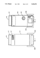
- FIG. 1 is a front elevation view of the laser smoke evacuation system of the instant invention
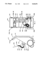
- FIG. 4 is a front elevation view of the laser smoke evacuation system of FIG. 1 with the housing removed to show the components inside.
- FIG. 7 is front elevation view of one embodiment of the front panel
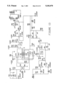
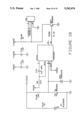
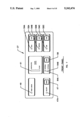
- FIG. 8 is a schematic circuit diagram of the electronic system of the laser smoke evacuation system of this invention.
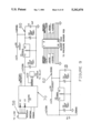
- FIG. 10 is a schematic circuit diagram of another portion of the power supply printed circuit board.
- FIG. 16 is a schematic circuit diagram of another portion of the speed select printed circuit board of FIG. 8;
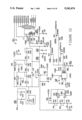
- FIG. 17 is a schematic circuit diagram of the control panel electronic components of the electrical system of FIG. 8.
- FIG. 18 is a schematic circuit diagram of the flow detector printed circuit board of the electronic system of FIG. 8.
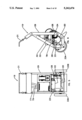
- the laser smoke evacuation system 19 may include a front housing panel 21 and a rear housing panel 25 to shield and protect internal components within the housing panels.
- a control panel 27 may be mounted to a housing panel as illustrated so that it is readily accessible to an operator.
- a frame 29 is structured so that the internal components of the system may be mounted thereto.
- a handle 31 facilitates tilting of the evacuation system onto the wheels 33A and 33B for transport of the system.
- An electric motor 20 is mechanically connected to a vacuum pump 22 by a connection means 23 such as a gear box, or belt drive arrangement. Electric motor 20 mechanically operates pump 22 causing air to be transported from a pump inlet 24 to a pump outlet 26 thereby creating a negative pressure at the pump inlet 24.
- a first suction duct 28 connects pump inlet 24 to the receiver outlet 30 of a filter receiver 32.
- a filter 40 is mounted to the receiver inlet 34 of filter receiver 32.
- Inlet 34 is structured to allow filter 40 to be removed and replaced as required.
- Filter 40 may be a conventional single or multistage filter, or it may be designed according to the requirements of a particular application.
- Filter 40 has an inlet 42 adapted for connection to a second suction duct 44.
- the second suction duct 44 is of sufficient length to extend from filter inlet 42 to a point proximal the surgical site.
- a fluid pathway exists from the surgical site, through the second suction duct 44, filter 40, filter receiver 32, and first suction duct 28 to the negative pressure at pump inlet 24.
- Laser smoke produced during laser surgery may be suctioned into the second suction duct 44 and through filter 40 where particulate matter and potentially harmful components are removed.
- first and second suction ducts 28 and 44 may be constructed from a flexible material such as plastic, fabric or elastomeric material. In a preferred arrangement, first and second suction ducts 28 and 44 are constructed from flexible convoluted tubing. The distal end 44A of the second suction duct 44 may be structured to accommodate installation of a sterilizable nozzle 48 to ensure sterility at the surgical site.
- the pump 22, motor 20 and filter receiver 32 are each mounted to the frame 29 and pump 22 and motor 20 are internal of the front housing panel 21 and the rear housing panel 25.
- Filter receiver 32 projects through the rear housing panel, and mounts the filter 40.
- a control panel may be included on front housing panel 21 to display the status or condition of various components of the smoke evacuation system.
- Switches and indicators pertaining to operation of the smoke evacuation system such as power switch 47 and indicator light 47A, may be mounted on control panel 27.
- the panel 27 provides a convenient and accessible location to consolidate various switches and indicators which may be included with the smoke evacuation system. It is desirable that indicator lights be of the LED variety for reliability and compatibility with other electronic components of the system.
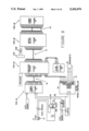
- FIG. 8 is a schematic diagram of a practical electrical circuit for the electronic system of the smoke evacuation system, showing the various printed circuit boards which may be included; namely a power supply board, PCB-10, a pressure board, PCB-20, a speed select board, PCB-30 and a control board PCB-40.
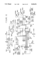
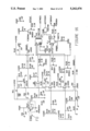
- FIGS. 9-18 are schematic diagrams of practical electrical circuits of the printed circuit boards and other electronic components which may be included in the electronic system. Wherever possible, practical values or manufacturers identification numbers for the illustrated electrical components are included. Pin position and other electronic details are indicated on the drawings in conventional fashion.
- switch S1 shown at the left side of the figure when switch S1 shown at the left side of the figure is closed, power from an AC source (not shown) is supplied through an outlet J1 to the system through fuse F1 and line filter LF1.
- the line filter LF1 may be included to prevent transient interference voltages from entering or leaving the system.
- the high side 56 of the AC line exiting line filter LF1 is applied to solid state relay K1 and to the power supply printed circuit board PCB-10 as indicted by the signal AC HI.
- the low side 57 of the AC line is applied to one side of auto-transformer T1, terminal L1 of AC75U speed controller U1, and to the power supply printed circuit board PCB-10 as indicated by the signal AC LO.
- Switch S5 power
- AC female 15 ⁇ 2 connector J2 the connection of which provides electrical signals SWPOWA and SWPOWB.
- These electrical signals are fed from the control panel printed circuit board PCB-40, through a ribbon cable indicated generally as 75 (FIG. 8), to the speed select printed circuit board PCB-30.
- FIG. 14 shows a portion of the speed select printed circuit board PCB-30 and shows electrical signal SWPOWB connected to ground and signal SWPOWA entering the circuit board at 15 ⁇ 2 Header P1 at pin number 25. Electrical signal SWPOWA exits the circuit board at 12 ⁇ 2 Header P2 at pin number 7.
- the signal SWPOWA leaves the speed select printed circuit board PCB-30 through a ribbon cable indicated generally as 77 (FIG. 8) and enters the pressure sensor printed circuit board PCB-20.
- the other electrical signals indicated on the printed circuit boards PCB-10 through PCB-40 in FIG. 8 enter and exit the printed circuit boards as indicated in FIGS. 9-18.
- the speed select printed circuit board PCB-30 is shown schematically in FIGS. 14, 15, and 16.
- the circuit board is typically designed to cause default to the lowest motor speed when the smoke evacuation system is turned on.
- FIG. 17 shows three speed selection switches S2, S3, and S4. One side of each of these switches is connected to ground, and the other side of each switch attaches to an input of an octal latch U5A as shown in FIG. 15. If a speed other than the default low speed is selected from the control panel, the switch is shorted and the input at octal latch U5A is pulled to a low voltage state. The low voltage input is transferred to the appropriate output pin of octal latch U5A where it latches the signal on the low voltage output.
- FIG. 17 shows the LED connections as electrical signals LEDLO, LEDMED, and LEDHI from female connector J2 and going to the cathodes of diodes D34, D35, or D36. If the medium speed were selected, the electrical signal LEDMED would go to a low voltage state and the LED representing the medium speed (54B, FIG. 7) would lite up. Current flows from the direct current source so, through resistor R3 electrical signal LEDCOM to the appropriate anode of a diode D35 in the control panel circuitry (FIG. 17), and back to the low voltage output of octal latch U5A.
- electric motor 20 is operable in either of two modes.
- the operator may select the motor speed from a plurality of switches 52A, 52B, and 52C on the control panel 27 corresponding to a plurality of preselected motor speeds.
- the motor is coupled to a sensor element 53A by means of a fiber optic cable 53B.
- the motor speed, and thus the available suction, is then controlled in response to an output signal from the sensor element.
- the sensor element may be positioned proximal the surgical site where it is in close proximity to the laser smoke.
- the fiber optic cable conducts a light signal from the sensor element to an electronic circuit which converts the light signal to an electrical signal.
- the electrical signal is converted from the light signal on the speed select printed circuit board PCB-30 which controls the motor speed in response to the signal from the sensor element.
- the external mode ensures an adequate level of evacuation for the level of laser smoke generation. As the amount of smoke changes, the output from the sensor element also changes, and the level of evacuation is adjusted in response. Selection of internal and external modes may be accomplished by actuating a switch 58 located on the control panel 27. Indicator lights 64A and 64B may be used to indicate which of the two operational modes has been selected Indicator lights 54A, 54B, and 54C may be used to indicate which of the preselected motor speeds has been selected. As specifically illustrated, they do so only in the internal mode.
- the speed select printed circuit board PCB-30 controls mode selection as shown by FIGS. 15 and 16.
- the circuit may be designed to default to the internal operational mode when the evacuation system is turned on.
- the electrical circuit for the internal mode is enabled and power is routed to the internal LED indicator 64A on control panel 27.
- a low voltage signal, SWMODE (FIG. 17)
- SWMODE (FIG. 17)
- U5D (FIG. 15)
- Low voltage signal SWMODE triggers an output signal, EXTCLK (FIG. 16), which is sent to dual D flip-flop U3A.
- U3A In response to output signal EXTCLK, U3A produces a high voltage signal, INTCAT, which disables the LOW, MED, and HI control panel switches 52A, 52B, and 52C from interfering with the speed of the vacuum motor. High voltage signal INTCAT also enables flip-flop U3A and turns off the internal LED 64A on the control panel 27. A low voltage signal from dual D flip-flop U3A, EXTCAT (FIG. 15), is fed to the external LED 64B on control panel 27 to illuminate the LED as an indicator that the system is in the external mode. These actions set the system for external speed control. If the mode button 58 is pressed again, the internal LED 64A comes on, the external LED 64B goes off, and the system is returned to internal mode at the lowest speed.
- the vacuum motor 20 speed is controlled in response to an output signal from a sensor element (not shown).
- the intensity of the output signal corresponds to the level of laser smoke production at the surgical site.
- the external device is coupled to the vacuum unit by a fiber optic cable (not shown), the input of which is indicated as FO.
- the fiber optic cable conducts a light signal from the sensor element to the speed control printed circuit board PCB-30.
- the light signal is converted back into an electrical signal within the evacuation system by a fiber optic detector U9.
- the output of detector U9 is pulled to a low voltage through an internal U9 transistor. Current thus flows from the source +12VDC, through resistor R21 to ground.
- the internal output transistor of U9 When light is not present in the fiber optic cable, the internal output transistor of U9 is off and currant flows from +12VDC through R21 and R28, and charges C9 and C15. When the light signal again turns on, the output transistor of U9 turns on, and current not only flows through resistor R21 to ground but also from C9 and C15, through R28, to ground which discharges the capacitors. The ratio of charge time to discharge time determines the average voltage level across capacitors C9 and C15, which in turn determines the speed of the motor 20. If the capacitor voltage is 5 volts for example, comparators U9A, U9B, U9C, and U9D will be in a high voltage state. The output of comparator U8 will be at a low voltage.
- the output potentials of comparators U8, U9A, and U9B are fed to input terminals A, B, and C of decoder U10.
- One output Y0-Y7 of decoder U10 provides a low voltage signal depending upon the binary input combination from the comparators.
- the binary inputs cause the output Y6 to achieve a low voltage state because the B (weighted value of 2) and the C (weighted value of 4) inputs are at high voltage.
- the output Y6 signal EXTMED causes the vacuum motor 20 to run at a medium speed when the signal is in a low voltage state.
- the signal from the sensor element thus varies the ratio of charge time to discharge time of capacitors C9 and C15 which in turn determines the speed of the motor 20.
- motor speed is regulated by a duty cycle when the evacuation system is operated in the external mode.
- an error signal may be produced. This might occur if the fiber optic cable is disconnected or damaged, or if the external control circuit fails.
- An error condition will cause the output signal of either comparitor U9D or U9C shown in FIG. 16 to go to a low voltage state.
- This action activates the clear input signal of flip-flop U10A and causes the output, indicated in FIG. 16 as Q, to go to a low voltage state and the output, designated as Q , to go to a high voltage state.
- the Q output forces the output signal indicated as EXTHIGH of AND gate U10B to go to a low voltage state which causes the motor to go to high speed.
- a filter status indicator means enables a user to determine the functional condition of the filter 40. As the filter 40 becomes clogged, resistance to air-flow through the vacuum pump 22 increases, and consequently air-flow decreases.
- a flow detector 78 may be placed within the flow to detect a decrease in air-flow.
- the flow detector may include a small propeller positioned to rotate in the air-flow. As the flow changes, the speed of the propeller also changes.
- the propeller may be positioned so that the blades pass between an infrared LED emitter (FIG. 18, D1) and a photo-transistor detector. Each time the blade passes between the emitter (D1, FIG. 18) and detector (Q1, FIG. 18), the light beam is interrupted and the photo-transistor changes from on to off.
- the collector of detector Q1 may be selected to provide a square wave output profile with frequency representing the speed of the propeller.
- This output wave may be fed to the input of a one-shot multivibrator formed by dual one-shot multivibrator U11A and other associated components (FIG. 18).
- U11A receives a negative going edge
- a one-shot output is triggered to low voltage for a period defined by the resistor/capacitor network of R6 and C70.
- the result is a square wave output signal which varies in frequency and duty cycle.
- This wave can be applied to a resistor/capacitor filter to obtain a varying DC voltage representing the frequency of the propeller, and consequently the air-flow.
- the gain and offset of the inverting amplifier receiving the output must change with the speed of the pump.
- the gain variation is accomplished by the analog switches U6A and U6B shown in FIG. 12. For example, if high speed is selected, resistors R58, R60 and R57, R59 are shunted by analog switch U6B. Gain is then determined by the ratio between resistors R56, R62, and R61. For example, high gain can be adjusted by turning R62 until the appropriate output voltage from inverting amplifier U7A is obtained. Similar adjustments may be performed for other speed selections.
- the output of dual op-amp U7A may be fed to the input of display driver U7B.
- the display driver U7B compares the incoming signal internally to a series of 10 reference voltages, within U7B, each controlling an output designated as L1-L10. If a reference is exceeded, its corresponding output goes to a low voltage state. As the input signal climbs in intensity, it exceeds an increasing number of reference voltages which sequentially allow additional output potentials to go to a low voltage state.
- These low voltage outputs may be coupled to the filter status LED's 61 located on control panel 27. When the outputs go to low voltage, a shunt is tripped and the LED turns on.
- the series of LED's 61 on the control panel 27 may resemble a bar graph which displays filter status.
- the first LED's to light may be colored green to indicate favorable or clear filter status, while the last LED's to light may be colored red indicating that the filter is clogged and should be replaced. To further emphasize the clogged filter condition, the red LED's may be made to flash on and off.
- the system also provides for automatic compensation of suction capability as the filter becomes progressively clogged.
- the circuit functions by regulating the negative pressure of the vacuum pump 22 at the pump inlet 24 side. Air-flow through the vacuum pump 22 will remain constant provided the resistance to flow remains the same. If a filter is attached to the input, the resistance to flow increases, and consequently the air-flow will decrease.
- a differential voltage output from a pressure sensor U12 is amplified by an instrumentation amplifier formed by the operational amplifiers U13A, U13B, and U133C, and resistor network R30.
- a pressure sensor 82 may be coupled to the vacuum pump 22 between the pump inlet 24 and any attachments such as the filter 40 by a small hose 62.
- An increase in pressure is sensed by pressure sensor U12 which produces an output signal in the form of a differential voltage that increases in amplitude as the negative pressure increases.
- the instrumentation amplifier of U13A, U13B, U13C and resistor network R30 feeds the output to the input of a non-inverting, or error amplifier formed by dual op-amp U14 and associated components illustrated by FIG. 13.
- the output of U14 is applied to the input of the pulse width modulator U15, which subsequently produces a square wave output signal which has a variable duty cycle based on the amplitude of the input signal.
- the duty cycle decreases, thereby slowing the pump and reducing the pressure, across the filter 40.
- the duty cycle will be larger, and the pump speed will increase.
- the circuit senses the change and decreases the pump speed until the proper pressure is attained. If the pressure decreases, the circuit senses the change and increases the pump speed until the proper pressure is attained.
- the proper level of pressure is determined by the output of op-amp U16 shown in FIG. 13.
- a reference voltage is placed on the non-inverting input of U16. It is this voltage that is amplified to varying degrees which determines the pressure level.
- Pressure regulation is accomplished by comparing the pressure generated by the pump to the voltage level provided by op-amp U16. As the voltage level increases, the motor will increase pump speed until the pressure meets the voltage level.
- This circuitry also compensates for barometric pressure when, for example, the system is taken from elevation 4500 feet to sea level. In this situation, the pump 22 will have a higher vacuum capability by as much as 15%.
- the filter status display 62 would likely read clear (excessive air-flow) even when the display should indicate an obstructed filter. Compensation is accomplished by the pressure regulation circuitry. If the pressure produced by the pump 22 increases, the speed of the motor 20 is slightly decreased to offset the increased pressure. This adjustment will bring the generated pressure and air-flow back to the intended level.
Abstract
A surgical laser smoke evacuation system includes a sensor positioned at the surgical site to determine the need for evacuation. A vacuum pump draws smoke from the site through a system of conduits, including an in line filter. The filter tends to become clogged over time. A sensor determines changes in the pressure drop across the filter, and is connected to a control mechanism which adjusts the speed of the vacuum pump to maintain an approximately constant flow across the filter.
Description
This application is a continuation of application Ser. No. 07/786,455, filed Nov. 1, 1991, now abandoned.
1. Field
This application relates to laser smoke evacuation systems used during laser surgical procedures and more specifically to laser smoke evacuation systems with smoke filter obstruction indicators.
2. State of the Art
Laser surgical procedures are widely used for removing excess or diseased tissue. When subjected to the concentrated energy of the laser, the tissue of interest is vaporized into laser smoke. The laser smoke may contain infectious viral or microbial components, and must be evacuated to prevent exposing the surgical staff to these potentially harmful components.
Devices to evacuate laser smoke generated during laser surgery typically employ a motor driven vacuum pump to suction the smoke into the device. The smoke may then be passed through a filter where particulates and potentially harmful materials are removed.
Over time, filtered material clogs the pores of the filter resulting in a change in suction capability and filtering capacity. The filter must then be replaced to maintain a safe environment for the surgical staff. If the filter becomes extensively clogged during surgery, it may be necessary to stop the surgery until the filter can be changed.
Several U.S. patents teach devices to evacuate and filter laser smoke generated during laser surgery. Some of the devices are capable of indicating a clogged filter condition. These devices, however, do not indicate the extent of filter obstruction, or compensate for a change in suction capability as the filter becomes clogged.
It would be useful to know the extent of filter obstruction at all times. A substantially clogged filter could then be replaced before beginning a surgery. It would also be useful if the smoke evacuation system could compensate for a change in suction capability as the filter progressively becomes clogged. Ideally, such a system should be capable of automatically controlling the level of evacuation to correspond with the level of laser smoke production.
A laser smoke evacuation system includes a motor driven vacuum pump and means, such as a filter, for removing harmful components from laser smoke. A filter status response means may be included for monitoring and reacting to the porosity condition of the filter. Porosity condition may be indicated to an operator by an indicator means. In such embodiments, the indicator means may be made to sequentially indicate the porosity condition as the filter becomes progressively less porous due to clogging. A control panel may be included for mounting and displaying various switches and indicators of the smoke evacuation system. In such embodiments, indicator lights sequentially light as the filter becomes progressively more clogged.
Certain embodiments of the invention automatically compensate for changes in suction capability due to progressive clogging of the filter. Suction sensor means may be included to sense and respond to changes in suction capability. In such embodiments, the suction sensor means may be associated with the motor to cause motor speed, and thus vacuum pump speed to change in response to a signal from the suction sensor means. Typically, a pressure sensor associated with the vacuum pump senses changes in negative pressure as the filter becomes clogged, and produces an output signal which corresponds to the negative pressure produced by the pump. The pressure sensor output signal is amplified and applied to an electrical circuit associated with the motor. The output from this circuit increases or decreases the pump speed to maintain a constant level of suction.
Certain embodiments of the invention are operable in either of two modes. In an internal mode, the vacuum pump speed may be selected from a plurality of preselected speeds. Switches corresponding to preselected pump speeds may be located on the front panel for convenience. In an external mode, vacuum pump speed may be automatically determined in response to an output signal from a sensor element linked to the system. The sensor element may be linked to an electronic circuit which controls the speed of the vacuum pump. In the preferred embodiments, the sensor element generates an output signal corresponding to the level of laser smoke production, thereby regulating pump speed proportional to the need for suction at the operative site.
In the drawings, which illustrate what is currently regarded as the best mode for carrying out the invention:
FIG. 1 is a front elevation view of the laser smoke evacuation system of the instant invention;
FIG. 2 is a rear elevation view of the laser smoke evacuation system of FIG. 1;
FIG. 3 is a side elevation view of the laser smoke evacuation system of FIG. 1;
FIG. 4 is a front elevation view of the laser smoke evacuation system of FIG. 1 with the housing removed to show the components inside.
FIG. 5 is a rear elevation view of the laser smoke evacuation system of FIG. 1 with the housing removed;
FIG. 6 is a side elevation view of the laser smoke evacuation system of FIG. 1 with the housing removed;
FIG. 7 is front elevation view of one embodiment of the front panel;
FIG. 8 is a schematic circuit diagram of the electronic system of the laser smoke evacuation system of this invention;
FIG. 9 is a schematic circuit diagram of a portion of the power supply printed circuit board of the electronic system of FIG. 8;
FIG. 10 is a schematic circuit diagram of another portion of the power supply printed circuit board;
FIG. 11 is a schematic circuit diagram of a portion of the pressure sensor printed circuit board of the electronic system of FIG. 8;
FIG. 12 is a schematic circuit diagram of a separate portion of the pressure sensor printed circuit board of FIG. 8;
FIG. 13 is a schematic circuit diagram of another portion of the pressure sensor circuit board of FIG. 8;
FIG. 14 is a schematic circuit diagram of a portion of the speed select printed circuit board of the electronic system of FIG. 8;
FIG. 15 is a schematic circuit diagram of another portion of the speed select printed circuit board of FIG. 8;
FIG. 16 is a schematic circuit diagram of another portion of the speed select printed circuit board of FIG. 8;
FIG. 17 is a schematic circuit diagram of the control panel electronic components of the electrical system of FIG. 8; and
FIG. 18 is a schematic circuit diagram of the flow detector printed circuit board of the electronic system of FIG. 8.
Referring to FIGS. 1-3, the laser smoke evacuation system 19 may include a front housing panel 21 and a rear housing panel 25 to shield and protect internal components within the housing panels. A control panel 27 may be mounted to a housing panel as illustrated so that it is readily accessible to an operator. Referring also to FIGS. 4-6, a frame 29 is structured so that the internal components of the system may be mounted thereto. A handle 31 facilitates tilting of the evacuation system onto the wheels 33A and 33B for transport of the system.
An electric motor 20 is mechanically connected to a vacuum pump 22 by a connection means 23 such as a gear box, or belt drive arrangement. Electric motor 20 mechanically operates pump 22 causing air to be transported from a pump inlet 24 to a pump outlet 26 thereby creating a negative pressure at the pump inlet 24. A first suction duct 28 connects pump inlet 24 to the receiver outlet 30 of a filter receiver 32.
As best shown by FIG. 3, a filter 40 is mounted to the receiver inlet 34 of filter receiver 32. Inlet 34 is structured to allow filter 40 to be removed and replaced as required. Filter 40 may be a conventional single or multistage filter, or it may be designed according to the requirements of a particular application. Filter 40 has an inlet 42 adapted for connection to a second suction duct 44. The second suction duct 44 is of sufficient length to extend from filter inlet 42 to a point proximal the surgical site. A fluid pathway exists from the surgical site, through the second suction duct 44, filter 40, filter receiver 32, and first suction duct 28 to the negative pressure at pump inlet 24. Laser smoke produced during laser surgery may be suctioned into the second suction duct 44 and through filter 40 where particulate matter and potentially harmful components are removed.
The first and second suction ducts 28 and 44 may be constructed from a flexible material such as plastic, fabric or elastomeric material. In a preferred arrangement, first and second suction ducts 28 and 44 are constructed from flexible convoluted tubing. The distal end 44A of the second suction duct 44 may be structured to accommodate installation of a sterilizable nozzle 48 to ensure sterility at the surgical site.
In practice, laser smoke is removed from the atmosphere surrounding an operating area in which the smoke is created. The evacuation system 19 is wheeled into the operating area and motor 20 is connected to a source of power and is turned on. The motor 20 drives the vacuum pump 22.
Pump 22 pulls the ambient air, with the smoke, through a nozzle 48, which has been placed in the area from which smoke is to be removed, duct 44 to which the nozzle is connected, filter 40, filter receiver 32, duct 28, and pump inlet 24 and then discharges the filtered air to atmosphere through the pump outlet 26.
The pump 22, motor 20 and filter receiver 32 are each mounted to the frame 29 and pump 22 and motor 20 are internal of the front housing panel 21 and the rear housing panel 25. Filter receiver 32 projects through the rear housing panel, and mounts the filter 40.
Referring to FIGS. 1 and 7, a control panel, indicated generally as 27, may be included on front housing panel 21 to display the status or condition of various components of the smoke evacuation system. Switches and indicators pertaining to operation of the smoke evacuation system, such as power switch 47 and indicator light 47A, may be mounted on control panel 27. The panel 27 provides a convenient and accessible location to consolidate various switches and indicators which may be included with the smoke evacuation system. It is desirable that indicator lights be of the LED variety for reliability and compatibility with other electronic components of the system.
Electric motor 20 may be of conventional design and appropriately sized to drive vacuum pump 22. In a preferred arrangement, motor 20 may be operated at different speeds. Multi-speed capability may be accomplished by either operating the motor 20 at any of a plurality of preselected motor speeds or through operation in a duty cycle. If a different level of evacuation is desired, the speed of the motor, and hence the speed of the vacuum pump, may be changed to any of the preselected speed settings. Motor speed may be changed by pressing a button, such as one of buttons 52A, 52B, or 52C on the front panel 21, which corresponds to the desired level of evacuation. The appropriate speed indicating light, such as one of indicating lights 54A, 54B, or 54C, will light to indicate the selected motor speed.
FIG. 8 is a schematic diagram of a practical electrical circuit for the electronic system of the smoke evacuation system, showing the various printed circuit boards which may be included; namely a power supply board, PCB-10, a pressure board, PCB-20, a speed select board, PCB-30 and a control board PCB-40. FIGS. 9-18 are schematic diagrams of practical electrical circuits of the printed circuit boards and other electronic components which may be included in the electronic system. Wherever possible, practical values or manufacturers identification numbers for the illustrated electrical components are included. Pin position and other electronic details are indicated on the drawings in conventional fashion.
Referring to FIG. 8, when switch S1 shown at the left side of the figure is closed, power from an AC source (not shown) is supplied through an outlet J1 to the system through fuse F1 and line filter LF1. The line filter LF1 may be included to prevent transient interference voltages from entering or leaving the system. The high side 56 of the AC line exiting line filter LF1 is applied to solid state relay K1 and to the power supply printed circuit board PCB-10 as indicted by the signal AC HI. The low side 57 of the AC line is applied to one side of auto-transformer T1, terminal L1 of AC75U speed controller U1, and to the power supply printed circuit board PCB-10 as indicated by the signal AC LO.
As shown in FIG. 9, the AC HI and AC LO electrical signals (FIG. 8) are applied to the power supply portion 70 of the power supply printed circuit board PCB-10 at pin P1 on header 58. FIG. 10 is a schematic diagram of the power supply portion 70 of FIG. 9. The electrical signal indicated by signals AC HI and AC LO are processed by the circuit illustrated, which delivers a rectified and smoothed positive 17 Volt potential at an output indicated at the right side of FIG. 10 as +17VSW Referring again to FIG. 9, the potential +17VSW exiting the power supply portion 70, is in turn applied to various other components illustrated in FIG. 9, notably the voltage regulators U1 and U2. The +17 Volt potential into a +12 Volt component 60, and a +5 Volt component 62. As shown in FIG. 8, it is these potentials which exit the power supply printed circuit board PCB-10 to supply power to the rest of the electronics within the system.
A practical circuit for the electronics of the control panel 27 is shown schematically by FIG. 17. Switch S5 (power), is connected to AC female 15×2 connector J2, the connection of which provides electrical signals SWPOWA and SWPOWB. These electrical signals are fed from the control panel printed circuit board PCB-40, through a ribbon cable indicated generally as 75 (FIG. 8), to the speed select printed circuit board PCB-30. FIG. 14 shows a portion of the speed select printed circuit board PCB-30 and shows electrical signal SWPOWB connected to ground and signal SWPOWA entering the circuit board at 15×2 Header P1 at pin number 25. Electrical signal SWPOWA exits the circuit board at 12×2 Header P2 at pin number 7. The signal SWPOWA leaves the speed select printed circuit board PCB-30 through a ribbon cable indicated generally as 77 (FIG. 8) and enters the pressure sensor printed circuit board PCB-20. In like manner, the other electrical signals indicated on the printed circuit boards PCB-10 through PCB-40 in FIG. 8, enter and exit the printed circuit boards as indicated in FIGS. 9-18.
The speed select printed circuit board PCB-30 is shown schematically in FIGS. 14, 15, and 16. The circuit board is typically designed to cause default to the lowest motor speed when the smoke evacuation system is turned on. FIG. 17 shows three speed selection switches S2, S3, and S4. One side of each of these switches is connected to ground, and the other side of each switch attaches to an input of an octal latch U5A as shown in FIG. 15. If a speed other than the default low speed is selected from the control panel, the switch is shorted and the input at octal latch U5A is pulled to a low voltage state. The low voltage input is transferred to the appropriate output pin of octal latch U5A where it latches the signal on the low voltage output. U5A output signals are fed to AND gates U5B and U5C and also to the appropriate LED on panel 27. FIG. 17 shows the LED connections as electrical signals LEDLO, LEDMED, and LEDHI from female connector J2 and going to the cathodes of diodes D34, D35, or D36. If the medium speed were selected, the electrical signal LEDMED would go to a low voltage state and the LED representing the medium speed (54B, FIG. 7) would lite up. Current flows from the direct current source so, through resistor R3 electrical signal LEDCOM to the appropriate anode of a diode D35 in the control panel circuitry (FIG. 17), and back to the low voltage output of octal latch U5A.
In a preferred arrangement, electric motor 20 is operable in either of two modes. In an internal mode, the operator may select the motor speed from a plurality of switches 52A, 52B, and 52C on the control panel 27 corresponding to a plurality of preselected motor speeds. In an external mode, the motor is coupled to a sensor element 53A by means of a fiber optic cable 53B. The motor speed, and thus the available suction, is then controlled in response to an output signal from the sensor element. The sensor element may be positioned proximal the surgical site where it is in close proximity to the laser smoke. The fiber optic cable conducts a light signal from the sensor element to an electronic circuit which converts the light signal to an electrical signal. The electrical signal is converted from the light signal on the speed select printed circuit board PCB-30 which controls the motor speed in response to the signal from the sensor element.
The external mode ensures an adequate level of evacuation for the level of laser smoke generation. As the amount of smoke changes, the output from the sensor element also changes, and the level of evacuation is adjusted in response. Selection of internal and external modes may be accomplished by actuating a switch 58 located on the control panel 27. Indicator lights 64A and 64B may be used to indicate which of the two operational modes has been selected Indicator lights 54A, 54B, and 54C may be used to indicate which of the preselected motor speeds has been selected. As specifically illustrated, they do so only in the internal mode.
The speed select printed circuit board PCB-30 controls mode selection as shown by FIGS. 15 and 16. The circuit may be designed to default to the internal operational mode when the evacuation system is turned on. In this arrangement, when power switch 47 is actuated, the electrical circuit for the internal mode is enabled and power is routed to the internal LED indicator 64A on control panel 27. When the mode button 58 is pressed to change to external mode, a low voltage signal, SWMODE (FIG. 17), is fed to a one-shot multivibrator U5D (FIG. 15). Low voltage signal SWMODE triggers an output signal, EXTCLK (FIG. 16), which is sent to dual D flip-flop U3A. In response to output signal EXTCLK, U3A produces a high voltage signal, INTCAT, which disables the LOW, MED, and HI control panel switches 52A, 52B, and 52C from interfering with the speed of the vacuum motor. High voltage signal INTCAT also enables flip-flop U3A and turns off the internal LED 64A on the control panel 27. A low voltage signal from dual D flip-flop U3A, EXTCAT (FIG. 15), is fed to the external LED 64B on control panel 27 to illuminate the LED as an indicator that the system is in the external mode. These actions set the system for external speed control. If the mode button 58 is pressed again, the internal LED 64A comes on, the external LED 64B goes off, and the system is returned to internal mode at the lowest speed.
In the external mode, the vacuum motor 20 speed, and thus the available suction, is controlled in response to an output signal from a sensor element (not shown). The intensity of the output signal corresponds to the level of laser smoke production at the surgical site. As shown in FIG. 16, the external device is coupled to the vacuum unit by a fiber optic cable (not shown), the input of which is indicated as FO. The fiber optic cable conducts a light signal from the sensor element to the speed control printed circuit board PCB-30. The light signal is converted back into an electrical signal within the evacuation system by a fiber optic detector U9. When light is present in the fiber optic cable, the output of detector U9 is pulled to a low voltage through an internal U9 transistor. Current thus flows from the source +12VDC, through resistor R21 to ground. When light is not present in the fiber optic cable, the internal output transistor of U9 is off and currant flows from +12VDC through R21 and R28, and charges C9 and C15. When the light signal again turns on, the output transistor of U9 turns on, and current not only flows through resistor R21 to ground but also from C9 and C15, through R28, to ground which discharges the capacitors. The ratio of charge time to discharge time determines the average voltage level across capacitors C9 and C15, which in turn determines the speed of the motor 20. If the capacitor voltage is 5 volts for example, comparators U9A, U9B, U9C, and U9D will be in a high voltage state. The output of comparator U8 will be at a low voltage. The output potentials of comparators U8, U9A, and U9B are fed to input terminals A, B, and C of decoder U10. One output Y0-Y7 of decoder U10 provides a low voltage signal depending upon the binary input combination from the comparators. In the case illustrated, the binary inputs cause the output Y6 to achieve a low voltage state because the B (weighted value of 2) and the C (weighted value of 4) inputs are at high voltage. The output Y6 signal EXTMED, causes the vacuum motor 20 to run at a medium speed when the signal is in a low voltage state. The signal from the sensor element thus varies the ratio of charge time to discharge time of capacitors C9 and C15 which in turn determines the speed of the motor 20. In this embodiment, motor speed is regulated by a duty cycle when the evacuation system is operated in the external mode.
If the voltage level across capacitors C9 and C15 becomes too high or too low, an error signal may be produced. This might occur if the fiber optic cable is disconnected or damaged, or if the external control circuit fails. An error condition will cause the output signal of either comparitor U9D or U9C shown in FIG. 16 to go to a low voltage state. This action activates the clear input signal of flip-flop U10A and causes the output, indicated in FIG. 16 as Q, to go to a low voltage state and the output, designated as Q , to go to a high voltage state. The Q output forces the output signal indicated as EXTHIGH of AND gate U10B to go to a low voltage state which causes the motor to go to high speed. The output signal of U10A, designated Q , turns on transistor Q8 which turns on the fiber error LED 49 on control panel 27. The function of this circuitry in an error condition is to drive the vacuum motor 20 at high speed to ensure adequate suction. In the internal mode, the current which might normally flow to the fiber error LED 49 is shunted to ground.
A filter status indicator means enables a user to determine the functional condition of the filter 40. As the filter 40 becomes clogged, resistance to air-flow through the vacuum pump 22 increases, and consequently air-flow decreases. A flow detector 78 may be placed within the flow to detect a decrease in air-flow. The flow detector may include a small propeller positioned to rotate in the air-flow. As the flow changes, the speed of the propeller also changes. The propeller may be positioned so that the blades pass between an infrared LED emitter (FIG. 18, D1) and a photo-transistor detector. Each time the blade passes between the emitter (D1, FIG. 18) and detector (Q1, FIG. 18), the light beam is interrupted and the photo-transistor changes from on to off. As the speed of the propeller changes, the frequency of light beam interruption also changes. The collector of detector Q1 may be selected to provide a square wave output profile with frequency representing the speed of the propeller. This output wave may be fed to the input of a one-shot multivibrator formed by dual one-shot multivibrator U11A and other associated components (FIG. 18). When the input of U11A receives a negative going edge, a one-shot output is triggered to low voltage for a period defined by the resistor/capacitor network of R6 and C70. The result is a square wave output signal which varies in frequency and duty cycle. This wave can be applied to a resistor/capacitor filter to obtain a varying DC voltage representing the frequency of the propeller, and consequently the air-flow.
If the pump speed is varied, air-flow also varies, and the output from the resistor/capacitor filter will change. To maintain a uniform output, whether the pump is set to LOW, MED or HIGH speeds, the gain and offset of the inverting amplifier receiving the output must change with the speed of the pump. The gain variation is accomplished by the analog switches U6A and U6B shown in FIG. 12. For example, if high speed is selected, resistors R58, R60 and R57, R59 are shunted by analog switch U6B. Gain is then determined by the ratio between resistors R56, R62, and R61. For example, high gain can be adjusted by turning R62 until the appropriate output voltage from inverting amplifier U7A is obtained. Similar adjustments may be performed for other speed selections.
If the offset is set when the pump is running at high speed, and then the speed is changed, a different offset is applied to inverting amplifier U7A due to the action of the analog switches. Referring again to FIG. 12, when high speed is selected, analog switch U6D is turned on by the signal HIGH, resistors R71 and R70 are shunted, and the offset is adjusted by turning resistor R72. Offsets at other motor speed settings may be adjusted similarly. It is important to adjust the offsets in the order of high speed to low speed because the medium offset will affect the low offset, and the high offset will affect the other two offsets.
As shown in FIG. 12, the output of dual op-amp U7A may be fed to the input of display driver U7B. The display driver U7B compares the incoming signal internally to a series of 10 reference voltages, within U7B, each controlling an output designated as L1-L10. If a reference is exceeded, its corresponding output goes to a low voltage state. As the input signal climbs in intensity, it exceeds an increasing number of reference voltages which sequentially allow additional output potentials to go to a low voltage state. These low voltage outputs may be coupled to the filter status LED's 61 located on control panel 27. When the outputs go to low voltage, a shunt is tripped and the LED turns on. The series of LED's 61 on the control panel 27 may resemble a bar graph which displays filter status. The first LED's to light may be colored green to indicate favorable or clear filter status, while the last LED's to light may be colored red indicating that the filter is clogged and should be replaced. To further emphasize the clogged filter condition, the red LED's may be made to flash on and off.
The system also provides for automatic compensation of suction capability as the filter becomes progressively clogged. The circuit functions by regulating the negative pressure of the vacuum pump 22 at the pump inlet 24 side. Air-flow through the vacuum pump 22 will remain constant provided the resistance to flow remains the same. If a filter is attached to the input, the resistance to flow increases, and consequently the air-flow will decrease.
This discrepancy is alleviated by the circuit illustrated by FIG. 13. A differential voltage output from a pressure sensor U12 is amplified by an instrumentation amplifier formed by the operational amplifiers U13A, U13B, and U133C, and resistor network R30. Referring to FIG. 4, a pressure sensor 82 may be coupled to the vacuum pump 22 between the pump inlet 24 and any attachments such as the filter 40 by a small hose 62. An increase in pressure is sensed by pressure sensor U12 which produces an output signal in the form of a differential voltage that increases in amplitude as the negative pressure increases. The instrumentation amplifier of U13A, U13B, U13C and resistor network R30 feeds the output to the input of a non-inverting, or error amplifier formed by dual op-amp U14 and associated components illustrated by FIG. 13. The output of U14 is applied to the input of the pulse width modulator U15, which subsequently produces a square wave output signal which has a variable duty cycle based on the amplitude of the input signal. As the input signal increases, the duty cycle decreases, thereby slowing the pump and reducing the pressure, across the filter 40. Conversely, as the input decreases, the duty cycle will be larger, and the pump speed will increase. Thus if the pressure at pump inlet 24 increases, the circuit senses the change and decreases the pump speed until the proper pressure is attained. If the pressure decreases, the circuit senses the change and increases the pump speed until the proper pressure is attained.
The proper level of pressure is determined by the output of op-amp U16 shown in FIG. 13. A reference voltage is placed on the non-inverting input of U16. It is this voltage that is amplified to varying degrees which determines the pressure level. Pressure regulation is accomplished by comparing the pressure generated by the pump to the voltage level provided by op-amp U16. As the voltage level increases, the motor will increase pump speed until the pressure meets the voltage level. This circuitry also compensates for barometric pressure when, for example, the system is taken from elevation 4500 feet to sea level. In this situation, the pump 22 will have a higher vacuum capability by as much as 15%. If the evacuation system has no compensation, the filter status display 62 would likely read clear (excessive air-flow) even when the display should indicate an obstructed filter. Compensation is accomplished by the pressure regulation circuitry. If the pressure produced by the pump 22 increases, the speed of the motor 20 is slightly decreased to offset the increased pressure. This adjustment will bring the generated pressure and air-flow back to the intended level.
The foregoing descriptions of the illustrated electronic circuitry are intended to disclose practical circuits having components of practical values and are not intended to limit the scope of the appended claims, which are intended to define the illustrated embodiment and its equivalents.
Claims (26)
1. A smoke evacuation system for removing surgically produced smoke, comprising:
a support frame;
a variable speed electric motor mounted on said frame;
a vacuum pump having an inlet and an outlet mounted on said frame;
means coupling said motor to said pump to drive said pump in response to operation of said motor;
a filter to remove harmful components from surgically produced smoke, said filter having an inlet thereto and an outlet therefrom;
first duct means having one end connected to the outlet of said filter and another end connected to said inlet of said vacuum pump;
second duct means having one end connected to the inlet of said filter and a movable other end to be positioned in an area where smoke is surgically produced; and
means for controlling the speed of said variable speed motor in accordance with the amount of smoke present at said movable other end of said second duct means.
2. A smoke evacuation system as in claim 1, further including manually set speed control means carried by the support frame and connected to said motor to control the speed of operation of said motor according to settings of said speed control means.
3. A smoke evacuation system as in claim 2, further including:
pressure sensing means connected to the inlet of said vacuum pump and generating a signal indicative of the pressure at said inlet; and
circuit means connecting said signal generated by said pressure sensing means to said variable speed motor and to vary the speed of said motor to maintain a substantially constant pressure as initially sensed by said pressure sensor upon actuation of said motor to a speed set by the speed control means.
4. A smoke evacuation system as in claim 2, further including sensor means for detecting the presence of smoke in said area, operably associated with said smoke responsive means.
5. A smoke evacuation system as in claim 2, further including selector switch means to selectively disconnect either the means for controlling the speed of said variable speed motor in accordance with the amount of smoke or the speed control means from control of the said variable speed motor.
6. A smoke evacuation system as in claim 5, further including:
air flow detector means positioned in the path of air flow through said filter and said vacuum pump, said air flow detector operating a signal corresponding to the speed of air flow between said filter and said vacuum pump; and
circuit means connecting said signal generated by said air flow detector to said variable speed motor to change the speed of said motor as required to change the speed of said pump to maintain the air flow detected by said air flow detector as established by said speed control means upon initial setting of said speed control means.
7. A smoke evacuation system as in claim 6, further including:
pressure sensing means connected to the inlet of said vacuum pump and generating a signal indicative of the pressure at said inlet; and
circuit means connecting said signal generated by said pressure sensing means to said variable speed motor and to vary the speed of said motor to maintain a substantially constant pressure as initially sensed by said pressure sensing means upon actuation of said motor to a speed set by the speed control means.
8. A smoke evacuation system as in claim 7, further including:
a front panel carried by the support frame; and
indicator means carried by said front panel, said indicator means indicating a filter status display means.
9. A smoke evacuation system as in claim 8, further including circuit means connecting said air flow detector means and said filter display means, whereby air flow detected by said flow detector means is displayed on said filter status display means as an indication of air flow through said filter.
10. A smoke evacuation system as in claim 9, further including circuit means connecting said pressure sensing means and said filter display means, whereby pressure detected by said pressure sensing means is displayed on said filter status display means as an indication of air flow through said filter.
11. A smoke evacuation system as in claim 8, wherein the indicator means carried by the front panel further includes means to indicate the on/off status of the variable speed motor.
12. A smoke evacuation system as in claim 11, wherein the indicator means carried by the front panel further includes means to indicate mode selection of the motor to an internal mode, wherein speed of said motor is controlled by a setting of said manually set speed control means or an external mode, wherein speed of said motor is controlled by said smoke responsive means.
13. A smoke evacuation system as in claim 12, wherein the indicator means carried by the front panel further includes means to indicate selected motor speed when the mode selection indicator indicates said motor to be in an internal mode.
14. A smoke evacuation system as in claim 5, further including means to default the speed control means to a setting for lowest motor speed upon initial actuation of said motor.
15. A smoke evacuation system as in claim 2, further including:
air flow detector means positioned in the path of air flow from said filter through said vacuum pump, said air flow detector generating a signal corresponding to the speed of air flow between said filter and said vacuum pump; and
circuit means connecting said signal generated by said air flow detector to said variable speed motor to change the speed of said motor as required to change the speed of said pump to maintain the air flow detected by said air flow detector as established by said speed control means upon initial setting of said speed control means.
16. A smoke evacuation system as in claim 15, further including:
a front panel carried by the support frame; and
indicator means carried by said front panel, said indicator means indicating a filter status display means.
17. A smoke evacuation system as in claim 16, further including circuit means connecting said air flow detector means and said filter display means, whereby air flow detected by said flow detector means is displayed on said filter status display means as an indication of air flow through said filter.
18. A smoke evacuation system as in claim 16, further including circuit means connecting said pressure sensing means and said filter display means, whereby pressure detected by said pressure sensing means is displayed on said filter status display means as an indication of air flow through said filter.
19. A smoke evacuation system as in claim 18, further including circuit means connecting said air flow detector means and said filter display means, whereby air flow detected by said flow detector means is displayed on said filter status display means as an indication of air flow through said filter.
20. A smoke evacuation system as in claim 19, wherein the indicator means carried by the front panel further includes means to indicate the on/off status of the variable speed motor.
21. A smoke evacuation system as in claim 20, wherein the indicator means carried by the front panel further includes means to indicate mode selection of the motor to an internal mode, wherein speed of said motor is controlled by a setting of said manually set speed control means or an external mode, wherein the speed of said motor is controlled by said smoke responsive means.
22. A smoke evacuation system as in claim 21, wherein the indicator means carried by the front panel further includes means to indicate selected motor speed when the mode selection indicator indicates said motor to be in an internal mode.
23. A smoke evacuation system as in claim 22, wherein the indicator means carried by the front panel further includes an error indicator to indicate failure of said smoke responsive means.
24. A smoke evacuation system as in claim 19, wherein the indicator means carried by the front panel further includes means to indicate mode selection of the motor to an internal mode, wherein speed of said motor is controlled by a setting of said manually set speed control means or an external mode, wherein the speed of said motor is controlled by said smoke responsive means.
25. A smoke evacuation system as in claim 19, wherein the indicator means carried by the front panel further includes means to indicate selected motor speed when the mode selection indicator indicates said motor to be in an internal mode.
26. A smoke evacuation system as in claim 19, wherein the indicator means carried by the front panel further includes an error indicator to indicate failure of the smoke responsive means for controlling the speed of said variable speed motor in accordance with the amount of smoke detected by said sensor means.
Priority Applications (1)
| Application Number | Priority Date | Filing Date | Title |
|---|---|---|---|
| US07/974,378 US5242474A (en) | 1991-11-01 | 1992-11-10 | Dual mode laser smoke evacuation system with sequential filter monitor and vacuum compensation |
Applications Claiming Priority (2)
| Application Number | Priority Date | Filing Date | Title |
|---|---|---|---|
| US78645591A | 1991-11-01 | 1991-11-01 | |
| US07/974,378 US5242474A (en) | 1991-11-01 | 1992-11-10 | Dual mode laser smoke evacuation system with sequential filter monitor and vacuum compensation |
Related Parent Applications (1)
| Application Number | Title | Priority Date | Filing Date |
|---|---|---|---|
| US07/706,455 Continuation US5182422A (en) | 1990-05-25 | 1991-05-28 | Electric switch, especially for operating a windshield wiper and washer system of a motor vehicle |
Publications (1)
| Publication Number | Publication Date |
|---|---|
| US5242474A true US5242474A (en) | 1993-09-07 |
Family
ID=25138637
Family Applications (1)
| Application Number | Title | Priority Date | Filing Date |
|---|---|---|---|
| US07/974,378 Expired - Fee Related US5242474A (en) | 1991-11-01 | 1992-11-10 | Dual mode laser smoke evacuation system with sequential filter monitor and vacuum compensation |
Country Status (4)
| Country | Link |
|---|---|
| US (1) | US5242474A (en) |
| EP (1) | EP0642376A4 (en) |
| CA (1) | CA2122594A1 (en) |
| WO (1) | WO1993008897A1 (en) |
Cited By (180)
| Publication number | Priority date | Publication date | Assignee | Title |
|---|---|---|---|---|
| US5409511A (en) * | 1992-12-03 | 1995-04-25 | Michaud, Cooley, Erickson & Associates, Inc. | Centralized laser plume evacuation system through articulating arms |
| US5674219A (en) * | 1994-10-06 | 1997-10-07 | Donaldson Company, Inc. | Electrosurgical smoke evacuator |
| US5968032A (en) * | 1998-03-30 | 1999-10-19 | Sleister; Dennis R. | Smoke evacuator for a surgical laser or cautery plume |
| US6045596A (en) * | 1997-04-07 | 2000-04-04 | Medtek Devices, Inc. | Filter system to remove a contaminant from a fluid stream |
| DE19852706A1 (en) * | 1998-11-16 | 2000-06-08 | Atmos Medizintechnik Gmbh & Co | Suction device, which aspirates airborne or airborne waste products from a surgical treatment with a current-driven surgical instrument, in particular with a laser scalpel, with an activation unit |
| US6110259A (en) * | 1997-11-21 | 2000-08-29 | Jlj International, Inc. | Smoke evacuation system |
| US6203590B1 (en) * | 1999-03-25 | 2001-03-20 | Steris Corp | Surgical smoke evacuation system with replaceable filter cartridge module and accumulated filter usage display |
| US20050000196A1 (en) * | 2003-07-03 | 2005-01-06 | Schultz Leonard S. | Smoke evacuation system |
| US20050060974A1 (en) * | 2003-09-15 | 2005-03-24 | Palmerton Christopher A. | Operating room smoke evacuator with integrated vacuum motor and filter |
| US20070000501A1 (en) * | 2005-07-01 | 2007-01-04 | Wert Lindsay T | Surgical procedure supplemental accessory controller and method utilizing turn-on and turn-off time delays |
| US20070135779A1 (en) * | 2005-12-14 | 2007-06-14 | Stryker Corporation | Medical/surgical waste collection and disposal system including waste containers of different storage volumes with inter-container transfer valve and independently controlled vacuum levels |
| US20070205720A1 (en) * | 2005-11-23 | 2007-09-06 | Integrated Sensing Systems, Inc. | Getter device |
| US20080048047A1 (en) * | 2006-08-28 | 2008-02-28 | Air Products And Chemicals, Inc. | Cryogenic Nozzle |
| WO2009032689A3 (en) * | 2007-08-28 | 2009-09-03 | Air Products And Chemicals, Inc. | Apparatus and method for monitoring and regulating cryogenic cooling |
| US20100290923A1 (en) * | 2009-05-12 | 2010-11-18 | Hong Fu Jin Precision Industry (Shenzhen) Co., Ltd. | Fan assembly |
| US8025173B2 (en) | 2006-09-07 | 2011-09-27 | Allegiance Corporation | Collapsible canister liner for medical fluid collection |
| WO2012142225A1 (en) * | 2011-04-15 | 2012-10-18 | Martins Maintenance, Inc. | Vacuum cleaner and vacuum cleaning system and methods of use in a raised floor environment |
| US8460256B2 (en) | 2009-07-15 | 2013-06-11 | Allegiance Corporation | Collapsible fluid collection and disposal system and related methods |
| US8500706B2 (en) | 2007-03-23 | 2013-08-06 | Allegiance Corporation | Fluid collection and disposal system having interchangeable collection and other features and methods relating thereto |
| US8518002B2 (en) | 2005-12-14 | 2013-08-27 | Stryker Corporation | Removable inlet manifold for a medical/surgical waste collection system, the manifold include a backflow prevention valve that seats on a portion of the manifold |
| US20140260996A1 (en) * | 2013-03-15 | 2014-09-18 | Illinois Tool Works Inc. | Portable industrial air filtration device |
| CN104135960A (en) * | 2011-10-07 | 2014-11-05 | 埃杰亚医疗公司 | Integrity testing method and apparatus for delivering vapor to the uterus |
| US20150112246A1 (en) * | 2011-12-01 | 2015-04-23 | Christopher A. Palmerton | Filtration System and Method |
| USD758558S1 (en) | 2014-03-10 | 2016-06-07 | Illinois Tool Works Inc. | Air filtration device |
| USD761946S1 (en) | 2014-09-12 | 2016-07-19 | Illinois Tool Works Inc. | Filter for an air filtration device |
| US9517428B2 (en) | 2014-09-12 | 2016-12-13 | Illinois Tool Works Inc. | Filter for a portable industrial air filtration device |
| US9532843B2 (en) | 2012-02-14 | 2017-01-03 | Buffalo Filter Llc | Medical boom filter system and method |
| USD785775S1 (en) | 2013-03-15 | 2017-05-02 | Illinois Tool Works Inc. | Cover for an air filtration device |
| US9743974B2 (en) | 2010-11-09 | 2017-08-29 | Aegea Medical Inc. | Positioning method and apparatus for delivering vapor to the uterus |
| USD797273S1 (en) | 2013-03-15 | 2017-09-12 | Illinois Tool Works Inc. | Air filtration device filter pin |
| DE102016207666A1 (en) * | 2016-05-03 | 2017-11-09 | Olympus Winter & Ibe Gmbh | Medical smoke evacuation apparatus and method of operating the same |
| US20180021822A1 (en) * | 2016-07-20 | 2018-01-25 | SPAWAR System Center Pacific | Transmission Window Cleanliness for Directed Energy Devices |
| US9889239B2 (en) | 2007-03-23 | 2018-02-13 | Allegiance Corporation | Fluid collection and disposal system and related methods |
| US9993290B2 (en) | 2014-05-22 | 2018-06-12 | Aegea Medical Inc. | Systems and methods for performing endometrial ablation |
| US10154871B2 (en) | 2007-08-23 | 2018-12-18 | Aegea Medical Inc. | Uterine therapy device and method |
| US10179019B2 (en) | 2014-05-22 | 2019-01-15 | Aegea Medical Inc. | Integrity testing method and apparatus for delivering vapor to the uterus |
| WO2019106548A1 (en) * | 2017-11-29 | 2019-06-06 | Megadyne Medical Products, Inc. | Noise and vibration management for smoke evacuation system |
| EP3505120A1 (en) * | 2017-12-28 | 2019-07-03 | Ethicon LLC | Adjustments based on airborne particle properties |
| EP3506303A1 (en) * | 2017-12-28 | 2019-07-03 | Ethicon LLC | Surgical evacuation sensing and motor control |
| US20190201086A1 (en) * | 2017-12-28 | 2019-07-04 | Ethicon Llc | Surgical evacuation sensing and display |
| WO2019130117A1 (en) * | 2017-12-28 | 2019-07-04 | Ethicon Llc | Surgical evacuation sensing and motor control |
| US20190201045A1 (en) * | 2017-12-28 | 2019-07-04 | Ethicon Llc | Method for smoke evacuation for surgical hub |
| US10471188B1 (en) | 2019-04-12 | 2019-11-12 | Stryker Corporation | Manifold for filtering medical waste being drawn under vacuum into a medical waste collection system |
| USD868236S1 (en) | 2017-11-29 | 2019-11-26 | Megadyne Medical Products, Inc. | Smoke evacuation device control panel |
| USD868287S1 (en) | 2017-11-29 | 2019-11-26 | Megadyne Medical Products, Inc. | Remote activation clip |
| US10595887B2 (en) | 2017-12-28 | 2020-03-24 | Ethicon Llc | Systems for adjusting end effector parameters based on perioperative information |
| US10631916B2 (en) | 2017-11-29 | 2020-04-28 | Megadyne Medical Products, Inc. | Filter connection for a smoke evacuation device |
| USD886976S1 (en) | 2017-11-29 | 2020-06-09 | Megadyne Medical Products, Inc. | Filter cartridge |
| US10695081B2 (en) | 2017-12-28 | 2020-06-30 | Ethicon Llc | Controlling a surgical instrument according to sensed closure parameters |
| US10755813B2 (en) | 2017-12-28 | 2020-08-25 | Ethicon Llc | Communication of smoke evacuation system parameters to hub or cloud in smoke evacuation module for interactive surgical platform |
| US10758855B2 (en) | 2017-11-29 | 2020-09-01 | Megadyne Medical Products, Inc. | Smoke evacuation system fluid trap |
| US10758293B2 (en) | 2017-11-29 | 2020-09-01 | Megadyne Medical Products, Inc. | Smoke evacuation device inlet and outlet manifolds |
| US10758310B2 (en) | 2017-12-28 | 2020-09-01 | Ethicon Llc | Wireless pairing of a surgical device with another device within a sterile surgical field based on the usage and situational awareness of devices |
| US10758856B2 (en) | 2017-11-29 | 2020-09-01 | Megadyne Medical Products, Inc. | Filter medium compression system for smoke evacuation |
| US10772651B2 (en) | 2017-10-30 | 2020-09-15 | Ethicon Llc | Surgical instruments comprising a system for articulation and rotation compensation |
| US10849697B2 (en) | 2017-12-28 | 2020-12-01 | Ethicon Llc | Cloud interface for coupled surgical devices |
| US10892899B2 (en) | 2017-12-28 | 2021-01-12 | Ethicon Llc | Self describing data packets generated at an issuing instrument |
| US10892995B2 (en) | 2017-12-28 | 2021-01-12 | Ethicon Llc | Surgical network determination of prioritization of communication, interaction, or processing based on system or device needs |
| US10898622B2 (en) | 2017-12-28 | 2021-01-26 | Ethicon Llc | Surgical evacuation system with a communication circuit for communication between a filter and a smoke evacuation device |
| US10932872B2 (en) | 2017-12-28 | 2021-03-02 | Ethicon Llc | Cloud-based medical analytics for linking of local usage trends with the resource acquisition behaviors of larger data set |
| US10944728B2 (en) | 2017-12-28 | 2021-03-09 | Ethicon Llc | Interactive surgical systems with encrypted communication capabilities |
| USD912762S1 (en) | 2017-11-29 | 2021-03-09 | Megadyne Medical Products, Inc. | Fluid trap |
| US10943454B2 (en) | 2017-12-28 | 2021-03-09 | Ethicon Llc | Detection and escalation of security responses of surgical instruments to increasing severity threats |
| JP2021509328A (en) * | 2017-12-28 | 2021-03-25 | エシコン エルエルシーEthicon LLC | Smoke exhaust system with segmented control circuitry for interactive surgical platforms |
| JP2021509334A (en) * | 2017-12-28 | 2021-03-25 | エシコン エルエルシーEthicon LLC | Adjustment based on suspended particle characteristics |
| US10966791B2 (en) | 2017-12-28 | 2021-04-06 | Ethicon Llc | Cloud-based medical analytics for medical facility segmented individualization of instrument function |
| US10973520B2 (en) | 2018-03-28 | 2021-04-13 | Ethicon Llc | Surgical staple cartridge with firing member driven camming assembly that has an onboard tissue cutting feature |
| US10987178B2 (en) | 2017-12-28 | 2021-04-27 | Ethicon Llc | Surgical hub control arrangements |
| USD919799S1 (en) | 2019-11-11 | 2021-05-18 | Stryker Corporation | Manifold housing for a medical waste collection device |
| US11013563B2 (en) | 2017-12-28 | 2021-05-25 | Ethicon Llc | Drive arrangements for robot-assisted surgical platforms |
| US11026687B2 (en) | 2017-10-30 | 2021-06-08 | Cilag Gmbh International | Clip applier comprising clip advancing systems |
| US11026751B2 (en) | 2017-12-28 | 2021-06-08 | Cilag Gmbh International | Display of alignment of staple cartridge to prior linear staple line |
| US11056244B2 (en) | 2017-12-28 | 2021-07-06 | Cilag Gmbh International | Automated data scaling, alignment, and organizing based on predefined parameters within surgical networks |
| US11051876B2 (en) | 2017-12-28 | 2021-07-06 | Cilag Gmbh International | Surgical evacuation flow paths |
| US11058498B2 (en) | 2017-12-28 | 2021-07-13 | Cilag Gmbh International | Cooperative surgical actions for robot-assisted surgical platforms |
| US11069012B2 (en) | 2017-12-28 | 2021-07-20 | Cilag Gmbh International | Interactive surgical systems with condition handling of devices and data capabilities |
| US11076921B2 (en) | 2017-12-28 | 2021-08-03 | Cilag Gmbh International | Adaptive control program updates for surgical hubs |
| US11090047B2 (en) | 2018-03-28 | 2021-08-17 | Cilag Gmbh International | Surgical instrument comprising an adaptive control system |
| US11100631B2 (en) | 2017-12-28 | 2021-08-24 | Cilag Gmbh International | Use of laser light and red-green-blue coloration to determine properties of back scattered light |
| US11096693B2 (en) | 2017-12-28 | 2021-08-24 | Cilag Gmbh International | Adjustment of staple height of at least one row of staples based on the sensed tissue thickness or force in closing |
| US11096688B2 (en) | 2018-03-28 | 2021-08-24 | Cilag Gmbh International | Rotary driven firing members with different anvil and channel engagement features |
| US11114195B2 (en) | 2017-12-28 | 2021-09-07 | Cilag Gmbh International | Surgical instrument with a tissue marking assembly |
| US11109866B2 (en) | 2017-12-28 | 2021-09-07 | Cilag Gmbh International | Method for circular stapler control algorithm adjustment based on situational awareness |
| US11129611B2 (en) | 2018-03-28 | 2021-09-28 | Cilag Gmbh International | Surgical staplers with arrangements for maintaining a firing member thereof in a locked configuration unless a compatible cartridge has been installed therein |
| US11132462B2 (en) | 2017-12-28 | 2021-09-28 | Cilag Gmbh International | Data stripping method to interrogate patient records and create anonymized record |
| US11147607B2 (en) | 2017-12-28 | 2021-10-19 | Cilag Gmbh International | Bipolar combination device that automatically adjusts pressure based on energy modality |
| US11166772B2 (en) | 2017-12-28 | 2021-11-09 | Cilag Gmbh International | Surgical hub coordination of control and communication of operating room devices |
| US11179208B2 (en) | 2017-12-28 | 2021-11-23 | Cilag Gmbh International | Cloud-based medical analytics for security and authentication trends and reactive measures |
| US11179175B2 (en) | 2017-12-28 | 2021-11-23 | Cilag Gmbh International | Controlling an ultrasonic surgical instrument according to tissue location |
| US11185808B2 (en) * | 2017-09-05 | 2021-11-30 | Husqvarna Ab | Separator and method of operating a separator |
| US11202570B2 (en) | 2017-12-28 | 2021-12-21 | Cilag Gmbh International | Communication hub and storage device for storing parameters and status of a surgical device to be shared with cloud based analytics systems |
| US11207118B2 (en) | 2007-07-06 | 2021-12-28 | Tsunami Medtech, Llc | Medical system and method of use |
| US11207067B2 (en) | 2018-03-28 | 2021-12-28 | Cilag Gmbh International | Surgical stapling device with separate rotary driven closure and firing systems and firing member that engages both jaws while firing |
| US11219453B2 (en) | 2018-03-28 | 2022-01-11 | Cilag Gmbh International | Surgical stapling devices with cartridge compatible closure and firing lockout arrangements |
| US11229436B2 (en) | 2017-10-30 | 2022-01-25 | Cilag Gmbh International | Surgical system comprising a surgical tool and a surgical hub |
| US11234756B2 (en) | 2017-12-28 | 2022-02-01 | Cilag Gmbh International | Powered surgical tool with predefined adjustable control algorithm for controlling end effector parameter |
| US11234754B2 (en) | 2017-11-29 | 2022-02-01 | Megadyne Medical Products, Inc. | Smoke evacuation device |
| US11257589B2 (en) | 2017-12-28 | 2022-02-22 | Cilag Gmbh International | Real-time analysis of comprehensive cost of all instrumentation used in surgery utilizing data fluidity to track instruments through stocking and in-house processes |
| US11253315B2 (en) | 2017-12-28 | 2022-02-22 | Cilag Gmbh International | Increasing radio frequency to create pad-less monopolar loop |
| US11259830B2 (en) | 2018-03-08 | 2022-03-01 | Cilag Gmbh International | Methods for controlling temperature in ultrasonic device |
| US11259807B2 (en) | 2019-02-19 | 2022-03-01 | Cilag Gmbh International | Staple cartridges with cam surfaces configured to engage primary and secondary portions of a lockout of a surgical stapling device |
| US11259806B2 (en) | 2018-03-28 | 2022-03-01 | Cilag Gmbh International | Surgical stapling devices with features for blocking advancement of a camming assembly of an incompatible cartridge installed therein |
| US11266468B2 (en) | 2017-12-28 | 2022-03-08 | Cilag Gmbh International | Cooperative utilization of data derived from secondary sources by intelligent surgical hubs |
| US11273001B2 (en) | 2017-12-28 | 2022-03-15 | Cilag Gmbh International | Surgical hub and modular device response adjustment based on situational awareness |
| US11278280B2 (en) | 2018-03-28 | 2022-03-22 | Cilag Gmbh International | Surgical instrument comprising a jaw closure lockout |
| US11278281B2 (en) | 2017-12-28 | 2022-03-22 | Cilag Gmbh International | Interactive surgical system |
| US11284931B2 (en) | 2009-02-03 | 2022-03-29 | Tsunami Medtech, Llc | Medical systems and methods for ablating and absorbing tissue |
| US11284936B2 (en) | 2017-12-28 | 2022-03-29 | Cilag Gmbh International | Surgical instrument having a flexible electrode |
| US11291495B2 (en) | 2017-12-28 | 2022-04-05 | Cilag Gmbh International | Interruption of energy due to inadvertent capacitive coupling |
| US11291510B2 (en) | 2017-10-30 | 2022-04-05 | Cilag Gmbh International | Method of hub communication with surgical instrument systems |
| US11298148B2 (en) | 2018-03-08 | 2022-04-12 | Cilag Gmbh International | Live time tissue classification using electrical parameters |
| US11304720B2 (en) | 2017-12-28 | 2022-04-19 | Cilag Gmbh International | Activation of energy devices |
| US11304763B2 (en) | 2017-12-28 | 2022-04-19 | Cilag Gmbh International | Image capturing of the areas outside the abdomen to improve placement and control of a surgical device in use |
| US11304699B2 (en) | 2017-12-28 | 2022-04-19 | Cilag Gmbh International | Method for adaptive control schemes for surgical network control and interaction |
| US11308075B2 (en) | 2017-12-28 | 2022-04-19 | Cilag Gmbh International | Surgical network, instrument, and cloud responses based on validation of received dataset and authentication of its source and integrity |
| US11311306B2 (en) | 2017-12-28 | 2022-04-26 | Cilag Gmbh International | Surgical systems for detecting end effector tissue distribution irregularities |
| US11311342B2 (en) | 2017-10-30 | 2022-04-26 | Cilag Gmbh International | Method for communicating with surgical instrument systems |
| US11318242B2 (en) | 2019-04-12 | 2022-05-03 | Stryker Corporation | Manifold for a medical waste collection system |
| US11317915B2 (en) | 2019-02-19 | 2022-05-03 | Cilag Gmbh International | Universal cartridge based key feature that unlocks multiple lockout arrangements in different surgical staplers |
| US11317919B2 (en) | 2017-10-30 | 2022-05-03 | Cilag Gmbh International | Clip applier comprising a clip crimping system |
| US11317937B2 (en) | 2018-03-08 | 2022-05-03 | Cilag Gmbh International | Determining the state of an ultrasonic end effector |
| USD950728S1 (en) | 2019-06-25 | 2022-05-03 | Cilag Gmbh International | Surgical staple cartridge |
| US11324557B2 (en) | 2017-12-28 | 2022-05-10 | Cilag Gmbh International | Surgical instrument with a sensing array |
| USD952144S1 (en) | 2019-06-25 | 2022-05-17 | Cilag Gmbh International | Surgical staple cartridge retainer with firing system authentication key |
| US11331037B2 (en) | 2016-02-19 | 2022-05-17 | Aegea Medical Inc. | Methods and apparatus for determining the integrity of a bodily cavity |
| US11337746B2 (en) | 2018-03-08 | 2022-05-24 | Cilag Gmbh International | Smart blade and power pulsing |
| US11357503B2 (en) | 2019-02-19 | 2022-06-14 | Cilag Gmbh International | Staple cartridge retainers with frangible retention features and methods of using same |
| US11364075B2 (en) | 2017-12-28 | 2022-06-21 | Cilag Gmbh International | Radio frequency energy device for delivering combined electrical signals |
| US11369377B2 (en) | 2019-02-19 | 2022-06-28 | Cilag Gmbh International | Surgical stapling assembly with cartridge based retainer configured to unlock a firing lockout |
| USD956967S1 (en) | 2019-11-11 | 2022-07-05 | Stryker Corporation | Manifold housing for a medical waste collection device |
| US11376002B2 (en) | 2017-12-28 | 2022-07-05 | Cilag Gmbh International | Surgical instrument cartridge sensor assemblies |
| US11389225B2 (en) | 2017-11-29 | 2022-07-19 | Megadyne Medical Products, Inc. | Smoke evacuation device remote activation system |
| US11389164B2 (en) | 2017-12-28 | 2022-07-19 | Cilag Gmbh International | Method of using reinforced flexible circuits with multiple sensors to optimize performance of radio frequency devices |
| US11410259B2 (en) | 2017-12-28 | 2022-08-09 | Cilag Gmbh International | Adaptive control program updates for surgical devices |
| US11413086B2 (en) | 2013-03-15 | 2022-08-16 | Tsunami Medtech, Llc | Medical system and method of use |
| US11424027B2 (en) | 2017-12-28 | 2022-08-23 | Cilag Gmbh International | Method for operating surgical instrument systems |
| US11419667B2 (en) | 2017-12-28 | 2022-08-23 | Cilag Gmbh International | Ultrasonic energy device which varies pressure applied by clamp arm to provide threshold control pressure at a cut progression location |
| US11423007B2 (en) | 2017-12-28 | 2022-08-23 | Cilag Gmbh International | Adjustment of device control programs based on stratified contextual data in addition to the data |
| US11419630B2 (en) | 2017-12-28 | 2022-08-23 | Cilag Gmbh International | Surgical system distributed processing |
| US11432885B2 (en) | 2017-12-28 | 2022-09-06 | Cilag Gmbh International | Sensing arrangements for robot-assisted surgical platforms |
| US11446052B2 (en) | 2017-12-28 | 2022-09-20 | Cilag Gmbh International | Variation of radio frequency and ultrasonic power level in cooperation with varying clamp arm pressure to achieve predefined heat flux or power applied to tissue |
| USD964564S1 (en) | 2019-06-25 | 2022-09-20 | Cilag Gmbh International | Surgical staple cartridge retainer with a closure system authentication key |
| US11464535B2 (en) | 2017-12-28 | 2022-10-11 | Cilag Gmbh International | Detection of end effector emersion in liquid |
| US11464511B2 (en) | 2019-02-19 | 2022-10-11 | Cilag Gmbh International | Surgical staple cartridges with movable authentication key arrangements |
| US11464559B2 (en) | 2017-12-28 | 2022-10-11 | Cilag Gmbh International | Estimating state of ultrasonic end effector and control system therefor |
| US11471156B2 (en) | 2018-03-28 | 2022-10-18 | Cilag Gmbh International | Surgical stapling devices with improved rotary driven closure systems |
| US11504192B2 (en) | 2014-10-30 | 2022-11-22 | Cilag Gmbh International | Method of hub communication with surgical instrument systems |
| US11510741B2 (en) | 2017-10-30 | 2022-11-29 | Cilag Gmbh International | Method for producing a surgical instrument comprising a smart electrical system |
| US11529187B2 (en) | 2017-12-28 | 2022-12-20 | Cilag Gmbh International | Surgical evacuation sensor arrangements |
| US11540855B2 (en) | 2017-12-28 | 2023-01-03 | Cilag Gmbh International | Controlling activation of an ultrasonic surgical instrument according to the presence of tissue |
| US11559308B2 (en) | 2017-12-28 | 2023-01-24 | Cilag Gmbh International | Method for smart energy device infrastructure |
| US11559307B2 (en) | 2017-12-28 | 2023-01-24 | Cilag Gmbh International | Method of robotic hub communication, detection, and control |
| US11564756B2 (en) | 2017-10-30 | 2023-01-31 | Cilag Gmbh International | Method of hub communication with surgical instrument systems |
| US11571234B2 (en) | 2017-12-28 | 2023-02-07 | Cilag Gmbh International | Temperature control of ultrasonic end effector and control system therefor |
| US11576677B2 (en) | 2017-12-28 | 2023-02-14 | Cilag Gmbh International | Method of hub communication, processing, display, and cloud analytics |
| US11589888B2 (en) | 2017-12-28 | 2023-02-28 | Cilag Gmbh International | Method for controlling smart energy devices |
| US11589932B2 (en) | 2017-12-28 | 2023-02-28 | Cilag Gmbh International | Usage and technique analysis of surgeon / staff performance against a baseline to optimize device utilization and performance for both current and future procedures |
| US11596291B2 (en) | 2017-12-28 | 2023-03-07 | Cilag Gmbh International | Method of compressing tissue within a stapling device and simultaneously displaying of the location of the tissue within the jaws |
| US11602393B2 (en) | 2017-12-28 | 2023-03-14 | Cilag Gmbh International | Surgical evacuation sensing and generator control |
| US11607640B2 (en) * | 2017-09-05 | 2023-03-21 | Husqvarna Ab | Separator, separator system and methods of their operation |
| US11659023B2 (en) | 2017-12-28 | 2023-05-23 | Cilag Gmbh International | Method of hub communication |
| US11666331B2 (en) | 2017-12-28 | 2023-06-06 | Cilag Gmbh International | Systems for detecting proximity of surgical end effector to cancerous tissue |
| USD996640S1 (en) | 2019-11-11 | 2023-08-22 | Stryker Corporation | Specimen collection tray |
| US11744604B2 (en) | 2017-12-28 | 2023-09-05 | Cilag Gmbh International | Surgical instrument with a hardware-only control circuit |
| US11771487B2 (en) | 2017-12-28 | 2023-10-03 | Cilag Gmbh International | Mechanisms for controlling different electromechanical systems of an electrosurgical instrument |
| US11786251B2 (en) | 2017-12-28 | 2023-10-17 | Cilag Gmbh International | Method for adaptive control schemes for surgical network control and interaction |
| US11786245B2 (en) | 2017-12-28 | 2023-10-17 | Cilag Gmbh International | Surgical systems with prioritized data transmission capabilities |
| US11801098B2 (en) | 2017-10-30 | 2023-10-31 | Cilag Gmbh International | Method of hub communication with surgical instrument systems |
| US11818052B2 (en) | 2017-12-28 | 2023-11-14 | Cilag Gmbh International | Surgical network determination of prioritization of communication, interaction, or processing based on system or device needs |
| US11832840B2 (en) | 2017-12-28 | 2023-12-05 | Cilag Gmbh International | Surgical instrument having a flexible circuit |
| US11832899B2 (en) | 2017-12-28 | 2023-12-05 | Cilag Gmbh International | Surgical systems with autonomously adjustable control programs |
| US11857152B2 (en) | 2017-12-28 | 2024-01-02 | Cilag Gmbh International | Surgical hub spatial awareness to determine devices in operating theater |
| US11864728B2 (en) | 2017-12-28 | 2024-01-09 | Cilag Gmbh International | Characterization of tissue irregularities through the use of mono-chromatic light refractivity |
| US11871901B2 (en) | 2012-05-20 | 2024-01-16 | Cilag Gmbh International | Method for situational awareness for surgical network or surgical network connected device capable of adjusting function based on a sensed situation or usage |
| US11896322B2 (en) | 2017-12-28 | 2024-02-13 | Cilag Gmbh International | Sensing the patient position and contact utilizing the mono-polar return pad electrode to provide situational awareness to the hub |
| US11896443B2 (en) | 2017-12-28 | 2024-02-13 | Cilag Gmbh International | Control of a surgical system through a surgical barrier |
| US11903601B2 (en) | 2017-12-28 | 2024-02-20 | Cilag Gmbh International | Surgical instrument comprising a plurality of drive systems |
| US11911045B2 (en) | 2017-10-30 | 2024-02-27 | Cllag GmbH International | Method for operating a powered articulating multi-clip applier |
| US11937769B2 (en) | 2017-12-28 | 2024-03-26 | Cilag Gmbh International | Method of hub communication, processing, storage and display |
| US11969216B2 (en) | 2018-11-06 | 2024-04-30 | Cilag Gmbh International | Surgical network recommendations from real time analysis of procedure variables against a baseline highlighting differences from the optimal solution |
Families Citing this family (3)
| Publication number | Priority date | Publication date | Assignee | Title |
|---|---|---|---|---|
| DE102010015899B4 (en) * | 2010-02-04 | 2022-07-28 | Erbe Elektromedizin Gmbh | Electrosurgical assembly and electrosurgical instrument |
| BR112020013067A2 (en) * | 2017-12-28 | 2020-12-01 | Ethicon Llc | detection and display of surgical evacuation |
| WO2022035979A1 (en) * | 2020-08-12 | 2022-02-17 | Patientpocket LLC | Self-contained surgical smoke detoxifier |
Citations (9)
| Publication number | Priority date | Publication date | Assignee | Title |
|---|---|---|---|---|
| US3518814A (en) * | 1967-03-28 | 1970-07-07 | Smith Corp A O | Airflow control for a dust-free bench |
| US3811250A (en) * | 1971-12-15 | 1974-05-21 | Becton Dickinson Co | Contamination control apparatus |
| US4257746A (en) * | 1978-10-02 | 1981-03-24 | E. I. Du Pont De Nemours And Company | Dosimeter having a low air flow rate |
| US4642128A (en) * | 1985-09-11 | 1987-02-10 | Xanar, Inc. | Smoke evacuator system with electronic control circuitry |
| US4786295A (en) * | 1987-10-01 | 1988-11-22 | Gpac, Inc. | Filtration device for airborne contaminants |
| US4810269A (en) * | 1988-04-27 | 1989-03-07 | Stackhouse Associates, Inc. | Point one micron filtering system |
| US4963134A (en) * | 1989-03-03 | 1990-10-16 | United States Medical Corporation | Laser surgery plume evacuator with aspirator |
| US4986839A (en) * | 1988-11-10 | 1991-01-22 | Surgical Laser Products, Inc. | Self-contained air enhancement and laser plume evacuation system |
| US5047072A (en) * | 1988-11-10 | 1991-09-10 | Surgical Laser Products, Inc. | Ultraviolet air enhancement and laser plume evacuation method and system |
-
1992
- 1992-10-30 WO PCT/US1992/009328 patent/WO1993008897A1/en not_active Application Discontinuation
- 1992-10-30 CA CA002122594A patent/CA2122594A1/en not_active Abandoned
- 1992-10-30 EP EP92924165A patent/EP0642376A4/en not_active Ceased
- 1992-11-10 US US07/974,378 patent/US5242474A/en not_active Expired - Fee Related
Patent Citations (9)
| Publication number | Priority date | Publication date | Assignee | Title |
|---|---|---|---|---|
| US3518814A (en) * | 1967-03-28 | 1970-07-07 | Smith Corp A O | Airflow control for a dust-free bench |
| US3811250A (en) * | 1971-12-15 | 1974-05-21 | Becton Dickinson Co | Contamination control apparatus |
| US4257746A (en) * | 1978-10-02 | 1981-03-24 | E. I. Du Pont De Nemours And Company | Dosimeter having a low air flow rate |
| US4642128A (en) * | 1985-09-11 | 1987-02-10 | Xanar, Inc. | Smoke evacuator system with electronic control circuitry |
| US4786295A (en) * | 1987-10-01 | 1988-11-22 | Gpac, Inc. | Filtration device for airborne contaminants |
| US4810269A (en) * | 1988-04-27 | 1989-03-07 | Stackhouse Associates, Inc. | Point one micron filtering system |
| US4986839A (en) * | 1988-11-10 | 1991-01-22 | Surgical Laser Products, Inc. | Self-contained air enhancement and laser plume evacuation system |
| US5047072A (en) * | 1988-11-10 | 1991-09-10 | Surgical Laser Products, Inc. | Ultraviolet air enhancement and laser plume evacuation method and system |
| US4963134A (en) * | 1989-03-03 | 1990-10-16 | United States Medical Corporation | Laser surgery plume evacuator with aspirator |
Cited By (330)
| Publication number | Priority date | Publication date | Assignee | Title |
|---|---|---|---|---|
| US5409511A (en) * | 1992-12-03 | 1995-04-25 | Michaud, Cooley, Erickson & Associates, Inc. | Centralized laser plume evacuation system through articulating arms |
| US5674219A (en) * | 1994-10-06 | 1997-10-07 | Donaldson Company, Inc. | Electrosurgical smoke evacuator |
| US6045596A (en) * | 1997-04-07 | 2000-04-04 | Medtek Devices, Inc. | Filter system to remove a contaminant from a fluid stream |
| US7258712B2 (en) | 1997-11-21 | 2007-08-21 | Jlj Medical Devices International, Llc | Smoke evacuation system |
| US20050102981A1 (en) * | 1997-11-21 | 2005-05-19 | Schultz Leonard S. | Smoke evacuation system |
| US6110259A (en) * | 1997-11-21 | 2000-08-29 | Jlj International, Inc. | Smoke evacuation system |
| US7789946B2 (en) | 1997-11-21 | 2010-09-07 | Jlj Medical Devices International, Inc. | Smoke evacuation system |
| US6589316B1 (en) | 1997-11-21 | 2003-07-08 | Leonard S. Schultz | Smoke evacuation system |
| US20030183082A1 (en) * | 1997-11-21 | 2003-10-02 | Schultz Leonard S. | Smoke evacuation system |
| US20070225664A1 (en) * | 1997-11-21 | 2007-09-27 | Jlj Medical Devices International, Llc | Smoke evacuation system |
| US20110041468A1 (en) * | 1997-11-21 | 2011-02-24 | JLJ Medical Devices International LLC, a Minnesota corporation | Smoke Evacuation System |
| US6881236B2 (en) | 1997-11-21 | 2005-04-19 | Leonard S. Schultz | Smoke evacuation system |
| US7959698B2 (en) | 1997-11-21 | 2011-06-14 | Coopersurgical, Inc. | Smoke evacuation system |
| US5968032A (en) * | 1998-03-30 | 1999-10-19 | Sleister; Dennis R. | Smoke evacuator for a surgical laser or cautery plume |
| DE19852706A1 (en) * | 1998-11-16 | 2000-06-08 | Atmos Medizintechnik Gmbh & Co | Suction device, which aspirates airborne or airborne waste products from a surgical treatment with a current-driven surgical instrument, in particular with a laser scalpel, with an activation unit |
| US6203590B1 (en) * | 1999-03-25 | 2001-03-20 | Steris Corp | Surgical smoke evacuation system with replaceable filter cartridge module and accumulated filter usage display |
| US20050000196A1 (en) * | 2003-07-03 | 2005-01-06 | Schultz Leonard S. | Smoke evacuation system |
| US20090288561A1 (en) * | 2003-09-15 | 2009-11-26 | Medtek Devices, Inc. | Operating room smoke evacuator with integrated vacuum motor and filter |
| US20050060974A1 (en) * | 2003-09-15 | 2005-03-24 | Palmerton Christopher A. | Operating room smoke evacuator with integrated vacuum motor and filter |
| US7892337B2 (en) | 2003-09-15 | 2011-02-22 | Medtek Devices Inc. | Operating room smoke evacuator with integrated vacuum motor and filter |
| US7597731B2 (en) * | 2003-09-15 | 2009-10-06 | Medtek Devices, Inc. | Operating room smoke evacuator with integrated vacuum motor and filter |
| US20070000501A1 (en) * | 2005-07-01 | 2007-01-04 | Wert Lindsay T | Surgical procedure supplemental accessory controller and method utilizing turn-on and turn-off time delays |
| US7789949B2 (en) * | 2005-11-23 | 2010-09-07 | Integrated Sensing Systems, Inc. | Getter device |
| US20070205720A1 (en) * | 2005-11-23 | 2007-09-06 | Integrated Sensing Systems, Inc. | Getter device |
| US11130089B2 (en) | 2005-12-14 | 2021-09-28 | Stryker Corporation | Waste collection unit with a control system for regulating levels of vacuums being drawn in waste containers |
| US11684442B2 (en) | 2005-12-14 | 2023-06-27 | Stryker Corporation | Methods of assembling a manifold for a medical waste collection system |
| US9782524B2 (en) | 2005-12-14 | 2017-10-10 | Stryker Corporation | Surgical waste collection unit with a manifold receiver that is offset relative to the horizontal |
| US10722617B2 (en) | 2005-12-14 | 2020-07-28 | Stryker Corporation | Manifold including a data carrier for a medical/surgical waste collection assembly |
| US20100049152A1 (en) * | 2005-12-14 | 2010-02-25 | Stryker Corporation | Medical/surgical waste collection and disposal system including a rover and a docker, the docker having features facilitating the alignment of the docker with the rover |
| US11801108B2 (en) | 2005-12-14 | 2023-10-31 | Stryker Corporation | Methods of assembling a manifold for a medical waste collection system |
| US20070135779A1 (en) * | 2005-12-14 | 2007-06-14 | Stryker Corporation | Medical/surgical waste collection and disposal system including waste containers of different storage volumes with inter-container transfer valve and independently controlled vacuum levels |
| US8915897B2 (en) | 2005-12-14 | 2014-12-23 | Stryker Corporation | Removable inlet manifold for a medical/surgical waste collection system, the manifold including a housing with a drip stop, the drip stop projecting out of the housing |
| EP2359878A3 (en) * | 2005-12-14 | 2012-03-28 | Stryker Corporation | Medical/surgical waste evacuator that continually monitors air drawn into the evacuator |
| US11045590B2 (en) | 2005-12-14 | 2021-06-29 | Stryker Corporation | Removable manifold for a medical/surgical waste collection unit |
| US9579428B1 (en) | 2005-12-14 | 2017-02-28 | Stryker Corporation | Surgical waste collection assembly with a manifold receiver and a manifold with complementary features that faciliate the alignment of the manifold with the manifold receiver |
| US10343102B2 (en) | 2005-12-14 | 2019-07-09 | Stryker Corporation | Medical/surgical waste collection portable rover capable of zero setting a float used to measure the volume of liquid in a waste container |
| US8518002B2 (en) | 2005-12-14 | 2013-08-27 | Stryker Corporation | Removable inlet manifold for a medical/surgical waste collection system, the manifold include a backflow prevention valve that seats on a portion of the manifold |
| US8740866B2 (en) | 2005-12-14 | 2014-06-03 | Stryker Corporation | Medical/surgical waste collection and disposal system including a rover and a docker, the docker having features facilitating the alignment of the docker with the rover |
| US7621898B2 (en) | 2005-12-14 | 2009-11-24 | Stryker Corporation | Medical/surgical waste collection unit including waste containers of different storage volumes with inter-container transfer valve and independently controlled vacuum levels |
| US20080048047A1 (en) * | 2006-08-28 | 2008-02-28 | Air Products And Chemicals, Inc. | Cryogenic Nozzle |
| US9200356B2 (en) | 2006-08-28 | 2015-12-01 | Air Products And Chemicals, Inc. | Apparatus and method for regulating cryogenic spraying |
| US9770540B2 (en) | 2006-09-07 | 2017-09-26 | Allegiance Corporation | Collapsible canister liner for medical fluid collection |
| US8025173B2 (en) | 2006-09-07 | 2011-09-27 | Allegiance Corporation | Collapsible canister liner for medical fluid collection |
| US9604778B2 (en) | 2007-03-23 | 2017-03-28 | Allegiance Corporation | Fluid collection and disposal system having interchangeable collection and other features and methods relating thereto |
| US8500706B2 (en) | 2007-03-23 | 2013-08-06 | Allegiance Corporation | Fluid collection and disposal system having interchangeable collection and other features and methods relating thereto |
| US9889239B2 (en) | 2007-03-23 | 2018-02-13 | Allegiance Corporation | Fluid collection and disposal system and related methods |
| US10252856B2 (en) | 2007-03-23 | 2019-04-09 | Allegiance Corporation | Fluid collection and disposal system having interchangeable collection and other features and methods relating thereof |
| US11207118B2 (en) | 2007-07-06 | 2021-12-28 | Tsunami Medtech, Llc | Medical system and method of use |
| US10154871B2 (en) | 2007-08-23 | 2018-12-18 | Aegea Medical Inc. | Uterine therapy device and method |
| US11213338B2 (en) | 2007-08-23 | 2022-01-04 | Aegea Medical Inc. | Uterine therapy device and method |
| US10758292B2 (en) | 2007-08-23 | 2020-09-01 | Aegea Medical Inc. | Uterine therapy device and method |
| WO2009032689A3 (en) * | 2007-08-28 | 2009-09-03 | Air Products And Chemicals, Inc. | Apparatus and method for monitoring and regulating cryogenic cooling |
| US20110083447A1 (en) * | 2007-08-28 | 2011-04-14 | Air Products And Chemicals, Inc. | Apparatus and method for monitoring and regulating cryogenic cooling |
| US11284931B2 (en) | 2009-02-03 | 2022-03-29 | Tsunami Medtech, Llc | Medical systems and methods for ablating and absorbing tissue |
| US20100290923A1 (en) * | 2009-05-12 | 2010-11-18 | Hong Fu Jin Precision Industry (Shenzhen) Co., Ltd. | Fan assembly |
| US8460256B2 (en) | 2009-07-15 | 2013-06-11 | Allegiance Corporation | Collapsible fluid collection and disposal system and related methods |
| US11457969B2 (en) | 2010-08-13 | 2022-10-04 | Tsunami Medtech, Llc | Medical system and method of use |
| US10238446B2 (en) | 2010-11-09 | 2019-03-26 | Aegea Medical Inc. | Positioning method and apparatus for delivering vapor to the uterus |
| US11160597B2 (en) | 2010-11-09 | 2021-11-02 | Aegea Medical Inc. | Positioning method and apparatus for delivering vapor to the uterus |
| US9743974B2 (en) | 2010-11-09 | 2017-08-29 | Aegea Medical Inc. | Positioning method and apparatus for delivering vapor to the uterus |
| US9888820B2 (en) | 2011-04-15 | 2018-02-13 | Martins Maintenance, Inc. | Vacuum cleaner and vacuum cleaning system and methods of use in a raised floor environment |
| JP2014514091A (en) * | 2011-04-15 | 2014-06-19 | マーチンズ メインテナンス, インク. | Vacuum cleaner and vacuum cleaning system in OA floor environment and method of use thereof |
| WO2012142225A1 (en) * | 2011-04-15 | 2012-10-18 | Martins Maintenance, Inc. | Vacuum cleaner and vacuum cleaning system and methods of use in a raised floor environment |
| US9119512B2 (en) | 2011-04-15 | 2015-09-01 | Martins Maintenance, Inc. | Vacuum cleaner and vacuum cleaning system and methods of use in a raised floor environment |
| CN104135960A (en) * | 2011-10-07 | 2014-11-05 | 埃杰亚医疗公司 | Integrity testing method and apparatus for delivering vapor to the uterus |
| US9662060B2 (en) | 2011-10-07 | 2017-05-30 | Aegea Medical Inc. | Integrity testing method and apparatus for delivering vapor to the uterus |
| EP2763617A4 (en) * | 2011-10-07 | 2015-11-18 | Aegea Medical Inc | Integrity testing method and apparatus for delivering vapor to the uterus |
| US10881442B2 (en) | 2011-10-07 | 2021-01-05 | Aegea Medical Inc. | Integrity testing method and apparatus for delivering vapor to the uterus |
| US20150112246A1 (en) * | 2011-12-01 | 2015-04-23 | Christopher A. Palmerton | Filtration System and Method |
| US10004856B2 (en) * | 2011-12-01 | 2018-06-26 | Buffalo Filter Llc | Filtration system and method |
| US10376339B2 (en) | 2012-02-14 | 2019-08-13 | Conmed Corporation | Medical boom filter system and method |
| US9532843B2 (en) | 2012-02-14 | 2017-01-03 | Buffalo Filter Llc | Medical boom filter system and method |
| US11871901B2 (en) | 2012-05-20 | 2024-01-16 | Cilag Gmbh International | Method for situational awareness for surgical network or surgical network connected device capable of adjusting function based on a sensed situation or usage |
| US11672584B2 (en) | 2013-03-15 | 2023-06-13 | Tsunami Medtech, Llc | Medical system and method of use |
| US20140260996A1 (en) * | 2013-03-15 | 2014-09-18 | Illinois Tool Works Inc. | Portable industrial air filtration device |
| USD785775S1 (en) | 2013-03-15 | 2017-05-02 | Illinois Tool Works Inc. | Cover for an air filtration device |
| US11413086B2 (en) | 2013-03-15 | 2022-08-16 | Tsunami Medtech, Llc | Medical system and method of use |
| US9700821B2 (en) | 2013-03-15 | 2017-07-11 | Illinois Tool Works Inc. | Portable industrial air filtration device |
| USD797273S1 (en) | 2013-03-15 | 2017-09-12 | Illinois Tool Works Inc. | Air filtration device filter pin |
| US9776117B2 (en) * | 2013-03-15 | 2017-10-03 | Illinois Tool Works Inc. | Portable industrial air filtration device |
| USD785154S1 (en) | 2014-03-10 | 2017-04-25 | Illinois Tool Works Inc. | Air filtration device |
| USD785153S1 (en) | 2014-03-10 | 2017-04-25 | Illinois Tool Works Inc. | Air filtration device |
| USD758558S1 (en) | 2014-03-10 | 2016-06-07 | Illinois Tool Works Inc. | Air filtration device |
| US9993290B2 (en) | 2014-05-22 | 2018-06-12 | Aegea Medical Inc. | Systems and methods for performing endometrial ablation |
| US10575898B2 (en) | 2014-05-22 | 2020-03-03 | Aegea Medical Inc. | Systems and methods for performing endometrial ablation |
| US11219479B2 (en) | 2014-05-22 | 2022-01-11 | Aegea Medical Inc. | Integrity testing method and apparatus for delivering vapor to the uterus |
| US10179019B2 (en) | 2014-05-22 | 2019-01-15 | Aegea Medical Inc. | Integrity testing method and apparatus for delivering vapor to the uterus |
| US10299856B2 (en) | 2014-05-22 | 2019-05-28 | Aegea Medical Inc. | Systems and methods for performing endometrial ablation |
| US9517428B2 (en) | 2014-09-12 | 2016-12-13 | Illinois Tool Works Inc. | Filter for a portable industrial air filtration device |
| US10226729B2 (en) | 2014-09-12 | 2019-03-12 | Illinois Tool Works Inc. | Filter for a portable industrial air filtration device |
| USD761946S1 (en) | 2014-09-12 | 2016-07-19 | Illinois Tool Works Inc. | Filter for an air filtration device |
| US11504192B2 (en) | 2014-10-30 | 2022-11-22 | Cilag Gmbh International | Method of hub communication with surgical instrument systems |
| US11331037B2 (en) | 2016-02-19 | 2022-05-17 | Aegea Medical Inc. | Methods and apparatus for determining the integrity of a bodily cavity |
| DE102016207666A1 (en) * | 2016-05-03 | 2017-11-09 | Olympus Winter & Ibe Gmbh | Medical smoke evacuation apparatus and method of operating the same |
| DE102016207666B4 (en) | 2016-05-03 | 2023-03-02 | Olympus Winter & Ibe Gmbh | Medical smoke evacuation apparatus and method of operating the same |
| US20180021822A1 (en) * | 2016-07-20 | 2018-01-25 | SPAWAR System Center Pacific | Transmission Window Cleanliness for Directed Energy Devices |
| US10307803B2 (en) * | 2016-07-20 | 2019-06-04 | The United States Of America As Represented By Secretary Of The Navy | Transmission window cleanliness for directed energy devices |
| US11185808B2 (en) * | 2017-09-05 | 2021-11-30 | Husqvarna Ab | Separator and method of operating a separator |
| US11607640B2 (en) * | 2017-09-05 | 2023-03-21 | Husqvarna Ab | Separator, separator system and methods of their operation |
| US11207090B2 (en) | 2017-10-30 | 2021-12-28 | Cilag Gmbh International | Surgical instruments comprising a biased shifting mechanism |
| US11103268B2 (en) | 2017-10-30 | 2021-08-31 | Cilag Gmbh International | Surgical clip applier comprising adaptive firing control |
| US10772651B2 (en) | 2017-10-30 | 2020-09-15 | Ethicon Llc | Surgical instruments comprising a system for articulation and rotation compensation |
| US11141160B2 (en) | 2017-10-30 | 2021-10-12 | Cilag Gmbh International | Clip applier comprising a motor controller |
| US11925373B2 (en) | 2017-10-30 | 2024-03-12 | Cilag Gmbh International | Surgical suturing instrument comprising a non-circular needle |
| US11911045B2 (en) | 2017-10-30 | 2024-02-27 | Cllag GmbH International | Method for operating a powered articulating multi-clip applier |
| US11229436B2 (en) | 2017-10-30 | 2022-01-25 | Cilag Gmbh International | Surgical system comprising a surgical tool and a surgical hub |
| US11819231B2 (en) | 2017-10-30 | 2023-11-21 | Cilag Gmbh International | Adaptive control programs for a surgical system comprising more than one type of cartridge |
| US11801098B2 (en) | 2017-10-30 | 2023-10-31 | Cilag Gmbh International | Method of hub communication with surgical instrument systems |
| US10932806B2 (en) | 2017-10-30 | 2021-03-02 | Ethicon Llc | Reactive algorithm for surgical system |
| US11129636B2 (en) | 2017-10-30 | 2021-09-28 | Cilag Gmbh International | Surgical instruments comprising an articulation drive that provides for high articulation angles |
| US11793537B2 (en) | 2017-10-30 | 2023-10-24 | Cilag Gmbh International | Surgical instrument comprising an adaptive electrical system |
| US11123070B2 (en) | 2017-10-30 | 2021-09-21 | Cilag Gmbh International | Clip applier comprising a rotatable clip magazine |
| US11759224B2 (en) | 2017-10-30 | 2023-09-19 | Cilag Gmbh International | Surgical instrument systems comprising handle arrangements |
| US11109878B2 (en) | 2017-10-30 | 2021-09-07 | Cilag Gmbh International | Surgical clip applier comprising an automatic clip feeding system |
| US11696778B2 (en) | 2017-10-30 | 2023-07-11 | Cilag Gmbh International | Surgical dissectors configured to apply mechanical and electrical energy |
| US10959744B2 (en) | 2017-10-30 | 2021-03-30 | Ethicon Llc | Surgical dissectors and manufacturing techniques |
| US11648022B2 (en) | 2017-10-30 | 2023-05-16 | Cilag Gmbh International | Surgical instrument systems comprising battery arrangements |
| US11291465B2 (en) | 2017-10-30 | 2022-04-05 | Cilag Gmbh International | Surgical instruments comprising a lockable end effector socket |
| US10980560B2 (en) | 2017-10-30 | 2021-04-20 | Ethicon Llc | Surgical instrument systems comprising feedback mechanisms |
| US11602366B2 (en) | 2017-10-30 | 2023-03-14 | Cilag Gmbh International | Surgical suturing instrument configured to manipulate tissue using mechanical and electrical power |
| US11564703B2 (en) | 2017-10-30 | 2023-01-31 | Cilag Gmbh International | Surgical suturing instrument comprising a capture width which is larger than trocar diameter |
| US11564756B2 (en) | 2017-10-30 | 2023-01-31 | Cilag Gmbh International | Method of hub communication with surgical instrument systems |
| US11026687B2 (en) | 2017-10-30 | 2021-06-08 | Cilag Gmbh International | Clip applier comprising clip advancing systems |
| US11510741B2 (en) | 2017-10-30 | 2022-11-29 | Cilag Gmbh International | Method for producing a surgical instrument comprising a smart electrical system |
| US11026713B2 (en) | 2017-10-30 | 2021-06-08 | Cilag Gmbh International | Surgical clip applier configured to store clips in a stored state |
| US11026712B2 (en) | 2017-10-30 | 2021-06-08 | Cilag Gmbh International | Surgical instruments comprising a shifting mechanism |
| US11291510B2 (en) | 2017-10-30 | 2022-04-05 | Cilag Gmbh International | Method of hub communication with surgical instrument systems |
| US11311342B2 (en) | 2017-10-30 | 2022-04-26 | Cilag Gmbh International | Method for communicating with surgical instrument systems |
| US11045197B2 (en) | 2017-10-30 | 2021-06-29 | Cilag Gmbh International | Clip applier comprising a movable clip magazine |
| US11051836B2 (en) | 2017-10-30 | 2021-07-06 | Cilag Gmbh International | Surgical clip applier comprising an empty clip cartridge lockout |
| US11317919B2 (en) | 2017-10-30 | 2022-05-03 | Cilag Gmbh International | Clip applier comprising a clip crimping system |
| US11413042B2 (en) | 2017-10-30 | 2022-08-16 | Cilag Gmbh International | Clip applier comprising a reciprocating clip advancing member |
| US11406390B2 (en) | 2017-10-30 | 2022-08-09 | Cilag Gmbh International | Clip applier comprising interchangeable clip reloads |
| US11071560B2 (en) | 2017-10-30 | 2021-07-27 | Cilag Gmbh International | Surgical clip applier comprising adaptive control in response to a strain gauge circuit |
| US11389225B2 (en) | 2017-11-29 | 2022-07-19 | Megadyne Medical Products, Inc. | Smoke evacuation device remote activation system |
| USD868287S1 (en) | 2017-11-29 | 2019-11-26 | Megadyne Medical Products, Inc. | Remote activation clip |
| USD868236S1 (en) | 2017-11-29 | 2019-11-26 | Megadyne Medical Products, Inc. | Smoke evacuation device control panel |
| US10758293B2 (en) | 2017-11-29 | 2020-09-01 | Megadyne Medical Products, Inc. | Smoke evacuation device inlet and outlet manifolds |
| US11305223B2 (en) | 2017-11-29 | 2022-04-19 | Megadyne Medical Products, Inc. | Smoke evacuation system fluid trap |
| USD967384S1 (en) | 2017-11-29 | 2022-10-18 | Megadyne Medical Products, Inc. | Fluid trap |
| US11185363B2 (en) | 2017-11-29 | 2021-11-30 | Megadyne Medical Products, Inc. | Filter connection for a smoke evacuation device |
| US10758856B2 (en) | 2017-11-29 | 2020-09-01 | Megadyne Medical Products, Inc. | Filter medium compression system for smoke evacuation |
| US11725664B2 (en) * | 2017-11-29 | 2023-08-15 | Megadyne Medical Products, Inc. | Noise and vibration management for smoke evacuation system |
| USD943058S1 (en) | 2017-11-29 | 2022-02-08 | Megadyne Medical Products, Inc. | Filter cartridge |
| USD912762S1 (en) | 2017-11-29 | 2021-03-09 | Megadyne Medical Products, Inc. | Fluid trap |
| US20230340958A1 (en) * | 2017-11-29 | 2023-10-26 | Megadyne Medical Products, Inc. | Noise and vibration management for smoke evacuation system |
| US10758855B2 (en) | 2017-11-29 | 2020-09-01 | Megadyne Medical Products, Inc. | Smoke evacuation system fluid trap |
| US11234754B2 (en) | 2017-11-29 | 2022-02-01 | Megadyne Medical Products, Inc. | Smoke evacuation device |
| WO2019106548A1 (en) * | 2017-11-29 | 2019-06-06 | Megadyne Medical Products, Inc. | Noise and vibration management for smoke evacuation system |
| CN111867668A (en) * | 2017-11-29 | 2020-10-30 | 迈韵医疗器材股份有限公司 | Filter attachment for a smoke exhaust device |
| US10631916B2 (en) | 2017-11-29 | 2020-04-28 | Megadyne Medical Products, Inc. | Filter connection for a smoke evacuation device |
| USD886976S1 (en) | 2017-11-29 | 2020-06-09 | Megadyne Medical Products, Inc. | Filter cartridge |
| US11633237B2 (en) | 2017-12-28 | 2023-04-25 | Cilag Gmbh International | Usage and technique analysis of surgeon / staff performance against a baseline to optimize device utilization and performance for both current and future procedures |
| US11712303B2 (en) | 2017-12-28 | 2023-08-01 | Cilag Gmbh International | Surgical instrument comprising a control circuit |
| US11166772B2 (en) | 2017-12-28 | 2021-11-09 | Cilag Gmbh International | Surgical hub coordination of control and communication of operating room devices |
| US11179204B2 (en) | 2017-12-28 | 2021-11-23 | Cilag Gmbh International | Wireless pairing of a surgical device with another device within a sterile surgical field based on the usage and situational awareness of devices |
| US11179208B2 (en) | 2017-12-28 | 2021-11-23 | Cilag Gmbh International | Cloud-based medical analytics for security and authentication trends and reactive measures |
| US11179175B2 (en) | 2017-12-28 | 2021-11-23 | Cilag Gmbh International | Controlling an ultrasonic surgical instrument according to tissue location |
| US11160605B2 (en) | 2017-12-28 | 2021-11-02 | Cilag Gmbh International | Surgical evacuation sensing and motor control |
| CN111566750A (en) * | 2017-12-28 | 2020-08-21 | 爱惜康有限责任公司 | Surgical evacuation sensing and motor control |
| US11937769B2 (en) | 2017-12-28 | 2024-03-26 | Cilag Gmbh International | Method of hub communication, processing, storage and display |
| US11202570B2 (en) | 2017-12-28 | 2021-12-21 | Cilag Gmbh International | Communication hub and storage device for storing parameters and status of a surgical device to be shared with cloud based analytics systems |
| US10695081B2 (en) | 2017-12-28 | 2020-06-30 | Ethicon Llc | Controlling a surgical instrument according to sensed closure parameters |
| US11931110B2 (en) | 2017-12-28 | 2024-03-19 | Cilag Gmbh International | Surgical instrument comprising a control system that uses input from a strain gage circuit |
| US10755813B2 (en) | 2017-12-28 | 2020-08-25 | Ethicon Llc | Communication of smoke evacuation system parameters to hub or cloud in smoke evacuation module for interactive surgical platform |
| US11147607B2 (en) | 2017-12-28 | 2021-10-19 | Cilag Gmbh International | Bipolar combination device that automatically adjusts pressure based on energy modality |
| US10849697B2 (en) | 2017-12-28 | 2020-12-01 | Ethicon Llc | Cloud interface for coupled surgical devices |
| US11213359B2 (en) | 2017-12-28 | 2022-01-04 | Cilag Gmbh International | Controllers for robot-assisted surgical platforms |
| US11918302B2 (en) | 2017-12-28 | 2024-03-05 | Cilag Gmbh International | Sterile field interactive control displays |
| US10758310B2 (en) | 2017-12-28 | 2020-09-01 | Ethicon Llc | Wireless pairing of a surgical device with another device within a sterile surgical field based on the usage and situational awareness of devices |
| US11132462B2 (en) | 2017-12-28 | 2021-09-28 | Cilag Gmbh International | Data stripping method to interrogate patient records and create anonymized record |
| US11234756B2 (en) | 2017-12-28 | 2022-02-01 | Cilag Gmbh International | Powered surgical tool with predefined adjustable control algorithm for controlling end effector parameter |
| US11903587B2 (en) | 2017-12-28 | 2024-02-20 | Cilag Gmbh International | Adjustment to the surgical stapling control based on situational awareness |
| US11109866B2 (en) | 2017-12-28 | 2021-09-07 | Cilag Gmbh International | Method for circular stapler control algorithm adjustment based on situational awareness |
| US11257589B2 (en) | 2017-12-28 | 2022-02-22 | Cilag Gmbh International | Real-time analysis of comprehensive cost of all instrumentation used in surgery utilizing data fluidity to track instruments through stocking and in-house processes |
| US11253315B2 (en) | 2017-12-28 | 2022-02-22 | Cilag Gmbh International | Increasing radio frequency to create pad-less monopolar loop |
| US11903601B2 (en) | 2017-12-28 | 2024-02-20 | Cilag Gmbh International | Surgical instrument comprising a plurality of drive systems |
| US11896443B2 (en) | 2017-12-28 | 2024-02-13 | Cilag Gmbh International | Control of a surgical system through a surgical barrier |
| US11896322B2 (en) | 2017-12-28 | 2024-02-13 | Cilag Gmbh International | Sensing the patient position and contact utilizing the mono-polar return pad electrode to provide situational awareness to the hub |
| US11266468B2 (en) | 2017-12-28 | 2022-03-08 | Cilag Gmbh International | Cooperative utilization of data derived from secondary sources by intelligent surgical hubs |
| US11273001B2 (en) | 2017-12-28 | 2022-03-15 | Cilag Gmbh International | Surgical hub and modular device response adjustment based on situational awareness |
| US11890065B2 (en) | 2017-12-28 | 2024-02-06 | Cilag Gmbh International | Surgical system to limit displacement |
| US10892899B2 (en) | 2017-12-28 | 2021-01-12 | Ethicon Llc | Self describing data packets generated at an issuing instrument |
| US11278281B2 (en) | 2017-12-28 | 2022-03-22 | Cilag Gmbh International | Interactive surgical system |
| US10595887B2 (en) | 2017-12-28 | 2020-03-24 | Ethicon Llc | Systems for adjusting end effector parameters based on perioperative information |
| US11284936B2 (en) | 2017-12-28 | 2022-03-29 | Cilag Gmbh International | Surgical instrument having a flexible electrode |
| US11114195B2 (en) | 2017-12-28 | 2021-09-07 | Cilag Gmbh International | Surgical instrument with a tissue marking assembly |
| US11291495B2 (en) | 2017-12-28 | 2022-04-05 | Cilag Gmbh International | Interruption of energy due to inadvertent capacitive coupling |
| US11864845B2 (en) | 2017-12-28 | 2024-01-09 | Cilag Gmbh International | Sterile field interactive control displays |
| US11864728B2 (en) | 2017-12-28 | 2024-01-09 | Cilag Gmbh International | Characterization of tissue irregularities through the use of mono-chromatic light refractivity |
| US11857152B2 (en) | 2017-12-28 | 2024-01-02 | Cilag Gmbh International | Surgical hub spatial awareness to determine devices in operating theater |
| US11844579B2 (en) | 2017-12-28 | 2023-12-19 | Cilag Gmbh International | Adjustments based on airborne particle properties |
| US11832899B2 (en) | 2017-12-28 | 2023-12-05 | Cilag Gmbh International | Surgical systems with autonomously adjustable control programs |
| US11832840B2 (en) | 2017-12-28 | 2023-12-05 | Cilag Gmbh International | Surgical instrument having a flexible circuit |
| US11096693B2 (en) | 2017-12-28 | 2021-08-24 | Cilag Gmbh International | Adjustment of staple height of at least one row of staples based on the sensed tissue thickness or force in closing |
| US11304720B2 (en) | 2017-12-28 | 2022-04-19 | Cilag Gmbh International | Activation of energy devices |
| US11304763B2 (en) | 2017-12-28 | 2022-04-19 | Cilag Gmbh International | Image capturing of the areas outside the abdomen to improve placement and control of a surgical device in use |
| US11304745B2 (en) * | 2017-12-28 | 2022-04-19 | Cilag Gmbh International | Surgical evacuation sensing and display |
| US11304699B2 (en) | 2017-12-28 | 2022-04-19 | Cilag Gmbh International | Method for adaptive control schemes for surgical network control and interaction |
| US11308075B2 (en) | 2017-12-28 | 2022-04-19 | Cilag Gmbh International | Surgical network, instrument, and cloud responses based on validation of received dataset and authentication of its source and integrity |
| US11311306B2 (en) | 2017-12-28 | 2022-04-26 | Cilag Gmbh International | Surgical systems for detecting end effector tissue distribution irregularities |
| US11100631B2 (en) | 2017-12-28 | 2021-08-24 | Cilag Gmbh International | Use of laser light and red-green-blue coloration to determine properties of back scattered light |
| US10892995B2 (en) | 2017-12-28 | 2021-01-12 | Ethicon Llc | Surgical network determination of prioritization of communication, interaction, or processing based on system or device needs |
| US11818052B2 (en) | 2017-12-28 | 2023-11-14 | Cilag Gmbh International | Surgical network determination of prioritization of communication, interaction, or processing based on system or device needs |
| EP3505120A1 (en) * | 2017-12-28 | 2019-07-03 | Ethicon LLC | Adjustments based on airborne particle properties |
| US10898622B2 (en) | 2017-12-28 | 2021-01-26 | Ethicon Llc | Surgical evacuation system with a communication circuit for communication between a filter and a smoke evacuation device |
| US10932872B2 (en) | 2017-12-28 | 2021-03-02 | Ethicon Llc | Cloud-based medical analytics for linking of local usage trends with the resource acquisition behaviors of larger data set |
| US11324557B2 (en) | 2017-12-28 | 2022-05-10 | Cilag Gmbh International | Surgical instrument with a sensing array |
| US10944728B2 (en) | 2017-12-28 | 2021-03-09 | Ethicon Llc | Interactive surgical systems with encrypted communication capabilities |
| US11076921B2 (en) | 2017-12-28 | 2021-08-03 | Cilag Gmbh International | Adaptive control program updates for surgical hubs |
| US11786245B2 (en) | 2017-12-28 | 2023-10-17 | Cilag Gmbh International | Surgical systems with prioritized data transmission capabilities |
| US11786251B2 (en) | 2017-12-28 | 2023-10-17 | Cilag Gmbh International | Method for adaptive control schemes for surgical network control and interaction |
| US11779337B2 (en) | 2017-12-28 | 2023-10-10 | Cilag Gmbh International | Method of using reinforced flexible circuits with multiple sensors to optimize performance of radio frequency devices |
| US11775682B2 (en) | 2017-12-28 | 2023-10-03 | Cilag Gmbh International | Data stripping method to interrogate patient records and create anonymized record |
| US11771487B2 (en) | 2017-12-28 | 2023-10-03 | Cilag Gmbh International | Mechanisms for controlling different electromechanical systems of an electrosurgical instrument |
| US11364075B2 (en) | 2017-12-28 | 2022-06-21 | Cilag Gmbh International | Radio frequency energy device for delivering combined electrical signals |
| US10943454B2 (en) | 2017-12-28 | 2021-03-09 | Ethicon Llc | Detection and escalation of security responses of surgical instruments to increasing severity threats |
| US11751958B2 (en) | 2017-12-28 | 2023-09-12 | Cilag Gmbh International | Surgical hub coordination of control and communication of operating room devices |
| US11376002B2 (en) | 2017-12-28 | 2022-07-05 | Cilag Gmbh International | Surgical instrument cartridge sensor assemblies |
| US11382697B2 (en) | 2017-12-28 | 2022-07-12 | Cilag Gmbh International | Surgical instruments comprising button circuits |
| US11744604B2 (en) | 2017-12-28 | 2023-09-05 | Cilag Gmbh International | Surgical instrument with a hardware-only control circuit |
| US11069012B2 (en) | 2017-12-28 | 2021-07-20 | Cilag Gmbh International | Interactive surgical systems with condition handling of devices and data capabilities |
| US11389164B2 (en) | 2017-12-28 | 2022-07-19 | Cilag Gmbh International | Method of using reinforced flexible circuits with multiple sensors to optimize performance of radio frequency devices |
| US11737668B2 (en) | 2017-12-28 | 2023-08-29 | Cilag Gmbh International | Communication hub and storage device for storing parameters and status of a surgical device to be shared with cloud based analytics systems |
| US11410259B2 (en) | 2017-12-28 | 2022-08-09 | Cilag Gmbh International | Adaptive control program updates for surgical devices |
| US11058498B2 (en) | 2017-12-28 | 2021-07-13 | Cilag Gmbh International | Cooperative surgical actions for robot-assisted surgical platforms |
| JP2021509328A (en) * | 2017-12-28 | 2021-03-25 | エシコン エルエルシーEthicon LLC | Smoke exhaust system with segmented control circuitry for interactive surgical platforms |
| US11051876B2 (en) | 2017-12-28 | 2021-07-06 | Cilag Gmbh International | Surgical evacuation flow paths |
| US11056244B2 (en) | 2017-12-28 | 2021-07-06 | Cilag Gmbh International | Automated data scaling, alignment, and organizing based on predefined parameters within surgical networks |
| US11424027B2 (en) | 2017-12-28 | 2022-08-23 | Cilag Gmbh International | Method for operating surgical instrument systems |
| US11419667B2 (en) | 2017-12-28 | 2022-08-23 | Cilag Gmbh International | Ultrasonic energy device which varies pressure applied by clamp arm to provide threshold control pressure at a cut progression location |
| US11423007B2 (en) | 2017-12-28 | 2022-08-23 | Cilag Gmbh International | Adjustment of device control programs based on stratified contextual data in addition to the data |
| US11419630B2 (en) | 2017-12-28 | 2022-08-23 | Cilag Gmbh International | Surgical system distributed processing |
| US11432885B2 (en) | 2017-12-28 | 2022-09-06 | Cilag Gmbh International | Sensing arrangements for robot-assisted surgical platforms |
| US11446052B2 (en) | 2017-12-28 | 2022-09-20 | Cilag Gmbh International | Variation of radio frequency and ultrasonic power level in cooperation with varying clamp arm pressure to achieve predefined heat flux or power applied to tissue |
| US11701185B2 (en) | 2017-12-28 | 2023-07-18 | Cilag Gmbh International | Wireless pairing of a surgical device with another device within a sterile surgical field based on the usage and situational awareness of devices |
| US11696760B2 (en) | 2017-12-28 | 2023-07-11 | Cilag Gmbh International | Safety systems for smart powered surgical stapling |
| JP2021509334A (en) * | 2017-12-28 | 2021-03-25 | エシコン エルエルシーEthicon LLC | Adjustment based on suspended particle characteristics |
| US11464535B2 (en) | 2017-12-28 | 2022-10-11 | Cilag Gmbh International | Detection of end effector emersion in liquid |
| EP3506303A1 (en) * | 2017-12-28 | 2019-07-03 | Ethicon LLC | Surgical evacuation sensing and motor control |
| US11464559B2 (en) | 2017-12-28 | 2022-10-11 | Cilag Gmbh International | Estimating state of ultrasonic end effector and control system therefor |
| US11678881B2 (en) | 2017-12-28 | 2023-06-20 | Cilag Gmbh International | Spatial awareness of surgical hubs in operating rooms |
| WO2019133125A1 (en) * | 2017-12-28 | 2019-07-04 | Ethicon Llc | Adjustments based on airborne particle properties |
| US11045591B2 (en) | 2017-12-28 | 2021-06-29 | Cilag Gmbh International | Dual in-series large and small droplet filters |
| US20190201045A1 (en) * | 2017-12-28 | 2019-07-04 | Ethicon Llc | Method for smoke evacuation for surgical hub |
| US11026751B2 (en) | 2017-12-28 | 2021-06-08 | Cilag Gmbh International | Display of alignment of staple cartridge to prior linear staple line |
| US11672605B2 (en) | 2017-12-28 | 2023-06-13 | Cilag Gmbh International | Sterile field interactive control displays |
| US11529187B2 (en) | 2017-12-28 | 2022-12-20 | Cilag Gmbh International | Surgical evacuation sensor arrangements |
| US11666331B2 (en) | 2017-12-28 | 2023-06-06 | Cilag Gmbh International | Systems for detecting proximity of surgical end effector to cancerous tissue |
| US11540855B2 (en) | 2017-12-28 | 2023-01-03 | Cilag Gmbh International | Controlling activation of an ultrasonic surgical instrument according to the presence of tissue |
| US11559308B2 (en) | 2017-12-28 | 2023-01-24 | Cilag Gmbh International | Method for smart energy device infrastructure |
| US11559307B2 (en) | 2017-12-28 | 2023-01-24 | Cilag Gmbh International | Method of robotic hub communication, detection, and control |
| US11013563B2 (en) | 2017-12-28 | 2021-05-25 | Ethicon Llc | Drive arrangements for robot-assisted surgical platforms |
| US11659023B2 (en) | 2017-12-28 | 2023-05-23 | Cilag Gmbh International | Method of hub communication |
| US11571234B2 (en) | 2017-12-28 | 2023-02-07 | Cilag Gmbh International | Temperature control of ultrasonic end effector and control system therefor |
| US11576677B2 (en) | 2017-12-28 | 2023-02-14 | Cilag Gmbh International | Method of hub communication, processing, display, and cloud analytics |
| US11589888B2 (en) | 2017-12-28 | 2023-02-28 | Cilag Gmbh International | Method for controlling smart energy devices |
| US11589932B2 (en) | 2017-12-28 | 2023-02-28 | Cilag Gmbh International | Usage and technique analysis of surgeon / staff performance against a baseline to optimize device utilization and performance for both current and future procedures |
| US10966791B2 (en) | 2017-12-28 | 2021-04-06 | Ethicon Llc | Cloud-based medical analytics for medical facility segmented individualization of instrument function |
| US11612408B2 (en) | 2017-12-28 | 2023-03-28 | Cilag Gmbh International | Determining tissue composition via an ultrasonic system |
| WO2019130117A1 (en) * | 2017-12-28 | 2019-07-04 | Ethicon Llc | Surgical evacuation sensing and motor control |
| US11601371B2 (en) | 2017-12-28 | 2023-03-07 | Cilag Gmbh International | Surgical network determination of prioritization of communication, interaction, or processing based on system or device needs |
| US11596291B2 (en) | 2017-12-28 | 2023-03-07 | Cilag Gmbh International | Method of compressing tissue within a stapling device and simultaneously displaying of the location of the tissue within the jaws |
| US11602393B2 (en) | 2017-12-28 | 2023-03-14 | Cilag Gmbh International | Surgical evacuation sensing and generator control |
| US10987178B2 (en) | 2017-12-28 | 2021-04-27 | Ethicon Llc | Surgical hub control arrangements |
| US20190201086A1 (en) * | 2017-12-28 | 2019-07-04 | Ethicon Llc | Surgical evacuation sensing and display |
| US11612444B2 (en) | 2017-12-28 | 2023-03-28 | Cilag Gmbh International | Adjustment of a surgical device function based on situational awareness |
| US11707293B2 (en) | 2018-03-08 | 2023-07-25 | Cilag Gmbh International | Ultrasonic sealing algorithm with temperature control |
| US11344326B2 (en) | 2018-03-08 | 2022-05-31 | Cilag Gmbh International | Smart blade technology to control blade instability |
| US11844545B2 (en) | 2018-03-08 | 2023-12-19 | Cilag Gmbh International | Calcified vessel identification |
| US11839396B2 (en) | 2018-03-08 | 2023-12-12 | Cilag Gmbh International | Fine dissection mode for tissue classification |
| US11317937B2 (en) | 2018-03-08 | 2022-05-03 | Cilag Gmbh International | Determining the state of an ultrasonic end effector |
| US11298148B2 (en) | 2018-03-08 | 2022-04-12 | Cilag Gmbh International | Live time tissue classification using electrical parameters |
| US11534196B2 (en) | 2018-03-08 | 2022-12-27 | Cilag Gmbh International | Using spectroscopy to determine device use state in combo instrument |
| US11589915B2 (en) | 2018-03-08 | 2023-02-28 | Cilag Gmbh International | In-the-jaw classifier based on a model |
| US11337746B2 (en) | 2018-03-08 | 2022-05-24 | Cilag Gmbh International | Smart blade and power pulsing |
| US11678901B2 (en) | 2018-03-08 | 2023-06-20 | Cilag Gmbh International | Vessel sensing for adaptive advanced hemostasis |
| US11464532B2 (en) | 2018-03-08 | 2022-10-11 | Cilag Gmbh International | Methods for estimating and controlling state of ultrasonic end effector |
| US11678927B2 (en) | 2018-03-08 | 2023-06-20 | Cilag Gmbh International | Detection of large vessels during parenchymal dissection using a smart blade |
| US11617597B2 (en) | 2018-03-08 | 2023-04-04 | Cilag Gmbh International | Application of smart ultrasonic blade technology |
| US11457944B2 (en) | 2018-03-08 | 2022-10-04 | Cilag Gmbh International | Adaptive advanced tissue treatment pad saver mode |
| US11259830B2 (en) | 2018-03-08 | 2022-03-01 | Cilag Gmbh International | Methods for controlling temperature in ultrasonic device |
| US11701162B2 (en) | 2018-03-08 | 2023-07-18 | Cilag Gmbh International | Smart blade application for reusable and disposable devices |
| US11701139B2 (en) | 2018-03-08 | 2023-07-18 | Cilag Gmbh International | Methods for controlling temperature in ultrasonic device |
| US11389188B2 (en) | 2018-03-08 | 2022-07-19 | Cilag Gmbh International | Start temperature of blade |
| US11399858B2 (en) | 2018-03-08 | 2022-08-02 | Cilag Gmbh International | Application of smart blade technology |
| US11278280B2 (en) | 2018-03-28 | 2022-03-22 | Cilag Gmbh International | Surgical instrument comprising a jaw closure lockout |
| US11406382B2 (en) | 2018-03-28 | 2022-08-09 | Cilag Gmbh International | Staple cartridge comprising a lockout key configured to lift a firing member |
| US11471156B2 (en) | 2018-03-28 | 2022-10-18 | Cilag Gmbh International | Surgical stapling devices with improved rotary driven closure systems |
| US11937817B2 (en) | 2018-03-28 | 2024-03-26 | Cilag Gmbh International | Surgical instruments with asymmetric jaw arrangements and separate closure and firing systems |
| US11931027B2 (en) | 2018-03-28 | 2024-03-19 | Cilag Gmbh Interntional | Surgical instrument comprising an adaptive control system |
| US11219453B2 (en) | 2018-03-28 | 2022-01-11 | Cilag Gmbh International | Surgical stapling devices with cartridge compatible closure and firing lockout arrangements |
| US11129611B2 (en) | 2018-03-28 | 2021-09-28 | Cilag Gmbh International | Surgical staplers with arrangements for maintaining a firing member thereof in a locked configuration unless a compatible cartridge has been installed therein |
| US11213294B2 (en) | 2018-03-28 | 2022-01-04 | Cilag Gmbh International | Surgical instrument comprising co-operating lockout features |
| US11259806B2 (en) | 2018-03-28 | 2022-03-01 | Cilag Gmbh International | Surgical stapling devices with features for blocking advancement of a camming assembly of an incompatible cartridge installed therein |
| US11207067B2 (en) | 2018-03-28 | 2021-12-28 | Cilag Gmbh International | Surgical stapling device with separate rotary driven closure and firing systems and firing member that engages both jaws while firing |
| US10973520B2 (en) | 2018-03-28 | 2021-04-13 | Ethicon Llc | Surgical staple cartridge with firing member driven camming assembly that has an onboard tissue cutting feature |
| US11197668B2 (en) | 2018-03-28 | 2021-12-14 | Cilag Gmbh International | Surgical stapling assembly comprising a lockout and an exterior access orifice to permit artificial unlocking of the lockout |
| US11090047B2 (en) | 2018-03-28 | 2021-08-17 | Cilag Gmbh International | Surgical instrument comprising an adaptive control system |
| US11096688B2 (en) | 2018-03-28 | 2021-08-24 | Cilag Gmbh International | Rotary driven firing members with different anvil and channel engagement features |
| US11166716B2 (en) | 2018-03-28 | 2021-11-09 | Cilag Gmbh International | Stapling instrument comprising a deactivatable lockout |
| US11589865B2 (en) | 2018-03-28 | 2023-02-28 | Cilag Gmbh International | Methods for controlling a powered surgical stapler that has separate rotary closure and firing systems |
| US11969216B2 (en) | 2018-11-06 | 2024-04-30 | Cilag Gmbh International | Surgical network recommendations from real time analysis of procedure variables against a baseline highlighting differences from the optimal solution |
| US11969142B2 (en) | 2018-12-04 | 2024-04-30 | Cilag Gmbh International | Method of compressing tissue within a stapling device and simultaneously displaying the location of the tissue within the jaws |
| US11331101B2 (en) | 2019-02-19 | 2022-05-17 | Cilag Gmbh International | Deactivator element for defeating surgical stapling device lockouts |
| US11259807B2 (en) | 2019-02-19 | 2022-03-01 | Cilag Gmbh International | Staple cartridges with cam surfaces configured to engage primary and secondary portions of a lockout of a surgical stapling device |
| US11298130B2 (en) | 2019-02-19 | 2022-04-12 | Cilag Gmbh International | Staple cartridge retainer with frangible authentication key |
| US11298129B2 (en) | 2019-02-19 | 2022-04-12 | Cilag Gmbh International | Method for providing an authentication lockout in a surgical stapler with a replaceable cartridge |
| US11517309B2 (en) | 2019-02-19 | 2022-12-06 | Cilag Gmbh International | Staple cartridge retainer with retractable authentication key |
| US11317915B2 (en) | 2019-02-19 | 2022-05-03 | Cilag Gmbh International | Universal cartridge based key feature that unlocks multiple lockout arrangements in different surgical staplers |
| US11464511B2 (en) | 2019-02-19 | 2022-10-11 | Cilag Gmbh International | Surgical staple cartridges with movable authentication key arrangements |
| US11291445B2 (en) | 2019-02-19 | 2022-04-05 | Cilag Gmbh International | Surgical staple cartridges with integral authentication keys |
| US11925350B2 (en) | 2019-02-19 | 2024-03-12 | Cilag Gmbh International | Method for providing an authentication lockout in a surgical stapler with a replaceable cartridge |
| US11291444B2 (en) | 2019-02-19 | 2022-04-05 | Cilag Gmbh International | Surgical stapling assembly with cartridge based retainer configured to unlock a closure lockout |
| US11331100B2 (en) | 2019-02-19 | 2022-05-17 | Cilag Gmbh International | Staple cartridge retainer system with authentication keys |
| US11272931B2 (en) | 2019-02-19 | 2022-03-15 | Cilag Gmbh International | Dual cam cartridge based feature for unlocking a surgical stapler lockout |
| US11357503B2 (en) | 2019-02-19 | 2022-06-14 | Cilag Gmbh International | Staple cartridge retainers with frangible retention features and methods of using same |
| US11751872B2 (en) | 2019-02-19 | 2023-09-12 | Cilag Gmbh International | Insertable deactivator element for surgical stapler lockouts |
| US11369377B2 (en) | 2019-02-19 | 2022-06-28 | Cilag Gmbh International | Surgical stapling assembly with cartridge based retainer configured to unlock a firing lockout |
| US10603416B1 (en) | 2019-04-12 | 2020-03-31 | Stryker Corporation | Manifold for filtering medical waste being drawn under vacuum into a medical waste collection system |
| US10471188B1 (en) | 2019-04-12 | 2019-11-12 | Stryker Corporation | Manifold for filtering medical waste being drawn under vacuum into a medical waste collection system |
| US11318242B2 (en) | 2019-04-12 | 2022-05-03 | Stryker Corporation | Manifold for a medical waste collection system |
| USD952144S1 (en) | 2019-06-25 | 2022-05-17 | Cilag Gmbh International | Surgical staple cartridge retainer with firing system authentication key |
| USD964564S1 (en) | 2019-06-25 | 2022-09-20 | Cilag Gmbh International | Surgical staple cartridge retainer with a closure system authentication key |
| USD950728S1 (en) | 2019-06-25 | 2022-05-03 | Cilag Gmbh International | Surgical staple cartridge |
| USD1006223S1 (en) | 2019-11-11 | 2023-11-28 | Stryker Corporation | Manifold housing for a medical waste collection device |
| USD956967S1 (en) | 2019-11-11 | 2022-07-05 | Stryker Corporation | Manifold housing for a medical waste collection device |
| USD996640S1 (en) | 2019-11-11 | 2023-08-22 | Stryker Corporation | Specimen collection tray |
| USD919799S1 (en) | 2019-11-11 | 2021-05-18 | Stryker Corporation | Manifold housing for a medical waste collection device |
| USD983367S1 (en) | 2019-11-11 | 2023-04-11 | Stryker Corporation | Manifold housing for a medical waste collection device |
Also Published As
| Publication number | Publication date |
|---|---|
| CA2122594A1 (en) | 1993-05-13 |
| EP0642376A4 (en) | 1995-04-12 |
| WO1993008897A1 (en) | 1993-05-13 |
| EP0642376A1 (en) | 1995-03-15 |
Similar Documents
| Publication | Publication Date | Title |
|---|---|---|
| US5242474A (en) | Dual mode laser smoke evacuation system with sequential filter monitor and vacuum compensation | |
| US5624394A (en) | Vacuum system and a method of operating a vacuum system | |
| US5380280A (en) | Aspiration system having pressure-controlled and flow-controlled modes | |
| US4902277A (en) | Circulating a liquid through a joint | |
| KR100753706B1 (en) | A method and system of calibrating air flow in a respirator system | |
| US4370776A (en) | Vacuum cleaner for household and industrial application | |
| DE69730617T2 (en) | HEART SUPPORT SYSTEM | |
| US6055702A (en) | Vacuum cleaner | |
| US5979494A (en) | Pneumatic controls for ophthalmic surgical system | |
| DE19502305C2 (en) | Apparatus for aspirating lens debris in cataract surgery | |
| US4934256A (en) | Fume hood ventilation control system | |
| US20160022884A1 (en) | Digitally Controlled Aspirator | |
| AU4126699A (en) | Proportional pressure assist ventilation controlled by a diaphragm electromyographic signal | |
| JPH0194913A (en) | Filter for floating pollutant | |
| DE102018004587B3 (en) | Safety workbench with controlled circulating air flow and method for its operation | |
| KR930017553A (en) | Surgical Aspiration System | |
| US5000733A (en) | Circulating a liquid through a joint | |
| JPH07148178A (en) | Automatic vacuum smoke-removing pump system for laser surgical operation device and its application | |
| JPS6247250B2 (en) | ||
| JPH06129886A (en) | Ventilation degree detecting method and apparatus thereof | |
| EP1625329B1 (en) | Control device for a fume extraction device | |
| EP1197244A2 (en) | Breathing protection apparatus for a safety device such as protective mask, hood or clothing | |
| US3851181A (en) | Blood level detector | |
| US6953318B2 (en) | Volumetric control for blower filter devices | |
| US4698015A (en) | Installation for monitoring the functioning of a boiler |
Legal Events
| Date | Code | Title | Description |
|---|---|---|---|
| REMI | Maintenance fee reminder mailed | ||
| LAPS | Lapse for failure to pay maintenance fees | ||
| FP | Lapsed due to failure to pay maintenance fee |
Effective date: 19970910 |
|
| STCH | Information on status: patent discontinuation |
Free format text: PATENT EXPIRED DUE TO NONPAYMENT OF MAINTENANCE FEES UNDER 37 CFR 1.362 |