US5242082A - Double-barreled epoxy injection gun - Google Patents
Double-barreled epoxy injection gun Download PDFInfo
- Publication number
- US5242082A US5242082A US07/885,748 US88574892A US5242082A US 5242082 A US5242082 A US 5242082A US 88574892 A US88574892 A US 88574892A US 5242082 A US5242082 A US 5242082A
- Authority
- US
- United States
- Prior art keywords
- gun
- pouch
- barrel
- packs
- cap
- Prior art date
- Legal status (The legal status is an assumption and is not a legal conclusion. Google has not performed a legal analysis and makes no representation as to the accuracy of the status listed.)
- Expired - Fee Related
Links
Images


Classifications
-
- B—PERFORMING OPERATIONS; TRANSPORTING
- B05—SPRAYING OR ATOMISING IN GENERAL; APPLYING FLUENT MATERIALS TO SURFACES, IN GENERAL
- B05C—APPARATUS FOR APPLYING FLUENT MATERIALS TO SURFACES, IN GENERAL
- B05C17/00—Hand tools or apparatus using hand held tools, for applying liquids or other fluent materials to, for spreading applied liquids or other fluent materials on, or for partially removing applied liquids or other fluent materials from, surfaces
- B05C17/005—Hand tools or apparatus using hand held tools, for applying liquids or other fluent materials to, for spreading applied liquids or other fluent materials on, or for partially removing applied liquids or other fluent materials from, surfaces for discharging material from a reservoir or container located in or on the hand tool through an outlet orifice by pressure without using surface contacting members like pads or brushes
- B05C17/01—Hand tools or apparatus using hand held tools, for applying liquids or other fluent materials to, for spreading applied liquids or other fluent materials on, or for partially removing applied liquids or other fluent materials from, surfaces for discharging material from a reservoir or container located in or on the hand tool through an outlet orifice by pressure without using surface contacting members like pads or brushes with manually mechanically or electrically actuated piston or the like
- B05C17/0116—Hand tools or apparatus using hand held tools, for applying liquids or other fluent materials to, for spreading applied liquids or other fluent materials on, or for partially removing applied liquids or other fluent materials from, surfaces for discharging material from a reservoir or container located in or on the hand tool through an outlet orifice by pressure without using surface contacting members like pads or brushes with manually mechanically or electrically actuated piston or the like characterised by the piston driving means
- B05C17/0133—Nut and bolt advancing mechanism, e.g. threaded piston rods
-
- B—PERFORMING OPERATIONS; TRANSPORTING
- B05—SPRAYING OR ATOMISING IN GENERAL; APPLYING FLUENT MATERIALS TO SURFACES, IN GENERAL
- B05C—APPARATUS FOR APPLYING FLUENT MATERIALS TO SURFACES, IN GENERAL
- B05C17/00—Hand tools or apparatus using hand held tools, for applying liquids or other fluent materials to, for spreading applied liquids or other fluent materials on, or for partially removing applied liquids or other fluent materials from, surfaces
- B05C17/005—Hand tools or apparatus using hand held tools, for applying liquids or other fluent materials to, for spreading applied liquids or other fluent materials on, or for partially removing applied liquids or other fluent materials from, surfaces for discharging material from a reservoir or container located in or on the hand tool through an outlet orifice by pressure without using surface contacting members like pads or brushes
- B05C17/00503—Details of the outlet element
- B05C17/00506—Means for connecting the outlet element to, or for disconnecting it from, the hand tool or its container
-
- B—PERFORMING OPERATIONS; TRANSPORTING
- B05—SPRAYING OR ATOMISING IN GENERAL; APPLYING FLUENT MATERIALS TO SURFACES, IN GENERAL
- B05C—APPARATUS FOR APPLYING FLUENT MATERIALS TO SURFACES, IN GENERAL
- B05C17/00—Hand tools or apparatus using hand held tools, for applying liquids or other fluent materials to, for spreading applied liquids or other fluent materials on, or for partially removing applied liquids or other fluent materials from, surfaces
- B05C17/005—Hand tools or apparatus using hand held tools, for applying liquids or other fluent materials to, for spreading applied liquids or other fluent materials on, or for partially removing applied liquids or other fluent materials from, surfaces for discharging material from a reservoir or container located in or on the hand tool through an outlet orifice by pressure without using surface contacting members like pads or brushes
- B05C17/00503—Details of the outlet element
- B05C17/00516—Shape or geometry of the outlet orifice or the outlet element
-
- B—PERFORMING OPERATIONS; TRANSPORTING
- B05—SPRAYING OR ATOMISING IN GENERAL; APPLYING FLUENT MATERIALS TO SURFACES, IN GENERAL
- B05C—APPARATUS FOR APPLYING FLUENT MATERIALS TO SURFACES, IN GENERAL
- B05C17/00—Hand tools or apparatus using hand held tools, for applying liquids or other fluent materials to, for spreading applied liquids or other fluent materials on, or for partially removing applied liquids or other fluent materials from, surfaces
- B05C17/005—Hand tools or apparatus using hand held tools, for applying liquids or other fluent materials to, for spreading applied liquids or other fluent materials on, or for partially removing applied liquids or other fluent materials from, surfaces for discharging material from a reservoir or container located in or on the hand tool through an outlet orifice by pressure without using surface contacting members like pads or brushes
- B05C17/00553—Hand tools or apparatus using hand held tools, for applying liquids or other fluent materials to, for spreading applied liquids or other fluent materials on, or for partially removing applied liquids or other fluent materials from, surfaces for discharging material from a reservoir or container located in or on the hand tool through an outlet orifice by pressure without using surface contacting members like pads or brushes with means allowing the stock of material to consist of at least two different components
-
- B—PERFORMING OPERATIONS; TRANSPORTING
- B05—SPRAYING OR ATOMISING IN GENERAL; APPLYING FLUENT MATERIALS TO SURFACES, IN GENERAL
- B05C—APPARATUS FOR APPLYING FLUENT MATERIALS TO SURFACES, IN GENERAL
- B05C17/00—Hand tools or apparatus using hand held tools, for applying liquids or other fluent materials to, for spreading applied liquids or other fluent materials on, or for partially removing applied liquids or other fluent materials from, surfaces
- B05C17/005—Hand tools or apparatus using hand held tools, for applying liquids or other fluent materials to, for spreading applied liquids or other fluent materials on, or for partially removing applied liquids or other fluent materials from, surfaces for discharging material from a reservoir or container located in or on the hand tool through an outlet orifice by pressure without using surface contacting members like pads or brushes
- B05C17/00583—Hand tools or apparatus using hand held tools, for applying liquids or other fluent materials to, for spreading applied liquids or other fluent materials on, or for partially removing applied liquids or other fluent materials from, surfaces for discharging material from a reservoir or container located in or on the hand tool through an outlet orifice by pressure without using surface contacting members like pads or brushes the container for the material to be dispensed being deformable
-
- B—PERFORMING OPERATIONS; TRANSPORTING
- B05—SPRAYING OR ATOMISING IN GENERAL; APPLYING FLUENT MATERIALS TO SURFACES, IN GENERAL
- B05C—APPARATUS FOR APPLYING FLUENT MATERIALS TO SURFACES, IN GENERAL
- B05C17/00—Hand tools or apparatus using hand held tools, for applying liquids or other fluent materials to, for spreading applied liquids or other fluent materials on, or for partially removing applied liquids or other fluent materials from, surfaces
- B05C17/005—Hand tools or apparatus using hand held tools, for applying liquids or other fluent materials to, for spreading applied liquids or other fluent materials on, or for partially removing applied liquids or other fluent materials from, surfaces for discharging material from a reservoir or container located in or on the hand tool through an outlet orifice by pressure without using surface contacting members like pads or brushes
- B05C17/00586—Means, generally located near the nozzle, for piercing or perforating the front part of a cartridge
-
- B—PERFORMING OPERATIONS; TRANSPORTING
- B05—SPRAYING OR ATOMISING IN GENERAL; APPLYING FLUENT MATERIALS TO SURFACES, IN GENERAL
- B05C—APPARATUS FOR APPLYING FLUENT MATERIALS TO SURFACES, IN GENERAL
- B05C17/00—Hand tools or apparatus using hand held tools, for applying liquids or other fluent materials to, for spreading applied liquids or other fluent materials on, or for partially removing applied liquids or other fluent materials from, surfaces
- B05C17/005—Hand tools or apparatus using hand held tools, for applying liquids or other fluent materials to, for spreading applied liquids or other fluent materials on, or for partially removing applied liquids or other fluent materials from, surfaces for discharging material from a reservoir or container located in or on the hand tool through an outlet orifice by pressure without using surface contacting members like pads or brushes
- B05C17/01—Hand tools or apparatus using hand held tools, for applying liquids or other fluent materials to, for spreading applied liquids or other fluent materials on, or for partially removing applied liquids or other fluent materials from, surfaces for discharging material from a reservoir or container located in or on the hand tool through an outlet orifice by pressure without using surface contacting members like pads or brushes with manually mechanically or electrically actuated piston or the like
Definitions
- This invention relates generally to gun-type dispensers for discharging a viscous fluid or paste, such as a sealing or bonding agent, from a container storing this agent, and in particular to a double-barreled epoxy injection gun in which the two components of the epoxy are stored in separate foil packs that are loaded into the parallel barrels of the gun, the gun functioning to slit open the packs to permit extrusion and intermingling of the components to form the epoxy.
- a viscous fluid or paste such as a sealing or bonding agent
- Caulking is a putty-like plastic compound used for filling joints between masonry and other building materials, and for sealing cracks around window frames and wood and metal elements built into masonry joints. Caulking is usually applied by extruding it from a caulking gun to form a bead along the joint.
- Caulking compounds and other pastes and viscous fluids which are to be dispensed from a gun are normally stored in a rigid cylinder having a sealed spout projecting from its forward end, the base of the cylinder being defined by a plunger. After the sealed spout is cut open, the plunger is advanced to subject the contents of the container to pressure, thereby causing the viscous fluid or paste to be extruded from the open spout.
- the viscous fluid in the container may then leak from the open spout and soil the hands of the operator as well as otherwise clean surfaces.
- the Switzer U.S. Pat. No., 2,733,836 discloses a gun whose barrel is loaded with a sealed cylindrical cartridge containing grease.
- the Switzer gun includes at its forward end a piercing point that when the cartridge is subjected to pressure by a hand-operated plunger, punctures an opening in the cartridge.
- the dispensing gun is adapted to discharge oils and other viscous fluid contained in sealed metal cans, and for this purpose, a spout is mounted on the front end of the gun, the spout having at its rear end a piercing point.
- the point punctures an opening therein into which the spout is inserted, so that the oil contends of the can may now be discharged.
- a sealed can containing oil is loaded into the barrel of the gun whose forward end is provided with a slidable tap terminating in a piercing point.
- a removable plug received in the tap is struck a blow to cause the can to be pierced, after which the plug is removed to permit flow of the oil from the tap when pressure is applied to the can.
- the concern of the present invention is not limited to gun-type dispensers for single component viscous fluids or pastes, for a need also exists for dispensers of two-component compounds such as an epoxy bonding agent in which one component is an epoxy resin and the other a hardener therefor. Separate packages are required for the components which are only intermixed when the epoxy is to be applied to a site to be bonded.
- the Creighton et al. U.S. Pat. No. 3,323,682 discloses a gun-type dispenser in which two cartridges separately storing the resin and catalyst or hardener components of an epoxy bonding agent are concurrently subjected to pressure to extrude these components from the cartridges.
- the resin and hardener components should the resin and hardener components be accidentally mixed together in advance of their intended use, curing will then take place prematurely in a relatively short time, and the resultant epoxy would not be usable. It is essential, therefore, that the epoxy components be stored in separate sealed containers.
- the viscous fluid paste to be dispensed is stored in a squeezable sealed pouch.
- a pouch of this type is the Wainberg U.S. Pat. No., 4,265,372, in which oil or other viscous fluid is contained in a pouch formed of synthetic plastic material.
- This pouch is loaded into a dispenser-cutter which includes a blade that punctures a hole in the pouch which is then subjected to pressure to discharge the contents from the hole.
- the main object of this invention is to provide a gun-type dispenser having a barrel adapted to accommodate a sausage-like squeezable pouch or foil pack storing a viscous fluid or paste such as a bonding agent, which dispenser, when actuated, functioning to first pierce an opening in the pouch through which its contents are then extruded.
- a significant advantage of the invention is that the pouch or foil pack is sealed and leakproof and therefore suitable for long term storage of its contents.
- the pouch is not punctured until after it is loaded into the barrel of the dispensing gun and the gun then actuated,thereby avoiding soiling the hands of the operator and also obviating the need to cut open the pouch before it is loaded into the dispensing gun.
- an object of this invention is to provide a double-barreled dispensing gun in which each foil-pack loaded barrel has fitted into its leading end a detachable cap having at its rear a cutting element which is mounted across a port in the cap, the element acting when the pack is pressed thereagainst, to pierce an opening in the front end of the pack.
- an object of this invention is to provide a gel or paste-dispensing gun whose barrel is loaded with a foil pack behind which is a slidable piston, the gun being operable in an injection mode in which as the piston advances it first acts to force the pack against a cutting blade in the rear of an end cap fitting into the leading end of the barrel to slit open the pack, and as the piston continues to advance, it then acts to extrude the paste through a port in the cap until the pack is exhausted and in a crushed state, the gun being thereafter operable in an ejection mode in which the cap is removed and further advance of the piston acts to eject the crushed pack from the barrel.
- Yet another object of the invention is to provide a double-barreled dispensing gun whose parallel barrels are loaded with sealed foil packs storing the two components of an epoxy resin bonding agent, the barrels being coupled at their leading ends to a manifold to which a mixing nozzle is attachable, whereby the components extruded from the cut-open packs are fed into the mixing nozzle and are intermingled before being discharged.
- a double-barreled gun adapted to inject a two component epoxy into a hole to anchor a hardware element therein.
- the base resin and hardener components of the epoxy are stored in separate foil packs received in the parallel barrels of the gun.
- the gun includes a removable mixing manifold having a pair of end caps which fit into the leading ends of the barrels and are joined to a manifold pipe to whose outlet is attachable a mixing nozzle.
- Mounted within the rear of each cap across a port therein is a cutting element.
- Slidable in each barrel behind the pack is a piston whose rod extends from the trailing end of the barrel.
- An operating mechanism effects concurrent advance of the pistons to an extent limited by a retractable stop member.
- the advancing pistons force the packs against the cutting elements to slit open the front ends of the packs, these advancing pistons then acting to extrude the components from the packs into the manifold from which the components pass into the mixing nozzle from which the epoxy is discharged.
- a stop member limits advance of the piston to a stop point short of the cutting elements, at which point the packs are in a crushed state.
- the manifold assembly is removed to expose the leading ends of the barrels and the stop member is then retracted to permit the pistons to advance beyond the stop point to eject the crushed packs from the barrels.
- FIG. 1 is an exploded view of a double-barreled epoxy injection gun in accordance with the invention, the swing gate of which is raised to admit foil packs into the barrels;
- FIG. 2 is a rear view of the manifold caps showing the cutting blades mounted therein;
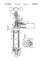
- FIG. 3 is a longitudinal section taken in the vertical plane through one of the barrels, the swing gate being lowered to lock the manifold in place, the gun being then operative in its injection mode;
- FIG. 4 is a longitudinal section taken through both barrels of the gun in the horizontal plane, the gun being then operative in its injection mode;
- FIG. 5 is a transverse section taken through FIG. 4;
- FIG. 6 is a longitudinal section taken in the vertical plane through one barrel of the gun, showing the gun at the conclusion of its injection mode of operation, the foil pack now being in a crushed state;
- FIG. 7 is a transverse section taken through the trigger and stop member sub-assembly of the gun, the ratchet pawl being shown in its operative position;
- FIG. 8 is the same as FIG. 7, but with the pawl retracted
- FIG. 9 is the same as FIG. 6, except now the swing gate is raised, the manifold is removed and the gun, which is now in its ejection mode, acts to eject the crushed foil pack from the barrel;
- FIG. 10 shows in section one preferred modification of the end cap
- FIG. 11 illustrates another modification of the end cap.
- an epoxy injection double-barreled gun in accordance with the invention is to inject a two-component structural epoxy into a hole formed in a substrate.
- the epoxy serves to anchor a threaded rod, a bolt, a reinforcing bar, a dowel or any other hardware element therein.
- the substrate may be solid concrete block, brick or stone, or any other form of masonry.
- the epoxy can be used to secure a screen tube in the masonry hole, and then to anchor a hardware element within the screen tube.
- the epoxy to be injected into the hole is constituted by a base resin component and a fast set or slow set hardener.
- the components are mixed in a 1 to 1 ratio to form the epoxy.
- These components are stored in sealed sausage-like, squeezable pouches or foil packs whose dimensions are such that they can be slidably received in the parallel barrels of the gun.
- the foil packs are preferably color coded for easy identification. Because of the 1 to 1 ratio, the foil packs are of the same size.
- a gun in accordance with the invention includes a pair of cylindrical barrels 10 and 11, preferably fabricated of aluminum, the barrels being in parallel relation.
- the trailing ends of the barrels are attached to a cast metal stock piece 12 having a grip 13 integral therewith.
- This grip is grasped by one hand of an operator whose other hand engages a crank handle 14 at the rear end of a lead screw 15.
- Screw 15 is included in the operating mechanism of the gun which is provided adjacent the grip with a trigger 16 and a retractable stop member 17. Thus the hand grasping the grip can manipulate the trigger with the thumb.
- the front end of lead screw 15 is received in a bearing 18 socketed in stock piece 12. Keyed to lead screw 15 adjacent bearing 18 is a ratchet wheel 19.
- stop member 17 when this member is in place is to cause the gun to then operate in an injection mode in which the components in the foil-pack loaded barrels are extruded and then intermixed to form the epoxy.
- the gun When the stop member is retracted, the gun is then operable in an ejection mode in which the foil packs, then in an exhausted and crushed state, are ejected from the barrels of the gun.
- each cap Slidably received through the leading ends of barrels 10 and 11 are sealed foil packs 20 and 21 having stored therein the two components of the epoxy to be injected.
- Manifold 25 includes a manifold pipe 32 communicating through stub pipes 33 and 34 with ports 29 and 31 in the caps.
- Manifold pipe 32 is provided at its midpoint with a projecting outlet or nipple 35.
- Nipple 35 is externally threaded to receive an elongated mixing nozzle 36 having a circuitous passage therein to effect mixing of the components passing through the nozzle.
- the gun In the injection mode, the gun is operate to slit open the front end of foil packs 20 and 21 loaded in the barrels and to extrude the gel-like components therefrom. As shown by the arrows in FIG. 4, the gels are forced into manifold pipe 32 and discharged through nipple 35 into mixing nozzle 36. The components are intermingled in the nozzle to form the epoxy which is then discharged.
- Manifold 25 which is removable from the barrel, is locked in place by means of a swing gate 37 (see FIG. 1) having a pair of parallel arms 38 and 39 whose rear ends are pivotally connected to opposite sides of stock piece 12. Secured to the front ends of these arms is a gate 40 which when the swing is lowered, as shown in FIG. 4, engages the exposed faces of caps 23 and 24. When the swing gate is thereafter raised, one may then withdraw the manifold 25 from the barrels.
- pistons 41 and 42 As shown in FIGS. 3 and 4, slidable in barrels 10 and 11 behind foil packs 20 and 21 are pistons 41 and 42. Pistons 41 and 42 are provided with piston rods 43 and 44 which extend from the trailing ends of barrels 10 and 11 through journals in stock piece 12 and terminate in a cross piece 45 bridging the rods.
- the operating mechanism for the gun which includes lead screw 15, acts to effect concurrent movement of pistons 41 and 42 to advance or retract the pistons.
- Lead screw 15 passes through a ball nut 46 mounted on cross piece 45 at a position intermediate piston rods 43 and 44.
- the nut is provided with ball bearings that are nested in the helical track of the screw and act to reduce friction between the screw and the nut.
- trigger 16 has a flat, horizontal portion 16A and a downwardly inclined finger portion. Stop member 17 overlies the flat portion of trigger 16.
- a pawl 49 whose lower end is slidably received in a hole in a shoulder 12S on stock piece 12, extends upwardly through openings in trigger 16 and plate-like stop member 17 to engage the teeth of ratchet wheel 19.
- the trigger is biased by a helical spring 47 surrounding the pawl, the spring being interposed between the undersurface of flat portion 16A of trigger 16 and the shoulder on stock piece 12.
- trigger 16 and stop member 17 fit loosely in a notch 48 formed in stock piece 12 so that they are free to swing downwardly.
- trigger 16 and stop member 17 then swing down against the pressure of spring 47.
- pawl 49 is disengaged from the teeth of ratchet wheel 19.
- FIG. 7 shows pawl 49 in engagement with the teeth of the wheel
- FIG. 8 shows the pawl retracted.
- crank handle 14 is turned clockwise by the operator, thereby causing both pistons to advance, and in doing so to force the front ends of the squeezable foil packs against cutting blades 28 and 30 in the rear of the caps.
- the front ends of the packs are slit open.
- Further advance of the pistons acts to compress the foil packs and bring about extrusion of the epoxy components from the packs into mixing manifold 25 where the components are intermingled and discharged as an epoxy from nozzle 36.
- the nozzle injects the epoxy into a substrate hole or wherever else the epoxy is to be applied as a bonding agent.
- the pistons continue to advance, the foil packs proceed to collapse, and when the packs are fully exhausted they are in a crushed state in the space between the caps and the pistons.
- stop member 17 which is in place in the injection mode of operation, acts to limit the advance of the pistons; for when cross piece 45 reaches and abuts the rear end of the plate-like stop member, no further advance of the pistons is then possible.
- the arrangement is such that the stop point of the pistons falls short of the cutting blades 28 and 30 to create a narrow accumulation space therebetween, so that the blades are not struck or injured by the pistons.
- the crushed and exhausted foil packs 20 and 21 then lie within is narrow accumulation space at the conclusion of the injection mode of operation.
- the gun is then operated in its ejection mode, which is illustrated in FIG. 9.
- swing gate 37 is lifted to unlock manifold 25 which is then removed from the gun barrels, thereby exposing the crushed, exhausted foil packs.
- Trigger 16 is then actuated, this action causing retraction of stop member 17, so that it now becomes possible to further advance the pistons to the leading end of the barrels, and in doing so to eject the crushed packs therefrom.
- foil pack ejection is that the operator need at no time touch the exhausted packs or use a tool of some sort to remove them from the barrels. Ejection takes place simply by a further advance of the pistons without soiling the hands of the operator or contaminating a pack-removing tool, or for that matter, the barrels of the gun.
- the invention is also applicable to a single barrel gun having the same features as a double-barreled gun; that is, a removable cap provided with a cutting blade or other means to slit open or penetrate the foil pack loaded in the barrel, and a retractable stop member which when the member and the cap are in place then operates in an injection mode, and when the cap is removed and the stop member is retracted, then operates in an ejection mode.
- the element or means by which a foil pack is slit open is constituted by a cutting blade.
- the invention is not limited to a cutting blade for this purpose, for the element may take the form of a spike, a post, or any other means capable of bursting, puncturing or slicing to create an opening in the foil pack when the pack is pressed against the element by the advancing piston.
- the stop means may be incorporated in the removable cap of the manifold rather than being combined with the trigger.
- the cap 50 which is fitted into the leading end of barrel 10 is provided at its rear with a triangular cutting blade 51 which is extended across the port in the cap.
- piston 41 is behind the foil pack loaded into the barrel and the foil pack is subjected to pressure by the advancing piston, the front end of the pack is forced against arcuate ledges 52 and 52.
- the piston pressure exerted on the pack causes the central zone at the front end of the pack which is bordered by the ledges to bulge out.
- This bulge which projects into the cap region encompassed by the ledges, is pierced by the apex of blade 51 which lies within this region, thereby slitting open the pack and causing extrusion of its contents as the piston continues to advance.
- the foil pack When the foil pack is in its crushed state, it then occupies the region surrounding ledges 52 and 52 as well as the inner cap region encompassed by the ledges. In the ejection mode of the gun, when cap 50 is removed, this acts to also remove ledges 52 and 52 which function as the stop member; hence now piston 41 is free to advance to the end of barrel 10 and thereby eject the crushed foil pack.
- a separate cutting blade is omitted, for cap 54, which is fitted into gun barrel 10, is provided at its rear with a well bordered by a pair of opposing prongs 55 and 56.
- These prongs act as stops to limit the advance of piston 41, and also as puncturing means.
- the prongs then penetrate the foil to produce openings in the pack from which the gel is extruded as the piston continues to advance during the injection mode of operation.
- the cap is removed from the barrel and the piston permitted to advance to the end of the barrel to eject the crushed pack therefrom.
- a circular array of prongs may be provided rather than a pair thereof.
Abstract
A double-barreled gun adapted to inject a two component epoxy into a hole to anchor a hardware element therein. The base resin and hardener components of the epoxy are stored in separate foil packs received in parallel barrels of the gun. The gun includes a removable mixing manifold having a pair of end caps which fit into the leading ends of the barrels and are joined to a manifold pipe to whose outlet is attachable a mixing nozzle. Mounted within the rear of each cap across a port therein is a cutting element. Slidable in each barrel behind the pack is a piston whose rod extends from the trailing end of the barrel. An operating mechanism effects concurrent advance of the pistons to an extent limited by a retractable stop member. In an injection mode of gun operation, the advancing pistons force the front ends of the packs against the cutting elements to slit open the packs, the advancing pistons then acting to extrude the components from the packs into the manifold from which the components pass into the mixing nozzle from which the epoxy is discharged. In this mode, the stop member limits advance of the pistons to a stop point short of the cutting elements, at which point the packs are in a crushed state. In an ejection mode, the manifold is removed and the stop member is retracted to permit the pistons to advance beyond the stop point and thereby eject the crushed packs from the barrels.
Description
This application is a continuation of my copending application Ser. No. 674 463, filed Mar. 25, 1991, of the same title, now U.S. Pat. No. 5,161,715 and whose entire disclosure is incorporated herein by reference.
1. Field of Invention
This invention relates generally to gun-type dispensers for discharging a viscous fluid or paste, such as a sealing or bonding agent, from a container storing this agent, and in particular to a double-barreled epoxy injection gun in which the two components of the epoxy are stored in separate foil packs that are loaded into the parallel barrels of the gun, the gun functioning to slit open the packs to permit extrusion and intermingling of the components to form the epoxy.
2. Status of Prior Art
Caulking is a putty-like plastic compound used for filling joints between masonry and other building materials, and for sealing cracks around window frames and wood and metal elements built into masonry joints. Caulking is usually applied by extruding it from a caulking gun to form a bead along the joint.
Caulking compounds and other pastes and viscous fluids which are to be dispensed from a gun are normally stored in a rigid cylinder having a sealed spout projecting from its forward end, the base of the cylinder being defined by a plunger. After the sealed spout is cut open, the plunger is advanced to subject the contents of the container to pressure, thereby causing the viscous fluid or paste to be extruded from the open spout.
Since it is necessary by means of a razor or scissor to cut open the spout, the viscous fluid in the container may then leak from the open spout and soil the hands of the operator as well as otherwise clean surfaces.
In order to provide a grease-dispensing gun adapted to be refilled and operated without soiling the hands of the operator, the Switzer U.S. Pat. No., 2,733,836, discloses a gun whose barrel is loaded with a sealed cylindrical cartridge containing grease. The Switzer gun includes at its forward end a piercing point that when the cartridge is subjected to pressure by a hand-operated plunger, punctures an opening in the cartridge.
In the Meyers et al. U.S. Pat. No. 3,130,872, the dispensing gun is adapted to discharge oils and other viscous fluid contained in sealed metal cans, and for this purpose, a spout is mounted on the front end of the gun, the spout having at its rear end a piercing point. When the can is pressed thereagainst by a hand-operated ram, the point punctures an opening therein into which the spout is inserted, so that the oil contends of the can may now be discharged.
In the dispensing gun shown in the Isgriggs et al. U.S. Pat. No. 3,193,146, a sealed can containing oil is loaded into the barrel of the gun whose forward end is provided with a slidable tap terminating in a piercing point. A removable plug received in the tap is struck a blow to cause the can to be pierced, after which the plug is removed to permit flow of the oil from the tap when pressure is applied to the can.
The concern of the present invention is not limited to gun-type dispensers for single component viscous fluids or pastes, for a need also exists for dispensers of two-component compounds such as an epoxy bonding agent in which one component is an epoxy resin and the other a hardener therefor. Separate packages are required for the components which are only intermixed when the epoxy is to be applied to a site to be bonded.
A problem which arises when the two components of an epoxy bonding agent are contained in separate squeeze tubes each having a sealed spout, is that if the same razor or other cutter is used to cut open both spouts, then the surface of the cutter may become smeared with both components which will interact and bond to this surface.
The Creighton et al. U.S. Pat. No. 3,323,682 discloses a gun-type dispenser in which two cartridges separately storing the resin and catalyst or hardener components of an epoxy bonding agent are concurrently subjected to pressure to extrude these components from the cartridges. As pointed out in this patent, should the resin and hardener components be accidentally mixed together in advance of their intended use, curing will then take place prematurely in a relatively short time, and the resultant epoxy would not be usable. It is essential, therefore, that the epoxy components be stored in separate sealed containers.
In the present invention, the viscous fluid paste to be dispensed is stored in a squeezable sealed pouch. Of prior art interest in regard to a pouch of this type is the Wainberg U.S. Pat. No., 4,265,372, in which oil or other viscous fluid is contained in a pouch formed of synthetic plastic material. This pouch is loaded into a dispenser-cutter which includes a blade that punctures a hole in the pouch which is then subjected to pressure to discharge the contents from the hole.
If one were to load a pouch of the Wainberg et al. type into the barrel of a dispensing gun and pierce an opening in the front end of the pouch, then when the pouch is subjected to pressure to extrude its contents, this will result in an exhausted pouch in a collapsed state at the front end of the barrel. And because the pouch in this state is crushed or crumpled, it is then more or less frictionally stuck within the barrel.
Yet in order to reload the barrel it is necessary to first pull out the crushed pouch therefrom. If an operator seeks to use his fingers for this purpose, he will not only experience difficulty in doing so, but he is likely to soil his fingers, for the surface of the collapsed pouch surrounding its pierced opening is smeared with the constituent it contained. Should he instead use a tweezer or other tool to extract the collapsed pouch from the barrel, the tool will become smeared. And if the gun has a pair of barrels, one for each component of an epoxy resin, since these components interact quickly, should the tool be smeared with both components, an epoxy will form and harden on the surface of the tool which will then be difficult to clean.
Also of prior art interest is the patent to Cannon et al., 3,767,085, showing a double barrel syringe having a common mixing chamber. Received in the barrels are cartridges containing the two constituents to be mixed, each cartridge having a rear plug which is engaged by a piston. The rods of the two pistons are joined by a common handle for concurrent advance of the pistons.
The main object of this invention is to provide a gun-type dispenser having a barrel adapted to accommodate a sausage-like squeezable pouch or foil pack storing a viscous fluid or paste such as a bonding agent, which dispenser, when actuated, functioning to first pierce an opening in the pouch through which its contents are then extruded.
A significant advantage of the invention is that the pouch or foil pack is sealed and leakproof and therefore suitable for long term storage of its contents. The pouch is not punctured until after it is loaded into the barrel of the dispensing gun and the gun then actuated,thereby avoiding soiling the hands of the operator and also obviating the need to cut open the pouch before it is loaded into the dispensing gun.
More particularly, an object of this invention is to provide a double-barreled dispensing gun in which each foil-pack loaded barrel has fitted into its leading end a detachable cap having at its rear a cutting element which is mounted across a port in the cap, the element acting when the pack is pressed thereagainst, to pierce an opening in the front end of the pack.
Also an object of this invention is to provide a gel or paste-dispensing gun whose barrel is loaded with a foil pack behind which is a slidable piston, the gun being operable in an injection mode in which as the piston advances it first acts to force the pack against a cutting blade in the rear of an end cap fitting into the leading end of the barrel to slit open the pack, and as the piston continues to advance, it then acts to extrude the paste through a port in the cap until the pack is exhausted and in a crushed state, the gun being thereafter operable in an ejection mode in which the cap is removed and further advance of the piston acts to eject the crushed pack from the barrel.
Yet another object of the invention is to provide a double-barreled dispensing gun whose parallel barrels are loaded with sealed foil packs storing the two components of an epoxy resin bonding agent, the barrels being coupled at their leading ends to a manifold to which a mixing nozzle is attachable, whereby the components extruded from the cut-open packs are fed into the mixing nozzle and are intermingled before being discharged.
Briefly stated, these objects are attained in a double-barreled gun adapted to inject a two component epoxy into a hole to anchor a hardware element therein. The base resin and hardener components of the epoxy are stored in separate foil packs received in the parallel barrels of the gun. The gun includes a removable mixing manifold having a pair of end caps which fit into the leading ends of the barrels and are joined to a manifold pipe to whose outlet is attachable a mixing nozzle. Mounted within the rear of each cap across a port therein is a cutting element. Slidable in each barrel behind the pack is a piston whose rod extends from the trailing end of the barrel.
An operating mechanism effects concurrent advance of the pistons to an extent limited by a retractable stop member. In an injection mode of gun operation, the advancing pistons force the packs against the cutting elements to slit open the front ends of the packs, these advancing pistons then acting to extrude the components from the packs into the manifold from which the components pass into the mixing nozzle from which the epoxy is discharged. In this mode, a stop member limits advance of the piston to a stop point short of the cutting elements, at which point the packs are in a crushed state. In an injection mode, the manifold assembly is removed to expose the leading ends of the barrels and the stop member is then retracted to permit the pistons to advance beyond the stop point to eject the crushed packs from the barrels.
For a better understanding of the invention as well as other objects and further features thereof, reference is made to the following detailed description to be read in conjunction with the accompanying drawings, wherein:
FIG. 1 is an exploded view of a double-barreled epoxy injection gun in accordance with the invention, the swing gate of which is raised to admit foil packs into the barrels;
FIG. 2 is a rear view of the manifold caps showing the cutting blades mounted therein;
FIG. 3 is a longitudinal section taken in the vertical plane through one of the barrels, the swing gate being lowered to lock the manifold in place, the gun being then operative in its injection mode;
FIG. 4 is a longitudinal section taken through both barrels of the gun in the horizontal plane, the gun being then operative in its injection mode;
FIG. 5 is a transverse section taken through FIG. 4;
FIG. 6 is a longitudinal section taken in the vertical plane through one barrel of the gun, showing the gun at the conclusion of its injection mode of operation, the foil pack now being in a crushed state;
FIG. 7 is a transverse section taken through the trigger and stop member sub-assembly of the gun, the ratchet pawl being shown in its operative position;
FIG. 8 is the same as FIG. 7, but with the pawl retracted;
FIG. 9 is the same as FIG. 6, except now the swing gate is raised, the manifold is removed and the gun, which is now in its ejection mode, acts to eject the crushed foil pack from the barrel;
FIG. 10 shows in section one preferred modification of the end cap; and
FIG. 11 illustrates another modification of the end cap.
The purpose of an epoxy injection double-barreled gun in accordance with the invention is to inject a two-component structural epoxy into a hole formed in a substrate. The epoxy serves to anchor a threaded rod, a bolt, a reinforcing bar, a dowel or any other hardware element therein. The substrate may be solid concrete block, brick or stone, or any other form of masonry. In the case of hollow masonry, the epoxy can be used to secure a screen tube in the masonry hole, and then to anchor a hardware element within the screen tube.
The epoxy to be injected into the hole is constituted by a base resin component and a fast set or slow set hardener. The components are mixed in a 1 to 1 ratio to form the epoxy. These components are stored in sealed sausage-like, squeezable pouches or foil packs whose dimensions are such that they can be slidably received in the parallel barrels of the gun.
The foil packs are preferably color coded for easy identification. Because of the 1 to 1 ratio, the foil packs are of the same size.
As shown in FIGS. 1 to 4, a gun in accordance with the invention includes a pair of cylindrical barrels 10 and 11, preferably fabricated of aluminum, the barrels being in parallel relation. The trailing ends of the barrels are attached to a cast metal stock piece 12 having a grip 13 integral therewith. This grip is grasped by one hand of an operator whose other hand engages a crank handle 14 at the rear end of a lead screw 15. Screw 15 is included in the operating mechanism of the gun which is provided adjacent the grip with a trigger 16 and a retractable stop member 17. Thus the hand grasping the grip can manipulate the trigger with the thumb. The front end of lead screw 15 is received in a bearing 18 socketed in stock piece 12. Keyed to lead screw 15 adjacent bearing 18 is a ratchet wheel 19.
The function of stop member 17 when this member is in place is to cause the gun to then operate in an injection mode in which the components in the foil-pack loaded barrels are extruded and then intermixed to form the epoxy. When the stop member is retracted, the gun is then operable in an ejection mode in which the foil packs, then in an exhausted and crushed state, are ejected from the barrels of the gun.
Slidably received through the leading ends of barrels 10 and 11 are sealed foil packs 20 and 21 having stored therein the two components of the epoxy to be injected. Fitting into the leading ends of barrels 10 and 11 are the end caps 23 and 24 of a mixing manifold 25 which, as best seen in FIG. 4, are provided with elastomeric O-rings 26 and 27. Mounted within a well in the rear of each cap, as shown in FIG. 2, is a metal cutting blade having a triangular profile, blade 28 being disposed across a central port 29 in cap 23 and blade 30 across a central port 31 in cap 24. The blades function to slit open the foil packs so that when the packs are squeezed or compressed, the components are extruded therefrom to pass through the ports of the cap.
In the injection mode, the gun is operate to slit open the front end of foil packs 20 and 21 loaded in the barrels and to extrude the gel-like components therefrom. As shown by the arrows in FIG. 4, the gels are forced into manifold pipe 32 and discharged through nipple 35 into mixing nozzle 36. The components are intermingled in the nozzle to form the epoxy which is then discharged.
As shown in FIGS. 3 and 4, slidable in barrels 10 and 11 behind foil packs 20 and 21 are pistons 41 and 42. Pistons 41 and 42 are provided with piston rods 43 and 44 which extend from the trailing ends of barrels 10 and 11 through journals in stock piece 12 and terminate in a cross piece 45 bridging the rods.
The operating mechanism for the gun, which includes lead screw 15, acts to effect concurrent movement of pistons 41 and 42 to advance or retract the pistons. Lead screw 15 passes through a ball nut 46 mounted on cross piece 45 at a position intermediate piston rods 43 and 44. The nut is provided with ball bearings that are nested in the helical track of the screw and act to reduce friction between the screw and the nut.
When an operator grasping grip 13 in one hand and crank handle 14 in the other hand, turns screw 15 clockwise, this causes the pistons to concurrently advance in the barrels of the gun. When screw 15 is turned counterclockwise, the pistons are then retracted.
As shown in FIGS. 6, 7 and 8, trigger 16 has a flat, horizontal portion 16A and a downwardly inclined finger portion. Stop member 17 overlies the flat portion of trigger 16. A pawl 49, whose lower end is slidably received in a hole in a shoulder 12S on stock piece 12, extends upwardly through openings in trigger 16 and plate-like stop member 17 to engage the teeth of ratchet wheel 19. The trigger is biased by a helical spring 47 surrounding the pawl, the spring being interposed between the undersurface of flat portion 16A of trigger 16 and the shoulder on stock piece 12.
The front ends of trigger 16 and stop member 17 fit loosely in a notch 48 formed in stock piece 12 so that they are free to swing downwardly. When trigger 16 is actuated by a finger of the operator whose hand grasps grip 13, trigger 16 and stop member 17 then swing down against the pressure of spring 47. In doing so, pawl 49 is disengaged from the teeth of ratchet wheel 19. Thus FIG. 7 shows pawl 49 in engagement with the teeth of the wheel, and FIG. 8 shows the pawl retracted.
When pawl 49 engages the teeth of ratchet wheel 9 keyed to lead screw 15, it then permits unidirectional clockwise motion of the screw to advance cross piece 45 and thereby cause concurrent advance of the pistons in the barrels of the gun. Counterclockwise motion is then prevented by the ratchet. However, when pawl 49 is disengaged from the ratchet wheel, then screw 15 can be turned counterclockwise to retract the pistons. Before the barrels can be loaded with the foil packs, the pistons must be retracted to make room for the packs.
In the injection mode of gun operation, as shown in FIG. 4, barrels 10 and 11 are loaded with sealed foil packs 20 and 21, and caps 23 and 24 of the manifold 25 are fitted into the leading ends of the barrels and are locked in place by gate 40 of the swing gate which is now closed. Trigger 16 is unactuated; hence stop member 17 is in place.
In this mode of operation, crank handle 14 is turned clockwise by the operator, thereby causing both pistons to advance, and in doing so to force the front ends of the squeezable foil packs against cutting blades 28 and 30 in the rear of the caps. As a consequence, the front ends of the packs are slit open. Further advance of the pistons acts to compress the foil packs and bring about extrusion of the epoxy components from the packs into mixing manifold 25 where the components are intermingled and discharged as an epoxy from nozzle 36. The nozzle injects the epoxy into a substrate hole or wherever else the epoxy is to be applied as a bonding agent. As the pistons continue to advance, the foil packs proceed to collapse, and when the packs are fully exhausted they are in a crushed state in the space between the caps and the pistons.
As shown in FIG. 6, stop member 17, which is in place in the injection mode of operation, acts to limit the advance of the pistons; for when cross piece 45 reaches and abuts the rear end of the plate-like stop member, no further advance of the pistons is then possible. The arrangement is such that the stop point of the pistons falls short of the cutting blades 28 and 30 to create a narrow accumulation space therebetween, so that the blades are not struck or injured by the pistons. The crushed and exhausted foil packs 20 and 21 then lie within is narrow accumulation space at the conclusion of the injection mode of operation.
In order now to eject the crushed and exhausted foil packs from the barrels of the gun so that these barrels may be reloaded with fresh packs, the gun is then operated in its ejection mode, which is illustrated in FIG. 9. In this mode, swing gate 37 is lifted to unlock manifold 25 which is then removed from the gun barrels, thereby exposing the crushed, exhausted foil packs.
The advantage of such foil pack ejection is that the operator need at no time touch the exhausted packs or use a tool of some sort to remove them from the barrels. Ejection takes place simply by a further advance of the pistons without soiling the hands of the operator or contaminating a pack-removing tool, or for that matter, the barrels of the gun.
While there has been disclosed a double-barreled gun, the invention is also applicable to a single barrel gun having the same features as a double-barreled gun; that is, a removable cap provided with a cutting blade or other means to slit open or penetrate the foil pack loaded in the barrel, and a retractable stop member which when the member and the cap are in place then operates in an injection mode, and when the cap is removed and the stop member is retracted, then operates in an ejection mode.
In the gun shown in FIGS. 1 to 9, the element or means by which a foil pack is slit open is constituted by a cutting blade. However, the invention is not limited to a cutting blade for this purpose, for the element may take the form of a spike, a post, or any other means capable of bursting, puncturing or slicing to create an opening in the foil pack when the pack is pressed against the element by the advancing piston.
And while a retractable stop member is provided to prevent the advancing piston from striking and possibly damaging the cutting element when the gun is operated in its injection mode, the stop means may be incorporated in the removable cap of the manifold rather than being combined with the trigger. Thus in the embodiment of the removable manifold shown in FIG. 10, the cap 50 which is fitted into the leading end of barrel 10 is provided at its rear with a triangular cutting blade 51 which is extended across the port in the cap.
Surrounding blade 51 is an opposing pair of arcuate ledges 52 and 53 whose height somewhat exceeds that of the apex of the triangular blade 51, the curvature of the ledges conforming to that of barrel 10. Hence the advance of piston 41 in barrel 10 is arrested when the piston abuts ledges 52 and 52. The piston cannot therefore strike the apex of the blade.
However, since piston 41 is behind the foil pack loaded into the barrel and the foil pack is subjected to pressure by the advancing piston, the front end of the pack is forced against arcuate ledges 52 and 52. The piston pressure exerted on the pack causes the central zone at the front end of the pack which is bordered by the ledges to bulge out. This bulge, which projects into the cap region encompassed by the ledges, is pierced by the apex of blade 51 which lies within this region, thereby slitting open the pack and causing extrusion of its contents as the piston continues to advance.
When the foil pack is in its crushed state, it then occupies the region surrounding ledges 52 and 52 as well as the inner cap region encompassed by the ledges. In the ejection mode of the gun, when cap 50 is removed, this acts to also remove ledges 52 and 52 which function as the stop member; hence now piston 41 is free to advance to the end of barrel 10 and thereby eject the crushed foil pack.
In the cap arrangement shown in FIG. 11, a separate cutting blade is omitted, for cap 54, which is fitted into gun barrel 10, is provided at its rear with a well bordered by a pair of opposing prongs 55 and 56. These prongs act as stops to limit the advance of piston 41, and also as puncturing means. Thus when the foil pack is pressed against the prongs by the piston, the prongs then penetrate the foil to produce openings in the pack from which the gel is extruded as the piston continues to advance during the injection mode of operation. In the ejection mode, the cap is removed from the barrel and the piston permitted to advance to the end of the barrel to eject the crushed pack therefrom. In practice, a circular array of prongs may be provided rather than a pair thereof.
While there has been shown and described a preferred embodiment of a double-barreled epoxy injection gun in accordance with the invention, it will be appreciated that many changes and modifications may be made therein without, however, departing from the essential spirit thereof.
Claims (5)
1. A gun for dispensing a viscous agent stored in a sealed, sausage-like, crushable foil pouch, said gun comprising:
(a) at least one cylindrical barrel having a leading end and a trailing end, said barrel being loadable with the pouch through the leading end thereof, whereby a front foil portion of the pouch is then adjacent the leading end;
(b) a removable cap fitting the leading end of the barrel to retain the pouch therein, said cap being provided with a central port and a rear section;
(c) a blade adjacent the rear section of the cap across said port and facing the front foil portion of the pouch;
(d) a piston slidable in the barrel behind the pouch and provided with a rod extending from the trailing end of the barrel; and
(e) an operating mechanism coupled to said piston rod, said mechanism, when the cap is fitted on the leading end of the barrel, acting to first advance the piston to force the front foil portion of the pouch against the blade to create an opening therein, and to then advance the piston to extrude the agent from the pouch through said cap port, and in doing so to crush the foil pouch until the agent is exhausted therefrom and the foil pouch is then in a crushed state at a position adjacent the leading end of the barrel.
2. A gun set forth in claim 1 wherein said blade is in triangular form and has an apex that lies on an axis passing through the port, whereby when the front portion of the pouch is forced against the apex, it cuts an opening therein from which the agent is extruded from the pouch and enters said port.
3. A gun as set forth in claim 2, wherein the rear section of the cap is provided with an abutment whose height exceeds that of the apex of the blade, whereby the piston advancing in the barrel is arrested when it engages said abutment and the piston therefore cannot strike the apex.
4. A gun as set forth in claim 3, wherein said abutment is constituted by at least one ledge.
5. A gun as set forth in claim 3, wherein said abutment is constituted by a pair of arcuate ledges at opposite ends of the blade in the rear section of the cap, the curvature of the ledges conforming to that of the barrel, piston pressure on the pouch causing its front end portion bordered by the ledges to bulge out to project into a region encompassed by the ledges where it is pierced by the apex of the blade which lies in this region.
Priority Applications (1)
| Application Number | Priority Date | Filing Date | Title |
|---|---|---|---|
| US07/885,748 US5242082A (en) | 1991-03-25 | 1992-05-19 | Double-barreled epoxy injection gun |
Applications Claiming Priority (2)
| Application Number | Priority Date | Filing Date | Title |
|---|---|---|---|
| US07/674,463 US5161715A (en) | 1991-03-25 | 1991-03-25 | Double-barreled epoxy injection gun |
| US07/885,748 US5242082A (en) | 1991-03-25 | 1992-05-19 | Double-barreled epoxy injection gun |
Related Parent Applications (1)
| Application Number | Title | Priority Date | Filing Date |
|---|---|---|---|
| US07/674,463 Continuation US5161715A (en) | 1991-03-25 | 1991-03-25 | Double-barreled epoxy injection gun |
Publications (1)
| Publication Number | Publication Date |
|---|---|
| US5242082A true US5242082A (en) | 1993-09-07 |
Family
ID=24706705
Family Applications (3)
| Application Number | Title | Priority Date | Filing Date |
|---|---|---|---|
| US07/674,463 Expired - Fee Related US5161715A (en) | 1991-03-25 | 1991-03-25 | Double-barreled epoxy injection gun |
| US07/712,590 Expired - Fee Related US5184757A (en) | 1991-03-25 | 1991-06-10 | Double-barreled epoxy injection gun |
| US07/885,748 Expired - Fee Related US5242082A (en) | 1991-03-25 | 1992-05-19 | Double-barreled epoxy injection gun |
Family Applications Before (2)
| Application Number | Title | Priority Date | Filing Date |
|---|---|---|---|
| US07/674,463 Expired - Fee Related US5161715A (en) | 1991-03-25 | 1991-03-25 | Double-barreled epoxy injection gun |
| US07/712,590 Expired - Fee Related US5184757A (en) | 1991-03-25 | 1991-06-10 | Double-barreled epoxy injection gun |
Country Status (1)
| Country | Link |
|---|---|
| US (3) | US5161715A (en) |
Cited By (42)
| Publication number | Priority date | Publication date | Assignee | Title |
|---|---|---|---|---|
| US5386928A (en) * | 1993-11-15 | 1995-02-07 | Minnesota Mining And Manufacturing Company | Dual collapsible tube dispensing assembly |
| DE19806869A1 (en) * | 1998-02-19 | 1999-08-26 | Focke & Co | Adhesive applicator used for producing packaging, especially cigarette packets |
| US5993188A (en) * | 1997-11-19 | 1999-11-30 | Mak; King Biu | Food extruding device |
| US6352177B1 (en) * | 1998-10-14 | 2002-03-05 | Kettenbach Gmbh & Co. Kg | Device for discharging a pasty two-component mixture |
| US6464112B2 (en) | 1999-09-09 | 2002-10-15 | Sashco, Inc. | Dispensing cartridges having collapsible packages for use in caulking guns |
| US20030132541A1 (en) * | 2002-01-16 | 2003-07-17 | Dov Zamonski | Method and device for repairing a tire |
| US6612465B2 (en) * | 2000-10-13 | 2003-09-02 | Dentsply Research & Development Corp. | Multi-component mixing storage and dispensing device |
| US6681957B1 (en) | 2002-07-17 | 2004-01-27 | Ronald D. Green | Collapsible dispensing system |
| US20040178225A1 (en) * | 2001-02-15 | 2004-09-16 | Hosokawa Yoko Co., Ltd. | Cartridge for fluid material and dispensing apparatus for such a cartridge |
| US20040204715A1 (en) * | 2001-02-12 | 2004-10-14 | Evans Avery J. | Multi-use surgical cement dispenser apparatus and kit for same |
| US20050198927A1 (en) * | 1999-09-09 | 2005-09-15 | Elliot Summons | Method of filling dispensing cartridges having collapsible packages |
| US20060165020A1 (en) * | 2004-11-24 | 2006-07-27 | Allen Schultz | Audio conference system |
| US20070164047A1 (en) * | 2003-08-14 | 2007-07-19 | 3M Innovative Properties Company | Capsule for two-component materials |
| US20080121656A1 (en) * | 2006-08-29 | 2008-05-29 | Devirag Francis Kiss | Spreadable food dispenser for two or more foods |
| US20080123465A1 (en) * | 2005-01-26 | 2008-05-29 | Rolf Heusser | Multicomponent Foil-Type Container |
| US20090023132A1 (en) * | 2005-03-31 | 2009-01-22 | C2 Diagnostics | Hydraulic device for a blood analysis apparatus, associated method and analysis apparatus equipped with such a device |
| US20090298010A1 (en) * | 2006-03-09 | 2009-12-03 | Broyles Bruce R | Device for dispensing material |
| US7811291B2 (en) | 2007-11-16 | 2010-10-12 | Osseon Therapeutics, Inc. | Closed vertebroplasty bone cement injection system |
| US20110017771A1 (en) * | 2009-07-23 | 2011-01-27 | Manfred Obrsit | Apparatus for the storage and metering of a plurality of components |
| US20110017775A1 (en) * | 2009-07-23 | 2011-01-27 | Manfred Obrist | Apparatus for the storage and metering of a plurality of components |
| USD657876S1 (en) | 2010-02-02 | 2012-04-17 | 3M Innovative Properties Company | Dental capsule |
| US20120279988A1 (en) * | 2011-05-02 | 2012-11-08 | Sulzer Mixpac Ag | Mixer for mixing at least two flowable components and dispensing apparatus |
| US20120295215A1 (en) * | 2009-11-20 | 2012-11-22 | Emir Jelovac | Device for dispensing a material |
| WO2013078514A1 (en) * | 2011-11-30 | 2013-06-06 | Imdex Limited | Grout delivery |
| CN103269806A (en) * | 2010-12-24 | 2013-08-28 | Sika技术股份公司 | Metering and mixing device for multi-component substances |
| US8727185B2 (en) * | 2012-01-04 | 2014-05-20 | GM Ergonomics, LLC | Dispenser device and system |
| US8814738B2 (en) | 2009-11-20 | 2014-08-26 | 3M Innovative Properties Company | Device for dispensing a dental composition |
| US8827981B2 (en) | 2007-11-16 | 2014-09-09 | Osseon Llc | Steerable vertebroplasty system with cavity creation element |
| TWI495492B (en) * | 2014-03-27 | 2015-08-11 | Taiwan Biomaterial Co Ltd | Syringe |
| US9205970B2 (en) | 2010-12-24 | 2015-12-08 | Sika Technology Ag | Application device for multi-component substances, a cartridge set and a packaging unit |
| CN105710009A (en) * | 2016-04-01 | 2016-06-29 | 叶秀 | Novel sealant applying device |
| US9439446B2 (en) | 2010-07-16 | 2016-09-13 | Mcgill Technology Limited | Dispensing apparatus |
| US9510885B2 (en) | 2007-11-16 | 2016-12-06 | Osseon Llc | Steerable and curvable cavity creation system |
| US10463380B2 (en) | 2016-12-09 | 2019-11-05 | Dfine, Inc. | Medical devices for treating hard tissues and related methods |
| US10478241B2 (en) | 2016-10-27 | 2019-11-19 | Merit Medical Systems, Inc. | Articulating osteotome with cement delivery channel |
| US10562064B2 (en) | 2014-09-23 | 2020-02-18 | Sika Technology Ag | Head plate device, storage container device, cartridge arrangement, dispensing apparatus, and their usage |
| US10624652B2 (en) | 2010-04-29 | 2020-04-21 | Dfine, Inc. | System for use in treatment of vertebral fractures |
| US10660656B2 (en) | 2017-01-06 | 2020-05-26 | Dfine, Inc. | Osteotome with a distal portion for simultaneous advancement and articulation |
| US11026744B2 (en) | 2016-11-28 | 2021-06-08 | Dfine, Inc. | Tumor ablation devices and related methods |
| US11197681B2 (en) | 2009-05-20 | 2021-12-14 | Merit Medical Systems, Inc. | Steerable curvable vertebroplasty drill |
| US11510723B2 (en) | 2018-11-08 | 2022-11-29 | Dfine, Inc. | Tumor ablation device and related systems and methods |
| US11523669B2 (en) * | 2017-06-23 | 2022-12-13 | Seb S.A. | Production apparatus for producing a composition |
Families Citing this family (102)
| Publication number | Priority date | Publication date | Assignee | Title |
|---|---|---|---|---|
| GB9024916D0 (en) * | 1990-11-16 | 1991-01-02 | Du Pont Canada | Improved pouch dispenser |
| DE59203897D1 (en) * | 1991-11-18 | 1995-11-09 | Wilhelm A Keller | Safety flap for securing a discharge cartridge on a hand discharge device. |
| DE4208451A1 (en) * | 1992-03-17 | 1993-09-23 | Ara Werk Kraemer Gmbh & Co | DISCHARGE DEVICE FOR PASTOESE MEASURES |
| US5263614A (en) * | 1992-05-14 | 1993-11-23 | Jacobsen Kenneth H | Material dispensing tool for tubular cartridges |
| GB9213852D0 (en) * | 1992-06-30 | 1992-08-12 | Dow Corning Gmbh | Sealant cartridge |
| US5301835A (en) * | 1992-09-17 | 1994-04-12 | Dow Corning Corporation | Adapter for dispensing material from a sausage type package |
| US5443181A (en) * | 1992-09-19 | 1995-08-22 | Hilti Aktiengesellschaft | Cartridge and piston for dispensing mass |
| US5421484A (en) * | 1993-07-07 | 1995-06-06 | Polar Express International, Inc. | Frozen dessert dispensing apparatus |
| GB9401439D0 (en) * | 1994-01-26 | 1994-03-23 | Ciba Geigy Ag | Apparatus |
| BE1008472A3 (en) * | 1994-07-05 | 1996-05-07 | Mertens De Wilmars Antoon | Packaging for two-constituent adhesives and device for the application ofsaid adhesives |
| US5551606A (en) * | 1994-07-14 | 1996-09-03 | Rai; Charn | Dispenser |
| US5566860A (en) * | 1994-09-08 | 1996-10-22 | Liquid Control Corporation | Dual component cartridge |
| US5535922A (en) * | 1994-11-29 | 1996-07-16 | Tah Industries, Inc. | Caulking gun dispensing module for multi-component cartridge |
| DE29501255U1 (en) * | 1995-01-27 | 1995-03-09 | Hilti Ag | Foil bag pack with foil bag and bottom part |
| US5699935A (en) * | 1996-01-18 | 1997-12-23 | The Procter & Gamble Company | Inverting bag co-dispenser |
| US5893486A (en) * | 1997-05-27 | 1999-04-13 | Liquid Control Corporation | Foam dispensing device |
| DE69833513T2 (en) * | 1998-03-03 | 2006-08-24 | Sicpa Holding S.A. | Housing containing a replaceable flexible packaging unit |
| JP2002523221A (en) * | 1998-08-24 | 2002-07-30 | ロックタイト コーポレーション | Single stroke fluid metering device |
| WO2000027747A1 (en) * | 1998-11-10 | 2000-05-18 | Jempac International Corporation | Chemical cartridge handling and dispensing mechanism |
| DE50001283D1 (en) * | 1999-06-15 | 2003-03-27 | Createchnic Ag Nuerensdorf | DISPOSABLE SELF-OPENER TO OPEN A TUBE CARTRIDGE AND EXPRESS A PASTE DIMENSION FROM THE SAME |
| US6223941B1 (en) | 1999-07-19 | 2001-05-01 | The Boeing Company | Applicator for dispensing a soft package of material |
| US6290428B1 (en) * | 1999-09-21 | 2001-09-18 | Allen M. Hall | Machine and method for dispensing a sealing compound |
| US6533189B2 (en) * | 1999-12-14 | 2003-03-18 | Vortex Sprayliners, Inc. | Method and apparatus for spraying truck bed liners |
| US6578737B2 (en) * | 2001-07-23 | 2003-06-17 | Paul D. Jackman | Pressure activated self-opening cartridge nozzle |
| US20030136859A1 (en) * | 2002-01-18 | 2003-07-24 | 3M Innovative Properties Company | Method of applying two-component pavement markings and apparatus |
| DE10204776C1 (en) * | 2002-02-05 | 2003-07-17 | Jens Bauer | Pipeline sealing method has different components of sealing material supplied from respective deformable supply containers upon supplying pressure medium to rigid pressure cell |
| US6733252B2 (en) * | 2002-05-10 | 2004-05-11 | Fqubed | Fluid-handling systems and components comprising a bladder pump, a methods therefor |
| SE519974C2 (en) * | 2002-06-03 | 2003-05-06 | Cemvac System Ab | Device for dispensing a monomer to a polymer-filled mixing device for preparing bone cement |
| GB0304351D0 (en) * | 2003-02-26 | 2003-04-02 | Wood Bruce M | Chemical dispensing means |
| US7105113B2 (en) * | 2003-07-11 | 2006-09-12 | Urethane International Llc | Method for flatproofing a tire and wheel assembly and resulting flatproofed assembly |
| US7066724B2 (en) * | 2003-07-11 | 2006-06-27 | Urethane International Llc | Apparatus for flatproofing a tire and wheel assembly |
| DE10360627B4 (en) * | 2003-12-19 | 2006-02-23 | Heraeus Kulzer Gmbh | Multi-component cartridge and its application |
| US7784423B1 (en) * | 2004-04-28 | 2010-08-31 | National Semiconductor Corporation | System and method for dispensing material onto a semiconductor wafer |
| EP1602342A1 (en) * | 2004-06-04 | 2005-12-07 | 3M Espe AG | Locking assembly and dispensing cartridge comprising the same |
| US20100108709A1 (en) | 2004-12-30 | 2010-05-06 | Plas-Pak Industries | Cartridge delivery system utilizing film bags |
| US9517488B2 (en) | 2004-12-30 | 2016-12-13 | Plas-Pak Industries, Inc. | Component delivery system utilizing film bags |
| DE102005002850B4 (en) * | 2005-01-20 | 2009-09-17 | Kettenbach Gmbh & Co. Kg | Device for storing and discharging fluid substances |
| US7690530B2 (en) * | 2005-05-06 | 2010-04-06 | Albion Engineering Company | Dispenser for viscous material |
| US20060272108A1 (en) * | 2005-06-06 | 2006-12-07 | Ruth Stern | Method to apply a hair care preparation and kit for same |
| EA012817B1 (en) * | 2005-09-03 | 2009-12-30 | Артекс-Ролплаг Лимитед | Cartridge dispenser |
| EP1795145B1 (en) * | 2005-12-06 | 2008-09-10 | 3M Innovative Properties Company | Dispensing cartridge with grip |
| US20070289996A1 (en) * | 2006-06-19 | 2007-12-20 | Todd Alan Wheatcraft | Polyurethane and epoxy adhesive applicator systems |
| JP4855171B2 (en) * | 2006-07-28 | 2012-01-18 | キユーピー株式会社 | Gun type dispenser for viscous liquids |
| SE530703C2 (en) * | 2006-12-22 | 2008-08-19 | Asept Int Ab | Device for dispensing and dispensing means for such device |
| GB0707573D0 (en) * | 2007-04-19 | 2007-05-30 | 3M Innovative Properties Co | Dispensing device with locking member |
| US8146604B2 (en) * | 2007-05-14 | 2012-04-03 | Angles Beauty | Fluid delivery device |
| DE102007000838A1 (en) * | 2007-10-09 | 2009-04-16 | Hilti Aktiengesellschaft | squeezing |
| CN101428266B (en) * | 2007-11-05 | 2012-04-25 | 苏州宝时得电动工具有限公司 | Driving mechanism of glue gun |
| US20090131950A1 (en) * | 2007-11-16 | 2009-05-21 | Liu Y King | Vertebroplasty method with enhanced control |
| US20090299282A1 (en) * | 2007-11-16 | 2009-12-03 | Osseon Therapeutics, Inc. | Steerable vertebroplasty system with a plurality of cavity creation elements |
| WO2009073209A1 (en) * | 2007-12-06 | 2009-06-11 | Osseon Therapeutics, Inc. | Vertebroplasty implant with enhanced interfacial shear strength |
| US20090193915A1 (en) * | 2008-02-01 | 2009-08-06 | Feng-Ho Wang | Separable ball screw |
| US8197122B2 (en) * | 2008-04-24 | 2012-06-12 | Tyco Healthcare Group Lp | Dynamic mixing applicator |
| CH699115A1 (en) * | 2008-07-14 | 2010-01-15 | Medmix Systems Ag | A dispensing assembly with a cartridge bag. |
| EP2396237B1 (en) * | 2009-02-13 | 2014-11-19 | Medmix Systems AG | Discharge device with tube |
| GB0902354D0 (en) | 2009-02-13 | 2009-04-01 | 3M Innovative Properties Co | Syringes for dispensing multicomponent material |
| CA2666080A1 (en) * | 2009-05-14 | 2010-11-14 | Colour Revolution Inc. | Applicator |
| US8584907B2 (en) * | 2009-09-09 | 2013-11-19 | Albion Engineering Co. | Power tool including moveable remote trigger |
| US20110079607A1 (en) * | 2009-10-06 | 2011-04-07 | Consolidated Edison Company Of New York, Inc. | Sealant system |
| DE102009049285A1 (en) * | 2009-10-13 | 2011-05-05 | Heraeus Kulzer Gmbh | One-pack for dental mixing device |
| CH703427A1 (en) * | 2010-07-12 | 2012-01-13 | Medmix Systems Ag | Kartuschendispenser with twist lock. |
| IL207715A0 (en) | 2010-08-19 | 2010-12-30 | Omrix Biopharmaceuticals | Device for administering fluids and use thereof |
| CN203578058U (en) | 2010-11-15 | 2014-05-07 | 密尔沃基电动工具公司 | Powered dispensing tool |
| WO2012068092A2 (en) | 2010-11-15 | 2012-05-24 | Milwaukee Electric Tool Corporation | Powered dispensing tool |
| DE102011056608B4 (en) * | 2010-12-23 | 2015-08-27 | CAS Chemotechnische Abpack-Service- GmbH | Mixing and cartridge filling device |
| USD679810S1 (en) * | 2011-03-28 | 2013-04-09 | 3M Innovative Properties Company | Dental syringe |
| US8857672B2 (en) | 2011-06-20 | 2014-10-14 | Milwaukee Electric Tool Corporation | Carriage assembly for dispensing tool |
| US9039557B2 (en) | 2011-09-02 | 2015-05-26 | Milwaukee Electric Tool Corporation | Powered dispensing tool |
| US20130277391A1 (en) * | 2011-09-27 | 2013-10-24 | Adco Products, Inc. | Adhesive package |
| US9579686B2 (en) | 2012-10-29 | 2017-02-28 | Nordson Corporation | Fluid dispensing assemblies and methods of dispensing fluids from containers |
| JP6293421B2 (en) * | 2013-04-08 | 2018-03-14 | 旭化成株式会社 | Discharge jig for film pack |
| US9782735B2 (en) * | 2013-06-12 | 2017-10-10 | Daniel ORTIZ GARCIA | Device for mixing and applying a compound produced by mixing two products |
| US9527106B2 (en) | 2013-10-31 | 2016-12-27 | Nordson Corporation | Applicator and method for dispensing a viscous fluid |
| US9821512B2 (en) | 2014-04-10 | 2017-11-21 | Dow Global Technologies Llc | Method and apparatus for dispensing reactive two-part systems |
| US20170225191A1 (en) * | 2014-08-19 | 2017-08-10 | Medmix Systems Ag | Rotary dispenser for multiple cartridge |
| FR3028563A1 (en) * | 2014-11-13 | 2016-05-20 | Frederic Lecaplain | ALTERNATIVE PISTON AND CONTAINER COMPRISING THERMAL, PNEUMATIC, HYBRID AND PNEUMATIC ENERGY RECOVERY |
| KR101635524B1 (en) * | 2014-11-13 | 2016-07-04 | 정열 | Multiple layer driving gear type paste discharge container |
| EP3025744A1 (en) | 2014-11-28 | 2016-06-01 | Sulzer Mixpac AG | Apparatus and methods for storing and mixing separate substances |
| JP6828232B2 (en) * | 2015-03-13 | 2021-02-10 | セメダイン株式会社 | Extrusion mechanism |
| US10166570B1 (en) * | 2015-04-15 | 2019-01-01 | Patent & Investment Llc | Applicator system for extrusive dispensing of work material from collapsible cartridge |
| EP3429761A4 (en) * | 2016-03-16 | 2019-11-27 | Henkel AG & Co. KGaA | Battery powered dispenser for one and two component foils and cartridges |
| CN105728281A (en) * | 2016-04-01 | 2016-07-06 | 邱焕玲 | Durable and portable cement extruding device |
| CN105855143A (en) * | 2016-04-01 | 2016-08-17 | 邱焕玲 | Convenient cementing device |
| CN105728283A (en) * | 2016-04-01 | 2016-07-06 | 邱焕玲 | Steady and durable cement extruding device |
| CN105710008A (en) * | 2016-04-01 | 2016-06-29 | 邱焕玲 | Durable sealant applying device |
| CN105728280A (en) * | 2016-04-01 | 2016-07-06 | 邱焕玲 | Novel cement extruding device convenient to use |
| WO2017194844A1 (en) * | 2016-05-10 | 2017-11-16 | Lecaplain Frédéric | Reciprocating container piston functioning as a hybrid pneumatic heat engine and as a pneumatic energy recovery device |
| EP3263483A1 (en) | 2016-07-01 | 2018-01-03 | Sulzer Mixpac AG | Cartridge, core, mold and method of manufacturing a cartridge |
| EP3263482B1 (en) | 2016-07-01 | 2018-09-19 | Sulzer Mixpac AG | Cartridge, core, mold and method of manufacturing a cartridge |
| US20180056324A1 (en) | 2016-08-31 | 2018-03-01 | Nordson Corporation | Multi-component flexible pack dispensing manifold and system |
| US10766053B2 (en) | 2017-01-04 | 2020-09-08 | Red Devil, Inc. | Material dispensing system and method |
| US10596591B2 (en) * | 2017-01-04 | 2020-03-24 | Red Devil Inc. | Material dispensing system and method |
| US10106393B1 (en) * | 2017-04-19 | 2018-10-23 | Winter Creek Designs | Beverage dispensing system |
| US10906702B2 (en) | 2018-10-02 | 2021-02-02 | Sulzer Mixpac Ag | Cartridge, method of manufacturing a cartridge, dispensing assembly and method of assembling a dispensing assembly |
| EP3632575A1 (en) * | 2018-10-02 | 2020-04-08 | Sulzer Mixpac AG | Reusable cartridge piston |
| US10870127B2 (en) | 2018-10-02 | 2020-12-22 | Sulzer Mixpac Ag | Cartridge for a mixing and dispensing system |
| WO2020069784A1 (en) | 2018-10-02 | 2020-04-09 | Sulzer Mixpac Ag | Cartridge, method of manufacturing a cartridge, dispensing assembly and method of assembling a dispensing assembly |
| CN209362907U (en) * | 2018-11-08 | 2019-09-10 | 昆山瀚元电子科技有限公司 | A kind of glue rifle |
| US10780455B1 (en) * | 2019-01-29 | 2020-09-22 | Yona Heilbruner | Caulking gun |
| US11654453B1 (en) * | 2019-07-09 | 2023-05-23 | Jacob Burns | Roof coating applicator |
| CN110918401B (en) * | 2019-12-22 | 2021-07-09 | 东莞市朝发皮具有限公司 | Anti-blocking glue spraying equipment |
| DK180911B1 (en) * | 2020-12-09 | 2022-06-23 | Onrobot As | Dispenser tool and robot with such tool |
Citations (6)
| Publication number | Priority date | Publication date | Assignee | Title |
|---|---|---|---|---|
| US1965271A (en) * | 1930-03-17 | 1934-07-03 | Frederick M Durkee | Grease gun and the like |
| US3077078A (en) * | 1959-10-13 | 1963-02-12 | Thompson Ramo Wooldridge Inc | Injector chamber construction |
| US4067479A (en) * | 1975-07-31 | 1978-01-10 | Products Research & Chemical Corporation | Two part material meter-mix dispenser apparatus |
| US4136801A (en) * | 1977-12-09 | 1979-01-30 | Stanford Pavenick | Replaceable cartridge for a dispenser |
| GB2088998A (en) * | 1980-12-04 | 1982-06-16 | Toray Silicone Co | Caulking Gun |
| US5104005A (en) * | 1988-11-10 | 1992-04-14 | Albion Engineering Company | Dual component mechanically operated caulking gun |
Family Cites Families (35)
| Publication number | Priority date | Publication date | Assignee | Title |
|---|---|---|---|---|
| US2733836A (en) * | 1956-02-07 | Perforator and container for packaged grease | ||
| US2090644A (en) * | 1933-07-15 | 1937-08-24 | Fred B Seeberger | Calking gun |
| US2105039A (en) * | 1935-05-29 | 1938-01-11 | Kendall Refining Company | Method and apparatus for dispensing grease, oil, and the like, and can therefor |
| US2131487A (en) * | 1936-11-16 | 1938-09-27 | Lubrication Corp | Cartridge for lubricants or the like |
| US2139143A (en) * | 1937-03-27 | 1938-12-06 | Norman N Wiswell | Collapsing container and collapsing device |
| GB572665A (en) * | 1941-04-30 | 1945-10-18 | British United Shoe Machinery | Improvements in or relating to apparatus for delivering fluent material |
| US2421711A (en) * | 1944-09-27 | 1947-06-03 | Battenfeld Grease Oil | Extruding applicator for calking compound cartridges |
| GB825409A (en) * | 1957-07-16 | 1959-12-16 | Secomastic Ltd | Improvements relating to extrusion guns |
| US3117696A (en) * | 1961-07-12 | 1964-01-14 | Cyril J Herman | Gun for two component adhesives |
| US3130872A (en) * | 1962-02-06 | 1964-04-28 | R C Can Co | Device for discharging viscous fluid |
| US3193146A (en) * | 1962-10-08 | 1965-07-06 | R C Can Co | Dispensing gun |
| DE1486405A1 (en) * | 1965-04-15 | 1969-06-04 | H V Hardman Company Inc | Device for mixing and dispensing materials |
| US3439839A (en) * | 1965-09-16 | 1969-04-22 | Prod Res & Chem Corp | Sealant dispensing device |
| US3323682A (en) * | 1965-10-06 | 1967-06-06 | Chem Dev Corp | Disposable cartridge for gun-type dispensers |
| US3401847A (en) * | 1967-04-03 | 1968-09-17 | Thermon Mfg Co | Pneumatically powered applicator |
| US3595448A (en) * | 1967-08-18 | 1971-07-27 | Ewell Lee Carlton | Sealant dispensers |
| US3504826A (en) * | 1968-05-16 | 1970-04-07 | Ewell Lee Carlton | Sealant containers and dispensers |
| GB1205210A (en) * | 1969-04-16 | 1970-09-16 | Ford Motor Co | Dispenser for multi-component adhesives |
| US3767085A (en) * | 1971-08-02 | 1973-10-23 | J Cannon | Mixing syringe |
| US3938709A (en) * | 1972-04-24 | 1976-02-17 | Techon Systems, Inc. | Gas pressure actuated plastic squeeze dispenser and valving means therefor |
| US3831815A (en) * | 1972-11-09 | 1974-08-27 | Glasgow Prod Inc | Dental wax extruder |
| AT332102B (en) * | 1973-10-03 | 1976-09-10 | Fischbach A Kunststoff Kg | HOLLOW CYLINDRICAL EXTRUDED VESSEL |
| US4260076A (en) * | 1979-09-14 | 1981-04-07 | Whirlco, Inc. | Powered dispenser for caulking cartridge contents |
| DE2949369A1 (en) * | 1979-12-07 | 1981-06-11 | Hilti AG, 9494 Schaan | DEVICE FOR DELIVERING MULTI-COMPONENT DIMENSIONS |
| EP0039245A1 (en) * | 1980-04-30 | 1981-11-04 | Black & Decker | Cartridge assembly |
| US4376498A (en) * | 1980-10-02 | 1983-03-15 | Davis George B Jun | Hand-held pneumatic caulking gun |
| GB2090336B (en) * | 1980-12-29 | 1984-08-01 | Toray Silicone Co | Caulking gun using bagged sealer |
| EP0261466B1 (en) * | 1986-09-14 | 1990-07-25 | Wilhelm A. Keller | Double discharge cartridge for two-component compounds |
| DE3705741A1 (en) * | 1987-02-23 | 1988-09-01 | Hilti Ag | DISPENSING DEVICE FOR FLOWABLE MEASURES |
| US5033650A (en) * | 1987-03-09 | 1991-07-23 | Laurence Colin | Multiple barrel dispensing device |
| US4869400A (en) * | 1988-02-29 | 1989-09-26 | Richard Jacobs | Composition dispensing system |
| ES2029752T3 (en) * | 1988-07-13 | 1992-09-01 | Gurit-Essex Ag | PROCEDURE FOR THE EXPULSION OF A SUBSTANCE CONTAINED IN A CARTRIDGE AND DEVICE FOR CARRYING OUT THE PROCEDURE. |
| US4907727A (en) * | 1988-10-31 | 1990-03-13 | Illinois Tool Works, Inc. | Dispensing device having improved plunger assemblies |
| FR2646790B1 (en) * | 1989-05-09 | 1991-10-04 | Corso Dominique | IMPROVEMENTS ON PISTOLS FOR THE EXTRUSION OF PASTY PRODUCTS |
| US4974756A (en) * | 1989-07-14 | 1990-12-04 | Minnesota Mining And Manufacturing Company | Double barrel dispensing container and cap therefor |
-
1991
- 1991-03-25 US US07/674,463 patent/US5161715A/en not_active Expired - Fee Related
- 1991-06-10 US US07/712,590 patent/US5184757A/en not_active Expired - Fee Related
-
1992
- 1992-05-19 US US07/885,748 patent/US5242082A/en not_active Expired - Fee Related
Patent Citations (6)
| Publication number | Priority date | Publication date | Assignee | Title |
|---|---|---|---|---|
| US1965271A (en) * | 1930-03-17 | 1934-07-03 | Frederick M Durkee | Grease gun and the like |
| US3077078A (en) * | 1959-10-13 | 1963-02-12 | Thompson Ramo Wooldridge Inc | Injector chamber construction |
| US4067479A (en) * | 1975-07-31 | 1978-01-10 | Products Research & Chemical Corporation | Two part material meter-mix dispenser apparatus |
| US4136801A (en) * | 1977-12-09 | 1979-01-30 | Stanford Pavenick | Replaceable cartridge for a dispenser |
| GB2088998A (en) * | 1980-12-04 | 1982-06-16 | Toray Silicone Co | Caulking Gun |
| US5104005A (en) * | 1988-11-10 | 1992-04-14 | Albion Engineering Company | Dual component mechanically operated caulking gun |
Cited By (69)
| Publication number | Priority date | Publication date | Assignee | Title |
|---|---|---|---|---|
| US5386928A (en) * | 1993-11-15 | 1995-02-07 | Minnesota Mining And Manufacturing Company | Dual collapsible tube dispensing assembly |
| US5993188A (en) * | 1997-11-19 | 1999-11-30 | Mak; King Biu | Food extruding device |
| DE19806869A1 (en) * | 1998-02-19 | 1999-08-26 | Focke & Co | Adhesive applicator used for producing packaging, especially cigarette packets |
| US6352177B1 (en) * | 1998-10-14 | 2002-03-05 | Kettenbach Gmbh & Co. Kg | Device for discharging a pasty two-component mixture |
| US20050198927A1 (en) * | 1999-09-09 | 2005-09-15 | Elliot Summons | Method of filling dispensing cartridges having collapsible packages |
| US6464112B2 (en) | 1999-09-09 | 2002-10-15 | Sashco, Inc. | Dispensing cartridges having collapsible packages for use in caulking guns |
| US20020162859A1 (en) * | 1999-09-09 | 2002-11-07 | Summons Wayne L. | Method of filling dispensing cartridges having collapsible packages |
| US7194847B2 (en) | 1999-09-09 | 2007-03-27 | Sashco, Inc. | Method of filling dispensing cartridges having collapsible packages |
| US6612465B2 (en) * | 2000-10-13 | 2003-09-02 | Dentsply Research & Development Corp. | Multi-component mixing storage and dispensing device |
| US20100094307A1 (en) * | 2001-02-12 | 2010-04-15 | Evans Avery J | Multi-use surgical cement dispenser apparatus and kit for same |
| US20040204715A1 (en) * | 2001-02-12 | 2004-10-14 | Evans Avery J. | Multi-use surgical cement dispenser apparatus and kit for same |
| US8506572B2 (en) | 2001-02-12 | 2013-08-13 | Carefusion 2200, Inc. | Multi-use surgical cement dispenser apparatus and kit for same |
| US7371241B2 (en) | 2001-02-12 | 2008-05-13 | Modmed Therapeutics, Inc. | Multi-use surgical cement dispenser apparatus and kit for same |
| US20040178225A1 (en) * | 2001-02-15 | 2004-09-16 | Hosokawa Yoko Co., Ltd. | Cartridge for fluid material and dispensing apparatus for such a cartridge |
| US20030132541A1 (en) * | 2002-01-16 | 2003-07-17 | Dov Zamonski | Method and device for repairing a tire |
| US6681957B1 (en) | 2002-07-17 | 2004-01-27 | Ronald D. Green | Collapsible dispensing system |
| US7882983B2 (en) * | 2003-08-14 | 2011-02-08 | 3M Innovative Properties Company | Capsule for two-component materials |
| US8561845B2 (en) | 2003-08-14 | 2013-10-22 | 3M Innovative Properties Company | Capsule for two-component materials |
| US20110084094A1 (en) * | 2003-08-14 | 2011-04-14 | 3M Innovative Properties Company | Capsule for two-component materials |
| US20070164047A1 (en) * | 2003-08-14 | 2007-07-19 | 3M Innovative Properties Company | Capsule for two-component materials |
| US20060165020A1 (en) * | 2004-11-24 | 2006-07-27 | Allen Schultz | Audio conference system |
| US7934864B2 (en) * | 2005-01-26 | 2011-05-03 | Sulzer Mixpac Ag | Multicomponent foil-type container |
| US20080123465A1 (en) * | 2005-01-26 | 2008-05-29 | Rolf Heusser | Multicomponent Foil-Type Container |
| US20090023132A1 (en) * | 2005-03-31 | 2009-01-22 | C2 Diagnostics | Hydraulic device for a blood analysis apparatus, associated method and analysis apparatus equipped with such a device |
| US20090298010A1 (en) * | 2006-03-09 | 2009-12-03 | Broyles Bruce R | Device for dispensing material |
| US9211168B2 (en) | 2006-03-09 | 2015-12-15 | 3M Innovative Properties Company | Device for dispensing material |
| US8328553B2 (en) | 2006-03-09 | 2012-12-11 | 3M Innovative Properties Company | Device for dispensing material |
| US20080121656A1 (en) * | 2006-08-29 | 2008-05-29 | Devirag Francis Kiss | Spreadable food dispenser for two or more foods |
| US8827981B2 (en) | 2007-11-16 | 2014-09-09 | Osseon Llc | Steerable vertebroplasty system with cavity creation element |
| US7842041B2 (en) | 2007-11-16 | 2010-11-30 | Osseon Therapeutics, Inc. | Steerable vertebroplasty system |
| US7811291B2 (en) | 2007-11-16 | 2010-10-12 | Osseon Therapeutics, Inc. | Closed vertebroplasty bone cement injection system |
| US9510885B2 (en) | 2007-11-16 | 2016-12-06 | Osseon Llc | Steerable and curvable cavity creation system |
| US11197681B2 (en) | 2009-05-20 | 2021-12-14 | Merit Medical Systems, Inc. | Steerable curvable vertebroplasty drill |
| US20110017775A1 (en) * | 2009-07-23 | 2011-01-27 | Manfred Obrist | Apparatus for the storage and metering of a plurality of components |
| US9321577B2 (en) * | 2009-07-23 | 2016-04-26 | Sulzer Mixpac Ag | Apparatus for the storage and metering of a plurality of components |
| US20110017771A1 (en) * | 2009-07-23 | 2011-01-27 | Manfred Obrsit | Apparatus for the storage and metering of a plurality of components |
| US20120295215A1 (en) * | 2009-11-20 | 2012-11-22 | Emir Jelovac | Device for dispensing a material |
| US8814738B2 (en) | 2009-11-20 | 2014-08-26 | 3M Innovative Properties Company | Device for dispensing a dental composition |
| USD658763S1 (en) | 2010-02-02 | 2012-05-01 | 3M Innovative Properties Company | Dental capsule |
| USD657876S1 (en) | 2010-02-02 | 2012-04-17 | 3M Innovative Properties Company | Dental capsule |
| US10624652B2 (en) | 2010-04-29 | 2020-04-21 | Dfine, Inc. | System for use in treatment of vertebral fractures |
| US9439446B2 (en) | 2010-07-16 | 2016-09-13 | Mcgill Technology Limited | Dispensing apparatus |
| US9737084B2 (en) | 2010-07-16 | 2017-08-22 | Mcgill Technology Limited | Dispensing apparatus |
| CN103269806B (en) * | 2010-12-24 | 2016-02-24 | Sika技术股份公司 | For metering and the mixing arrangement of multi-component material |
| US9205970B2 (en) | 2010-12-24 | 2015-12-08 | Sika Technology Ag | Application device for multi-component substances, a cartridge set and a packaging unit |
| US9242784B2 (en) * | 2010-12-24 | 2016-01-26 | Sika Technology Ag | Metering and mixing device for multi-component substances |
| US20130277390A1 (en) * | 2010-12-24 | 2013-10-24 | Sika Technology Ag | Metering and mixing device for multi-component substances |
| CN103269806A (en) * | 2010-12-24 | 2013-08-28 | Sika技术股份公司 | Metering and mixing device for multi-component substances |
| US9149775B2 (en) * | 2011-05-02 | 2015-10-06 | Sulzer Mixpac Ag | Mixer for mixing at least two flowable components and dispensing apparatus |
| AU2012202426B2 (en) * | 2011-05-02 | 2014-06-26 | Sulzer Mixpac Ag | Mixer for mixing at least two flowable components and dispensing apparatus |
| US20120279988A1 (en) * | 2011-05-02 | 2012-11-08 | Sulzer Mixpac Ag | Mixer for mixing at least two flowable components and dispensing apparatus |
| AU2012318278B2 (en) * | 2011-11-30 | 2015-09-17 | Imdex Limited | Grout delivery |
| WO2013078514A1 (en) * | 2011-11-30 | 2013-06-06 | Imdex Limited | Grout delivery |
| US8727185B2 (en) * | 2012-01-04 | 2014-05-20 | GM Ergonomics, LLC | Dispenser device and system |
| TWI495492B (en) * | 2014-03-27 | 2015-08-11 | Taiwan Biomaterial Co Ltd | Syringe |
| US10562064B2 (en) | 2014-09-23 | 2020-02-18 | Sika Technology Ag | Head plate device, storage container device, cartridge arrangement, dispensing apparatus, and their usage |
| CN105710009A (en) * | 2016-04-01 | 2016-06-29 | 叶秀 | Novel sealant applying device |
| US10478241B2 (en) | 2016-10-27 | 2019-11-19 | Merit Medical Systems, Inc. | Articulating osteotome with cement delivery channel |
| US11344350B2 (en) | 2016-10-27 | 2022-05-31 | Dfine, Inc. | Articulating osteotome with cement delivery channel and method of use |
| US11026744B2 (en) | 2016-11-28 | 2021-06-08 | Dfine, Inc. | Tumor ablation devices and related methods |
| US11116570B2 (en) | 2016-11-28 | 2021-09-14 | Dfine, Inc. | Tumor ablation devices and related methods |
| US10470781B2 (en) | 2016-12-09 | 2019-11-12 | Dfine, Inc. | Medical devices for treating hard tissues and related methods |
| US10463380B2 (en) | 2016-12-09 | 2019-11-05 | Dfine, Inc. | Medical devices for treating hard tissues and related methods |
| US11540842B2 (en) | 2016-12-09 | 2023-01-03 | Dfine, Inc. | Medical devices for treating hard tissues and related methods |
| US10660656B2 (en) | 2017-01-06 | 2020-05-26 | Dfine, Inc. | Osteotome with a distal portion for simultaneous advancement and articulation |
| US11607230B2 (en) | 2017-01-06 | 2023-03-21 | Dfine, Inc. | Osteotome with a distal portion for simultaneous advancement and articulation |
| US11523669B2 (en) * | 2017-06-23 | 2022-12-13 | Seb S.A. | Production apparatus for producing a composition |
| US11510723B2 (en) | 2018-11-08 | 2022-11-29 | Dfine, Inc. | Tumor ablation device and related systems and methods |
| US11937864B2 (en) | 2018-11-08 | 2024-03-26 | Dfine, Inc. | Ablation systems with parameter-based modulation and related devices and methods |
Also Published As
| Publication number | Publication date |
|---|---|
| US5184757A (en) | 1993-02-09 |
| US5161715A (en) | 1992-11-10 |
Similar Documents
| Publication | Publication Date | Title |
|---|---|---|
| US5242082A (en) | Double-barreled epoxy injection gun | |
| JP5984357B2 (en) | Multi-component discharge cartridge and method provided with parallel fluid chambers | |
| US4340154A (en) | Caulker for dispensing two viscous components | |
| US4371094A (en) | Barrier two part pairing and dispensing cartridge | |
| US3390814A (en) | Mixing device | |
| US5263614A (en) | Material dispensing tool for tubular cartridges | |
| EP0624403B1 (en) | Dual product dispenser | |
| US20080011784A1 (en) | Dispenser for viscous material | |
| US4969747A (en) | Reverse flow dispensing mixer | |
| DE102017110732B4 (en) | Apparatus for producing a bone cement dough and for discharging the mixed bone cement dough, and a method for producing a bone cement dough | |
| US4019654A (en) | Manual cartridge dispenser | |
| EP0693437A1 (en) | A cartridge with an exchangeable content package | |
| US3730394A (en) | Putty mixing container for caulking gun-type dispenser | |
| US3188057A (en) | Apparatus for mixing and dispensing multi-component materials | |
| EP1651358B1 (en) | Device for the expression or dosed application of a free-flowing paste-like substance | |
| US3933273A (en) | Dispenser for expelling contents of collapsible tubes and method of using | |
| DE2949368A1 (en) | DEVICE FOR DELIVERING ONE OR MULTI-COMPONENT DIMENSIONS | |
| EP0721805A2 (en) | Apparatus for mixing and dispensing of moulding material | |
| JPS59230563A (en) | Syringe | |
| US5560521A (en) | Recyclable caulk cartridge with breakaway nozzle | |
| EP0093185A1 (en) | Caulker for dispensing two viscous components | |
| DE102007060382B4 (en) | Slicing device for opening a tubular bag | |
| US6089412A (en) | Multipurpose dispenser system | |
| JP2003516911A (en) | Folding dispenser | |
| DE4327755C2 (en) | Cartridge for two-component compounds |
Legal Events
| Date | Code | Title | Description |
|---|---|---|---|
| REMI | Maintenance fee reminder mailed | ||
| LAPS | Lapse for failure to pay maintenance fees | ||
| FP | Lapsed due to failure to pay maintenance fee |
Effective date: 19970910 |
|
| STCH | Information on status: patent discontinuation |
Free format text: PATENT EXPIRED DUE TO NONPAYMENT OF MAINTENANCE FEES UNDER 37 CFR 1.362 |