US5240071A - Improved valve assembly apparatus using travelling isolation pipe - Google Patents
Improved valve assembly apparatus using travelling isolation pipe Download PDFInfo
- Publication number
- US5240071A US5240071A US07/911,983 US91198392A US5240071A US 5240071 A US5240071 A US 5240071A US 91198392 A US91198392 A US 91198392A US 5240071 A US5240071 A US 5240071A
- Authority
- US
- United States
- Prior art keywords
- assembly
- tubing
- production
- valve assembly
- valve
- Prior art date
- Legal status (The legal status is an assumption and is not a legal conclusion. Google has not performed a legal analysis and makes no representation as to the accuracy of the status listed.)
- Expired - Lifetime
Links
- 238000002955 isolation Methods 0.000 title claims abstract description 44
- 238000004519 manufacturing process Methods 0.000 claims abstract description 105
- 238000007789 sealing Methods 0.000 claims abstract description 14
- 230000015572 biosynthetic process Effects 0.000 claims description 23
- 239000002002 slurry Substances 0.000 claims description 6
- 238000012856 packing Methods 0.000 abstract description 6
- 239000012530 fluid Substances 0.000 description 18
- 238000005755 formation reaction Methods 0.000 description 18
- 239000004576 sand Substances 0.000 description 12
- 238000000034 method Methods 0.000 description 9
- 229930195733 hydrocarbon Natural products 0.000 description 7
- 150000002430 hydrocarbons Chemical class 0.000 description 7
- 230000008569 process Effects 0.000 description 6
- 239000004215 Carbon black (E152) Substances 0.000 description 3
- 239000011521 glass Substances 0.000 description 3
- 239000000463 material Substances 0.000 description 3
- 125000006850 spacer group Chemical group 0.000 description 3
- 238000005086 pumping Methods 0.000 description 2
- 238000011084 recovery Methods 0.000 description 2
- 230000000712 assembly Effects 0.000 description 1
- 238000000429 assembly Methods 0.000 description 1
- 238000004140 cleaning Methods 0.000 description 1
- 239000002131 composite material Substances 0.000 description 1
- 238000010276 construction Methods 0.000 description 1
- 238000005553 drilling Methods 0.000 description 1
- 230000009977 dual effect Effects 0.000 description 1
- 230000000694 effects Effects 0.000 description 1
- 230000008570 general process Effects 0.000 description 1
- 238000010348 incorporation Methods 0.000 description 1
- 238000002347 injection Methods 0.000 description 1
- 239000007924 injection Substances 0.000 description 1
- 230000002452 interceptive effect Effects 0.000 description 1
- 238000012986 modification Methods 0.000 description 1
- 230000004048 modification Effects 0.000 description 1
- 230000002028 premature Effects 0.000 description 1
- 239000007787 solid Substances 0.000 description 1
- 238000012360 testing method Methods 0.000 description 1
Images


Classifications
-
- E—FIXED CONSTRUCTIONS
- E21—EARTH DRILLING; MINING
- E21B—EARTH DRILLING, e.g. DEEP DRILLING; OBTAINING OIL, GAS, WATER, SOLUBLE OR MELTABLE MATERIALS OR A SLURRY OF MINERALS FROM WELLS
- E21B34/00—Valve arrangements for boreholes or wells
- E21B34/06—Valve arrangements for boreholes or wells in wells
- E21B34/14—Valve arrangements for boreholes or wells in wells operated by movement of tools, e.g. sleeve valves operated by pistons or wire line tools
-
- E—FIXED CONSTRUCTIONS
- E21—EARTH DRILLING; MINING
- E21B—EARTH DRILLING, e.g. DEEP DRILLING; OBTAINING OIL, GAS, WATER, SOLUBLE OR MELTABLE MATERIALS OR A SLURRY OF MINERALS FROM WELLS
- E21B34/00—Valve arrangements for boreholes or wells
- E21B34/06—Valve arrangements for boreholes or wells in wells
- E21B34/063—Valve or closure with destructible element, e.g. frangible disc
-
- E—FIXED CONSTRUCTIONS
- E21—EARTH DRILLING; MINING
- E21B—EARTH DRILLING, e.g. DEEP DRILLING; OBTAINING OIL, GAS, WATER, SOLUBLE OR MELTABLE MATERIALS OR A SLURRY OF MINERALS FROM WELLS
- E21B34/00—Valve arrangements for boreholes or wells
- E21B34/06—Valve arrangements for boreholes or wells in wells
- E21B34/10—Valve arrangements for boreholes or wells in wells operated by control fluid supplied from outside the borehole
-
- E—FIXED CONSTRUCTIONS
- E21—EARTH DRILLING; MINING
- E21B—EARTH DRILLING, e.g. DEEP DRILLING; OBTAINING OIL, GAS, WATER, SOLUBLE OR MELTABLE MATERIALS OR A SLURRY OF MINERALS FROM WELLS
- E21B43/00—Methods or apparatus for obtaining oil, gas, water, soluble or meltable materials or a slurry of minerals from wells
- E21B43/02—Subsoil filtering
- E21B43/04—Gravelling of wells
- E21B43/045—Crossover tools
Definitions
- the apparatus of the present invention relates to downhole valves. More particularly, the present invention relates to a disc valve, constructed of a breakable material, such as glass, positioned in the flow bore of a tubing string that prevents flow of fluid through the bore from either direction. When flow is desired, the breakable disc is ruptured, and the flow is allowed to commence within the bore.
- the disc valve assembly would be sheared free from the wash pipe and pushed to a position below the telltale screen so that the opening for production would be substantially larger than with the first embodiment.
- an isolation pipe would be engaged to the wash pipe for isolating the formation for production to commence. It is this particular embodiment which is the focus of this application.
- an exterior casing In the general process for drilling and production of oil and gas wells, at that point in the process where a hydrocarbon formation has been located at a particular depth, normally an exterior casing would be lowered down the bore hole through the area of production, known as the production zone.
- the exterior casing is perforated with the use of a perforating gun or the like.
- a permanent type packer referred to as a "sump packer” is usually set below the perforations.
- an internal tubing string together with sand screen and blank pipe, packer and packer extension, hydraulic setting tool, cross-over tool, and wash pipe, are positioned within the exterior casing to engage with the "sump packer".
- the annulus between the sand screen and the exterior perforated casing is packed off, utilizing certain procedures. This packing off is necessary so that the interior tubing would be utilized to carry the recovered hydrocarbons to the surface.
- the area around the perforations is prepared, so that the flow of hydrocarbons may commence.
- the well must be gravel packed, so that the flow of sand or the like out of the formation is prevented during recovery of the hydrocarbons.
- the present invention would be utilized following the gravel packing procedure, with the assignee company, Completion Services, Inc., would designate as the "Complete Gravel Pack," which would include a hydraulic setting tool and crossover being run into the well with the required sand screen and blank pipe.
- the packer assembly would be seated using pump pressure applied to the tubing. After it is seated, the crossover valve may be opened and closed. With the crossover valve closed, the packer may be pressure tested by pumping down the casing. Fluid may be pumped into the formation to establish injection rate. Also, the formation may be acidized, if necessary. With the crossover valve open, sand slurry may be circulated to place sand outside of the screen and into the formation until adequate gravel pack is obtained. After removal of the setting tool and crossover, a production seal assembly is run in for production of the zone.
- the well may not necessarily be pressure balanced.
- the formation under these conditions, may tend to absorb the well fluid into the production zone or the fluid in the zone may tend to flow into the well. In either case, this could lead to unacceptable (a) loss of expensive well fluid, (b) damage to the formation, (c) danger of a potential well blow-out or co-mingling of formation fluids.
- a flapper valve can be utilized which would hold pressure in one direction only. However, flapper valves can be easily damaged, activated premature, leak or rupture at too low a pressure differential.
- the apparatus of the present invention solves the problems in the art in a simple and straightforward manner.
- a length of tubing longer than the production screen, positioned at the end of a wash pipe and lowered into the tubing bore so that the lower end of the tubing is a depth below the production screen.
- the tubing is then placed in position by raising the wash pipe and tubing to the upper seal bore.
- the wash pipe is then sheared from the tubing assembly.
- the tubing includes seals at each end, which seat in respective seal bores, for sealing off above and below the production screen.
- a valving mechanism such as a sliding door valve which is operable from the surface between open and closed positions. While the valving mechanism is closed, the production flow is prevented; however, upon opening the valve with a wire line shifting tool, production flows through the sliding door valve and up to the surface through the tubing.
- FIGS. 1A through 1G illustrated cross-section views of isolated components making up the upper and lower sections of the lower circulation configuration utilizing the present invention
- FIG. 1H is an overall view of the components of the assembly as illustrated in FIGS. 1A through 1G, including the components in the tubing string situation directly above the assembly components that are illustrated in FIG. 1H;
- FIGS. 2A through 2D illustrate in cross-section views, the isolated components of the assembly during upper circulation following the raising of the top seal ring out of sealing engagement with the bottom seal bore;
- FIGS. 2E through 2G illustrate in cross-section views, the isolated components of the assembly further illustrating the upper section of the assembly after the wash pipe has been sheared and withdrawn from borehole and the disc valve is locked in position;
- FIG. 3 illustrates a cross-section view of the manner in which the travelling disc valve of the present invention is ruptured and removed to allow flow as illustrated in FIGS. 4A and 4B;
- FIGS. 4A and 4B illustrate cross-section views of isolated components of the system utilizing the present invention, with the disc valve ruptured to allow production flow in the system;
- FIGS. 5 through 7 illustrate cross-section overall views of the original embodiment of the travelling disc valve apparatus in the upper circulating position, the position of the disc valve locked in place, and the position when the well is producing, respectively;
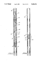
- FIGS. 8 through 10 illustrate cross-section overall views of the embodiment of the travelling isolation pipe valving apparatus in the upper circulating position, the position of the isolation pipe sealing off the production zone, and the position when the well is producing, respectively;
- FIG. 11 illustrates a cross-sectional overall view of an additional embodiment of the travelling isolation pipe sealing off from the production zone within the casing.
- FIG. 12 illustrates in cross-sectional overall view the additional embodiment of the travelling isolation pipe whereby a mechanical perforator has been lowered down a wire line and is perforated the wall of the isolation pipe to allow production to commence through the perforated wall.
- FIGS. 1A through 1G The apparatus of the present invention referred to as a travelling disc valve is illustrated in the figures by the numeral 10.
- the entire assembly housing the travelling disc valve assembly during lower circulation is shown in FIGS. 1A through 1G.
- the upper 1D section of the assembly is illustrated in FIGS. 1A through 1D, and the lower section of the assembly illustrated in FIGS. 1E through 1G.
- FIG. 1H there is illustrated an overall composite view of the disc valve assembly as seen in its isolated components in FIGS. 1A through 1G, and the components in the tubing string positioned directly above the disc valve assembly. These would comprise upper setting tool and crossover assembly 114, with the compset packer 116 positioned directly below. Furthermore, there is illustrated the perforated extension 118, which is attached directly to the seal bore 120, which is positioned directly below the perforated extension 118. Furthermore, there is illustrated the indicator collet 122, and the no-go housing 124 for the disc valve 10. Directly below the no-go housing for the disc valve is a seal bore 126 for the disc valve 10, and thence the production screen 32 as illustrated in the isolated views, the top seal bore member 30, and thence the disc valve assembly 10 as will be discussed further.
- travelling disc valve 10 comprises a solid piece of material, preferably glass, which may be of various thicknesses depending on the pressures downhole that may be encountered and various diameters depending on the size of the tubing in which the disc valve 10 is positioned.
- Disc 10 is positioned within a groove 12 in the wall of a collet member 14, as illustrated in FIG. 1G.
- Groove 12 is formed on its lower end by a circular end piece 18 threadably secured on the lower end of collet 14 which serves as the lower shoulder upon which the disc valve 10 rests in groove 12.
- FIGS. 1A-1G comprise a series of isolated views of the system, extending from the upper packer extension 20 down to the lower most component, the sump packer 22.
- the packer extension 20 is threadably engaged to a top locator 24 which engages on its lowermost end a collet locator 26.
- the collet locator 26 interconnects to an elongated spacer 28, which, at its lower end engages the top seal bore member 30, to which bank tubing and the production screen 32 is suspended.
- Production screen 32 as illustrated in FIG. 1E would be a typical production screen having an outer screen layer 33, positioned around the screen support wall 33A.
- the support wall 33A would include a plurality of ports 33B so that production flow through the ports 35 in the wall of the production casing 36 into the annulus 37 of the production casing 36, would flow into the internal bore of the production screen and up to the surface as will be described further.
- FIGS. 1D and 1E when production is commenced the hydrocarbon flow would move through the perforations in the wall of casing 36, into the annulus between the wall of casing 36 and the production screen 32, and then to the surface through the bore in the production string.
- the lower end of production screen 32 would be connected to a bottom seal bore 40, for connecting to, at its lower end 41, a second screen, or a telltale screen 44, which would be connected to a bottom locator 50 and then to the lowest component, the sump packer 22, which would pack off the lowest most point of the assembly so that fluid or production flow could not pass that point during production.
- outer production assembly 100 further comprise a continuous internal bore 54 therethrough, in which there is housed the internal system for carrying the travelling disc valve 10, and will be referred to as the travelling disc valve assembly 102.
- the assembly 102 would comprise an upper length of wash pipe 58 extending down the internal bore 54 of the outer assembly 100, and would extend and interconnect to a shear joint 56 the lower end of which would interconnect to a collet 57.
- the collet 57 would further include a first top seal ring 60 which would form a seal between the outer wall 59 of collet 57 and the inner wall of bottom seal bore member 40, to prevent fluid flow therebetween. Further, as seen in FIG. 1G, collet 57 would further interconnect to a spacer 59 which would in turn interconnect to second bottom seal rings 62 again for sealing against fluid flow as will be discussed further. Directly positioned below second bottom seal rings 62 traveling disc valve member 10, as discussed earlier. As seen in the Figures, during the process of lower circulation, the travelling disc valve 10 is positioned along the length of telltale screen 44, to prevent the travelling disc valve from interfering with lower or upper circulation.
- FIGS. 1A-1G comprise the series of figures showing the operation of the system and the location of the disc valve 10 during lower circulation.
- the travelling disc valve 10 and related components have been positioned below the upper packer, not illustrated, with the crossover tool raised to the lower circulation position. While in this position, the sand slurry, following the packing off process as discussed, is pumped down the tubing, through the crossover ports into the casing annulus 37 below the packer 20, as seen by arrows 21, between the outer casing 36 and the outer assembly 100.
- the sand slurry flow would then enter the telltale screen 44, through the plurality of ports 80 in the wall of the screen above the disc valve 10, up the bore 43 of the wash pipe 58 in the direction of Arrows 23, through the concentric passage 82 of the crossover tool and would continue to travel up the passage through the ports which would communicate with the casing annulus above the packer, not illustrated.
- FIGS. 2E-2G where it is illustrated that the crossover tool and the wash pipe 44 are raised until the shear joint 56 positioned above the collet 57 is stopped in the top locator 24. At this point, shear screws 56A in the shear joint 56 will be sheared off, leaving the disc valve assembly, comprising the components below the shear joint 56 down to the disc valve 10 held in place by lower end piece 18 of the assembly. In this position, the second bottom seal rings 62 together with disc valve 10 provide a means to prevent fluid flow from entering into the formation from above the disc valve 10, or from preventing fluid or gas production to enter from the surrounding formation.
- the crossover tool and the wash pipe are then withdrawn from the hole, leaving the disc valve assembly as described.
- a shear joint is utilized in this preferred embodiment, any means for disconnecting the disc valve assembly from the wash pipe 44.
- the disc valve 10 Following the running of the production tubing and the seals into the well and stabbing to secure the packer, the disc valve 10 must be ruptured in order to clear the way for production of the well. Therefore, there is a means to rupture the valve.
- This means would comprise, preferably, a long, slender, pointed sinker bar 108, as illustrated in FIG. 3, which would be lowered on a wire line 110 through bore 43 in the assembly 102, in the direction of Arrows 112, and by raising and dropping the bar 108 against the glass disc 10, the impact would rupture the disc 10, thus clearing the passage within the assembly 102, in order to allow the well to begin producing through the production screen through the internal bore of the disc valve assembly 102, as seen in FIGS. 4A-4B.
- mere fluid pressure in the bore may be used to rupture the disc valve, without the need for a sinker bar or the like.
- 4A and 4B illustrate isolated views of the component of the travelling disc valve assembly 102, which illustrates the upper portion of the assembly having the gap 12 where the ruptured disc was once in position, and has been ruptured by the impact of tool 108, as illustrated in FIG. 3. Therefore, as seen, fluid which has traveled through ports 35 in casing 36 into the annular space 37 are then free to enter into production screen 32, through the ports 33B in the production casing, of the concentric passage 82 in the direction of Arrows 23 to be collected at the surface of the assembly. It is at this particular point that the production of the well has commenced, and the upward pressure of the production from the surrounding formation 104 is able to take place.
- FIGS. 5 through 7 are cross-section views of the original embodiment of the travelling disc valve assembly 102 as it was positioned in the upper circulating position in FIG. 5.
- the assembly 102 was connected to a length of wash pipe 58 which positioned it at the level of the production screen 32 so that fluids could be circulated downhole and up through the annulus 31 of the wash pipe 32 to be returned to the surface.
- FIG. 6 when production was to commence, the disc valve assembly 102 was pulled upward at the end of wash pipe 32 and engaged within the housing 124 for the disc valve assembly 102 and positioned to seal at the seal bore 126 below the housing 125.
- the disc valve 10 was sealing off any flow through the assembly 102.
- the disc valve 10 has been ruptured, as described earlier, and the production flow (arrow 127) would commence up the production pipe 131. It should be noted that once flow is commenced the disc valve in the original embodiment cannot be restored, and the production zone 127 cannot be re-isolated.
- FIGS. 8 through 10 there is provided in FIGS. 8 through 10 the embodiment of the valving assembly 102 using the travelling isolation pipe means 150.
- isolation pipe means 150 is connected onto the lower portion of the disc valve assembly 102 through shear pins 152 or the like.
- the travelling isolation pipe means 150 comprises the assembly portion 102 and the isolation pipe member 154 engaged thereon.
- the valve assembly 102 with the isolation pipe 154 secured thereto is in the same position as the valve assembly that is seen in FIG. 5, so as to allow upper circulation through the production screen 32.
- isolation pipe means comprises a length of tubing 160 having a bore 162 therethrough for allowing production flow up the bore 162 of the pipe 160.
- tubing 160 would be provided with a sealing means 164, such as a gasket, around the outer surface of the lower end 165 of tubing 160 to seal as will be described further.
- a valving means 168 such as a sliding door valve 170, for opening and closing flow through the tubing 160.
- the pipe would be of sufficient length so that when lowered to its position for production to commence, the upper end 166 of the tubing 160 would be above the production screen 32 and the lower end 165 of the tubing 160 would be below both the production screen and the telltale screen 44.
- the assembly 102 has been raised and seated within the valve housing 124, and seal bore 126 and has been disconnected from the wash pipe 32.
- the wash pipe 32 has been pulled from the hole.
- the isolation pipe 154 suspended from the assembly 102 is extending down below the production screen 32 and telltale screen 44 and with lower seal member 164 is sealing at lower seal bore 167.
- the valving means 168 which is preferably a sliding side door valve 170, is in the closed position, and production flow is isolated from moving upward to the surface, or down below the lower end 165 of isolation pipe 154.
- the sliding side door valve 170 is placed to the open position, through lowering a wire line shifting tool or the like to manually open the valve, and the production from the formation is allowed to flow into the flow ports 33B in the production screen 32, through the open side door valve 170, and up the annulus 162 of the isolation pipe 154, to the surface.
- This embodiment of the invention accomplishes the same as the rupturable disc valve and more. Utilizing the isolation pipe 154 attached to the valve assembly 102, following the depletion of the production zone, the valve 170 may be reclosed, and the formation is once more isolated. Therefore, formations above and below this isolated formation may be worked. In addition, since the isolation pipe 154 has a continuous bore, tools or the like can be working below the isolation pipe, and debris, which may normally be trapped, can fall to the area below the sump packer.
- FIGS. 8 through 10 illustrate that a section isolation pipe 154 is connected to the assembly 102
- the wash pipe 58 which has been removed from the hole after the assembly 102 has been locked in place, as seen in FIG. 7, could be extended downward beyond the screen 32, and therefore serve the same purpose as isolation pipe 154.
- a valving mechanism 168 as illustrated in FIGS. 8 through 10
- the wall of the wash pipe could be perforated with a mechanical perforator as will be described more fully making reference to FIGS. 11 and 12.
- FIGS. 11 and 12 An additional embodiment of this concept is illustrated in FIGS. 11 and 12. As illustrated, assembly 102 has attached to it section of isolation pipe 154, Which does not include a valving mechanism 168, as is illustrated in FIGS. 8 through 10. Therefore, there would be a continuous wall along the length of isolation pipe 154 as seen in FIG. 11.
- FIG. 11 illustrates that a wire line 180 has been lowered through the bore 162 of isolation pipe 154, and there is provided a mechanical perforator 184, which is known in the art, and has the ability to mechanically perforate the wall of the isolation pipe at a predetermined point. Therefore, as seen in FIG.
- the mechanical perforator 184 has been set in place, and after the wall of the pipe has been perforated by the perforator 184, and the perforation withdrawn, production flow through screen 32, perforations, (arrows 182), and is allowed to flow up bore 162 of isolation pipe and hence up the production casing 131 as illustrated. Therefore, rather than having a valving mechanism 168 in the wall of the pipe, the perforator 184 would in effect undertake the same function.
- the only difference in this embodiment is that once the perforations are in place in the wall of the isolation pipe 154, the ports of course cannot be "closed” as with the closing of the valve 168.
Abstract
Description
______________________________________
                              ISSUE
PATENT NO.
          TITLE               DATE
______________________________________
4,658,902 "Surging Fluids Downhole In
                              Apr. 21, 1987
          An Earth Borehole"
4,651,827 "Hydraulically Controlled
                              Mar. 24, 1987
          Safety Valves For Incorporation
          In Production Tubes Of
          Hydrocarbon Production Wells"
4,691,775 "Isolation Valve With Frangible
                              Sep. 8,1987
          Flapper Element"
3,831,680 "Pressure Responsive Auxilaiary
                              Aug. 27, 1974
          Disc. Valve And The Like For
          Well Cleaning, testing And
          Other Operations"
3,599,713 "Method And Apparatus For
                              Aug. 17, 1971
          Controlling The Filling Of
          Drill Pipe Or The Like With
          Mud During Lowering Thereof"
3,024,846 "Dual Completion Packer Tool"
                              Nov. 15, 1957
2,855,943 "Circulation Port Assemblies
                              Oct. 14, 1958
          For Tubing Or Well Pipe"
2,626,177 "Tool For Hydraulically
                              Jan. 20, 1953
          Displacing Well Materials"
2,565,731 "Disk Perforator For Pipes
                              Aug. 28, 1951
          In Wells"
2,545,504 "Completion Shoe"   Mar. 20, 1951
______________________________________
Claims (13)
Priority Applications (1)
| Application Number | Priority Date | Filing Date | Title |
|---|---|---|---|
| US07/911,983 US5240071A (en) | 1991-04-30 | 1992-07-10 | Improved valve assembly apparatus using travelling isolation pipe |
Applications Claiming Priority (3)
| Application Number | Priority Date | Filing Date | Title |
|---|---|---|---|
| US07/693,679 US5137088A (en) | 1991-04-30 | 1991-04-30 | Travelling disc valve apparatus |
| US07/801,958 US5205361A (en) | 1991-04-30 | 1991-12-02 | Up and down travelling disc valve assembly apparatus |
| US07/911,983 US5240071A (en) | 1991-04-30 | 1992-07-10 | Improved valve assembly apparatus using travelling isolation pipe |
Related Parent Applications (1)
| Application Number | Title | Priority Date | Filing Date |
|---|---|---|---|
| US07/801,958 Continuation-In-Part US5205361A (en) | 1991-04-30 | 1991-12-02 | Up and down travelling disc valve assembly apparatus |
Publications (1)
| Publication Number | Publication Date |
|---|---|
| US5240071A true US5240071A (en) | 1993-08-31 |
Family
ID=27418582
Family Applications (1)
| Application Number | Title | Priority Date | Filing Date |
|---|---|---|---|
| US07/911,983 Expired - Lifetime US5240071A (en) | 1991-04-30 | 1992-07-10 | Improved valve assembly apparatus using travelling isolation pipe |
Country Status (1)
| Country | Link |
|---|---|
| US (1) | US5240071A (en) |
Cited By (9)
| Publication number | Priority date | Publication date | Assignee | Title |
|---|---|---|---|---|
| GB2374621A (en) * | 2001-04-16 | 2002-10-23 | Schlumberger Holdings | Apparatus and methods for isolating a sand screen assembly and testing the seal within a wellbore |
| US20030178198A1 (en) * | 2000-12-05 | 2003-09-25 | Dewayne Turner | Washpipeless isolation strings and methods for isolation |
| US20030221839A1 (en) * | 1998-08-21 | 2003-12-04 | Dewayne Turner | Double-pin radial flow valve |
| US20040106592A1 (en) * | 2002-11-15 | 2004-06-03 | Vicente Maria Da Graca Henriques | Chelation of charged and uncharged molecules with porphyrin-based compounds |
| US20040244976A1 (en) * | 1998-08-21 | 2004-12-09 | Dewayne Turner | System and method for downhole operation using pressure activated valve and sliding sleeve |
| US7201232B2 (en) | 1998-08-21 | 2007-04-10 | Bj Services Company | Washpipeless isolation strings and methods for isolation with object holding service tool |
| USRE40648E1 (en) * | 1998-08-21 | 2009-03-10 | Bj Services Company, U.S.A. | System and method for downhole operation using pressure activated valve and sliding sleeve |
| WO2009123746A1 (en) * | 2008-04-02 | 2009-10-08 | Saudi Arabian Oil Company | Method for hydraulic rupturing of downhole glass disc |
| US10443377B2 (en) | 2016-03-28 | 2019-10-15 | Halliburton Energy Services, Inc. | Pressure testing for downhole fluid injection systems |
Citations (17)
| Publication number | Priority date | Publication date | Assignee | Title |
|---|---|---|---|---|
| US2545504A (en) * | 1946-09-20 | 1951-03-20 | Villafane Pablo Antonio | Completion shoe |
| US2565731A (en) * | 1946-04-13 | 1951-08-28 | Edgar C Johnston | Disk perforator for pipes in wells |
| US2626177A (en) * | 1947-05-05 | 1953-01-20 | Grant Oil Tool Company | Tool for hydraulically displacing well materials |
| US2855943A (en) * | 1956-03-20 | 1958-10-14 | Bynum W Moller | Circulation port assemblies for tubing or well pipe |
| US3024846A (en) * | 1957-11-15 | 1962-03-13 | Lonnie L Gage | Dual completion packer tool |
| US3599713A (en) * | 1969-09-08 | 1971-08-17 | Fishing Tools Inc | Method and apparatus for controlling the filling of drill pipe or the like with mud during lowering thereof |
| US3831680A (en) * | 1972-02-09 | 1974-08-27 | Halliburton Co | Pressure responsive auxiliary disc valve and the like for well cleaning, testing and other operations |
| US4512406A (en) * | 1982-06-07 | 1985-04-23 | Geo Vann, Inc. | Bar actuated vent assembly |
| US4651827A (en) * | 1985-05-21 | 1987-03-24 | Total Compagnie Francaise Des Petroles | Hydraulically controlled safety valves for incorporation in production tubes of hydrocarbon production wells |
| US4658902A (en) * | 1985-07-08 | 1987-04-21 | Halliburton Company | Surging fluids downhole in an earth borehole |
| US4691775A (en) * | 1986-03-25 | 1987-09-08 | Dresser Industries, Inc. | Isolation valve with frangible flapper element |
| US4911242A (en) * | 1988-04-06 | 1990-03-27 | Schlumberger Technology Corporation | Pressure-controlled well tester operated by one or more selected actuating pressures |
| US4957167A (en) * | 1989-04-14 | 1990-09-18 | Halliburton Co. | Retrievable fluid control valve with damping |
| US5101904A (en) * | 1991-03-15 | 1992-04-07 | Bruce Gilbert | Downhole tool actuator |
| US5109925A (en) * | 1991-01-17 | 1992-05-05 | Halliburton Company | Multiple stage inflation packer with secondary opening rupture disc |
| US5137088A (en) * | 1991-04-30 | 1992-08-11 | Completion Services, Inc. | Travelling disc valve apparatus |
| US5156207A (en) * | 1985-09-27 | 1992-10-20 | Halliburton Company | Hydraulically actuated downhole valve apparatus |
-
1992
- 1992-07-10 US US07/911,983 patent/US5240071A/en not_active Expired - Lifetime
Patent Citations (17)
| Publication number | Priority date | Publication date | Assignee | Title |
|---|---|---|---|---|
| US2565731A (en) * | 1946-04-13 | 1951-08-28 | Edgar C Johnston | Disk perforator for pipes in wells |
| US2545504A (en) * | 1946-09-20 | 1951-03-20 | Villafane Pablo Antonio | Completion shoe |
| US2626177A (en) * | 1947-05-05 | 1953-01-20 | Grant Oil Tool Company | Tool for hydraulically displacing well materials |
| US2855943A (en) * | 1956-03-20 | 1958-10-14 | Bynum W Moller | Circulation port assemblies for tubing or well pipe |
| US3024846A (en) * | 1957-11-15 | 1962-03-13 | Lonnie L Gage | Dual completion packer tool |
| US3599713A (en) * | 1969-09-08 | 1971-08-17 | Fishing Tools Inc | Method and apparatus for controlling the filling of drill pipe or the like with mud during lowering thereof |
| US3831680A (en) * | 1972-02-09 | 1974-08-27 | Halliburton Co | Pressure responsive auxiliary disc valve and the like for well cleaning, testing and other operations |
| US4512406A (en) * | 1982-06-07 | 1985-04-23 | Geo Vann, Inc. | Bar actuated vent assembly |
| US4651827A (en) * | 1985-05-21 | 1987-03-24 | Total Compagnie Francaise Des Petroles | Hydraulically controlled safety valves for incorporation in production tubes of hydrocarbon production wells |
| US4658902A (en) * | 1985-07-08 | 1987-04-21 | Halliburton Company | Surging fluids downhole in an earth borehole |
| US5156207A (en) * | 1985-09-27 | 1992-10-20 | Halliburton Company | Hydraulically actuated downhole valve apparatus |
| US4691775A (en) * | 1986-03-25 | 1987-09-08 | Dresser Industries, Inc. | Isolation valve with frangible flapper element |
| US4911242A (en) * | 1988-04-06 | 1990-03-27 | Schlumberger Technology Corporation | Pressure-controlled well tester operated by one or more selected actuating pressures |
| US4957167A (en) * | 1989-04-14 | 1990-09-18 | Halliburton Co. | Retrievable fluid control valve with damping |
| US5109925A (en) * | 1991-01-17 | 1992-05-05 | Halliburton Company | Multiple stage inflation packer with secondary opening rupture disc |
| US5101904A (en) * | 1991-03-15 | 1992-04-07 | Bruce Gilbert | Downhole tool actuator |
| US5137088A (en) * | 1991-04-30 | 1992-08-11 | Completion Services, Inc. | Travelling disc valve apparatus |
Cited By (13)
| Publication number | Priority date | Publication date | Assignee | Title |
|---|---|---|---|---|
| US7152678B2 (en) * | 1998-08-21 | 2006-12-26 | Bj Services Company, U.S.A. | System and method for downhole operation using pressure activated valve and sliding sleeve |
| USRE40648E1 (en) * | 1998-08-21 | 2009-03-10 | Bj Services Company, U.S.A. | System and method for downhole operation using pressure activated valve and sliding sleeve |
| US20030221839A1 (en) * | 1998-08-21 | 2003-12-04 | Dewayne Turner | Double-pin radial flow valve |
| US7201232B2 (en) | 1998-08-21 | 2007-04-10 | Bj Services Company | Washpipeless isolation strings and methods for isolation with object holding service tool |
| US7198109B2 (en) * | 1998-08-21 | 2007-04-03 | Bj Services Company | Double-pin radial flow valve |
| US20040244976A1 (en) * | 1998-08-21 | 2004-12-09 | Dewayne Turner | System and method for downhole operation using pressure activated valve and sliding sleeve |
| US7124824B2 (en) | 2000-12-05 | 2006-10-24 | Bj Services Company, U.S.A. | Washpipeless isolation strings and methods for isolation |
| US20030178198A1 (en) * | 2000-12-05 | 2003-09-25 | Dewayne Turner | Washpipeless isolation strings and methods for isolation |
| GB2374621A (en) * | 2001-04-16 | 2002-10-23 | Schlumberger Holdings | Apparatus and methods for isolating a sand screen assembly and testing the seal within a wellbore |
| GB2374621B (en) * | 2001-04-16 | 2004-01-07 | Schlumberger Holdings | Apparatus and methods for isolating a sand screen assembly |
| US20040106592A1 (en) * | 2002-11-15 | 2004-06-03 | Vicente Maria Da Graca Henriques | Chelation of charged and uncharged molecules with porphyrin-based compounds |
| WO2009123746A1 (en) * | 2008-04-02 | 2009-10-08 | Saudi Arabian Oil Company | Method for hydraulic rupturing of downhole glass disc |
| US10443377B2 (en) | 2016-03-28 | 2019-10-15 | Halliburton Energy Services, Inc. | Pressure testing for downhole fluid injection systems |
Similar Documents
| Publication | Publication Date | Title |
|---|---|---|
| US5137088A (en) | Travelling disc valve apparatus | |
| US7523787B2 (en) | Reverse out valve for well treatment operations | |
| US6722440B2 (en) | Multi-zone completion strings and methods for multi-zone completions | |
| US7191833B2 (en) | Sand control screen assembly having fluid loss control capability and method for use of same | |
| US8267173B2 (en) | Open hole completion apparatus and method for use of same | |
| US6857476B2 (en) | Sand control screen assembly having an internal seal element and treatment method using the same | |
| US6216785B1 (en) | System for installation of well stimulating apparatus downhole utilizing a service tool string | |
| US6176307B1 (en) | Tubing-conveyed gravel packing tool and method | |
| US6148915A (en) | Apparatus and methods for completing a subterranean well | |
| US5975205A (en) | Gravel pack apparatus and method | |
| US7367395B2 (en) | Sand control completion having smart well capability and method for use of same | |
| US7451816B2 (en) | Washpipeless frac pack system | |
| US20140209318A1 (en) | Gas lift apparatus and method for producing a well | |
| US10145219B2 (en) | Completion system for gravel packing with zonal isolation | |
| WO2000005484A1 (en) | Apparatus and method for open hole gravel packing | |
| US10138708B2 (en) | Remotely operated production valve | |
| US6241013B1 (en) | One-trip squeeze pack system and method of use | |
| US5240071A (en) | Improved valve assembly apparatus using travelling isolation pipe | |
| US11035208B2 (en) | Single trip dual zone selective gravel pack | |
| US5205361A (en) | Up and down travelling disc valve assembly apparatus | |
| USRE40648E1 (en) | System and method for downhole operation using pressure activated valve and sliding sleeve | |
| WO2023107377A1 (en) | Expandable packer assembly and setting assembly |
Legal Events
| Date | Code | Title | Description |
|---|---|---|---|
| STCF | Information on status: patent grant |
Free format text: PATENTED CASE |
|
| FEPP | Fee payment procedure |
Free format text: PAYOR NUMBER ASSIGNED (ORIGINAL EVENT CODE: ASPN); ENTITY STATUS OF PATENT OWNER: LARGE ENTITY Free format text: PAT HLDR NO LONGER CLAIMS SMALL ENT STAT AS INDIV INVENTOR (ORIGINAL EVENT CODE: LSM1); ENTITY STATUS OF PATENT OWNER: LARGE ENTITY |
|
| FPAY | Fee payment |
Year of fee payment: 4 |
|
| FPAY | Fee payment |
Year of fee payment: 8 |
|
| AS | Assignment |
Owner name: BJ SERVICES COMPANY, U.S.A., TEXAS Free format text: ASSIGNMENT OF ASSIGNORS INTEREST;ASSIGNOR:OSCA, INC.;REEL/FRAME:013438/0022 Effective date: 20020920 |
|
| FPAY | Fee payment |
Year of fee payment: 12 |
|
| AS | Assignment |
Owner name: JPMORGAN CHASE BANK, N.A., AS ADMINISTRATIVE AGENT Free format text: AMENDED AND RESTATED SECURITY AGREEMENT;ASSIGNORS:CONNECTION TECHNOLOGY, L.L.C.;FASTORQ, L.L.C.;PRODUCTION MANAGEMENT INDUSTRIES, L.L.C.;AND OTHERS;REEL/FRAME:027793/0211 Effective date: 20120207 |