US5239373A - Video computational shared drawing space - Google Patents
Video computational shared drawing space Download PDFInfo
- Publication number
- US5239373A US5239373A US07/633,900 US63390090A US5239373A US 5239373 A US5239373 A US 5239373A US 63390090 A US63390090 A US 63390090A US 5239373 A US5239373 A US 5239373A
- Authority
- US
- United States
- Prior art keywords
- video
- video camera
- stylus
- composite image
- electrically connected
- Prior art date
- Legal status (The legal status is an assumption and is not a legal conclusion. Google has not performed a legal analysis and makes no representation as to the accuracy of the status listed.)
- Expired - Fee Related
Links
Images


Classifications
-
- H—ELECTRICITY
- H04—ELECTRIC COMMUNICATION TECHNIQUE
- H04N—PICTORIAL COMMUNICATION, e.g. TELEVISION
- H04N1/00—Scanning, transmission or reproduction of documents or the like, e.g. facsimile transmission; Details thereof
- H04N1/00127—Connection or combination of a still picture apparatus with another apparatus, e.g. for storage, processing or transmission of still picture signals or of information associated with a still picture
- H04N1/00281—Connection or combination of a still picture apparatus with another apparatus, e.g. for storage, processing or transmission of still picture signals or of information associated with a still picture with a telecommunication apparatus, e.g. a switched network of teleprinters for the distribution of text-based information, a selective call terminal
- H04N1/00283—Connection or combination of a still picture apparatus with another apparatus, e.g. for storage, processing or transmission of still picture signals or of information associated with a still picture with a telecommunication apparatus, e.g. a switched network of teleprinters for the distribution of text-based information, a selective call terminal with a television apparatus
- H04N1/00299—Connection or combination of a still picture apparatus with another apparatus, e.g. for storage, processing or transmission of still picture signals or of information associated with a still picture with a telecommunication apparatus, e.g. a switched network of teleprinters for the distribution of text-based information, a selective call terminal with a television apparatus with a television transmission apparatus, e.g. a videophone, a teletext system or a digital television system
-
- H—ELECTRICITY
- H04—ELECTRIC COMMUNICATION TECHNIQUE
- H04N—PICTORIAL COMMUNICATION, e.g. TELEVISION
- H04N1/00—Scanning, transmission or reproduction of documents or the like, e.g. facsimile transmission; Details thereof
- H04N1/00127—Connection or combination of a still picture apparatus with another apparatus, e.g. for storage, processing or transmission of still picture signals or of information associated with a still picture
- H04N1/00281—Connection or combination of a still picture apparatus with another apparatus, e.g. for storage, processing or transmission of still picture signals or of information associated with a still picture with a telecommunication apparatus, e.g. a switched network of teleprinters for the distribution of text-based information, a selective call terminal
- H04N1/00283—Connection or combination of a still picture apparatus with another apparatus, e.g. for storage, processing or transmission of still picture signals or of information associated with a still picture with a telecommunication apparatus, e.g. a switched network of teleprinters for the distribution of text-based information, a selective call terminal with a television apparatus
-
- H—ELECTRICITY
- H04—ELECTRIC COMMUNICATION TECHNIQUE
- H04N—PICTORIAL COMMUNICATION, e.g. TELEVISION
- H04N7/00—Television systems
- H04N7/14—Systems for two-way working
- H04N7/141—Systems for two-way working between two video terminals, e.g. videophone
-
- H—ELECTRICITY
- H04—ELECTRIC COMMUNICATION TECHNIQUE
- H04N—PICTORIAL COMMUNICATION, e.g. TELEVISION
- H04N7/00—Television systems
- H04N7/14—Systems for two-way working
- H04N7/141—Systems for two-way working between two video terminals, e.g. videophone
- H04N7/142—Constructional details of the terminal equipment, e.g. arrangements of the camera and the display
-
- H—ELECTRICITY
- H04—ELECTRIC COMMUNICATION TECHNIQUE
- H04N—PICTORIAL COMMUNICATION, e.g. TELEVISION
- H04N7/00—Television systems
- H04N7/14—Systems for two-way working
- H04N7/15—Conference systems
-
- H—ELECTRICITY
- H04—ELECTRIC COMMUNICATION TECHNIQUE
- H04N—PICTORIAL COMMUNICATION, e.g. TELEVISION
- H04N7/00—Television systems
- H04N7/18—Closed-circuit television [CCTV] systems, i.e. systems in which the video signal is not broadcast
Definitions
- the present invention relates to the field of multi-media communication devices. More particularly it relates to the field of shared drawing devices that use computer and video technology.
- VideoDraw provides a video shared drawing space and can be considered a video homologue of a chalkboard or whiteboard. Each participant uses whiteboard markers to mark on a TV screen. Video cameras aimed at each TV screen transmit the marks and the accompanying hand gestures that each person makes to all the other screens on the network. A large scale version of VideoDraw, called VideoWhiteboard, has also been developed. See U.S. application Ser. No. 07/559486, filed Jul. 30, 1990, entitled "Apparatus Allowing Remote Interactive Use of a Plurality of Writing Surfaces".
- Xerox' Commune provides a shared drawing space that can be considered a computational homologue of a pad of paper.
- each person manipulates a stylus to "draw" on a transparent digitizing tablet that is mounted over a computer display monitor.
- Each tablet and computer display is connected to a computer central processing unit (CPU).
- CPUs are then connected together into a network.
- Each person sees a computer combined image of the "drawings" made by each person at each digitizing tablet on the network.
- Each person has a color-coded cursor that always tracks the motion of each stylus.
- the stylus/computer interface can be designed so that the stylus can "erase” or "draw” as desired by the person.
- VideoDraw is only a video device and has no computing capability. Thus storage of information and printing of output are difficult.
- Commune has computing capability but complex video function. This means that hand gestures are reduced to cursor motions. Combining the features of VideoDraw and Commune would provide a device representing a great step forward in the field of telecommunications. The enhanced capabilities of this device would satisfy a long felt need in the field of shared drawing systems.
- Video-Computational Shared Drawing Space or VideoCom is an improvement produced by combining the features of VideoDraw and Commune.
- the heart of each VideoCom workstation is a display unit which has a flat computer monitor, which displays the composite image.
- a stylus is used to "write" on the screen.
- a device for detecting the position of the stylus over the composite image is affixed adjacent to the monitor.
- a video camera is mounted a short distance away from the display and is aimed at the screen.
- a light provides uniform illumination to the screen.
- Each workstation also includes a mechanism for preventing video feedback and a computer.
- a special configuration of cables is used to interconnect the display, the stylus, the position detector, the video camera and the computer.
- Two or more VideoCom workstations can be connected to each other via cables or over a network. In a two-station configuration, the camera from one workstation is connected to the computer of another workstation.
- the device used for detecting the position of the stylus can utilize visual, as emitted by light emitting diodes (LEDs), resistive, electromagnetic or sonic signals.
- the computer in association with the video camera, can be programmed to detect the position of the stylus.
- a transparent, electromagnetic digitizer is used to detect the stylus' position.
- any one of a number of techniques may be used to prevent video feedback.
- colored filters may be used.
- video image processors capable of video canceling may be used.
- one polarizing filter is attached in front of the video camera lens, while another, orthogonal to the first, is placed over the screen.
- each participant "draws" with the stylus on the transparent digitizer.
- the video camera mounted over each workstation captures the images of each participant's hands.
- the polarizing filters in combination with the uniform lighting prevent the video camera from detecting the composite image.
- Combining the video camera images and the "drawings" produced by the styli via a computer network allows each participant to see the "drawings" produced by him and every other participant as well as the hand motions of every other participant.
- the ability to see other participants' hand motions superimposed on the combined drawing activities provides a significant improvement in personal interactions.
- the team's ability to effectively and naturally share a drawing space is greatly enhanced.
- VideoCom can be created by connecting other components into the computer network.
- Various combinations of video mixers and video buses can be utilized instead of directly connecting the video cameras to the computers with cables.
- Three dimensional effects can be created by employing a second video camera, adjacent to the first, in combination with a pair of shuttering spectacles at each workstation.
- Images of additional objects can be provided by extra cameras connected in several different ways to the network.
- microphones, loudspeakers, auxiliary cameras and auxiliary video displays can be provided at each workstation.
- a coder/decoder can be utilized to encode and decode the all the signals which are passed from workstation to workstation.
- the network can also be provided with a recording and playback facility, so that prior activities of the team can be captured and reviewed at a later time.
- each display in the network can be provided with an inset which can display any desired image.
- VideoCom large scale versions of VideoCom can be constructed.
- the display unit is replaced with a large screen and a video projector. While the projector is generally placed to the rear of this screen, the video camera can be placed on either side to create differing effects.
- the variations that are described above for small scale VideoCom are also possible with large scale VideoCom.
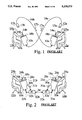
- FIG. 1 is a representation of the two person VideoDraw configuration.
- FIG. 2 is a representation of the two person Commune configuration.
- FIG. 3 is a representation of the two person video-computational shared drawing system (VideoCom).
- FIG. 4 shows the details in exploded fashion of the preferred method of preventing video feedback.
- FIG. 5 shows the VideoCom lighting installation.
- FIG. 6 is a schematic representation of using real time image canceling to control video feedback.
- FIG. 7 is a schematic representation of using colored filters to control video feedback.
- FIG. 8 illustrates various ways of sensing the position of the stylus.
- FIG. 9 shows how VideoCom work stations at remote locations can be augmented with video and audio links.
- FIG. 10 shows a three person VideoCom connection scheme using three 2-way video mixers.
- FIG. 11 shows a multi-person VideoCom connection scheme using one n-way video mixer to make the connections.
- FIG. 12 show a multi-person VideoCom connection scheme using video canceling combined with one n-way video mixer and a video bus to make the connections.
- FIG. 13 is a block diagram showing connection of multiple units using a coder/decoder unit and a communication bus.
- FIG. 14 shows several version of a large scale variation of VideoCom.
- FIG. 15 shows various ways for detecting the location of the stylus in the large scale versions of VideoCom.
- FIG. 16 shows a variation of VideoCom equipped with a recording and playback facility.
- FIG. 17 shows a variation of VideoCom equipped with a facility for looking at an auxiliary object with an auxiliary camera.
- FIG. 18 shows that VideoCom can also be equipped with an inset capability.
- FIG. 19 illustrates how VideoCom can be configured to present three-dimensional images.
- FIG. 1 shows a two person VideoDraw configuration.
- a video display unit 10 which has a display screen 18.
- a video camera 12 is mounted above each video display unit 10 and pointed at the video screen 18.
- the video camera 12a at the first workstation 11a is connected to the display unit 10b of the second workstation 11b via a video cable 16a.
- the video camera at the second workstation 11b is connected to the display unit 10a of the first workstation via another video cable 16b.
- Polarizing filters 15, not visible on FIG. 1, are mounted on each lens 13 and polarizing filters 19, not visible on FIG. 1, are mounted over each video screen 18.
- the filters 15, 19 are nearly orthogonal to each other.
- the screens 18 are uniformly illuminated by a light 23 (not illustrated), which is positioned so that it does not add glare or bothersome reflection.
- the first video camera 12a sends a signal 17a to the second video display unit 10b.
- the second video camera 12b sends a signal 17b to the first video display unit 10a.
- the lens 13a of the first video camera 12a is zoomed in on the first screen 18a.
- the lens 13b of the second video camera 12b is zoomed in on the second screen 18b.
- each collaborator or operator 25 draws on the surface of the polarizing filter 19 with dry erasable ink markers 14.
- Whiteboard markers work very well for this purpose.
- the video camera 12 transmits an image of those marks and the accompanying hand gestures to the other screen 18.
- the resulting composite image 38 can be seen be the other operator 25.
- Each collaborator 25 can add to a sketch that appears on his screen 18. At all times a complete image of the operator's hands 29, the ink marks and, possibly, the marker 14, is visible on all screens 18.
- the collaborators 25 can draw, erase, and gesture over the screens 18 much as if they were sharing a pad of paper.
- Video feedback is a phenomenon caused by positive summation, or oscillation, of a video signal through a camera that is viewing its own output in a way that nearly fills the camera's field of view.
- Video feedback being a visual phenomenon, is easier to demonstrate than describe. However, it can be thought of as the video analog of the common audio feedback or squealing which is caused by positive summation of an audio signal when the microphone is placed too near the loudspeaker in a sound amplification system.
- VideoDraw it has been found that for best operation the polarizing filters 15, 19 must be nearly orthogonal to each other. In this configuration there is actually some feedback. Allowing some feedback saturates the screen 18 and provides a white backgroung. The ambient lighting then provides a bright, uniform background to light the operator's hands 29 and the marker 14.
- FIG. 1 only shows a two person VideoDraw configuration, it would be obvious to one skilled in the art that a multi-person configuration can be constructed. It is also obvious that this apparatus can be enhanced for long distance communication by addition of audio links, that is by adding interconnected microphones and loudspeakers. Furthermore, communication among the workstations could be handled by a communication network rather than by direct cable hookup.
- FIG. 2 shows a two person Commune configuration.
- a display unit 10 which has a flat computer screen 18.
- a transparent digitizer 21 On top of the screen 18 there is a transparent digitizer 21.
- a stylus 24 is attached to the digitizer 21 via a stylus connecting cable 28.
- Signals 31, representing the position of the stylus 24 on the digitizer 21, are sent over the digitizer connection cable 30 to a personal computer central processing unit (CPU) 22.
- the CPUs 22a, 22b at each workstation 11a, 11b are interconnected via a communication cable 34.
- Display signals 32 are sent from each CPU 22 to each video display unit 10.
- the computers 22a, 22b mix the digitizer signals from each workstation 11a, 11b and present a composite image 38 of the "drawings" produced by each participant 25 with his stylus 24 on each screen 18.
- the stylus can be provided with the capability to "draw” or "erase” marks made by any or all participants 25.
- FIG. 2 only shows a two person Commune configuration, it would be obvious to one skilled in the art that a multi-person configuration can be constructed. It is also obvious that this apparatus can be enhanced for long distance communication as described above for VideoDraw.
- FIG. 3 shows the basic details of a two person video-computational shared drawing system, called VideoCom.
- VideoCom a two person video-computational shared drawing system
- this invention is a combination of VideoDraw and Commune.
- a display unit 10 which has a flat computer display screen 18, not visible on FIG. 3.
- On top of the screen 18 there is a position detector 20.
- a stylus 24 is attached to the detector 20 via a stylus connecting cable 28.
- Signals 31, representing the position of the stylus 24 on the detector 20 are sent over the detector connection cable 30 to a personal computer central processing unit (CPU) 22.
- the CPUs 22a, 22b at each workstation 11a, 11b are interconnected via a communication cable 34.
- a video camera 12 is mounted above each workstation 11 and pointed at the screen 18.
- the video camera 12a at the first workstation 11a is connected to the CPU 22b of the second workstation 11b via a video cable 16a.
- the video camera 12b at the second workstation 11b is connected to the CPU 22a of the first workstation 11a via another video cable 16b.
- the first video camera 12a sends a signal 17a to the second CPU 22b.
- the second video camera 12b sends a signal 17b to the first CPU 22a.
- Display signals 33 are sent from each CPU 22 to each display unit 10 via a connecting cable 32.
- the lens 13a of the first video camera 12a is zoomed in on first screen 18a.
- the lens 13b of the second video camera 12b is zoomed in on the second screen 18b.
- each operator 25 draws on the surface of the position detector 20 with the stylus 24. As each operator 25 draws over the screen 18, the position detector 20 transmits signals 31 to the CPU 22 to which it is attached. At the same time the video camera 12 transmits images of the accompanying hand gestures to the CPU 22 to which it is attached. In this invention the feedback prevention device 26 prevents the video camera 12 from detecting images 38 presented on the screens 18.
- the CPUs 22 at each work station 11 mix the position signals 31 and the video signals 33 and present a composite image 38 to the screen 18 at each display unit.
- Each collaborator 25 can add to a sketch that appears on the screen 18. At all times a complete image of hands 29, styli 24 and video marks is visible on all screens 18. The collaborators 25 can draw, erase, and gesture over the screens 18 much as if they were sharing a pad of paper.
- the stylus can be provided with the capability to "draw” or "erase” marks made by any or all participants 25.
- the CPU can be any personal computer, such as an IBM compatible personal computer based on a 286, 386, 486 or similar microprocessor, equipped with a video and computer overlay card, such as the New Media Graphics Video Window Card; a high resolution graphics card, such as the Video 7 VGA graphics card; and a serial communication card, such as a Digiboard.
- the video camera can be any high quality CCD camera, such as a Panasonic WDV 5000.
- the display can be a Zenith ZCM-1490 or equivalent.
- FIG. 4 shows the details in exploded fashion of the preferred method of preventing feedback at a VideoCom workstation.
- FIG. 4 shows that one polarizing filter 15 is positioned in front of the lens 13 of the video camera 12.
- Another polarizing filter 19 is positioned between the position detector 20 and the flat screen 18 of the display unit 10.
- the filters 15, 19 are orthogonal. In this configuration, no images from the screen 18 can reach the video camera 12.
- the video camera can capture images of any objects which are placed above or moved above the position detector 20. Whether the objects are in focus will depend on how close they are to the position detector 20 and the depth of focus of the lens. In most applications, the objects will be hands 29, and styli 24 moved close to the position detector 20.
- FIG. 5 shows the importance of proper lighting for proper operation of VideoCom.
- the light 23 is mounted above the display unit 10 so that it provides uniform illumination to the screen 18 while not introducing any glare or bothersome reflection. The lighting then provides a uniform ambient light to illuminate the operator's hands 29 and the stylus 24.
- FIG. 6 shows how real time image canceling could be used to control video feedback.
- the signal 17 from the camera 12 is fed to a video mixer 39, to be combined with other video signals, as well as to the CPU 22.
- the computer 22 then subtracts out the signal 17 from the mixer signal 41. This could be accomplished by analog or digital signal processing.
- the video signal 33 going to the display unit 10 is essentially devoid of video feedback.
- FIG. 7 shows how color separation can be used to control video feedback.
- the background color 44 of the screen 18 and the color 49 of objects presented on the screen 18 is selected so that a colored filter 42 placed in front of the lens 13 would block images 38, not visible on the Figure, displayed on the screen 18 in these colors 44, 49 from being detected by the camera 12.
- objects of another color 48 placed on or moved above the screen 18 are still be visible to the camera 12.
- again feedback is substantially eliminated.
- FIG. 8 illustrates various methods.
- FIG. 8A illustrates the preferred device, a transparent digitizer 21.
- the digitizer 21 has embedded detectors which enable it to continuously detect the location, projected onto the two-dimensional digitizing surface, of the stylus 24.
- the stylus 24 has a tip switch, not visible, which detects whether or not the stylus is touching the digitizer 21.
- the transparent digitizer 21 can be a Scriptel RDT-1212 or equivalent.
- FIG. 8B illustrates an alternate stylus sensing device 54. In this alternate embodiment, the flat screen is replaced with a flat active display 52.
- the stylus 24 can be cordless. This display 52 is placed over the stylus position detector 54.
- FIG. 8C shows that the camera 12 in combination with the CPU 22 can be programmed to detect the position of the stylus 24.
- the stylus 24 would preferably be pen that emits some visible signal, for example a light pen.
- FIG. 8D illustrates another device 58 which is placed on two sides of the screen 18 to detect the position of the stylus 24 in two dimensions. This device 58 can use light from an LED or sonic detection to sense the position of the stylus 24. Many devices exist, which are not illustrated, which can sense the position of the stylus 24 in two dimensions using the force applied to the stylus 24.
- FIG. 9 shows how VideoCom work stations at remote locations can be augmented with video and audio links.
- auxiliary video display 66 At each workstation 11 there is an auxiliary video display 66, an auxiliary loudspeaker 72 and an auxiliary microphone 74. These are set up and interconnect so that each operator 25 can see and talk to the other.
- FIG. 10 shows one way in which multiple workstations 11 can be interconnected. For clarity the cable connections are not numbered in this figure.
- a 2-way video mixer 39 is added to the equipment at each work station.
- the video camera 12 at one work station is connected to the mixers 39 at each of the other workstations.
- the mixers 39 mix the video signals and present them to the computers 22 for processing and presentation to the display units 10.
- the workstations 11 and the CPUs 22 are connected by a network 76.
- Three workstations 11 are shown in FIG. 10. Persons knowledgeable in the art will recognize that it is technically possible to connect many more than three workstations 11 together in this fashion.
- FIG. 11 shows another way of connecting together multiple workstations 11 into a network.
- the video cameras 12 are connected to a single n x n-way video mixer 39.
- connections are made at this one mixer 39 so that the camera 12 at one workstation 11 is connected to the CPUs 22 at each of the other workstations.
- the interconnections are shown schematically on the figure by a letter matrix applied to the representation of the mixer 39.
- the CPUs 22 are connected via a network 76, which for clarity is not shown. Again it is easy to see that, while four workstations are shown on the figure, the network can be expanded to many more workstations in this manner.
- FIG. 12 shows a third way of forming a network.
- the cameras 12 are connected to a single n-way video mixer 39.
- the output from the mixer is output to a video bus 78 to which each CPU 22 is conected.
- the video camera 12 at each workstation is also connected to the CPU 22 at each workstation.
- the video signal 17 produced at each workstation 11 is subtracted from the composite image 38 at each display unit 10 using video canceling techniques.
- the computer network 76, connecting the CPUs 22 is not shown. Again it is easy to see that, while four workstations are shown on the figure, the network can be expanded to many more workstations in this manner.
- a fourth way of forming a network is shown schematically in FIG. 13.
- all the signals, video, audio and computer are fed to a coder/decoder unit (CODEX) 84 from an audio interface 80, a video interface 82 and the CPU 22.
- CODEX 84 compresses the audio, video and computer signals presented to it at one workstation 11 and feeds them to the communication network 86. It also decompresses the combined signal 36 on the network 86 from all the other workstations 11 on the network and feeds audio, video and computer signals to its workstation 11.
- the network 86 may be a commercial communication standard network, a direct satellite link or, if 9600 baud modems are used, a telephone line.
- FIG. 14 shows several large scale versions of VideoCom.
- Large scale VideoCom the display unit 10 at each workstation 11 is replaced by a video projector 90 and a large screen 88.
- the large screen 88 is illuminated from the rear 89 by the projector 90.
- the features and operation of large scale VideoCom are otherwise the same as small scale VideoCom except that each operator 25 stands in front 87 of the screen 88 to collaborate with others on the drawing surface.
- large scale versions of VideoCom are equipped with auxiliary microphones 74 and loudspeakers 72 to facilitate communication between operators 25.
- the camera 12, can be at the rear 89 of the screen 88 as shown on FIG. 14A or at the front 87 of the screen 88 as shown on FIG. 14B.
- each collaborator 25a sees a shadow 94 of the other collaborator 25b.
- each collaborator 25 has the impression of "looking over the shoulder" of the other collaborator 25.
- FIG. 15 shows various methods for detecting the location of the stylus 24 in the large scale variations of VideoCom.
- FIG. 15A shows use of an infrared sensor 93 while
- FIG. 15B shows use of a large scale x-y sensing apparatus 93.
- the large scale sensor 92 could operate by sonic or LED detection. Other methods available but not illustrated could take advantage of image processing techniques or sensing the ultrasonic vibrations given off as the stylus 24 is moved over the screen 88.
- VideoCom Large scale versions of VideoCom can be connected into computer and video networks by the methods shown in FIGS. 10 through 13.
- FIG. 16 shows a variation of VideoCom equipped with a recording and playback facility 96. This allows the operators 25 to record and playback any prior working sessions, including their activity, recorded in video and conversations, recorded in audio.
- FIG. 17 shows a variation of VideoCom equipped with a facility for looking at an auxiliary object 98 with an auxiliary camera 70.
- the auxiliary camera 70 is multiplexed with the other video cameras 12 and connected to the CPUs 22 by means of a video switcher 39. This allows the operators 25 to view any desired object 98 at a remote locations.
- FIG. 18 shows that VideoCom can also be equipped with an inset capability using standard video inset techniques. This allows insertion of any desired inset 100 into the composite display 38.
- FIG. 19 illustrates how VideoCom can be configured to present three-dimensional images.
- a second camera 112 is placed along side the first camera 12 at each workstation 11 and connected to the CPU 22. The separation between the cameras 12 and 112 is adjusted to that required to produce stereoscopic images.
- Each operator wears a pair of shuttering spectacles 102.
- the computer derives stylus position signals from the position detectors 20 and combines them with the appropriate left and right video signals from the video cameras 12, 112. It then synchronizes the operation of the shuttering spectacles so that left and right images are presented to the operator's 25 left and right eyes in rapid succession. The operator 25 then sees three dimensional images.
- VideoCom will work with any type of video format: for example PAL or HDTV. It will also work with any type of display technology including CRTs, flat panel displays, LCD displays and plasma displays. VideoCom is a homologue of a pad of paper or a whiteboard or chalkboard. VideoCom is better than reality because multiple collaborators can interact in the same workspace at the same time.
- VideoCom Many different variations of VideoCom have been described in detail above. Although the present invention has been described in detail with reference to particular embodiments, persons possessing ordinary skill in the art to which this invention pertains will appreciate that various other modifications and enhancements may be made without departing from the spirit and scope of the claims that follow.
Abstract
Description
______________________________________ LIST OF REFERENCE NUMERALS ______________________________________ FIG. 1 10 a, bVideo display unit 11 a,b Workstation 12 a, b Video camera 14 a,b Marker 15 a, b* Camera mountedpolarizing filter 16 a, bVideo connection cable 17 a, b Video signal 18 a,b Video screen 19 a, b* Display unit mountedpolarizing filter 25 a, b Operator 23 a, b*Light 29 a, b Operator's hands 37 a, b* Video image *not visible
FIG 2 10 a,b Display unit 11 a,b Workstation 18 a, b Flatcomputer display screen 21 a, bTransparent digitizer 22 a, b Personal computer central processing unit (CPU) 24 a,b Stylus 25 a,b Operator 28 a, bStylus connection cable 29 a, b Operator'shands 30 a, b Digitizer toCPU connection cable 31 a, b Digitizer signal 32 a, b CPU to displayconnection cable 33 a,b Display signal 34 CPU toCPU communication cable 38 a, b* Composite image *not visible
FIG. 3 10 a,b Display unit 11 a,b Workstation 12 a,b Video camera 13 a,b Lens 16 a, b Camera toCPU connection cable 17 a, b Video signal 18 a, b* Flatcomputer display screen 20 a, bStylus position detector 22 a, b Personal computer central processing unit (CPU) 24 a,b Stylus 25 a, b Operator 26 a, b*Image filtering device 28 a, bStylus connection cable 29 a, b Operator'shands 30 a, b Detector toCPU connection cable 31 a, bPosition detector signal 32 a, b CPU tovideo connection cable 33 a,b Display signal 34 CPU toCPU communication cable 38 a, b Composite image *not visible
FIG. 4 10Display unit 11Workstation 12Video camera 13Lens 15 Camera mountedpolarizing filter 18Display screen 19 Display unit mountedpolarizing filter 20Stylus position detector 24Stylus 28 Stylus connection cable FIG. 5 10Display unit 11Workstation 12Video camera 13Lens 15 Camera mountedpolarizing filter 19 Display mountedpolarizing filter 21Transparent digitizer 23Light 24Stylus 29 Operator'shands 28 Stylus connection cable FIG. 6 10Display unit 12Video camera 13Lens 17Video signal 22 Personal computer central processing unit (CPU) 33Display signal 39Video mixer 41 Mixer signal FIG. 7 10Display unit 12Video camera 13Lens 18Screen 38* Composite image 42 Filter capable of blocking color A andC 44Color A background 48 Color B objects 49 Color C objects *not visible
FIG. 8
10      Display unit
12      Video camera
13      Lens
21      Transparent digitizer
22      Personal computer central processing unit (CPU)
24      Stylus
27*     Tip switch
52      Flat active display
54      Stylus x-y sensing apparatus
58      Sonic, stylus x-y sensing apparatus
FIG. 9
10 a, b Display unit
11 a, b Workstation
12 a, b Video camera
13 a, b Lens
22 a, b Personal computer central processing unit (CPU)
24 a, b Stylus
25 a, b Operator
60      Wall(s)
66 a, b Auxiliary video display
70 a, b Auxiliary video camera
71 a, b Auxiliary video signal
72 a, b Auxiliary loudspeaker
74 a, b Auxiliary microphone
75 a, b Audio signal
FIG. 10
10 a, b, c
        Display unit
11 a, b, c
        Workstation
12 a, b, c
        Video camera
13 a, b, c
        Lens
22 a, b, c
        Personal computer central processing unit (CPU)
24 a, b, c
        Stylus
39 a, b, c
        Video mixer
25 a, b, c
        Operator
76      Computer network
FIG. 11
10 a, b, c, d
        Display unit
11 a, b, c, d
        Workstation
12 a, b, c, d
        Video camera
22 a, b, c, d
        Personal computer central processing unit (CPU)
39      Video mixer
76*     Computer network
 *not shown
FIG. 12 10 a, b, c,d Display unit 12 a, b, c,d Video camera 17 a, b, c, d Video signal 22 a, b, c, d Personal computer central processing unit (CPU) 38 a, b, c,d Composite image 39Video mixer 76*Computer network 78 Video bus *not shown
FIG. 13 11 a, b,c Workstation 22 a, b, c, d Personal computer central processing unit (CPU) 36 Combinedsignal 25 a, b, c, d Operator 80 a, b, c,d Audio interface 82 a, b, c,d Video interface 84 a, b, c, d Coder/decoder 86 Communication bus FIG. 14 11 a,b Workstation 12 a,b Video camera 15 a, b Camera mountedpolarizing filter 19 a, b Screen mountedpolarizing filter 22 a, b Personal computer central processing unit (CPU) 24 a,b Stylus 25 a,b Operator 72 a,b Auxiliary loudspeaker 74 a,b Auxiliary microphone 87 a, b Front oflarge screen 88 a, bLarge screen 89 a, b Rear oflarge screen 90 a,b Video projector 92 a, b Stylus position detector 94 a, b* Operator's shadow *not visible
FIG. 15 12Video camera 24Stylus 72Auxiliary loudspeaker 88Large screen 90Video projector 92Stylus position detector 94 Shadow image of collaborator FIG. 16 10 a,b Display unit 12 a,b Video camera 22 a, b Personal computer central processing unit (CPU) 25 a,b Operator 60 Wall(s) 66 a, bAuxiliary video display 70 a, bAuxiliary video camera 96 Recording and playback facility FIG. 17 10 a,b Display unit 12 a,b Video camera 22 a, b Personal computer central processing unit (CPU) 25 a,b Operator 39Video multiplexer 60 Wall(s) 70 Auxiliary video camera 98 2 or 3-D object FIG. 18 18Screen 24Stylus 38 Composite image 99* Inset electronics 100 Inset *not visible
FIG. 19 10 a,b Display unit 11 a,b Workstation 12 a, b Video camera - used for oneimage channel 25 a,b Operator 102 a,b Shuttering spectacles 112 a, b Extra video camera - used second image channel ______________________________________
Claims (16)
Priority Applications (1)
| Application Number | Priority Date | Filing Date | Title |
|---|---|---|---|
| US07/633,900 US5239373A (en) | 1990-12-26 | 1990-12-26 | Video computational shared drawing space |
Applications Claiming Priority (1)
| Application Number | Priority Date | Filing Date | Title |
|---|---|---|---|
| US07/633,900 US5239373A (en) | 1990-12-26 | 1990-12-26 | Video computational shared drawing space |
Publications (1)
| Publication Number | Publication Date |
|---|---|
| US5239373A true US5239373A (en) | 1993-08-24 |
Family
ID=24541589
Family Applications (1)
| Application Number | Title | Priority Date | Filing Date |
|---|---|---|---|
| US07/633,900 Expired - Fee Related US5239373A (en) | 1990-12-26 | 1990-12-26 | Video computational shared drawing space |
Country Status (1)
| Country | Link |
|---|---|
| US (1) | US5239373A (en) |
Cited By (158)
| Publication number | Priority date | Publication date | Assignee | Title |
|---|---|---|---|---|
| US5400069A (en) * | 1993-06-16 | 1995-03-21 | Bell Communications Research, Inc. | Eye contact video-conferencing system and screen |
| EP0645931A1 (en) * | 1993-09-28 | 1995-03-29 | AT&T GLOBAL INFORMATION SOLUTIONS INTERNATIONAL INC. | Collaborative video conferencing system |
| US5444476A (en) * | 1992-12-11 | 1995-08-22 | The Regents Of The University Of Michigan | System and method for teleinteraction |
| US5448263A (en) * | 1991-10-21 | 1995-09-05 | Smart Technologies Inc. | Interactive display system |
| EP0673162A2 (en) * | 1994-03-15 | 1995-09-20 | Alcatel SEL Aktiengesellschaft | Communication system |
| WO1995030301A1 (en) * | 1994-04-29 | 1995-11-09 | Siemens Aktiengesellschaft | Telecommunications system for transmitting images |
| WO1995034051A1 (en) * | 1994-06-06 | 1995-12-14 | Spectragraphics Corporation | Method and apparatus for capturing and distributing graphical data |
| US5502514A (en) * | 1995-06-07 | 1996-03-26 | Nview Corporation | Stylus position sensing and digital camera with a digital micromirror device |
| US5511148A (en) * | 1993-04-30 | 1996-04-23 | Xerox Corporation | Interactive copying system |
| US5517210A (en) * | 1993-02-26 | 1996-05-14 | Hitachi, Ltd. | Multi-scan type display system with pointer function |
| US5528263A (en) * | 1994-06-15 | 1996-06-18 | Daniel M. Platzker | Interactive projected video image display system |
| US5530797A (en) * | 1992-04-09 | 1996-06-25 | Matsushita Electric Industrial Co., Ltd. | Workstation for simultaneously displaying overlapped windows using a priority control register |
| US5579481A (en) * | 1992-07-31 | 1996-11-26 | International Business Machines Corporation | System and method for controlling data transfer between multiple interconnected computer systems with an untethered stylus |
| US5587559A (en) * | 1994-11-18 | 1996-12-24 | Wacom Co., Ltd. | Control method of a plurality of locators and control device of same |
| US5608872A (en) * | 1993-03-19 | 1997-03-04 | Ncr Corporation | System for allowing all remote computers to perform annotation on an image and replicating the annotated image on the respective displays of other comuters |
| US5612736A (en) * | 1995-06-07 | 1997-03-18 | Nview Corporation | Stylus position sensing and digital camera with a digital micromirror device |
| US5619253A (en) * | 1993-06-25 | 1997-04-08 | Miranda, Jr.; Henry A. | Video display of indicia |
| US5623559A (en) * | 1992-01-24 | 1997-04-22 | Ricoh Company, Ltd. | Communication terminal transmitting first and second coordinate data in first and second modes |
| US5633691A (en) * | 1995-06-07 | 1997-05-27 | Nview Corporation | Stylus position sensing and digital camera with a digital micromirror device |
| US5677728A (en) * | 1982-02-24 | 1997-10-14 | Schoolman Scientific Corporation | Stereoscopic video telecommunication system |
| US5737740A (en) * | 1994-06-27 | 1998-04-07 | Numonics | Apparatus and method for processing electronic documents |
| US5736687A (en) * | 1996-08-21 | 1998-04-07 | Compaq Computer Corporation | Digitizer utilizing heat source detection to receive input information |
| US5742279A (en) * | 1993-11-08 | 1998-04-21 | Matsushita Electrical Co., Ltd. | Input/display integrated information processing device |
| US5751959A (en) * | 1995-04-20 | 1998-05-12 | Canon Kabushiki Kaisha | Communication terminal, supervisory system and communication method |
| US5767842A (en) * | 1992-02-07 | 1998-06-16 | International Business Machines Corporation | Method and device for optical input of commands or data |
| US5781174A (en) * | 1992-07-14 | 1998-07-14 | Matsushita Electric Industrial Co., Ltd. | Image synthesizer and image pointing system |
| US5802516A (en) * | 1993-11-03 | 1998-09-01 | Apple Computer, Inc. | Method of controlling an electronic book for a computer system |
| WO1998047406A2 (en) * | 1997-04-23 | 1998-10-29 | Technion Research And Development Foundation | Interactive desk |
| US5831601A (en) * | 1995-06-07 | 1998-11-03 | Nview Corporation | Stylus position sensing and digital camera with a digital micromirror device |
| US5832065A (en) * | 1994-06-07 | 1998-11-03 | Northern Telecom Limited | Synchronous voice/data message system |
| US5874951A (en) * | 1994-02-28 | 1999-02-23 | Fuji Xerox Co., Ltd. | Drawing communication apparatus using time stamps that indicate an order of occurrence of operation events |
| US5897648A (en) * | 1994-06-27 | 1999-04-27 | Numonics Corporation | Apparatus and method for editing electronic documents |
| EP0924929A2 (en) * | 1997-12-22 | 1999-06-23 | Nortel Networks Corporation | Video conferencing system |
| US5969754A (en) * | 1996-12-09 | 1999-10-19 | Zeman; Herbert D. | Contrast enhancing illuminator |
| US5973676A (en) * | 1993-06-30 | 1999-10-26 | Kabushiki Kaisha Toshiba | Input apparatus suitable for portable electronic device |
| WO1999061975A2 (en) * | 1998-05-27 | 1999-12-02 | Koninklijke Philips Electronics N.V. | A system for image generation with screen means and means for image-wise mixing with a received user image |
| WO2000002187A1 (en) * | 1998-07-01 | 2000-01-13 | Deluca Michael J | Stereoscopic user interface method and apparatus |
| US6061177A (en) * | 1996-12-19 | 2000-05-09 | Fujimoto; Kenneth Noboru | Integrated computer display and graphical input apparatus and method |
| US6094189A (en) * | 1998-04-17 | 2000-07-25 | Quillen; Wendell A. | Visual echo remote laser pointer |
| US6141000A (en) * | 1991-10-21 | 2000-10-31 | Smart Technologies Inc. | Projection display system with touch sensing on screen, computer assisted alignment correction and network conferencing |
| EP1057169A1 (en) * | 1998-10-02 | 2000-12-06 | Tegrity Incorpororated | Method and apparatus for processing, displaying and communicating images |
| US6209021B1 (en) * | 1993-04-13 | 2001-03-27 | Intel Corporation | System for computer supported collaboration |
| WO2001052230A1 (en) * | 2000-01-10 | 2001-07-19 | Ic Tech, Inc. | Method and system for interacting with a display |
| US6288753B1 (en) | 1999-07-07 | 2001-09-11 | Corrugated Services Corp. | System and method for live interactive distance learning |
| US20020002490A1 (en) * | 2000-03-29 | 2002-01-03 | George Gerpheide | Personalized computer peripheral |
| WO2002043390A2 (en) * | 2000-11-06 | 2002-05-30 | Jianbo Shi | Paper-based remote sketching system |
| US6417969B1 (en) | 1988-07-01 | 2002-07-09 | Deluca Michael | Multiple viewer headset display apparatus and method with second person icon display |
| US20020093666A1 (en) * | 2001-01-17 | 2002-07-18 | Jonathan Foote | System and method for determining the location of a target in a room or small area |
| US20020124479A1 (en) * | 1997-03-13 | 2002-09-12 | Branc Joseph R. | Workspace display |
| US20020186221A1 (en) * | 2001-06-05 | 2002-12-12 | Reactrix Systems, Inc. | Interactive video display system |
| US20030076293A1 (en) * | 2000-03-13 | 2003-04-24 | Hans Mattsson | Gesture recognition system |
| US20030081014A1 (en) * | 2001-10-31 | 2003-05-01 | Frohlich David Mark | Method and apparatus for assisting the reading of a document |
| US6563520B1 (en) | 1996-05-01 | 2003-05-13 | Light And Sound Design Ltd. | Virtual reality interface for show control |
| US6611822B1 (en) * | 1999-05-05 | 2003-08-26 | Ac Properties B.V. | System method and article of manufacture for creating collaborative application sharing |
| US20030179313A1 (en) * | 2002-03-19 | 2003-09-25 | Mormino Thomas Anthony | Desktop video teleconferencing device combining an erasable writing-board & camera |
| US6707434B1 (en) * | 1992-10-03 | 2004-03-16 | International Business Machines Corporation | Computer workstation |
| US20040070552A1 (en) * | 2002-08-06 | 2004-04-15 | Fuji Photo Optical Co., Ltd. | Material presentation device |
| US20040070674A1 (en) * | 2002-10-15 | 2004-04-15 | Foote Jonathan T. | Method, apparatus, and system for remotely annotating a target |
| US20040070616A1 (en) * | 2002-06-02 | 2004-04-15 | Hildebrandt Peter W. | Electronic whiteboard |
| US20040075820A1 (en) * | 2002-10-22 | 2004-04-22 | Chu Simon C. | System and method for presenting, capturing, and modifying images on a presentation board |
| WO2004055776A1 (en) * | 2002-12-13 | 2004-07-01 | Reactrix Systems | Interactive directed light/sound system |
| US20040174698A1 (en) * | 2002-05-08 | 2004-09-09 | Fuji Photo Optical Co., Ltd. | Light pen and presentation system having the same |
| US20040183775A1 (en) * | 2002-12-13 | 2004-09-23 | Reactrix Systems | Interactive directed light/sound system |
| US20040201698A1 (en) * | 2001-06-08 | 2004-10-14 | Keenan Vaughn E. | Camera-based system for capturing images of a target area |
| US20050078092A1 (en) * | 2003-10-08 | 2005-04-14 | Clapper Edward O. | Whiteboard desk projection display |
| US6882358B1 (en) * | 2002-10-02 | 2005-04-19 | Terabeam Corporation | Apparatus, system and method for enabling eye-to-eye contact in video conferences |
| US20050110964A1 (en) * | 2002-05-28 | 2005-05-26 | Matthew Bell | Interactive video window display system |
| US20050166163A1 (en) * | 2004-01-23 | 2005-07-28 | Chang Nelson L.A. | Systems and methods of interfacing with a machine |
| WO2005103744A2 (en) * | 2004-04-23 | 2005-11-03 | Siemens Aktiengesellschaft | Arrangement and method for carrying out video conferences |
| US20050270367A1 (en) * | 1996-11-13 | 2005-12-08 | Fakespace Labs, Inc. | Multi-person stereo display system |
| US20060031786A1 (en) * | 2004-08-06 | 2006-02-09 | Hillis W D | Method and apparatus continuing action of user gestures performed upon a touch sensitive interactive display in simulation of inertia |
| US20060117669A1 (en) * | 2004-12-06 | 2006-06-08 | Baloga Mark A | Multi-use conferencing space, table arrangement and display configuration |
| US20060125799A1 (en) * | 2004-08-06 | 2006-06-15 | Hillis W D | Touch driven method and apparatus to integrate and display multiple image layers forming alternate depictions of same subject matter |
| WO2007003712A1 (en) * | 2005-06-30 | 2007-01-11 | Nokia Corporation | Control device for information display, corresponding system, method and program product |
| US20070046643A1 (en) * | 2004-08-06 | 2007-03-01 | Hillis W Daniel | State-Based Approach to Gesture Identification |
| US20080013826A1 (en) * | 2006-07-13 | 2008-01-17 | Northrop Grumman Corporation | Gesture recognition interface system |
| US20080018740A1 (en) * | 2006-07-18 | 2008-01-24 | Fuji Xerox Co., Ltd. | Remote instruction system |
| US20080028325A1 (en) * | 2006-07-25 | 2008-01-31 | Northrop Grumman Corporation | Networked gesture collaboration system |
| US20080043106A1 (en) * | 2006-08-10 | 2008-02-21 | Northrop Grumman Corporation | Stereo camera intrusion detection system |
| US7427983B1 (en) * | 2002-06-02 | 2008-09-23 | Steelcase Development Corporation | Visual communication system |
| US20080244468A1 (en) * | 2006-07-13 | 2008-10-02 | Nishihara H Keith | Gesture Recognition Interface System with Vertical Display |
| US20080259184A1 (en) * | 2007-04-19 | 2008-10-23 | Fuji Xerox Co., Ltd. | Information processing device and computer readable recording medium |
| US20080316348A1 (en) * | 2007-06-21 | 2008-12-25 | Cisco Technology, Inc. | Virtual whiteboard |
| US20090103780A1 (en) * | 2006-07-13 | 2009-04-23 | Nishihara H Keith | Hand-Gesture Recognition Method |
| US20090116742A1 (en) * | 2007-11-01 | 2009-05-07 | H Keith Nishihara | Calibration of a Gesture Recognition Interface System |
| US20090115721A1 (en) * | 2007-11-02 | 2009-05-07 | Aull Kenneth W | Gesture Recognition Light and Video Image Projector |
| WO2009058641A1 (en) | 2007-11-01 | 2009-05-07 | Cisco Technology, Inc. | Virtual table |
| US7619617B2 (en) | 2002-11-15 | 2009-11-17 | Smart Technologies Ulc | Size/scale and orientation determination of a pointer in a camera-based touch system |
| US20090316952A1 (en) * | 2008-06-20 | 2009-12-24 | Bran Ferren | Gesture recognition interface system with a light-diffusive screen |
| US7643006B2 (en) | 2003-09-16 | 2010-01-05 | Smart Technologies Ulc | Gesture recognition method and touch system incorporating the same |
| US20100050133A1 (en) * | 2008-08-22 | 2010-02-25 | Nishihara H Keith | Compound Gesture Recognition |
| US20100103243A1 (en) * | 2008-10-27 | 2010-04-29 | Jong Pil Won | Method and apparatus for transmitting and receiving data using mobile terminal |
| US20100117979A1 (en) * | 2004-08-06 | 2010-05-13 | Touchtable, Inc. | Bounding box gesture recognition on a touch detecting interactive display |
| US20100130364A1 (en) * | 2007-06-19 | 2010-05-27 | Casana Giner Victor | Oil suspensions of sulphonylureas and agrochemical combinations |
| US20100214469A1 (en) * | 2009-02-26 | 2010-08-26 | Keith Brent Duncan | System, components, and methods for viewing documents and objects using a webcam |
| US7809167B2 (en) | 2003-10-24 | 2010-10-05 | Matthew Bell | Method and system for processing captured image information in an interactive video display system |
| US20100302454A1 (en) * | 2007-10-12 | 2010-12-02 | Lewis Epstein | Personal Control Apparatus And Method For Sharing Information In A Collaborative Workspace |
| US20100321561A1 (en) * | 2009-02-26 | 2010-12-23 | Keith Brent Duncan | System, components, and methods for viewing documents and objects using a webcam |
| US20110096091A1 (en) * | 2008-06-24 | 2011-04-28 | Monmouth University | System and method for viewing and marking maps |
| US20110100730A1 (en) * | 2009-11-04 | 2011-05-05 | Hon Hai Precision Industry Co., Ltd. | Handwriting input system |
| US20110169778A1 (en) * | 2010-01-08 | 2011-07-14 | Crayola Llc | Interactive projection system |
| US20110197263A1 (en) * | 2010-02-11 | 2011-08-11 | Verizon Patent And Licensing, Inc. | Systems and methods for providing a spatial-input-based multi-user shared display experience |
| USRE42794E1 (en) | 1999-12-27 | 2011-10-04 | Smart Technologies Ulc | Information-inputting device inputting contact point of object on recording surfaces as information |
| US8035624B2 (en) | 2002-05-28 | 2011-10-11 | Intellectual Ventures Holding 67 Llc | Computer vision based touch screen |
| US8055022B2 (en) | 2000-07-05 | 2011-11-08 | Smart Technologies Ulc | Passive touch system and method of detecting user input |
| US8081822B1 (en) | 2005-05-31 | 2011-12-20 | Intellectual Ventures Holding 67 Llc | System and method for sensing a feature of an object in an interactive video display |
| US8089462B2 (en) | 2004-01-02 | 2012-01-03 | Smart Technologies Ulc | Pointer tracking across multiple overlapping coordinate input sub-regions defining a generally contiguous input region |
| USRE43084E1 (en) | 1999-10-29 | 2012-01-10 | Smart Technologies Ulc | Method and apparatus for inputting information including coordinate data |
| US8094137B2 (en) | 2007-07-23 | 2012-01-10 | Smart Technologies Ulc | System and method of detecting contact on a display |
| US8098277B1 (en) | 2005-12-02 | 2012-01-17 | Intellectual Ventures Holding 67 Llc | Systems and methods for communication between a reactive video system and a mobile communication device |
| US20120026275A1 (en) * | 2009-04-16 | 2012-02-02 | Robinson Ian N | Communicating visual representations in virtual collaboration systems |
| US8115753B2 (en) | 2007-04-11 | 2012-02-14 | Next Holdings Limited | Touch screen system with hover and click input methods |
| US8120596B2 (en) | 2004-05-21 | 2012-02-21 | Smart Technologies Ulc | Tiled touch system |
| US8149221B2 (en) | 2004-05-07 | 2012-04-03 | Next Holdings Limited | Touch panel display system with illumination and detection provided from a single edge |
| US8159682B2 (en) | 2007-11-12 | 2012-04-17 | Intellectual Ventures Holding 67 Llc | Lens system |
| US8230367B2 (en) | 2007-09-14 | 2012-07-24 | Intellectual Ventures Holding 67 Llc | Gesture-based user interactions with status indicators for acceptable inputs in volumetric zones |
| US8259163B2 (en) | 2008-03-07 | 2012-09-04 | Intellectual Ventures Holding 67 Llc | Display with built in 3D sensing |
| US20120223960A1 (en) * | 2011-03-01 | 2012-09-06 | Avermedia Information, Inc. | Image control method and image control system |
| US8274496B2 (en) | 2004-04-29 | 2012-09-25 | Smart Technologies Ulc | Dual mode touch systems |
| US8289299B2 (en) | 2003-02-14 | 2012-10-16 | Next Holdings Limited | Touch screen signal processing |
| US8300042B2 (en) | 2001-06-05 | 2012-10-30 | Microsoft Corporation | Interactive video display system using strobed light |
| US8339378B2 (en) | 2008-11-05 | 2012-12-25 | Smart Technologies Ulc | Interactive input system with multi-angle reflector |
| US8384693B2 (en) | 2007-08-30 | 2013-02-26 | Next Holdings Limited | Low profile touch panel systems |
| US20130063547A1 (en) * | 2010-05-17 | 2013-03-14 | Yuuji Kasuya | Multiple-site drawn-image sharing apparatus, multiple-site drawn-image sharing system, method executed by multiple-site drawn-image sharing apparatus, program, and recording medium |
| US8405637B2 (en) | 2008-01-07 | 2013-03-26 | Next Holdings Limited | Optical position sensing system and optical position sensor assembly with convex imaging window |
| US8432377B2 (en) | 2007-08-30 | 2013-04-30 | Next Holdings Limited | Optical touchscreen with improved illumination |
| US8456447B2 (en) | 2003-02-14 | 2013-06-04 | Next Holdings Limited | Touch screen signal processing |
| US8456418B2 (en) | 2003-10-09 | 2013-06-04 | Smart Technologies Ulc | Apparatus for determining the location of a pointer within a region of interest |
| US8456451B2 (en) | 2003-03-11 | 2013-06-04 | Smart Technologies Ulc | System and method for differentiating between pointers used to contact touch surface |
| US8487866B2 (en) | 2003-10-24 | 2013-07-16 | Intellectual Ventures Holding 67 Llc | Method and system for managing an interactive video display system |
| US8508508B2 (en) | 2003-02-14 | 2013-08-13 | Next Holdings Limited | Touch screen signal processing with single-point calibration |
| US8593402B2 (en) | 2010-04-30 | 2013-11-26 | Verizon Patent And Licensing Inc. | Spatial-input-based cursor projection systems and methods |
| US8595218B2 (en) | 2008-06-12 | 2013-11-26 | Intellectual Ventures Holding 67 Llc | Interactive display management systems and methods |
| US8692768B2 (en) | 2009-07-10 | 2014-04-08 | Smart Technologies Ulc | Interactive input system |
| US8902193B2 (en) | 2008-05-09 | 2014-12-02 | Smart Technologies Ulc | Interactive input system and bezel therefor |
| EP1564682A3 (en) * | 2004-02-17 | 2014-12-03 | Microsoft Corporation | A system and method for visual echo cancellation in a projector-camera-whiteboard system |
| US8957856B2 (en) | 2010-10-21 | 2015-02-17 | Verizon Patent And Licensing Inc. | Systems, methods, and apparatuses for spatial input associated with a display |
| US9128519B1 (en) | 2005-04-15 | 2015-09-08 | Intellectual Ventures Holding 67 Llc | Method and system for state-based control of objects |
| US9164975B2 (en) | 2008-06-24 | 2015-10-20 | Monmouth University | System and method for viewing and marking maps |
| US9167289B2 (en) | 2010-09-02 | 2015-10-20 | Verizon Patent And Licensing Inc. | Perspective display systems and methods |
| WO2016131507A1 (en) | 2015-02-18 | 2016-08-25 | Gök Metin | Method and system for exchanging information |
| US9442607B2 (en) | 2006-12-04 | 2016-09-13 | Smart Technologies Inc. | Interactive input system and method |
| US9465524B2 (en) | 2008-10-13 | 2016-10-11 | Steelcase Inc. | Control apparatus and method for sharing information in a collaborative workspace |
| JP2017175580A (en) * | 2016-03-25 | 2017-09-28 | パナソニックIpマネジメント株式会社 | Information display system and information providing terminal |
| US20170361209A1 (en) * | 2014-12-04 | 2017-12-21 | Dov Rotshtain | Computer-controlled board games |
| US20180152668A1 (en) * | 2015-06-25 | 2018-05-31 | Panasonic Intellectual Property Management Co., Ltd. | Information display system and information display terminal |
| US20190075272A1 (en) * | 2016-03-25 | 2019-03-07 | Panasonic Intellectual Property Management Co., Ltd. | Information displaying system and information providing terminal |
| US10264213B1 (en) | 2016-12-15 | 2019-04-16 | Steelcase Inc. | Content amplification system and method |
| US10338793B2 (en) | 2014-04-25 | 2019-07-02 | Timothy Isaac FISHER | Messaging with drawn graphic input |
| US10492608B2 (en) | 2004-12-06 | 2019-12-03 | Steelcase Inc. | Multi-use conferencing space, table arrangement and display configuration |
| US10515561B1 (en) * | 2013-03-15 | 2019-12-24 | Study Social, Inc. | Video presentation, digital compositing, and streaming techniques implemented via a computer network |
| US10631632B2 (en) | 2008-10-13 | 2020-04-28 | Steelcase Inc. | Egalitarian control apparatus and method for sharing information in a collaborative workspace |
| US10884607B1 (en) | 2009-05-29 | 2021-01-05 | Steelcase Inc. | Personal control apparatus and method for sharing information in a collaborative workspace |
| US11095850B2 (en) * | 2018-02-26 | 2021-08-17 | Panasonic Intellectual Property Management Co., Ltd. | Bidirectional video communication system and communication control device |
| US20220368853A1 (en) * | 2021-05-13 | 2022-11-17 | Graham Smith | Multimodal Video Conferencing Device |
| US20230120371A1 (en) * | 2021-10-15 | 2023-04-20 | Motorola Mobility Llc | Composite presentation surface and presenter imaging for a multiple camera transmitting device in a video communication session |
| US20230118446A1 (en) * | 2021-10-15 | 2023-04-20 | Motorola Mobility Llc | Dynamic presentation surface and presenter imaging for a receiving device in a video communication session |
| WO2024019713A1 (en) * | 2022-07-20 | 2024-01-25 | Google Llc | Copresence system |
Citations (11)
| Publication number | Priority date | Publication date | Assignee | Title |
|---|---|---|---|---|
| US3584162A (en) * | 1970-02-16 | 1971-06-08 | Ibm | Electrical keyboard switch mechanism with improved resilient diaphragm contact actuator |
| US3618035A (en) * | 1969-04-17 | 1971-11-02 | Bell Telephone Labor Inc | Video-telephone computer graphics system |
| US3755623A (en) * | 1970-10-22 | 1973-08-28 | Matra Engins | Combined television camera and a television receiver unit |
| DE2433667A1 (en) * | 1974-07-12 | 1976-01-22 | Standard Elektrik Lorenz Ag | Communications system for transmitting and displaying characters - allows telephone conversation to be illustrated at all receivers by sketches etc. |
| DE2628709A1 (en) * | 1976-06-25 | 1977-12-29 | Siemens Ag | TV and telephone link for documents - permits transmission of images and marking joints by light pen with compensation for transit time delay |
| US4371893A (en) * | 1979-09-11 | 1983-02-01 | Rabeisen Andre J | Video communication system allowing graphic additions to the images communicated |
| US4400724A (en) * | 1981-06-08 | 1983-08-23 | The United States Of America As Represented By The Secretary Of The Army | Virtual space teleconference system |
| US4430526A (en) * | 1982-01-25 | 1984-02-07 | Bell Telephone Laboratories, Incorporated | Interactive graphics transmission system employing an adaptive stylus for reduced bandwidth |
| US4561017A (en) * | 1983-08-19 | 1985-12-24 | Richard Greene | Graphic input apparatus |
| US4821118A (en) * | 1986-10-09 | 1989-04-11 | Advanced Identification Systems, Inc. | Video image system for personal identification |
| US5073926A (en) * | 1989-01-20 | 1991-12-17 | Asch Corporation | Picture communication apparatus |
-
1990
- 1990-12-26 US US07/633,900 patent/US5239373A/en not_active Expired - Fee Related
Patent Citations (11)
| Publication number | Priority date | Publication date | Assignee | Title |
|---|---|---|---|---|
| US3618035A (en) * | 1969-04-17 | 1971-11-02 | Bell Telephone Labor Inc | Video-telephone computer graphics system |
| US3584162A (en) * | 1970-02-16 | 1971-06-08 | Ibm | Electrical keyboard switch mechanism with improved resilient diaphragm contact actuator |
| US3755623A (en) * | 1970-10-22 | 1973-08-28 | Matra Engins | Combined television camera and a television receiver unit |
| DE2433667A1 (en) * | 1974-07-12 | 1976-01-22 | Standard Elektrik Lorenz Ag | Communications system for transmitting and displaying characters - allows telephone conversation to be illustrated at all receivers by sketches etc. |
| DE2628709A1 (en) * | 1976-06-25 | 1977-12-29 | Siemens Ag | TV and telephone link for documents - permits transmission of images and marking joints by light pen with compensation for transit time delay |
| US4371893A (en) * | 1979-09-11 | 1983-02-01 | Rabeisen Andre J | Video communication system allowing graphic additions to the images communicated |
| US4400724A (en) * | 1981-06-08 | 1983-08-23 | The United States Of America As Represented By The Secretary Of The Army | Virtual space teleconference system |
| US4430526A (en) * | 1982-01-25 | 1984-02-07 | Bell Telephone Laboratories, Incorporated | Interactive graphics transmission system employing an adaptive stylus for reduced bandwidth |
| US4561017A (en) * | 1983-08-19 | 1985-12-24 | Richard Greene | Graphic input apparatus |
| US4821118A (en) * | 1986-10-09 | 1989-04-11 | Advanced Identification Systems, Inc. | Video image system for personal identification |
| US5073926A (en) * | 1989-01-20 | 1991-12-17 | Asch Corporation | Picture communication apparatus |
Non-Patent Citations (15)
| Title |
|---|
| "Dram & Personality in User Interface Design (Panel)", May 1989, CHI '89 Proceedings. |
| Dram & Personality in User Interface Design (Panel) , May 1989, CHI 89 Proceedings. * |
| Hiroshi Ishii, "TeamWorkStation: Towards a Seamless Shared Workspace", Oct. 1990, CSCW '90. |
| Hiroshi Ishii, TeamWorkStation: Towards a Seamless Shared Workspace , Oct. 1990, CSCW 90. * |
| Jack F. Gerrissen et al., "Inclusion of a `Sharing` Feature in Telecommunication Services", Sep. 1990, HFT '90. |
| Jack F. Gerrissen et al., Inclusion of a Sharing Feature in Telecommunication Services , Sep. 1990, HFT 90. * |
| Jakob Nielsen, "CHI '89 Trip Report", Oct. 1989, SIGCHI Bulletin, Vol. 21, No. 2. |
| Jakob Nielsen, CHI 89 Trip Report , Oct. 1989, SIGCHI Bulletin, Vol. 21, No. 2. * |
| John C. Tang, Listing, Drawing & Gesturing in Design: A Study of the Use of Shared Workspace by Design Teams, Apr. 1989. * |
| Krueger, Myron A., "Artificial Reality", 1982, pp. 124-128. |
| Krueger, Myron A., Artificial Reality , 1982, pp. 124 128. * |
| Michon; Brian, "Integrating Motion Video into Computational Environments", Oct. 1989, SIGCHI Bulletin, pp. 80-82. |
| Michon; Brian, Integrating Motion Video into Computational Environments , Oct. 1989, SIGCHI Bulletin, pp. 80 82. * |
| Paul Milgram et al., "A Virtual Stereographic Pointer for a Real Three Dimensional Video World", INTERACT '90, Aug. 1990. |
| Paul Milgram et al., A Virtual Stereographic Pointer for a Real Three Dimensional Video World , INTERACT 90, Aug. 1990. * |
Cited By (297)
| Publication number | Priority date | Publication date | Assignee | Title |
|---|---|---|---|---|
| US5677728A (en) * | 1982-02-24 | 1997-10-14 | Schoolman Scientific Corporation | Stereoscopic video telecommunication system |
| US6417969B1 (en) | 1988-07-01 | 2002-07-09 | Deluca Michael | Multiple viewer headset display apparatus and method with second person icon display |
| US7289113B2 (en) | 1991-10-21 | 2007-10-30 | Smart Technologies Inc. | Projection display system with pressure sensing at screen, and computer assisted alignment implemented by applying pressure at displayed calibration marks |
| US5448263A (en) * | 1991-10-21 | 1995-09-05 | Smart Technologies Inc. | Interactive display system |
| US7626577B2 (en) | 1991-10-21 | 2009-12-01 | Smart Technologies Ulc | Projection display system with pressure sensing at a screen, a calibration system corrects for non-orthogonal projection errors |
| US20080042999A1 (en) * | 1991-10-21 | 2008-02-21 | Martin David A | Projection display system with pressure sensing at a screen, a calibration system corrects for non-orthogonal projection errors |
| US6747636B2 (en) | 1991-10-21 | 2004-06-08 | Smart Technologies, Inc. | Projection display and system with pressure sensing at screen, and computer assisted alignment implemented by applying pressure at displayed calibration marks |
| US20040263488A1 (en) * | 1991-10-21 | 2004-12-30 | Martin David A | Projection display system with pressure sensing at screen, and computer assisted alignment implemented by applying pressure at displayed calibration marks |
| US6337681B1 (en) | 1991-10-21 | 2002-01-08 | Smart Technologies Inc. | Projection display system with pressure sensing at screen, and computer assisted alignment implemented by applying pressure at displayed calibration marks |
| US6141000A (en) * | 1991-10-21 | 2000-10-31 | Smart Technologies Inc. | Projection display system with touch sensing on screen, computer assisted alignment correction and network conferencing |
| US5623559A (en) * | 1992-01-24 | 1997-04-22 | Ricoh Company, Ltd. | Communication terminal transmitting first and second coordinate data in first and second modes |
| US5767842A (en) * | 1992-02-07 | 1998-06-16 | International Business Machines Corporation | Method and device for optical input of commands or data |
| US5530797A (en) * | 1992-04-09 | 1996-06-25 | Matsushita Electric Industrial Co., Ltd. | Workstation for simultaneously displaying overlapped windows using a priority control register |
| US5781174A (en) * | 1992-07-14 | 1998-07-14 | Matsushita Electric Industrial Co., Ltd. | Image synthesizer and image pointing system |
| US5579481A (en) * | 1992-07-31 | 1996-11-26 | International Business Machines Corporation | System and method for controlling data transfer between multiple interconnected computer systems with an untethered stylus |
| US6707434B1 (en) * | 1992-10-03 | 2004-03-16 | International Business Machines Corporation | Computer workstation |
| US5444476A (en) * | 1992-12-11 | 1995-08-22 | The Regents Of The University Of Michigan | System and method for teleinteraction |
| US5517210A (en) * | 1993-02-26 | 1996-05-14 | Hitachi, Ltd. | Multi-scan type display system with pointer function |
| US5608872A (en) * | 1993-03-19 | 1997-03-04 | Ncr Corporation | System for allowing all remote computers to perform annotation on an image and replicating the annotated image on the respective displays of other comuters |
| US5872923A (en) * | 1993-03-19 | 1999-02-16 | Ncr Corporation | Collaborative video conferencing system |
| US6209021B1 (en) * | 1993-04-13 | 2001-03-27 | Intel Corporation | System for computer supported collaboration |
| US5511148A (en) * | 1993-04-30 | 1996-04-23 | Xerox Corporation | Interactive copying system |
| US5400069A (en) * | 1993-06-16 | 1995-03-21 | Bell Communications Research, Inc. | Eye contact video-conferencing system and screen |
| US5619253A (en) * | 1993-06-25 | 1997-04-08 | Miranda, Jr.; Henry A. | Video display of indicia |
| US5973676A (en) * | 1993-06-30 | 1999-10-26 | Kabushiki Kaisha Toshiba | Input apparatus suitable for portable electronic device |
| EP0645931A1 (en) * | 1993-09-28 | 1995-03-29 | AT&T GLOBAL INFORMATION SOLUTIONS INTERNATIONAL INC. | Collaborative video conferencing system |
| US5802516A (en) * | 1993-11-03 | 1998-09-01 | Apple Computer, Inc. | Method of controlling an electronic book for a computer system |
| US6040825A (en) * | 1993-11-08 | 2000-03-21 | Matsushita Electric Industrial Co., Ltd. | Input/display integrated information processing device |
| US5742279A (en) * | 1993-11-08 | 1998-04-21 | Matsushita Electrical Co., Ltd. | Input/display integrated information processing device |
| US5874951A (en) * | 1994-02-28 | 1999-02-23 | Fuji Xerox Co., Ltd. | Drawing communication apparatus using time stamps that indicate an order of occurrence of operation events |
| EP0673162A3 (en) * | 1994-03-15 | 1996-04-24 | Sel Alcatel Ag | Communication system. |
| EP0673162A2 (en) * | 1994-03-15 | 1995-09-20 | Alcatel SEL Aktiengesellschaft | Communication system |
| US6285471B1 (en) | 1994-04-29 | 2001-09-04 | Siemens Aktiengesellschaft | Telecommunications system for transmitting images |
| WO1995030301A1 (en) * | 1994-04-29 | 1995-11-09 | Siemens Aktiengesellschaft | Telecommunications system for transmitting images |
| US20010035979A1 (en) * | 1994-04-29 | 2001-11-01 | Fritz Pornbacher | Telecommunications system for transmitting images |
| WO1995034051A1 (en) * | 1994-06-06 | 1995-12-14 | Spectragraphics Corporation | Method and apparatus for capturing and distributing graphical data |
| US5832065A (en) * | 1994-06-07 | 1998-11-03 | Northern Telecom Limited | Synchronous voice/data message system |
| US5528263A (en) * | 1994-06-15 | 1996-06-18 | Daniel M. Platzker | Interactive projected video image display system |
| US5897648A (en) * | 1994-06-27 | 1999-04-27 | Numonics Corporation | Apparatus and method for editing electronic documents |
| US5737740A (en) * | 1994-06-27 | 1998-04-07 | Numonics | Apparatus and method for processing electronic documents |
| US5587559A (en) * | 1994-11-18 | 1996-12-24 | Wacom Co., Ltd. | Control method of a plurality of locators and control device of same |
| US5751959A (en) * | 1995-04-20 | 1998-05-12 | Canon Kabushiki Kaisha | Communication terminal, supervisory system and communication method |
| US5502514A (en) * | 1995-06-07 | 1996-03-26 | Nview Corporation | Stylus position sensing and digital camera with a digital micromirror device |
| US5612736A (en) * | 1995-06-07 | 1997-03-18 | Nview Corporation | Stylus position sensing and digital camera with a digital micromirror device |
| US5633691A (en) * | 1995-06-07 | 1997-05-27 | Nview Corporation | Stylus position sensing and digital camera with a digital micromirror device |
| US5831601A (en) * | 1995-06-07 | 1998-11-03 | Nview Corporation | Stylus position sensing and digital camera with a digital micromirror device |
| US6563520B1 (en) | 1996-05-01 | 2003-05-13 | Light And Sound Design Ltd. | Virtual reality interface for show control |
| US7761803B2 (en) | 1996-05-01 | 2010-07-20 | Production Resource Group, Inc. | Virtual reality interface for show control |
| US20100287487A1 (en) * | 1996-05-01 | 2010-11-11 | Production Resource Group, L.L.C. | Virtual Reality Interface for Show Control |
| US5736687A (en) * | 1996-08-21 | 1998-04-07 | Compaq Computer Corporation | Digitizer utilizing heat source detection to receive input information |
| US8223197B2 (en) * | 1996-11-13 | 2012-07-17 | Fakespace Labs, Inc. | Multi-person stereo display system |
| US20050270367A1 (en) * | 1996-11-13 | 2005-12-08 | Fakespace Labs, Inc. | Multi-person stereo display system |
| US20090185030A1 (en) * | 1996-11-13 | 2009-07-23 | Fakespace Labs, Inc. | Multi-Person Stereo Display System |
| US5969754A (en) * | 1996-12-09 | 1999-10-19 | Zeman; Herbert D. | Contrast enhancing illuminator |
| US6061177A (en) * | 1996-12-19 | 2000-05-09 | Fujimoto; Kenneth Noboru | Integrated computer display and graphical input apparatus and method |
| US20020124479A1 (en) * | 1997-03-13 | 2002-09-12 | Branc Joseph R. | Workspace display |
| US6760999B2 (en) * | 1997-03-13 | 2004-07-13 | Steelcase Development Corporation | Workspace display |
| US20040244307A1 (en) * | 1997-03-13 | 2004-12-09 | Branc Joseph R. | Workspace display |
| WO1998047406A2 (en) * | 1997-04-23 | 1998-10-29 | Technion Research And Development Foundation | Interactive desk |
| WO1998047406A3 (en) * | 1997-04-23 | 1999-01-21 | Technion Res & Dev Foundation | Interactive desk |
| EP0924929A3 (en) * | 1997-12-22 | 2000-03-22 | Nortel Networks Corporation | Video conferencing system |
| EP0924929A2 (en) * | 1997-12-22 | 1999-06-23 | Nortel Networks Corporation | Video conferencing system |
| US6094189A (en) * | 1998-04-17 | 2000-07-25 | Quillen; Wendell A. | Visual echo remote laser pointer |
| WO1999061975A2 (en) * | 1998-05-27 | 1999-12-02 | Koninklijke Philips Electronics N.V. | A system for image generation with screen means and means for image-wise mixing with a received user image |
| WO1999061975A3 (en) * | 1998-05-27 | 2000-02-17 | Koninkl Philips Electronics Nv | A system for image generation with screen means and means for image-wise mixing with a received user image |
| US6243054B1 (en) | 1998-07-01 | 2001-06-05 | Deluca Michael | Stereoscopic user interface method and apparatus |
| US6559813B1 (en) | 1998-07-01 | 2003-05-06 | Deluca Michael | Selective real image obstruction in a virtual reality display apparatus and method |
| WO2000002187A1 (en) * | 1998-07-01 | 2000-01-13 | Deluca Michael J | Stereoscopic user interface method and apparatus |
| US6064354A (en) * | 1998-07-01 | 2000-05-16 | Deluca; Michael Joseph | Stereoscopic user interface method and apparatus |
| EP1057169A4 (en) * | 1998-10-02 | 2004-05-19 | Tegrity Incorpororated | Method and apparatus for processing, displaying and communicating images |
| EP1057169A1 (en) * | 1998-10-02 | 2000-12-06 | Tegrity Incorpororated | Method and apparatus for processing, displaying and communicating images |
| US6611822B1 (en) * | 1999-05-05 | 2003-08-26 | Ac Properties B.V. | System method and article of manufacture for creating collaborative application sharing |
| US6288753B1 (en) | 1999-07-07 | 2001-09-11 | Corrugated Services Corp. | System and method for live interactive distance learning |
| USRE43084E1 (en) | 1999-10-29 | 2012-01-10 | Smart Technologies Ulc | Method and apparatus for inputting information including coordinate data |
| USRE42794E1 (en) | 1999-12-27 | 2011-10-04 | Smart Technologies Ulc | Information-inputting device inputting contact point of object on recording surfaces as information |
| WO2001052230A1 (en) * | 2000-01-10 | 2001-07-19 | Ic Tech, Inc. | Method and system for interacting with a display |
| US20010030668A1 (en) * | 2000-01-10 | 2001-10-18 | Gamze Erten | Method and system for interacting with a display |
| US20030076293A1 (en) * | 2000-03-13 | 2003-04-24 | Hans Mattsson | Gesture recognition system |
| US7129927B2 (en) * | 2000-03-13 | 2006-10-31 | Hans Arvid Mattson | Gesture recognition system |
| US20020002490A1 (en) * | 2000-03-29 | 2002-01-03 | George Gerpheide | Personalized computer peripheral |
| US8378986B2 (en) | 2000-07-05 | 2013-02-19 | Smart Technologies Ulc | Passive touch system and method of detecting user input |
| US8203535B2 (en) | 2000-07-05 | 2012-06-19 | Smart Technologies Ulc | Passive touch system and method of detecting user input |
| US8055022B2 (en) | 2000-07-05 | 2011-11-08 | Smart Technologies Ulc | Passive touch system and method of detecting user input |
| WO2002043390A2 (en) * | 2000-11-06 | 2002-05-30 | Jianbo Shi | Paper-based remote sketching system |
| WO2002043390A3 (en) * | 2000-11-06 | 2003-01-16 | Jianbo Shi | Paper-based remote sketching system |
| US20020093666A1 (en) * | 2001-01-17 | 2002-07-18 | Jonathan Foote | System and method for determining the location of a target in a room or small area |
| US6775014B2 (en) | 2001-01-17 | 2004-08-10 | Fujixerox Co., Ltd. | System and method for determining the location of a target in a room or small area |
| US8300042B2 (en) | 2001-06-05 | 2012-10-30 | Microsoft Corporation | Interactive video display system using strobed light |
| US7259747B2 (en) | 2001-06-05 | 2007-08-21 | Reactrix Systems, Inc. | Interactive video display system |
| US7834846B1 (en) | 2001-06-05 | 2010-11-16 | Matthew Bell | Interactive video display system |
| US20020186221A1 (en) * | 2001-06-05 | 2002-12-12 | Reactrix Systems, Inc. | Interactive video display system |
| US20040201698A1 (en) * | 2001-06-08 | 2004-10-14 | Keenan Vaughn E. | Camera-based system for capturing images of a target area |
| US20030081014A1 (en) * | 2001-10-31 | 2003-05-01 | Frohlich David Mark | Method and apparatus for assisting the reading of a document |
| US20030179313A1 (en) * | 2002-03-19 | 2003-09-25 | Mormino Thomas Anthony | Desktop video teleconferencing device combining an erasable writing-board & camera |
| US20040174698A1 (en) * | 2002-05-08 | 2004-09-09 | Fuji Photo Optical Co., Ltd. | Light pen and presentation system having the same |
| US20050110964A1 (en) * | 2002-05-28 | 2005-05-26 | Matthew Bell | Interactive video window display system |
| US8035624B2 (en) | 2002-05-28 | 2011-10-11 | Intellectual Ventures Holding 67 Llc | Computer vision based touch screen |
| US8035614B2 (en) | 2002-05-28 | 2011-10-11 | Intellectual Ventures Holding 67 Llc | Interactive video window |
| US7710391B2 (en) | 2002-05-28 | 2010-05-04 | Matthew Bell | Processing an image utilizing a spatially varying pattern |
| US8035612B2 (en) | 2002-05-28 | 2011-10-11 | Intellectual Ventures Holding 67 Llc | Self-contained interactive video display system |
| US7427983B1 (en) * | 2002-06-02 | 2008-09-23 | Steelcase Development Corporation | Visual communication system |
| US20040070616A1 (en) * | 2002-06-02 | 2004-04-15 | Hildebrandt Peter W. | Electronic whiteboard |
| US7164392B2 (en) * | 2002-08-06 | 2007-01-16 | Fujinon Corporation | Material presentation device |
| US20040070552A1 (en) * | 2002-08-06 | 2004-04-15 | Fuji Photo Optical Co., Ltd. | Material presentation device |
| US6882358B1 (en) * | 2002-10-02 | 2005-04-19 | Terabeam Corporation | Apparatus, system and method for enabling eye-to-eye contact in video conferences |
| US7333135B2 (en) * | 2002-10-15 | 2008-02-19 | Fuji Xerox Co., Ltd. | Method, apparatus, and system for remotely annotating a target |
| US20040070674A1 (en) * | 2002-10-15 | 2004-04-15 | Foote Jonathan T. | Method, apparatus, and system for remotely annotating a target |
| US20040075820A1 (en) * | 2002-10-22 | 2004-04-22 | Chu Simon C. | System and method for presenting, capturing, and modifying images on a presentation board |
| US6802611B2 (en) * | 2002-10-22 | 2004-10-12 | International Business Machines Corporation | System and method for presenting, capturing, and modifying images on a presentation board |
| US8228304B2 (en) | 2002-11-15 | 2012-07-24 | Smart Technologies Ulc | Size/scale orientation determination of a pointer in a camera-based touch system |
| US7619617B2 (en) | 2002-11-15 | 2009-11-17 | Smart Technologies Ulc | Size/scale and orientation determination of a pointer in a camera-based touch system |
| US7576727B2 (en) * | 2002-12-13 | 2009-08-18 | Matthew Bell | Interactive directed light/sound system |
| US20040183775A1 (en) * | 2002-12-13 | 2004-09-23 | Reactrix Systems | Interactive directed light/sound system |
| WO2004055776A1 (en) * | 2002-12-13 | 2004-07-01 | Reactrix Systems | Interactive directed light/sound system |
| US8199108B2 (en) | 2002-12-13 | 2012-06-12 | Intellectual Ventures Holding 67 Llc | Interactive directed light/sound system |
| US8508508B2 (en) | 2003-02-14 | 2013-08-13 | Next Holdings Limited | Touch screen signal processing with single-point calibration |
| US8466885B2 (en) | 2003-02-14 | 2013-06-18 | Next Holdings Limited | Touch screen signal processing |
| US8289299B2 (en) | 2003-02-14 | 2012-10-16 | Next Holdings Limited | Touch screen signal processing |
| US8456447B2 (en) | 2003-02-14 | 2013-06-04 | Next Holdings Limited | Touch screen signal processing |
| US8456451B2 (en) | 2003-03-11 | 2013-06-04 | Smart Technologies Ulc | System and method for differentiating between pointers used to contact touch surface |
| US20080297595A1 (en) * | 2003-05-30 | 2008-12-04 | Hildebrandt Peter W | Visual communication system |
| US8179382B2 (en) | 2003-05-30 | 2012-05-15 | Steelcase Development Corporation | Visual communication system |
| US7643006B2 (en) | 2003-09-16 | 2010-01-05 | Smart Technologies Ulc | Gesture recognition method and touch system incorporating the same |
| US20050078092A1 (en) * | 2003-10-08 | 2005-04-14 | Clapper Edward O. | Whiteboard desk projection display |
| US8456418B2 (en) | 2003-10-09 | 2013-06-04 | Smart Technologies Ulc | Apparatus for determining the location of a pointer within a region of interest |
| US8487866B2 (en) | 2003-10-24 | 2013-07-16 | Intellectual Ventures Holding 67 Llc | Method and system for managing an interactive video display system |
| US7809167B2 (en) | 2003-10-24 | 2010-10-05 | Matthew Bell | Method and system for processing captured image information in an interactive video display system |
| US8089462B2 (en) | 2004-01-02 | 2012-01-03 | Smart Technologies Ulc | Pointer tracking across multiple overlapping coordinate input sub-regions defining a generally contiguous input region |
| US7755608B2 (en) | 2004-01-23 | 2010-07-13 | Hewlett-Packard Development Company, L.P. | Systems and methods of interfacing with a machine |
| US20050166163A1 (en) * | 2004-01-23 | 2005-07-28 | Chang Nelson L.A. | Systems and methods of interfacing with a machine |
| EP1564682A3 (en) * | 2004-02-17 | 2014-12-03 | Microsoft Corporation | A system and method for visual echo cancellation in a projector-camera-whiteboard system |
| WO2005103744A3 (en) * | 2004-04-23 | 2006-02-23 | Siemens Ag | Arrangement and method for carrying out video conferences |
| WO2005103744A2 (en) * | 2004-04-23 | 2005-11-03 | Siemens Aktiengesellschaft | Arrangement and method for carrying out video conferences |
| US8274496B2 (en) | 2004-04-29 | 2012-09-25 | Smart Technologies Ulc | Dual mode touch systems |
| US8149221B2 (en) | 2004-05-07 | 2012-04-03 | Next Holdings Limited | Touch panel display system with illumination and detection provided from a single edge |
| US8120596B2 (en) | 2004-05-21 | 2012-02-21 | Smart Technologies Ulc | Tiled touch system |
| US8269739B2 (en) | 2004-08-06 | 2012-09-18 | Touchtable, Inc. | Touch driven method and apparatus to integrate and display multiple image layers forming alternate depictions of same subject matter |
| US20060031786A1 (en) * | 2004-08-06 | 2006-02-09 | Hillis W D | Method and apparatus continuing action of user gestures performed upon a touch sensitive interactive display in simulation of inertia |
| US20060274046A1 (en) * | 2004-08-06 | 2006-12-07 | Hillis W D | Touch detecting interactive display |
| US7728821B2 (en) * | 2004-08-06 | 2010-06-01 | Touchtable, Inc. | Touch detecting interactive display |
| US8669958B2 (en) | 2004-08-06 | 2014-03-11 | Qualcomm Incorporated | Method and apparatus continuing action of user gestures performed upon a touch sensitive interactive display in simulation of inertia |
| US20060125799A1 (en) * | 2004-08-06 | 2006-06-15 | Hillis W D | Touch driven method and apparatus to integrate and display multiple image layers forming alternate depictions of same subject matter |
| US8665239B2 (en) | 2004-08-06 | 2014-03-04 | Qualcomm Incorporated | Method and apparatus continuing action of user gestures performed upon a touch sensitive interactive display in simulation of inertia |
| US7724242B2 (en) | 2004-08-06 | 2010-05-25 | Touchtable, Inc. | Touch driven method and apparatus to integrate and display multiple image layers forming alternate depictions of same subject matter |
| US20100318904A1 (en) * | 2004-08-06 | 2010-12-16 | Touchtable, Inc. | Method and apparatus continuing action of user gestures performed upon a touch sensitive interactive display in simulation of inertia |
| US8188985B2 (en) | 2004-08-06 | 2012-05-29 | Touchtable, Inc. | Method and apparatus continuing action of user gestures performed upon a touch sensitive interactive display in simulation of inertia |
| US20110022991A1 (en) * | 2004-08-06 | 2011-01-27 | Touchtable, Inc. | Touch detecting interactive display background |
| US7907124B2 (en) | 2004-08-06 | 2011-03-15 | Touchtable, Inc. | Method and apparatus continuing action of user gestures performed upon a touch sensitive interactive display in simulation of inertia |
| US7719523B2 (en) | 2004-08-06 | 2010-05-18 | Touchtable, Inc. | Bounding box gesture recognition on a touch detecting interactive display |
| US8072439B2 (en) | 2004-08-06 | 2011-12-06 | Touchtable, Inc. | Touch detecting interactive display |
| US20100117979A1 (en) * | 2004-08-06 | 2010-05-13 | Touchtable, Inc. | Bounding box gesture recognition on a touch detecting interactive display |
| US10073610B2 (en) | 2004-08-06 | 2018-09-11 | Qualcomm Incorporated | Bounding box gesture recognition on a touch detecting interactive display |
| US8139043B2 (en) | 2004-08-06 | 2012-03-20 | Touchtable, Inc. | Bounding box gesture recognition on a touch detecting interactive display |
| US20070046643A1 (en) * | 2004-08-06 | 2007-03-01 | Hillis W Daniel | State-Based Approach to Gesture Identification |
| US20100039446A1 (en) * | 2004-08-06 | 2010-02-18 | Applied Minds, Inc. | Touch driven method and apparatus to integrate and display multiple image layers forming alternate depictions of same subject matter |
| US8624863B2 (en) | 2004-08-06 | 2014-01-07 | Qualcomm Incorporated | Touch driven method and apparatus to integrate and display multiple image layers forming alternate depictions of same subject matter |
| US8692792B2 (en) | 2004-08-06 | 2014-04-08 | Qualcomm Incorporated | Bounding box gesture recognition on a touch detecting interactive display |
| US8407944B2 (en) | 2004-12-06 | 2013-04-02 | Steelcase Inc. | Multi-use conferencing space, table arrangement and display configuration |
| US10492608B2 (en) | 2004-12-06 | 2019-12-03 | Steelcase Inc. | Multi-use conferencing space, table arrangement and display configuration |
| US20060117669A1 (en) * | 2004-12-06 | 2006-06-08 | Baloga Mark A | Multi-use conferencing space, table arrangement and display configuration |
| US9128519B1 (en) | 2005-04-15 | 2015-09-08 | Intellectual Ventures Holding 67 Llc | Method and system for state-based control of objects |
| US8081822B1 (en) | 2005-05-31 | 2011-12-20 | Intellectual Ventures Holding 67 Llc | System and method for sensing a feature of an object in an interactive video display |
| US8164640B2 (en) | 2005-06-30 | 2012-04-24 | Nokia Corporation | Camera control means to allow operating of a destined location of the information surface of a presentation and information system |
| US8970715B2 (en) | 2005-06-30 | 2015-03-03 | Nokia Corporation | Camera control means to allow operating of a destined location of the information surface of a presentation and information system |
| US20090231270A1 (en) * | 2005-06-30 | 2009-09-17 | Panu Vartiainen | Control device for information display, corresponding system, method and program product |
| CN101213507B (en) * | 2005-06-30 | 2012-07-18 | 诺基亚公司 | Control device for information display, corresponding system, method and device |
| WO2007003712A1 (en) * | 2005-06-30 | 2007-01-11 | Nokia Corporation | Control device for information display, corresponding system, method and program product |
| US9641750B2 (en) | 2005-06-30 | 2017-05-02 | Iii Holdings 3, Llc | Camera control means to allow operating of a destined location of the information surface of a presentation and information system |
| US20090086042A1 (en) * | 2005-06-30 | 2009-04-02 | Panu Vartiainen | Camera Control Means to Allow Operating of a Destined Location of the Information Surface of a Presentation and Information System |
| US8098277B1 (en) | 2005-12-02 | 2012-01-17 | Intellectual Ventures Holding 67 Llc | Systems and methods for communication between a reactive video system and a mobile communication device |
| US20080244468A1 (en) * | 2006-07-13 | 2008-10-02 | Nishihara H Keith | Gesture Recognition Interface System with Vertical Display |
| US20090103780A1 (en) * | 2006-07-13 | 2009-04-23 | Nishihara H Keith | Hand-Gesture Recognition Method |
| US20080013826A1 (en) * | 2006-07-13 | 2008-01-17 | Northrop Grumman Corporation | Gesture recognition interface system |
| US9696808B2 (en) | 2006-07-13 | 2017-07-04 | Northrop Grumman Systems Corporation | Hand-gesture recognition method |
| US8589824B2 (en) | 2006-07-13 | 2013-11-19 | Northrop Grumman Systems Corporation | Gesture recognition interface system |
| US8180114B2 (en) | 2006-07-13 | 2012-05-15 | Northrop Grumman Systems Corporation | Gesture recognition interface system with vertical display |
| US8957964B2 (en) * | 2006-07-18 | 2015-02-17 | Fuji Xerox Co., Ltd. | Large-object remote composite image annotation system |
| US20080018740A1 (en) * | 2006-07-18 | 2008-01-24 | Fuji Xerox Co., Ltd. | Remote instruction system |
| US8234578B2 (en) * | 2006-07-25 | 2012-07-31 | Northrop Grumman Systems Corporatiom | Networked gesture collaboration system |
| US20080028325A1 (en) * | 2006-07-25 | 2008-01-31 | Northrop Grumman Corporation | Networked gesture collaboration system |
| US8432448B2 (en) | 2006-08-10 | 2013-04-30 | Northrop Grumman Systems Corporation | Stereo camera intrusion detection system |
| US20080043106A1 (en) * | 2006-08-10 | 2008-02-21 | Northrop Grumman Corporation | Stereo camera intrusion detection system |
| US9442607B2 (en) | 2006-12-04 | 2016-09-13 | Smart Technologies Inc. | Interactive input system and method |
| US8115753B2 (en) | 2007-04-11 | 2012-02-14 | Next Holdings Limited | Touch screen system with hover and click input methods |
| US20110298703A1 (en) * | 2007-04-19 | 2011-12-08 | Fuji Xerox Co., Ltd. | Information processing device and computer readable recording medium |
| US8581993B2 (en) * | 2007-04-19 | 2013-11-12 | Fuji Xerox Co., Ltd. | Information processing device and computer readable recording medium |
| US20080259184A1 (en) * | 2007-04-19 | 2008-10-23 | Fuji Xerox Co., Ltd. | Information processing device and computer readable recording medium |
| US8022997B2 (en) * | 2007-04-19 | 2011-09-20 | Fuji Xerox Co., Ltd. | Information processing device and computer readable recording medium |
| US20100130364A1 (en) * | 2007-06-19 | 2010-05-27 | Casana Giner Victor | Oil suspensions of sulphonylureas and agrochemical combinations |
| US20080316348A1 (en) * | 2007-06-21 | 2008-12-25 | Cisco Technology, Inc. | Virtual whiteboard |
| US8094137B2 (en) | 2007-07-23 | 2012-01-10 | Smart Technologies Ulc | System and method of detecting contact on a display |
| US8384693B2 (en) | 2007-08-30 | 2013-02-26 | Next Holdings Limited | Low profile touch panel systems |
| US8432377B2 (en) | 2007-08-30 | 2013-04-30 | Next Holdings Limited | Optical touchscreen with improved illumination |
| US10990189B2 (en) | 2007-09-14 | 2021-04-27 | Facebook, Inc. | Processing of gesture-based user interaction using volumetric zones |
| US9811166B2 (en) | 2007-09-14 | 2017-11-07 | Intellectual Ventures Holding 81 Llc | Processing of gesture-based user interactions using volumetric zones |
| US9058058B2 (en) | 2007-09-14 | 2015-06-16 | Intellectual Ventures Holding 67 Llc | Processing of gesture-based user interactions activation levels |
| US10564731B2 (en) | 2007-09-14 | 2020-02-18 | Facebook, Inc. | Processing of gesture-based user interactions using volumetric zones |
| US8230367B2 (en) | 2007-09-14 | 2012-07-24 | Intellectual Ventures Holding 67 Llc | Gesture-based user interactions with status indicators for acceptable inputs in volumetric zones |
| US8896656B2 (en) | 2007-10-12 | 2014-11-25 | Steelcase Inc. | Personal control apparatus and method for sharing information in a collaborative workspace |
| US9420880B2 (en) | 2007-10-12 | 2016-08-23 | Steelcase Inc. | Personal control apparatus and method for sharing information in a collaborative workspace |
| US9510672B2 (en) | 2007-10-12 | 2016-12-06 | Steelcase Inc. | Control apparatus and method for sharing information in a collaborative workspace |
| US9254035B2 (en) | 2007-10-12 | 2016-02-09 | Steelcase Inc. | Control apparatus and method for sharing information in a collaborative workspace |
| US9871978B1 (en) | 2007-10-12 | 2018-01-16 | Steelcase Inc. | Personal control apparatus and method for sharing information in a collaborative workspace |
| US9339106B2 (en) | 2007-10-12 | 2016-05-17 | Steelcase Inc. | Control apparatus and method for sharing information in a collaborative workspace |
| US11202501B1 (en) | 2007-10-12 | 2021-12-21 | Steelcase Inc. | Personal control apparatus and method for sharing information in a collaborative workspace |
| US11743425B2 (en) | 2007-10-12 | 2023-08-29 | Steelcase Inc. | Personal control apparatus and method for sharing information in a collaborative workspace |
| US9883740B2 (en) | 2007-10-12 | 2018-02-06 | Steelcase Inc. | Personal control apparatus and method for sharing information in a collaborative workspace |
| US9492008B2 (en) | 2007-10-12 | 2016-11-15 | Steelcase Inc. | Personal control apparatus and method for sharing information in a collaborative workspace |
| US9462882B2 (en) | 2007-10-12 | 2016-10-11 | Steelcase Inc. | Personal control apparatus and method for sharing information in a collaborative workspace |
| US11337518B2 (en) | 2007-10-12 | 2022-05-24 | Steelcase Inc. | Personal control apparatus and method for sharing information in a collaborative workplace |
| US9699408B1 (en) | 2007-10-12 | 2017-07-04 | Steelcase Inc. | Personal control apparatus and method for sharing information in a collaborative workspace |
| US9462883B2 (en) | 2007-10-12 | 2016-10-11 | Steelcase Inc. | Personal control apparatus and method for sharing information in a collaborative workspace |
| US9456686B2 (en) | 2007-10-12 | 2016-10-04 | Steelcase Inc. | Personal control apparatus and method for sharing information in a collaborative workspace |
| US10925388B2 (en) | 2007-10-12 | 2021-02-23 | Steelcase Inc. | Personal control apparatus and method for sharing information in a collaborative workspace |
| US20100302454A1 (en) * | 2007-10-12 | 2010-12-02 | Lewis Epstein | Personal Control Apparatus And Method For Sharing Information In A Collaborative Workspace |
| US9456687B2 (en) | 2007-10-12 | 2016-10-04 | Steelcase Inc. | Personal control apparatus and method for sharing information in a collaborative workspace |
| US8139110B2 (en) | 2007-11-01 | 2012-03-20 | Northrop Grumman Systems Corporation | Calibration of a gesture recognition interface system |
| US20090119593A1 (en) * | 2007-11-01 | 2009-05-07 | Cisco Technology, Inc. | Virtual table |
| EP2215840A4 (en) * | 2007-11-01 | 2011-06-29 | Cisco Tech Inc | Virtual table |
| WO2009058641A1 (en) | 2007-11-01 | 2009-05-07 | Cisco Technology, Inc. | Virtual table |
| EP2215840A1 (en) * | 2007-11-01 | 2010-08-11 | Cisco Technology, Inc. | Virtual table |
| US20090116742A1 (en) * | 2007-11-01 | 2009-05-07 | H Keith Nishihara | Calibration of a Gesture Recognition Interface System |
| CN101939989B (en) * | 2007-11-01 | 2014-04-23 | 思科技术公司 | Virtual table |
| US9377874B2 (en) | 2007-11-02 | 2016-06-28 | Northrop Grumman Systems Corporation | Gesture recognition light and video image projector |
| US20090115721A1 (en) * | 2007-11-02 | 2009-05-07 | Aull Kenneth W | Gesture Recognition Light and Video Image Projector |
| US9229107B2 (en) | 2007-11-12 | 2016-01-05 | Intellectual Ventures Holding 81 Llc | Lens system |
| US8159682B2 (en) | 2007-11-12 | 2012-04-17 | Intellectual Ventures Holding 67 Llc | Lens system |
| US8810803B2 (en) | 2007-11-12 | 2014-08-19 | Intellectual Ventures Holding 67 Llc | Lens system |
| US8405636B2 (en) | 2008-01-07 | 2013-03-26 | Next Holdings Limited | Optical position sensing system and optical position sensor assembly |
| US8405637B2 (en) | 2008-01-07 | 2013-03-26 | Next Holdings Limited | Optical position sensing system and optical position sensor assembly with convex imaging window |
| US8259163B2 (en) | 2008-03-07 | 2012-09-04 | Intellectual Ventures Holding 67 Llc | Display with built in 3D sensing |
| US10831278B2 (en) | 2008-03-07 | 2020-11-10 | Facebook, Inc. | Display with built in 3D sensing capability and gesture control of tv |
| US9247236B2 (en) | 2008-03-07 | 2016-01-26 | Intellectual Ventures Holdings 81 Llc | Display with built in 3D sensing capability and gesture control of TV |
| US8902193B2 (en) | 2008-05-09 | 2014-12-02 | Smart Technologies Ulc | Interactive input system and bezel therefor |
| US8595218B2 (en) | 2008-06-12 | 2013-11-26 | Intellectual Ventures Holding 67 Llc | Interactive display management systems and methods |
| US20090316952A1 (en) * | 2008-06-20 | 2009-12-24 | Bran Ferren | Gesture recognition interface system with a light-diffusive screen |
| US8345920B2 (en) * | 2008-06-20 | 2013-01-01 | Northrop Grumman Systems Corporation | Gesture recognition interface system with a light-diffusive screen |
| US9164975B2 (en) | 2008-06-24 | 2015-10-20 | Monmouth University | System and method for viewing and marking maps |
| US20110096091A1 (en) * | 2008-06-24 | 2011-04-28 | Monmouth University | System and method for viewing and marking maps |
| US8972902B2 (en) | 2008-08-22 | 2015-03-03 | Northrop Grumman Systems Corporation | Compound gesture recognition |
| US20100050133A1 (en) * | 2008-08-22 | 2010-02-25 | Nishihara H Keith | Compound Gesture Recognition |
| US10631632B2 (en) | 2008-10-13 | 2020-04-28 | Steelcase Inc. | Egalitarian control apparatus and method for sharing information in a collaborative workspace |
| US9465524B2 (en) | 2008-10-13 | 2016-10-11 | Steelcase Inc. | Control apparatus and method for sharing information in a collaborative workspace |
| US20100103243A1 (en) * | 2008-10-27 | 2010-04-29 | Jong Pil Won | Method and apparatus for transmitting and receiving data using mobile terminal |
| EP2180677A3 (en) * | 2008-10-27 | 2010-06-16 | Lg Electronics Inc. | Method and apparatus for transmitting and receiving image data using mobile terminal |
| US8441514B2 (en) | 2008-10-27 | 2013-05-14 | Lg Electronics Inc. | Method and apparatus for transmitting and receiving data using mobile terminal |
| US8339378B2 (en) | 2008-11-05 | 2012-12-25 | Smart Technologies Ulc | Interactive input system with multi-angle reflector |
| US20100214469A1 (en) * | 2009-02-26 | 2010-08-26 | Keith Brent Duncan | System, components, and methods for viewing documents and objects using a webcam |
| US20100321561A1 (en) * | 2009-02-26 | 2010-12-23 | Keith Brent Duncan | System, components, and methods for viewing documents and objects using a webcam |
| US8902280B2 (en) * | 2009-04-16 | 2014-12-02 | Hewlett-Packard Development Company, L.P. | Communicating visual representations in virtual collaboration systems |
| US20120026275A1 (en) * | 2009-04-16 | 2012-02-02 | Robinson Ian N | Communicating visual representations in virtual collaboration systems |
| CN102577368B (en) * | 2009-04-16 | 2016-01-06 | 惠普开发有限公司 | Visual representation is transmitted in virtual collaboration systems |
| US10884607B1 (en) | 2009-05-29 | 2021-01-05 | Steelcase Inc. | Personal control apparatus and method for sharing information in a collaborative workspace |
| US11112949B2 (en) | 2009-05-29 | 2021-09-07 | Steelcase Inc. | Personal control apparatus and method for sharing information in a collaborative workspace |
| US8692768B2 (en) | 2009-07-10 | 2014-04-08 | Smart Technologies Ulc | Interactive input system |
| US8531437B2 (en) * | 2009-11-04 | 2013-09-10 | Hon Hai Precision Industry Co., Ltd. | Handwriting input system |
| US20110100730A1 (en) * | 2009-11-04 | 2011-05-05 | Hon Hai Precision Industry Co., Ltd. | Handwriting input system |
| US20110169778A1 (en) * | 2010-01-08 | 2011-07-14 | Crayola Llc | Interactive projection system |
| US8842096B2 (en) | 2010-01-08 | 2014-09-23 | Crayola Llc | Interactive projection system |
| US8522308B2 (en) | 2010-02-11 | 2013-08-27 | Verizon Patent And Licensing Inc. | Systems and methods for providing a spatial-input-based multi-user shared display experience |
| US20110197263A1 (en) * | 2010-02-11 | 2011-08-11 | Verizon Patent And Licensing, Inc. | Systems and methods for providing a spatial-input-based multi-user shared display experience |
| US8593402B2 (en) | 2010-04-30 | 2013-11-26 | Verizon Patent And Licensing Inc. | Spatial-input-based cursor projection systems and methods |
| US20130063547A1 (en) * | 2010-05-17 | 2013-03-14 | Yuuji Kasuya | Multiple-site drawn-image sharing apparatus, multiple-site drawn-image sharing system, method executed by multiple-site drawn-image sharing apparatus, program, and recording medium |
| US9167289B2 (en) | 2010-09-02 | 2015-10-20 | Verizon Patent And Licensing Inc. | Perspective display systems and methods |
| US8957856B2 (en) | 2010-10-21 | 2015-02-17 | Verizon Patent And Licensing Inc. | Systems, methods, and apparatuses for spatial input associated with a display |
| US20120223960A1 (en) * | 2011-03-01 | 2012-09-06 | Avermedia Information, Inc. | Image control method and image control system |
| US11151889B2 (en) | 2013-03-15 | 2021-10-19 | Study Social Inc. | Video presentation, digital compositing, and streaming techniques implemented via a computer network |
| US11113983B1 (en) | 2013-03-15 | 2021-09-07 | Study Social, Inc. | Video presentation, digital compositing, and streaming techniques implemented via a computer network |
| US10515561B1 (en) * | 2013-03-15 | 2019-12-24 | Study Social, Inc. | Video presentation, digital compositing, and streaming techniques implemented via a computer network |
| US10338793B2 (en) | 2014-04-25 | 2019-07-02 | Timothy Isaac FISHER | Messaging with drawn graphic input |
| US11471752B2 (en) * | 2014-12-04 | 2022-10-18 | Dov Rotshtain | Computer-controlled board games |
| US20170361209A1 (en) * | 2014-12-04 | 2017-12-21 | Dov Rotshtain | Computer-controlled board games |
| US10565890B2 (en) | 2015-02-18 | 2020-02-18 | Metin Gök | Method and system for information exchange |
| CH710672A1 (en) * | 2015-02-18 | 2016-08-31 | Gök Metin | Method and system for exchange of information. |
| WO2016131507A1 (en) | 2015-02-18 | 2016-08-25 | Gök Metin | Method and system for exchanging information |
| EP3316573A4 (en) * | 2015-06-25 | 2018-06-27 | Panasonic Intellectual Property Management Co., Ltd. | Information display system and information display terminal |
| US20180152668A1 (en) * | 2015-06-25 | 2018-05-31 | Panasonic Intellectual Property Management Co., Ltd. | Information display system and information display terminal |
| US10122966B2 (en) * | 2015-06-25 | 2018-11-06 | Panasonic Intellectual Property Management Co., Ltd. | Information display system and information display terminal |
| US10511812B2 (en) * | 2016-03-25 | 2019-12-17 | Panasonic Intellectual Property Management Co., Ltd. | Information displaying system and information providing terminal |
| EP3435662A4 (en) * | 2016-03-25 | 2019-03-27 | Panasonic Intellectual Property Management Co., Ltd. | Information displaying system and information providing terminal |
| JP2017175580A (en) * | 2016-03-25 | 2017-09-28 | パナソニックIpマネジメント株式会社 | Information display system and information providing terminal |
| US20190075272A1 (en) * | 2016-03-25 | 2019-03-07 | Panasonic Intellectual Property Management Co., Ltd. | Information displaying system and information providing terminal |
| EP3435663A4 (en) * | 2016-03-25 | 2019-03-27 | Panasonic Intellectual Property Management Co., Ltd. | Information displaying system and information providing terminal |
| US10582153B2 (en) * | 2016-03-25 | 2020-03-03 | Panasonic Intellectual Property Management Co., Ltd. | Information displaying system and information providing terminal |
| US20190098258A1 (en) * | 2016-03-25 | 2019-03-28 | Panasonic Intellectual Property Management Co., Ltd. | Information displaying system and information providing terminal |
| US11190731B1 (en) | 2016-12-15 | 2021-11-30 | Steelcase Inc. | Content amplification system and method |
| US10264213B1 (en) | 2016-12-15 | 2019-04-16 | Steelcase Inc. | Content amplification system and method |
| US10897598B1 (en) | 2016-12-15 | 2021-01-19 | Steelcase Inc. | Content amplification system and method |
| US10638090B1 (en) | 2016-12-15 | 2020-04-28 | Steelcase Inc. | Content amplification system and method |
| US11652957B1 (en) | 2016-12-15 | 2023-05-16 | Steelcase Inc. | Content amplification system and method |
| US11095850B2 (en) * | 2018-02-26 | 2021-08-17 | Panasonic Intellectual Property Management Co., Ltd. | Bidirectional video communication system and communication control device |
| US20220368853A1 (en) * | 2021-05-13 | 2022-11-17 | Graham Smith | Multimodal Video Conferencing Device |
| US20230120371A1 (en) * | 2021-10-15 | 2023-04-20 | Motorola Mobility Llc | Composite presentation surface and presenter imaging for a multiple camera transmitting device in a video communication session |
| US20230118446A1 (en) * | 2021-10-15 | 2023-04-20 | Motorola Mobility Llc | Dynamic presentation surface and presenter imaging for a receiving device in a video communication session |
| US11838677B2 (en) * | 2021-10-15 | 2023-12-05 | Motorola Mobility Llc | Composite presentation surface and presenter imaging for a multiple camera transmitting device in a video communication session |
| US11871048B2 (en) * | 2021-10-15 | 2024-01-09 | Motorola Mobility Llc | Dynamic presentation surface and presenter imaging for a receiving device in a video communication session |
| WO2024019713A1 (en) * | 2022-07-20 | 2024-01-25 | Google Llc | Copresence system |
Similar Documents
| Publication | Publication Date | Title |
|---|---|---|
| US5239373A (en) | Video computational shared drawing space | |
| US11803055B2 (en) | Sedentary virtual reality method and systems | |
| Ishii et al. | Integration of interpersonal space and shared workspace: ClearBoard design and experiments | |
| Billinghurst et al. | Real world teleconferencing | |
| KR101795644B1 (en) | Projection capture system, programming and method | |
| Kato et al. | The effect of spatial cues in augmented reality video conferencing | |
| US20020149617A1 (en) | Remote collaboration technology design and methodology | |
| AU2002305105B2 (en) | Remote collaboration technology design and methodology | |
| US20120081503A1 (en) | Immersive video conference system | |
| CN101939989B (en) | Virtual table | |
| CA2459365A1 (en) | Lab window collaboration | |
| CN103597468A (en) | Systems and methods for improved interactive content sharing in video communication systems | |
| AU2002305105A1 (en) | Remote collaboration technology design and methodology | |
| Le et al. | Immersive environment for distributed creative collaboration | |
| Roberts et al. | Communicating eye-gaze across a distance: Comparing an eye-gaze enabled immersive collaborative virtual environment, aligned video conferencing, and being together | |
| JP2000122767A (en) | Method and device for creating common space giving room sharing feeling, and communication system | |
| JP2002539742A (en) | Equipment for dialogue | |
| US20050117073A1 (en) | Interactive video system | |
| US7565614B2 (en) | Image data processing apparatus and image data processing method for a video conference system | |
| JP3283506B2 (en) | Multimedia telemeeting terminal device, terminal device system, and operation method thereof | |
| Tan et al. | Gaze awareness and interaction support in presentations | |
| CN209748700U (en) | Remote video conference system | |
| JPH06311510A (en) | Conference supporting system for remote location | |
| JPH05265639A (en) | Image display device and video telephone set using the device | |
| Billinghurst et al. | The magazine archive includes every article published in Communications of the ACM for over the past 50 years. |
Legal Events
| Date | Code | Title | Description |
|---|---|---|---|
| AS | Assignment |
Owner name: XEROX CORPORATION, STAMFORD, COUNTY OF FAIRFIELD, Free format text: ASSIGNMENT OF ASSIGNORS INTEREST.;ASSIGNOR:HARRISON, STEVE R.;REEL/FRAME:005667/0531 Effective date: 19910129 Owner name: XEROX CORPORATION, STAMFORD, COUNTY OF FAIRFIELD, Free format text: ASSIGNMENT OF ASSIGNORS INTEREST.;ASSIGNOR:TANG, JOHN C.;REEL/FRAME:005667/0539 Effective date: 19910129 Owner name: XEROX CORPORATION, STAMFORD, COUNTY OF FAIRFIELD, Free format text: ASSIGNMENT OF ASSIGNORS INTEREST.;ASSIGNOR:BLY, SARA A.;REEL/FRAME:005667/0254 Effective date: 19910129 Owner name: XEROX CORPORATION, STAMFORD, COUNTY OF FAIRFIELD, Free format text: ASSIGNMENT OF ASSIGNORS INTEREST.;ASSIGNOR:MINNEMAN, SCOTT L.;REEL/FRAME:005667/0535 Effective date: 19910129 |
|
| FEPP | Fee payment procedure |
Free format text: PAYOR NUMBER ASSIGNED (ORIGINAL EVENT CODE: ASPN); ENTITY STATUS OF PATENT OWNER: LARGE ENTITY |
|
| FPAY | Fee payment |
Year of fee payment: 4 |
|
| REMI | Maintenance fee reminder mailed | ||
| LAPS | Lapse for failure to pay maintenance fees | ||
| FP | Lapsed due to failure to pay maintenance fee |
Effective date: 20010824 |
|
| STCH | Information on status: patent discontinuation |
Free format text: PATENT EXPIRED DUE TO NONPAYMENT OF MAINTENANCE FEES UNDER 37 CFR 1.362 |