US5238317A - Printer providing a freely accessible printer frame - Google Patents
Printer providing a freely accessible printer frame Download PDFInfo
- Publication number
- US5238317A US5238317A US07/847,085 US84708592A US5238317A US 5238317 A US5238317 A US 5238317A US 84708592 A US84708592 A US 84708592A US 5238317 A US5238317 A US 5238317A
- Authority
- US
- United States
- Prior art keywords
- printer
- frame
- printer frame
- holding device
- housing
- Prior art date
- Legal status (The legal status is an assumption and is not a legal conclusion. Google has not performed a legal analysis and makes no representation as to the accuracy of the status listed.)
- Expired - Fee Related
Links
Images


Classifications
-
- B—PERFORMING OPERATIONS; TRANSPORTING
- B41—PRINTING; LINING MACHINES; TYPEWRITERS; STAMPS
- B41J—TYPEWRITERS; SELECTIVE PRINTING MECHANISMS, i.e. MECHANISMS PRINTING OTHERWISE THAN FROM A FORME; CORRECTION OF TYPOGRAPHICAL ERRORS
- B41J29/00—Details of, or accessories for, typewriters or selective printing mechanisms not otherwise provided for
- B41J29/02—Framework
-
- F—MECHANICAL ENGINEERING; LIGHTING; HEATING; WEAPONS; BLASTING
- F16—ENGINEERING ELEMENTS AND UNITS; GENERAL MEASURES FOR PRODUCING AND MAINTAINING EFFECTIVE FUNCTIONING OF MACHINES OR INSTALLATIONS; THERMAL INSULATION IN GENERAL
- F16C—SHAFTS; FLEXIBLE SHAFTS; ELEMENTS OR CRANKSHAFT MECHANISMS; ROTARY BODIES OTHER THAN GEARING ELEMENTS; BEARINGS
- F16C11/00—Pivots; Pivotal connections
- F16C11/04—Pivotal connections
-
- H—ELECTRICITY
- H05—ELECTRIC TECHNIQUES NOT OTHERWISE PROVIDED FOR
- H05K—PRINTED CIRCUITS; CASINGS OR CONSTRUCTIONAL DETAILS OF ELECTRIC APPARATUS; MANUFACTURE OF ASSEMBLAGES OF ELECTRICAL COMPONENTS
- H05K7/00—Constructional details common to different types of electric apparatus
- H05K7/14—Mounting supporting structure in casing or on frame or rack
- H05K7/16—Mounting supporting structure in casing or on frame or rack on hinges or pivots
Definitions
- the present invention relates to a printer having a freely accessible printer frame and more particularly to a printer having a housing base, a housing top, a holding device disposed in the housing base, and a printer frame being pivotally mounted on the holding device wherein the housing top includes a housing flap being pivotally mounted on the housing base so that the housing top can support the printer frame when it is pivoted away from the housing base.
- both the printer frame and flat electronic modules of the printer should be installed in a printer housing, for example made of plastic, in a manner which makes assembly and service as easy as possible.
- a flat electronic module is understood to mean a printed circuit board or card used for power supply and for printer function control. This flat electronic module is normally disposed in the printer frame and has electronic components assembled on it.
- a "printer frame” refers to a seat and support frame for mechanical and electrical modules of the printer.
- the mechanical and electrical modules include, for example, a printer carriage, a platen, a gear mechanism, a stepper motor, etc.
- One possible way of installing the printer frame is to insert it into a trough-shaped housing base via rubber buffers.
- the circuit boards which are preferably attached at the bottom of the printer frame, are not easily accessible for assembly, service and inspection.
- printer frame Another possible way of installing the printer frame is known from the Siemens overview description for a teletypewriter 1000 S dated October 1979 (the disclosure of which is incorporated herein by reference).
- the teletypewriter is shown in a service position on page 3-1.
- a printer frame pivoted away from the housing base, supported by a support element, is characteristic for the service position. Because the printer frame is pivoted away, a circuit board located on the housing base, with electronic components assembled on it, is easily accessible for assembly and maintenance work.
- the present invention provides a printer which is easy to assemble and to service, both for a printer frame and for circuit boards.
- the printer of the present invention is made easy to assemble and to service by providing the printer with a housing base, a housing top, a holding device disposed in the housing base, and a printer frame being pivotally mounted on the holding device, wherein the housing top includes a housing flap being pivotally mounted on the housing base so that the housing top can support the printer frame when the frame is pivoted away from the housing base.
- the printer frame includes circuit boards which are freely accessible when the printer frame is pivoted away from the housing base. These circuit boards are pivotally arranged on the printer frame by a releasably attached hinged joint.
- Bearing journals each surrounded by a rubber sleeve, each rubber sleeve preferably having a radially projecting crown, are provided at the pivoting point of the printer frame and the holding device.
- the printer frame is thereby isolated from any jolts in the housing base or housing top.
- the printer frame is freely accessible from all sides for assembly, service, and inspection due to its pivotal mounting to the printer housing.
- a holding device provided for pivotal mounting is preferably arranged in a trough-shaped housing base, due to the weight of the printer frame (which can be, for example approximately 7 kg).
- a support is provided for the freely pivoting part of the printer frame. This support is also preferably arranged in the trough-shaped housing base.
- a housing flap of the printer housing preferably also pivotally mounted, is used as a rest so that the pivotally mounted printed frame does not have to be manually held in a service position during assembly and maintenance work. By providing such a rest, no external support device is necessary.
- a complicated rotation device which can absorb the high printer frame weight, is not required.
- the above described interaction of the holding device, the support and the housing flap assures a space-saving arrangement of the printer during service.
- the printer frame has two bearing journals which form the pivot axis. These bearing journals are releasably engaged in the holding device which is provided with catch projections.
- a rubber sleeve is placed on the bearing journals.
- the rubber sleeve is provided with a radially projecting crown to reinforce the buffer effect thereby absorbing axial forces during the jolt stresses.
- the circuit boards located at the bottom of the printer frame can be flipped up.
- the circuit boards are pivotally arranged in a hinged joint and can be attached to the bottom of the printer frame with an attachment element, preferably structured as a captive screw so that the electronic components on the circuit boards are also freely accessible.
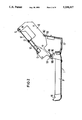
- FIGS. 1-3 illustrate various service positions of the printer, in a longitudinal cross-section through a printer
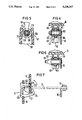
- FIGS. 4 and 5 illustrate a first embodiment of a pivot region for a printer frame in the printer according to FIG. 1, in a longitudinal and lateral cross-section, respectively,
- FIG. 6 illustrates a second embodiment of the pivot region for the printer frame in the printer according to FIG. 1, in a longitudinal cross-section
- FIG. 7 illustrates a cross-section through an attachment device for circuit boards.
- FIGS. 1-3 show different service positions of a printer 1.
- a printer frame 10 is mounted in a holding device 110 of a trough-shaped housing base 11 with its one end, in a pivot region SB.
- the printing frame 10 is mounted via two bearing journals 100. These bearing journals are anchored in the printer frame 10 and project laterally outward. Rubber sleeves 101 surrounding the bearing journals 100 absorb axial forces caused by jolt stresses on the printer frame 10. These rubber sleeves are specially structured for this purpose, as will be explained in the description of FIGS. 4 to 6, infra.
- a depression 111 is arranged in the trough-shaped housing base 11 at an opposite end from the holding device 110. The depression supports the freely pivoting end of the printer frame 10 in an operating position.
- the printer frame 10 furthermore has circuit boards 12. These circuit boards are each attached to the bottom of the printer frame 10 with an attachment device comprising a hinged joint 13 and an attachment screw 14.
- the attachment screw 14 is preferably structured as a captive screw.
- a housing flap 15 and a housing cap 16 are provided to protect the printer frame 10 from dust and other contaminants.
- the housing flap 15 is pivotally mounted in the trough-shaped housing base 11 at one end, at the foot of the holding device 110.
- FIG. 1 shows, in detail, the housing cap 16 arranged or attached on the printer frame 10 or the trough-shaped housing base 11, in a first service position of the printer 1, as well as the housing flap 15 pivoted away from the printer 1.
- the housing flap 16 has a rubber nub 160 and a rib 161.
- the rubber nub 160 and the rib 161 are pressed onto the printer frame 10 or onto the rubber sleeve 101 which surrounds the bearing journal 100 when the housing cap 16 locks against the trough-shaped housing base 11.
- the printer frame 10 is arranged in the trough-shaped housing base 11 free from vibrations.
- FIG. 2 shows in detail, in a second service position of the printer 1, how the printer frame 10 is pivoted away after the housing cap 16 is removed, for example for assembly and maintenance work.
- the printer frame 10 is supported on the housing flap 15, which has been rotated away from the trough-shaped base 11. Differing from FIG. 1, where the printer frame 10 is in the operating position, it is now in an assembly and maintenance position.
- a notch 102 is formed in the printer frame 10 which an edge 150 of the housing flap 15 engages when pivoted away. The notch 102 extends over the entire printer frame width.
- FIG. 3 shows, in detail, in a third service position of the printer 1, how the circuit boards 12 attached on the bottom of the printer frame 10 are pivoted away from the printer frame.
- This third service position serves as an assembly and maintenance position of the printer frame 10.
- the circuit board 12 is attached on the printer frame using the hinged joint 13 and the attachement screw 14 as described referring to FIG. 1, infra.
- the attachment screws 14 are released and the circuit boards, now attached only by the hinged joints 13, are pivoted. While the hinged joint 13 supports the circuit board 12 in a plane parallel to the printer frame 10 in the first and second service positions (see FIGS.
- FIG. 4 shows a longitudinal cross-section of a first embodiment of the pivot region SB.
- the bearing journal 100 is anchored in the printer frame 10, with the rubber sleeve 101 pushed onto it and is protected against axial slip by a locking ring 103.
- the rubber sleeve 101 is provided with a radially projecting crown 104 in the center, which is additionally pressed against a bushing 112 of the holding device 110 by the ribs 161 of the housing cap 16 so that axial forces occurring during any jolt stresses will be absorbed.
- FIG. 5 shows a cross-section of the pivot region SB according to FIG. 4.
- the bearing journal 100 with the rubber sleeve 101 and the crown 104 is locked into the bushing 112 of the holder 110.
- the holding device 110 is provided with two opposite catch projections 113 which project into the pivot region SB of the printer frame 10. These catch projections 113 prevent the bearing journal 110 from being lifted out of the holding device 110 when the printer frame 10 is pivoted.
- the catch projections 113 are formed to be nonelastic. Therefore, when installing the printer frame 10, the crown 104 of the rubber sleeve 101 must be compressed when the bearing journal 100 is pressed forcefully into the holding device 110.
- FIG. 6 shows a longitudinal cross-section of a second embodiment of the pivot region SB.
- a bearing journal 105 is formed in cone shape at the end opposite the printer frame 10 so that the rubber sleeve 101 can be easily pushed onto the bearing journal 105 when securing the rubber sleeve 101.
- FIG. 7 shows, in a side view, how the circuit board 12 is pivotally arranged in the hinged joint 13 and attached on the printer frame 10 in an operating position (i.e., the first service position, see FIG. 1).
- the hinged joint 13 is a plastic injection-molded part. It consists of a square base plate 130, on which a first molded part 131 and a second molded part 132 are arranged on two opposite sides, each projecting and set off from the edge of the base plate 130. At its free end, the first molded part 131, which projects at a slight slant, is bent around at a right angle to the second molded part 132, thereby forming an opening slit 133 to accommodate the circuit board 12.
- a ramp shaped elevation 134 is arranged in the center.
- the ramp shaped elevation 134 becomes flatter in the direction of the first molded part.
- a projecting mandrel 135 is arranged on the frontal surface of the second molded part.
- a depression is provided on the outside surface of the first and second molded part 131, 132, between the base plate 130 and an insertion slant 136. This permits the hinged joint 13 to become locked onto the printer frame since when the hinged joint 13 is pressed into an opening in the printer frame, the depression will engage the edges of the opening.
- the circuit board 12 slides along the ramp-shaped elevation 134 pivoting about the edge of the molded part 131 which is bent at a right angle.
- the mandrel 135 is inserted into a bore 120 of the circuit board 12. The mandrel prevents the circuit board 12 from falling out of the hinged joint 13.
Abstract
Description
Claims (26)
Applications Claiming Priority (1)
| Application Number | Priority Date | Filing Date | Title |
|---|---|---|---|
| DE3934320 | 1989-10-13 |
Publications (1)
| Publication Number | Publication Date |
|---|---|
| US5238317A true US5238317A (en) | 1993-08-24 |
Family
ID=6391464
Family Applications (1)
| Application Number | Title | Priority Date | Filing Date |
|---|---|---|---|
| US07/847,085 Expired - Fee Related US5238317A (en) | 1989-10-13 | 1990-08-10 | Printer providing a freely accessible printer frame |
Country Status (5)
| Country | Link |
|---|---|
| US (1) | US5238317A (en) |
| EP (1) | EP0495785B1 (en) |
| JP (1) | JPH05500338A (en) |
| DE (1) | DE59007957D1 (en) |
| WO (1) | WO1991005667A1 (en) |
Cited By (9)
| Publication number | Priority date | Publication date | Assignee | Title |
|---|---|---|---|---|
| WO1996035160A1 (en) * | 1995-05-01 | 1996-11-07 | Apple Computer, Inc. | Appliance chassis having hingedly mounted section |
| US5710586A (en) * | 1995-01-27 | 1998-01-20 | Tektronix, Inc. | Ink jet printer having webs between stripper fingers |
| US5918089A (en) * | 1996-06-03 | 1999-06-29 | Xerox Corporation | Modular control assembly for xerographic printer |
| US20050141947A1 (en) * | 2003-12-26 | 2005-06-30 | Brother Kogyo Kabushiki Kaisha | Image forming device |
| US20050157013A1 (en) * | 2004-01-21 | 2005-07-21 | Silverbrook Research Pty Ltd | Cradle unit having pivotal electrical contacts for electrically engaging with a pagewidth printhead cartridge |
| US20090096854A1 (en) * | 2007-10-15 | 2009-04-16 | Seiko Epson Corporation | Printer |
| US20110115866A1 (en) * | 2009-11-17 | 2011-05-19 | Canon Finetech Inc. | Image forming apparatus |
| US20120056960A1 (en) * | 2010-08-02 | 2012-03-08 | Avery Dennison Corporation | Two-Piece Hinged Housing and Frame for a Printer |
| US8486693B2 (en) | 2006-05-23 | 2013-07-16 | Bellicum Pharmaceuticals, Inc. | Modified dendritic cells having enhanced survival and immunogenicity and related compositions and methods |
Families Citing this family (3)
| Publication number | Priority date | Publication date | Assignee | Title |
|---|---|---|---|---|
| DE4205773C2 (en) * | 1991-10-08 | 2000-05-25 | Tally Computerdrucker Gmbh | Printers, in particular travel agency printers |
| DE4219682C2 (en) * | 1991-10-08 | 1998-02-26 | Tally Gmbh | Printer for processing individual receipts and receipts in the form of continuous webs |
| CN113586597B (en) * | 2021-09-02 | 2022-04-08 | 深圳辉业科技有限公司 | Duplicator metal hinge convenient to change spare part |
Citations (20)
| Publication number | Priority date | Publication date | Assignee | Title |
|---|---|---|---|---|
| GB486867A (en) * | 1936-12-10 | 1938-06-10 | Olympia Buromaschinenwerke | Typewriter case |
| US3001631A (en) * | 1958-03-07 | 1961-09-26 | Mefina Sa | Portable typewriter |
| US3288500A (en) * | 1963-05-10 | 1966-11-29 | Pneumatiques Caoutchouc Mfg | Flexible joints |
| DE1812660A1 (en) * | 1968-11-29 | 1970-06-11 | Reich K & F Tech Spez | Device for shielding electrotechnical devices against disruptive fields and rays |
| EP0001752A1 (en) * | 1977-09-28 | 1979-05-16 | Trw Inc. | Resilient pivotal joint |
| US4161017A (en) * | 1975-10-15 | 1979-07-10 | Hewlett-Packard Company | Method and apparatus for mounting printed circuit boards |
| EP0020866A1 (en) * | 1979-06-18 | 1981-01-07 | Siemens Aktiengesellschaft | Portable apparatus for testing remote data processing systems |
| DE8106810U1 (en) * | 1981-03-11 | 1981-08-20 | Triumph-Adler Aktiengesellschaft für Büro- und Informationstechnik, 8500 Nürnberg | Device or machine housings |
| JPS5876289A (en) * | 1981-10-31 | 1983-05-09 | Ricoh Co Ltd | Protecting device for recording head |
| US4510345A (en) * | 1981-07-23 | 1985-04-09 | Ing. C. Olivetti & C., S.P.A. | Screen for electrical circuits |
| US4527285A (en) * | 1982-03-29 | 1985-07-02 | International Business Machines Corporation | Pluggable terminal architecture |
| US4531852A (en) * | 1982-03-06 | 1985-07-30 | Kienzle Apparatus GmbH | Printing apparatus of modular construction having a rotatable printhead and plural print stations |
| JPS61252181A (en) * | 1985-05-02 | 1986-11-10 | Canon Inc | Printer |
| EP0226326A2 (en) * | 1985-11-12 | 1987-06-24 | GENICOM Corporation | Printer with tractor drive for webs |
| US4729681A (en) * | 1985-01-25 | 1988-03-08 | Siemens Aktiengesellschaft | Document processing device for single documents separable from a cross-perforated continuous form web |
| JPS63197676A (en) * | 1987-02-12 | 1988-08-16 | Hitachi Ltd | Printer |
| US4828417A (en) * | 1986-10-02 | 1989-05-09 | Osamu Tano | Printer housing |
| US4848941A (en) * | 1987-06-05 | 1989-07-18 | Minolta Camera Kabushiki Kaisha | Thermal printer |
| US4851812A (en) * | 1988-06-07 | 1989-07-25 | Basics Corporation | Portable data system |
| US5026186A (en) * | 1988-07-12 | 1991-06-25 | Citizen Watch Co., Ltd. | Vibrating apparatus including means for absorbing vibration and for locking vibrating unit against movement |
-
1990
- 1990-08-10 JP JP2511177A patent/JPH05500338A/en active Pending
- 1990-08-10 WO PCT/DE1990/000619 patent/WO1991005667A1/en active IP Right Grant
- 1990-08-10 DE DE59007957T patent/DE59007957D1/en not_active Expired - Fee Related
- 1990-08-10 US US07/847,085 patent/US5238317A/en not_active Expired - Fee Related
- 1990-08-10 EP EP90912027A patent/EP0495785B1/en not_active Expired - Lifetime
Patent Citations (20)
| Publication number | Priority date | Publication date | Assignee | Title |
|---|---|---|---|---|
| GB486867A (en) * | 1936-12-10 | 1938-06-10 | Olympia Buromaschinenwerke | Typewriter case |
| US3001631A (en) * | 1958-03-07 | 1961-09-26 | Mefina Sa | Portable typewriter |
| US3288500A (en) * | 1963-05-10 | 1966-11-29 | Pneumatiques Caoutchouc Mfg | Flexible joints |
| DE1812660A1 (en) * | 1968-11-29 | 1970-06-11 | Reich K & F Tech Spez | Device for shielding electrotechnical devices against disruptive fields and rays |
| US4161017A (en) * | 1975-10-15 | 1979-07-10 | Hewlett-Packard Company | Method and apparatus for mounting printed circuit boards |
| EP0001752A1 (en) * | 1977-09-28 | 1979-05-16 | Trw Inc. | Resilient pivotal joint |
| EP0020866A1 (en) * | 1979-06-18 | 1981-01-07 | Siemens Aktiengesellschaft | Portable apparatus for testing remote data processing systems |
| DE8106810U1 (en) * | 1981-03-11 | 1981-08-20 | Triumph-Adler Aktiengesellschaft für Büro- und Informationstechnik, 8500 Nürnberg | Device or machine housings |
| US4510345A (en) * | 1981-07-23 | 1985-04-09 | Ing. C. Olivetti & C., S.P.A. | Screen for electrical circuits |
| JPS5876289A (en) * | 1981-10-31 | 1983-05-09 | Ricoh Co Ltd | Protecting device for recording head |
| US4531852A (en) * | 1982-03-06 | 1985-07-30 | Kienzle Apparatus GmbH | Printing apparatus of modular construction having a rotatable printhead and plural print stations |
| US4527285A (en) * | 1982-03-29 | 1985-07-02 | International Business Machines Corporation | Pluggable terminal architecture |
| US4729681A (en) * | 1985-01-25 | 1988-03-08 | Siemens Aktiengesellschaft | Document processing device for single documents separable from a cross-perforated continuous form web |
| JPS61252181A (en) * | 1985-05-02 | 1986-11-10 | Canon Inc | Printer |
| EP0226326A2 (en) * | 1985-11-12 | 1987-06-24 | GENICOM Corporation | Printer with tractor drive for webs |
| US4828417A (en) * | 1986-10-02 | 1989-05-09 | Osamu Tano | Printer housing |
| JPS63197676A (en) * | 1987-02-12 | 1988-08-16 | Hitachi Ltd | Printer |
| US4848941A (en) * | 1987-06-05 | 1989-07-18 | Minolta Camera Kabushiki Kaisha | Thermal printer |
| US4851812A (en) * | 1988-06-07 | 1989-07-25 | Basics Corporation | Portable data system |
| US5026186A (en) * | 1988-07-12 | 1991-06-25 | Citizen Watch Co., Ltd. | Vibrating apparatus including means for absorbing vibration and for locking vibrating unit against movement |
Non-Patent Citations (4)
| Title |
|---|
| "Combined Cover Support & Interlock Switch", IBM Tech. Discl. Bulletin, vol. 27, No. 1B, Jun. 1984, pp. 565*14 566. |
| "Six Point Hinge Mechanism" IBM Technical Disclosure Bulletin, vol. 28, No. 6, Nov. 1985 pp. 2476-2477. |
| Combined Cover Support & Interlock Switch , IBM Tech. Discl. Bulletin, vol. 27, No. 1B, Jun. 1984, pp. 565*14 566. * |
| Six Point Hinge Mechanism IBM Technical Disclosure Bulletin, vol. 28, No. 6, Nov. 1985 pp. 2476 2477. * |
Cited By (22)
| Publication number | Priority date | Publication date | Assignee | Title |
|---|---|---|---|---|
| US5710586A (en) * | 1995-01-27 | 1998-01-20 | Tektronix, Inc. | Ink jet printer having webs between stripper fingers |
| US5949462A (en) * | 1995-01-27 | 1999-09-07 | Tektronix, Inc. | Ink jet printer |
| US5784251A (en) * | 1995-05-01 | 1998-07-21 | Apple Computer, Inc. | Appliance chassis having hingedly mounted section |
| WO1996035160A1 (en) * | 1995-05-01 | 1996-11-07 | Apple Computer, Inc. | Appliance chassis having hingedly mounted section |
| US5918089A (en) * | 1996-06-03 | 1999-06-29 | Xerox Corporation | Modular control assembly for xerographic printer |
| US7246963B2 (en) * | 2003-12-26 | 2007-07-24 | Brother Kogyo Kabushiki Kaisha | Image forming device |
| US20050141947A1 (en) * | 2003-12-26 | 2005-06-30 | Brother Kogyo Kabushiki Kaisha | Image forming device |
| US20080218538A1 (en) * | 2004-01-21 | 2008-09-11 | Silverbrook Research Pty Ltd | Cradle Unit For A Print Engine Having A Maintenance Drive Assembly |
| US7971978B2 (en) | 2004-01-21 | 2011-07-05 | Silverbrook Research Pty Ltd | Refillable ink cartridge with ink bypass channel for refilling |
| US20080211888A1 (en) * | 2004-01-21 | 2008-09-04 | Silverbrook Research Pty Ltd | Ink Storage Compartment With Bypass Fluid Path Structures |
| US20050157013A1 (en) * | 2004-01-21 | 2005-07-21 | Silverbrook Research Pty Ltd | Cradle unit having pivotal electrical contacts for electrically engaging with a pagewidth printhead cartridge |
| US7384135B2 (en) * | 2004-01-21 | 2008-06-10 | Silverbrook Research Pty Ltd | Cradle unit having pivotal electrical contacts for electrically engaging with a pagewidth printhead cartridge |
| US7537315B2 (en) | 2004-01-21 | 2009-05-26 | Silverbrook Research Pty Ltd | Cradle unit for a print engine having a maintenance drive assembly |
| US7658483B2 (en) | 2004-01-21 | 2010-02-09 | Silverbrook Research Pty Ltd | Ink storage compartment with bypass fluid path structures |
| US20100134575A1 (en) * | 2004-01-21 | 2010-06-03 | Silverbrook Research Pty Ltd | Refillable ink cartridge with ink bypass channel for refilling |
| US8486693B2 (en) | 2006-05-23 | 2013-07-16 | Bellicum Pharmaceuticals, Inc. | Modified dendritic cells having enhanced survival and immunogenicity and related compositions and methods |
| US20090096854A1 (en) * | 2007-10-15 | 2009-04-16 | Seiko Epson Corporation | Printer |
| US8197060B2 (en) * | 2007-10-15 | 2012-06-12 | Seiko Epson Corporation | Printer opening and closing mechanism which prevents interference of the platen and the inkjet head |
| US8430504B2 (en) | 2007-10-15 | 2013-04-30 | Seiko Epson Corporation | Printer opening and closing mechanism which prevents interference of the platen and the inkjet head |
| US8434862B2 (en) * | 2009-11-17 | 2013-05-07 | Canon Finetech Inc. | Image forming apparatus |
| US20110115866A1 (en) * | 2009-11-17 | 2011-05-19 | Canon Finetech Inc. | Image forming apparatus |
| US20120056960A1 (en) * | 2010-08-02 | 2012-03-08 | Avery Dennison Corporation | Two-Piece Hinged Housing and Frame for a Printer |
Also Published As
| Publication number | Publication date |
|---|---|
| EP0495785A1 (en) | 1992-07-29 |
| WO1991005667A1 (en) | 1991-05-02 |
| EP0495785B1 (en) | 1994-12-07 |
| DE59007957D1 (en) | 1995-01-19 |
| JPH05500338A (en) | 1993-01-28 |
Similar Documents
| Publication | Publication Date | Title |
|---|---|---|
| US5238317A (en) | Printer providing a freely accessible printer frame | |
| US7852637B2 (en) | Bi-positional expansion card retainer | |
| US4896777A (en) | Lock and shock mounted device for computer disk drive | |
| US6535390B1 (en) | Securing device and electronic appliance assembly applying the same | |
| US7484702B2 (en) | Temporary clamping structure for electronics | |
| JPH04267591A (en) | Device for fixation of electronic apparatus to mounting wall | |
| EP2212155B2 (en) | Mounting construction for an outside mirror unit | |
| US6477050B1 (en) | Tilt-away processor retention module with hold-down screw device | |
| EP0363462A1 (en) | A mounting structure for an electric motor. | |
| GB2280874A (en) | Exchangeable line-printhead in thermal printer. | |
| US4646383A (en) | Synthetic resin spacer for connecting parallel plates at predetermined space | |
| US4668036A (en) | Large picture display device | |
| US20030227239A1 (en) | Lockable bezel | |
| US5445450A (en) | Circuit board support | |
| KR850002820Y1 (en) | Computer printer | |
| JPH04228911A (en) | Loading device | |
| US5141342A (en) | Mounting mechanism for ribbon cassette | |
| JP2561688Y2 (en) | Rail mounting device for electronic equipment | |
| KR0122629Y1 (en) | Lamp structure | |
| JP2823503B2 (en) | Printed circuit board mounting device | |
| KR0127847Y1 (en) | Optical cable connector fixing device | |
| JP2021172297A (en) | On-vehicle electronic device | |
| JPH0427197Y2 (en) | ||
| EP0337638A2 (en) | Motor vehicle lamp assembly | |
| KR100198037B1 (en) | Fixture for battery |
Legal Events
| Date | Code | Title | Description |
|---|---|---|---|
| AS | Assignment |
Owner name: SIEMENS AKTIENGESELLSCHAFT, GERMANY Free format text: ASSIGNMENT OF ASSIGNORS INTEREST.;ASSIGNORS:BOHMER, GEORG;IRRO, OTMAR;REEL/FRAME:006189/0653 Effective date: 19920414 |
|
| FEPP | Fee payment procedure |
Free format text: PAYOR NUMBER ASSIGNED (ORIGINAL EVENT CODE: ASPN); ENTITY STATUS OF PATENT OWNER: LARGE ENTITY |
|
| AS | Assignment |
Owner name: INKJET SYSTEMS GMBH & CO. KG, GERMANY Free format text: ASSIGNMENT OF ASSIGNORS INTEREST;ASSIGNOR:EASTMAN KODAK COMPANY;REEL/FRAME:007201/0578 Effective date: 19940926 |
|
| AS | Assignment |
Owner name: EASTMAN KODAK COMPANY, NEW YORK Free format text: CORRECTION OF RECORDATION OF ASSIGNMENT RECORDED AT REEL 7201, FRAMES 578-605;ASSIGNOR:INKJET SYSTEMS GMBH 7 CO.KG;REEL/FRAME:007512/0687 Effective date: 19940926 |
|
| FEPP | Fee payment procedure |
Free format text: PAYER NUMBER DE-ASSIGNED (ORIGINAL EVENT CODE: RMPN); ENTITY STATUS OF PATENT OWNER: LARGE ENTITY Free format text: PAYOR NUMBER ASSIGNED (ORIGINAL EVENT CODE: ASPN); ENTITY STATUS OF PATENT OWNER: LARGE ENTITY |
|
| FPAY | Fee payment |
Year of fee payment: 4 |
|
| REMI | Maintenance fee reminder mailed | ||
| LAPS | Lapse for failure to pay maintenance fees | ||
| FP | Lapsed due to failure to pay maintenance fee |
Effective date: 20010824 |
|
| STCH | Information on status: patent discontinuation |
Free format text: PATENT EXPIRED DUE TO NONPAYMENT OF MAINTENANCE FEES UNDER 37 CFR 1.362 |