US5234167A - One-piece foamer nozzle - Google Patents
One-piece foamer nozzle Download PDFInfo
- Publication number
- US5234167A US5234167A US07/437,550 US43755089A US5234167A US 5234167 A US5234167 A US 5234167A US 43755089 A US43755089 A US 43755089A US 5234167 A US5234167 A US 5234167A
- Authority
- US
- United States
- Prior art keywords
- nozzle
- barrel portion
- outer barrel
- orifice
- annular formation
- Prior art date
- Legal status (The legal status is an assumption and is not a legal conclusion. Google has not performed a legal analysis and makes no representation as to the accuracy of the status listed.)
- Expired - Lifetime
Links
Images


Classifications
-
- B—PERFORMING OPERATIONS; TRANSPORTING
- B05—SPRAYING OR ATOMISING IN GENERAL; APPLYING FLUENT MATERIALS TO SURFACES, IN GENERAL
- B05B—SPRAYING APPARATUS; ATOMISING APPARATUS; NOZZLES
- B05B7/00—Spraying apparatus for discharge of liquids or other fluent materials from two or more sources, e.g. of liquid and air, of powder and gas
- B05B7/0018—Spraying apparatus for discharge of liquids or other fluent materials from two or more sources, e.g. of liquid and air, of powder and gas with devices for making foam
- B05B7/005—Spraying apparatus for discharge of liquids or other fluent materials from two or more sources, e.g. of liquid and air, of powder and gas with devices for making foam wherein ambient air is aspirated by a liquid flow
- B05B7/0056—Spraying apparatus for discharge of liquids or other fluent materials from two or more sources, e.g. of liquid and air, of powder and gas with devices for making foam wherein ambient air is aspirated by a liquid flow with disturbing means promoting mixing, e.g. balls, crowns
Definitions
- the present invention relates to a one-piece foamer nozzle which is moveable between an "OFF" position and a "FOAM” position and which is mounted on the front end of a trigger sprayer.
- foam dispensing devices which are mountable on a trigger sprayer.
- Such devices include nozzle assemblies which are mountable at the front end of the trigger sprayer. All these devices include a foam generating chamber, means for admitting air into the 15 chamber, and an outlet from the chamber. In some of these devices a screen is provided for assisting in the generation of foam.
- a trigger operated foam dispensing device which utilizes a foam generating chamber and a perforated wall through which foam is ejected is disclosed in the Tada U.S. Pat. No. 4,350,298.
- the trigger operated foam dispensing device includes a nozzle cap with an outlet wall having a plurality of arms constituting an obstacle wall against which liquid from a spray or stream outlet orifice collides, thereby to mix with air in the nozzle cap to form foam which exits the nozzle cap through three or more openings formed between the arms of the outlet wall.
- a two position foam nozzle assembly for use with a trigger sprayer is disclosed in Japanese Patent Publication No. 133358/1981.
- a foam generating chamber is provided that is positioned forwardly of an orifice within the nozzle assembly and foam created in the foam generating chamber passes into a foam accumulating chamber, the two chambers being separated by three spokes or a Y formation.
- Japanese Patent Publication 63-51670 published in 1988, discloses a foam nozzle assembly wherein a foam generating chamber is positioned in front of an orifice within the inside of the nozzle assembly and foam exits directly from the foam generating chamber.
- a nozzle which is capable of selectively dispensing a liquid product as a foam or a spray.
- an annular foamer member is moveable axially of the nozzle axis from a position adjacent an outlet orifice in the nozzle body to a position spaced forwardly of the nozzle orifice where the spray from the nozzle orifice can engage an inside surface of a sleeve of the foamer member for making foam.
- a nozzle including a cylinder defining a foam generating chamber.
- An orifice is located in the nozzle at the entrance end of the foam generating chamber.
- One or more air passageways within the nozzle allow air to enter into the entrance end of the foam generating chamber.
- a spray of liquid from the orifice into a foam generating chamber mixes with the air entering from both axial ends of the cylindrical foam generating chamber to form foam.
- the Corsette U.S. Pat. No. 4,779,803 discloses a manually actuated liquid sprayer which is adapted to generate foam when a ported movable element is moved to an axially extended position.
- the element has a central cylindrical port therein larger than an outlet orifice positioned behind the element. Liquid sprayed from the orifice engages the cylindrical wall of the central port to create foam when the element is extended.
- a trigger sprayer nozzle having an outer shape similar to the shape of the one piece foamer nozzle of the present invention is illustrated in the Verhees U.S. Pat. No. 293,929.
- the one-piece foamer nozzle of the present invention differs from the previously proposed foamer nozzle assemblies and, in particular, from the one-piece foamer nozzle illustrated in U.S. Pat. No. 293,929 by providing, in addition to an outer barrel portion in the nozzle which forms a foam generating chamber, an annular formation extending a short distance forwardly from a wall within the outer barrel portion which has an orifice from which liquid is sprayed in a conical spray into and against the inner surface of the outer barrel portion forming the foam generating chamber.
- this short annular formation increases, enhances or facilitates the generation of foam, as a result of some of the conical spray from the outlet orifice in the nozzle hitting the inner surface of the short annular formation and causing greater turbulence in the outer barrel portion.
- the portion of the conical spray that impinges upon the inner surface of the short annular portion will be deflected into the rest of the conical spray that passes out of the short annular portion to impinge upon the inner surface of the outer barrel portion, thereby, increasing the cross flow and turbulence of liquid and air in the foam generating chamber to create foam.
- a one-piece foamer nozzle comprising an inner cap portion, an outer barrel portion, and an internal wall inside the nozzle between the cap portion and the barrel portion.
- the internal wall has a central orifice therethrough.
- the cap portion has a cavity and structure in the cavity for receiving and mating with a nose bushing mounted to the front end of a trigger sprayer.
- the structure has passageways, adapted to register with passageways on the nose bushing when the nozzle is rotated to a predetermined position on the nose bushing to direct liquid in a swirl, whereby a conical spray exits the central orifice when the trigger sprayer is operated.
- the outer barrel portion has an inner, generally cylindrical, wall surface.
- the nozzle further has a short annular formation coaxial with the orifice and fixed to and extending outwardly from the internal wall around the orifice.
- the short annular formation has an axial extent from the internal wall sufficient to cause a generally cylindrical inner surface of the annular formation to interfere with at least a portion of the conical spray exiting from the orifice upon operation of the trigger sprayer, whereby some of the conically sprayed liquid engaging the inner surface of the short annular formation will be deflected into the path of the conical spray of liquid flowing toward the inner, generally cylindrical, wall surface of the outer barrel portion, thereby to enhance turbulence and mixing of air and liquid in the outer barrel portion to enhance the generation of foam.
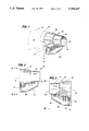
- FIG. 1 is a fragmentary prospective view, in phantom, of the upper front end of a trigger sprayer and a perspective view of the one-piece foamer nozzle of the present invention.
- FIG. 2 is a left side elevational view of the foamer nozzle shown in FIG. 1.
- FIG. 3 is a right side elevational view of the foamer nozzle shown in FIG. 1.
- FIG. 4 is a rear elevational view of the foamer nozzle shown in FIG. 1 and is taken along line 4--4 of FIG. 2.
- FIG. 5 is a front elevational view of the foamer nozzle shown in FIG. 1, is taken along line 5--5 of FIG. 3, and shows a short cylindrical or annular formation situated inside an outer barrel portion of the one-piece foamer nozzle.
- FIG. 6 is a sectional view taken along line 6--6 of FIG. 4 and shows the short annular formation extending forwardly from an interior wall within the one-piece foamer nozzle and into the outer barrel portion.
- FIG. 1 a trigger operated liquid dispensing device or trigger sprayer 10 which has a body 12, including a front end 14 with an outer orifice not shown.
- the trigger sprayer 10 includes a pumping system or mechanism (not shown) mounted within the body 12.
- the pumping system is operated by a trigger 16 pivotally mounted to part of the body 12 (not shown).
- a one-piece foamer nozzle 20 constructed according to the teachings of the present invention is mounted to the nose bushing (not shown) which has been assembled into an outer opening at the front end 14 of the body 12 of the trigger sprayer 10 and is adapted to be rotated on the nose bushing from an off position (the position shown in the Figures) to a foam position (where spray indicia on the outer surface of the nozzle 20 is in an upper horizontal position) where pumping of liquid from a container (not shown) to which the sprayer 10 is attached by squeezing of the trigger 16 of the trigger sprayer 10 will result in the generation of foam in the nozzle 20 and the dispensing of foam from an outlet end 22 of an outer barrel portion 24 of the nozzle 20.
- the outer barrel portion 24 has an inner, smooth, generally cylindrical wall surface 26 therein in which foam is generated.
- the nozzle 20 further includes an inner cap portion 28 having a cavity 30 (FIGS. 4 and 6) in which is received the nose bushing (not shown) of the type disclosed in U.S. Pat. No. 4,730,775, for example, the disclosure of which is incorporated herein by reference, for mounting the cap portion 28 on the nose bushing.
- the nose bushing (not shown) of the type disclosed in U.S. Pat. No. 4,730,775, for example, the disclosure of which is incorporated herein by reference, for mounting the cap portion 28 on the nose bushing.
- a radial flange 32 which extends from and is integral with a rear end 34 of the inner cap portion 28.
- a thumb or finger engageable axially extending flange 36 extends axially forwardly from the radially extending flange 32.
- the outer barrel portion 24 has at least one air inlet opening 38 therein located adjacent the junction between the outer barrel portion 24 and the inner cap portion 28.
- the cap portion 28 has a rounded generally inverted triangular configuration with a generally horizontal top surface 40 which is shown in FIG. 5 and has indicia 42 thereon in the form of the word "OFF".
- Another surface 43 (FIG. 3) has spray indicating indicia 45 in the form of a group of small circles (representing bubbles) inside a "V" on it's side (representing a conical spray of foam).
- an internal wall 44 which separates the inner cap portion 28 from the outer barrel portion 24 and which has a central orifice 46 therethrough.
- FIG. 4 is a rear elevational back or end view of the nozzle 20 and shows a generally cylindrical cavity 48 in the cap portion 28 and first and second stop members 51 and 52 which limit the rotation of the nozzle 20 on the nose bushing (not shown).
- the stops 51 and 52 are positioned to engage respective stops or bosses on the nose bushing (not shown) at the two rotational positions of the nozzle 20.
- the inner cap portion 28 also has an internal cylinder 56 extending rearwardly from said internal wall 44 which is adapted to mate with a cylindrical projection on the nose bushing (not shown) whereby liquid can be directed into the internal cylinder 56 through passageways 61 and 62 formed in the internal cylinder which mate or register with passageways (not shown) in the nose bushing (not shown) so that liquid is directed to a space 66 in front of the internal wall 44 and caused to flow in that space 66 in a swirl so that swirling liquid will flow through the central orifice in the internal wall 44 and be ejected from an outlet end 68 (FIG. 6) of the orifice 46 in a conical spray pattern subtending an angle between 30° and 50°.
- an internal cylinder 56 extending rearwardly from said internal wall 44 which is adapted to mate with a cylindrical projection on the nose bushing (not shown) whereby liquid can be directed into the internal cylinder 56 through passageways 61 and 62 formed in the internal cylinder which mate or register with passageways
- the outer barrel portion 24 has the smooth inner cylindrical wall surface 26 against which liquid exiting the outlet end 68 of the orifice 46 in a spray pattern can impinge and be deflected to mix with air.
- a short cylindrical or annular formation 70 is provided inside the outer barrel portion 24 coaxial with the central orifice 46 and extending outwardly from a front surface 72 of the internal wall 44 a short distance.
- the short annular formation 70 is designed to have an axial extent sufficient so that at least some of the conical spray exiting from the outlet end 68 (FIG. 6) of the orifice 46 impinges upon an inner wall surface 74 of the short annular formation 70 so that liquid is deflected therefrom toward the inner wall surface 26 of the outer barrel portion 24 and intersecting the path of other conically sprayed liquid from the outlet end 68 (FIG. 6) of the orifice 46 or deflected from the inner wall surface 74 of the short annular formation 70, thereby to create greater mixing and turbulence in the liquid droplets and air inside the foam generating chamber (defined within the outer barrel portion 24) than would be obtained if the short annular formation 70 was not provided.
- the short annular formation 70 should be only so long as to prevent some of the conical spray from impinging directly upon the inside surface of the outer barrel portion 24 and not so long as to have all the conical spray impinging upon the inner wall surface 74 with mixing taking place solely within the short annular formation 70.
- the short annular formation 70 performs two other functions, namely: (1) by standing higher than or forward of the air inlet opening 38, it forces air to circulate around the outer diameter of this annular wall formation 70 creating a more uniform mixture of air with the conical spray thereby enhancing the foam characteristics; and (2) by standing higher than or forward of the air inlet opening 38, it prevents any foreign spray direction from outlet end 68 of the orifice 46 going through the air inlet opening 38.
- the axial extent of the internal wall 74 of the short annular formation was approximately 0.064 inches and the axial extent of the foaming chamber, inner wall surface 26, within the outer barrel portion 24 from the internal wall 44 to the outer end 22 of the outer barrel portion 24 was approximately 0.260 inches.
- the diameter of the central orifice 46 was approximately 0.024 inches and the inner diameter of the short annular formation 70 was 0.103 inches.
- the outer diameter of the short annular formation 70 was approximately 0.167 inches and the inner diameter of the outer barrel portion 24 (inner wall surface 26) was approximately 0.234 inches.
- the cone of the spray exiting from the outlet end 68 of the orifice 46 subtended an angle of between approximately 30° and 50°.
- One air inlet opening 38 (FIG. 3) was provided having a generally square shape with a dimension of approximately 0.050 inch per side.
- an inner forward surface 80 thereof (FIG. 6) is tapered at an angle of approximately 15° for a length of approximately 0.058 inches as shown in FIG. 6.
- the foamer nozzle of the present invention has a number of advantages, some of which have been described herein, for example improved foam generation, and others of which are inherent in the foamer nozzle. Also modifications can be made to the foamer nozzle described herein without departing from the spirit or scope of the invention as defined in the accompanying claims. Accordingly, the scope of the present invention is only to be limited as necessitated by the accompanying claims.
Abstract
Description
Claims (9)
Priority Applications (1)
| Application Number | Priority Date | Filing Date | Title |
|---|---|---|---|
| US07/437,550 US5234167A (en) | 1989-11-16 | 1989-11-16 | One-piece foamer nozzle |
Applications Claiming Priority (1)
| Application Number | Priority Date | Filing Date | Title |
|---|---|---|---|
| US07/437,550 US5234167A (en) | 1989-11-16 | 1989-11-16 | One-piece foamer nozzle |
Publications (1)
| Publication Number | Publication Date |
|---|---|
| US5234167A true US5234167A (en) | 1993-08-10 |
Family
ID=23736905
Family Applications (1)
| Application Number | Title | Priority Date | Filing Date |
|---|---|---|---|
| US07/437,550 Expired - Lifetime US5234167A (en) | 1989-11-16 | 1989-11-16 | One-piece foamer nozzle |
Country Status (1)
| Country | Link |
|---|---|
| US (1) | US5234167A (en) |
Cited By (9)
| Publication number | Priority date | Publication date | Assignee | Title |
|---|---|---|---|---|
| US5366160A (en) * | 1994-03-09 | 1994-11-22 | Calmar Inc. | Foamer nozzle with looped rib flow disrupters |
| EP0719590A1 (en) * | 1994-12-29 | 1996-07-03 | Elf Antar France | Apparatus for spraying a mixture of air and liquid |
| US5645223A (en) * | 1995-10-19 | 1997-07-08 | Hull; Harold L. | Liquid/foam/mixing/aeration adapter apparatus |
| US5755384A (en) * | 1995-08-01 | 1998-05-26 | Contico International, Inc. | Dispenser with selectable discharge nozzle |
| US6997397B1 (en) | 2003-04-08 | 2006-02-14 | Continental Afa Dispensing Company | Trigger sprayer nozzle |
| US20100089951A1 (en) * | 2008-10-14 | 2010-04-15 | Yates James M | Dispensing tube assembly and foam generator for coaxial tubes |
| JP2013081927A (en) * | 2011-09-30 | 2013-05-09 | Yoshino Kogyosho Co Ltd | Liquid sprayer |
| US8656909B2 (en) | 2005-07-28 | 2014-02-25 | Glaxo Group Limited | Nozzle for a nasal inhaler |
| US10882227B2 (en) * | 2018-05-23 | 2021-01-05 | Faurecia Interior Systems, Inc. | Foam mix-head bushing and method of manufacturing a vehicle interior panel with the bushing |
Citations (12)
| Publication number | Priority date | Publication date | Assignee | Title |
|---|---|---|---|---|
| US4350298A (en) * | 1979-08-16 | 1982-09-21 | Canyon Corporation | Foam dispenser |
| US4646973A (en) * | 1985-08-07 | 1987-03-03 | The Clorox Company | Impingement foamer |
| US4669665A (en) * | 1984-10-11 | 1987-06-02 | Specialty Packaging Licensing Company | Nozzle |
| JPS6351670A (en) * | 1986-08-21 | 1988-03-04 | Shoichi Tanaka | Solid-state image pickup device |
| US4730775A (en) * | 1986-01-10 | 1988-03-15 | Afa Division Of Waynesboro Textiles, Inc. | Two piece foamer nozzle assembly |
| US4767060A (en) * | 1987-06-05 | 1988-08-30 | Specialty Packaging Licensing Company | Nozzle |
| US4768717A (en) * | 1987-02-12 | 1988-09-06 | Specialty Packaging Licensing Company | Nozzle |
| US4779803A (en) * | 1986-08-11 | 1988-10-25 | Calmar, Inc. | Manually actuated liquid sprayer |
| JPH01101661A (en) * | 1987-10-15 | 1989-04-19 | Matsushita Electric Ind Co Ltd | Manufacture of electrical contact |
| JPH01101662A (en) * | 1987-09-18 | 1989-04-19 | Sgs Thomson Microelectron Inc | Manufacture of cmos device |
| JPH01203065A (en) * | 1988-02-05 | 1989-08-15 | Atsushi Tada | Spinner for dispenser and dispenser |
| JPH0283053A (en) * | 1988-09-21 | 1990-03-23 | Atsushi Tada | Spinner for dispenser, liquid flow switching mechanism and dispenser |
-
1989
- 1989-11-16 US US07/437,550 patent/US5234167A/en not_active Expired - Lifetime
Patent Citations (12)
| Publication number | Priority date | Publication date | Assignee | Title |
|---|---|---|---|---|
| US4350298A (en) * | 1979-08-16 | 1982-09-21 | Canyon Corporation | Foam dispenser |
| US4669665A (en) * | 1984-10-11 | 1987-06-02 | Specialty Packaging Licensing Company | Nozzle |
| US4646973A (en) * | 1985-08-07 | 1987-03-03 | The Clorox Company | Impingement foamer |
| US4730775A (en) * | 1986-01-10 | 1988-03-15 | Afa Division Of Waynesboro Textiles, Inc. | Two piece foamer nozzle assembly |
| US4779803A (en) * | 1986-08-11 | 1988-10-25 | Calmar, Inc. | Manually actuated liquid sprayer |
| JPS6351670A (en) * | 1986-08-21 | 1988-03-04 | Shoichi Tanaka | Solid-state image pickup device |
| US4768717A (en) * | 1987-02-12 | 1988-09-06 | Specialty Packaging Licensing Company | Nozzle |
| US4767060A (en) * | 1987-06-05 | 1988-08-30 | Specialty Packaging Licensing Company | Nozzle |
| JPH01101662A (en) * | 1987-09-18 | 1989-04-19 | Sgs Thomson Microelectron Inc | Manufacture of cmos device |
| JPH01101661A (en) * | 1987-10-15 | 1989-04-19 | Matsushita Electric Ind Co Ltd | Manufacture of electrical contact |
| JPH01203065A (en) * | 1988-02-05 | 1989-08-15 | Atsushi Tada | Spinner for dispenser and dispenser |
| JPH0283053A (en) * | 1988-09-21 | 1990-03-23 | Atsushi Tada | Spinner for dispenser, liquid flow switching mechanism and dispenser |
Cited By (12)
| Publication number | Priority date | Publication date | Assignee | Title |
|---|---|---|---|---|
| US5366160A (en) * | 1994-03-09 | 1994-11-22 | Calmar Inc. | Foamer nozzle with looped rib flow disrupters |
| AU679826B2 (en) * | 1994-03-09 | 1997-07-10 | Calmar Inc. | Foamer nozzle with looped rib flow disrupters |
| EP0719590A1 (en) * | 1994-12-29 | 1996-07-03 | Elf Antar France | Apparatus for spraying a mixture of air and liquid |
| FR2728808A1 (en) * | 1994-12-29 | 1996-07-05 | Elf Antar France | DEVICE FOR PROJECTING A MIXTURE OF AIR AND LIQUID |
| US5755384A (en) * | 1995-08-01 | 1998-05-26 | Contico International, Inc. | Dispenser with selectable discharge nozzle |
| US5645223A (en) * | 1995-10-19 | 1997-07-08 | Hull; Harold L. | Liquid/foam/mixing/aeration adapter apparatus |
| US6997397B1 (en) | 2003-04-08 | 2006-02-14 | Continental Afa Dispensing Company | Trigger sprayer nozzle |
| US8656909B2 (en) | 2005-07-28 | 2014-02-25 | Glaxo Group Limited | Nozzle for a nasal inhaler |
| US20100089951A1 (en) * | 2008-10-14 | 2010-04-15 | Yates James M | Dispensing tube assembly and foam generator for coaxial tubes |
| US8286836B2 (en) | 2008-10-14 | 2012-10-16 | Gojo Industries, Inc. | Dispensing tube assembly and foam generator for coaxial tubes |
| JP2013081927A (en) * | 2011-09-30 | 2013-05-09 | Yoshino Kogyosho Co Ltd | Liquid sprayer |
| US10882227B2 (en) * | 2018-05-23 | 2021-01-05 | Faurecia Interior Systems, Inc. | Foam mix-head bushing and method of manufacturing a vehicle interior panel with the bushing |
Similar Documents
| Publication | Publication Date | Title |
|---|---|---|
| US4925106A (en) | Foam-off nozzle assembly with barrel screen insert for use in a trigger sprayer | |
| US5397060A (en) | Foam-spray-off trigger sprayer | |
| US5678765A (en) | Foam/spray nozzle assembly for trigger sprayer | |
| US4890792A (en) | Nozzle assembly | |
| US4779803A (en) | Manually actuated liquid sprayer | |
| US5738282A (en) | Pump sprayer nozzle for producing a solid spray pattern | |
| US4730775A (en) | Two piece foamer nozzle assembly | |
| US7222802B2 (en) | Dual sprayer with external mixing chamber | |
| US5647539A (en) | Foamer nozzle assembly for trigger sprayer | |
| US5755384A (en) | Dispenser with selectable discharge nozzle | |
| US5234167A (en) | One-piece foamer nozzle | |
| US4883227A (en) | Foamer nozzle assembly with air passageway | |
| US5295628A (en) | Discharge nozzle for media | |
| JP2520340B2 (en) | Fluid ejection device | |
| AU625077C (en) | Foam-off nozzle assembly with barrel screen insert for use in a trigger sprayer | |
| JP2602636Y2 (en) | Nebulizer | |
| MXPA97001437A (en) | Spray nozzle with pump to produce solid aspers unpatron |
Legal Events
| Date | Code | Title | Description |
|---|---|---|---|
| AS | Assignment |
Owner name: AFA PRODUCTS, INC., A CORP. OF DE, NORTH CAROLINA Free format text: ASSIGNMENT OF ASSIGNORS INTEREST.;ASSIGNOR:MARTIN, DOUGLAS S.;REEL/FRAME:005222/0264 Effective date: 19891219 |
|
| STCF | Information on status: patent grant |
Free format text: PATENTED CASE |
|
| REMI | Maintenance fee reminder mailed | ||
| FPAY | Fee payment |
Year of fee payment: 4 |
|
| SULP | Surcharge for late payment | ||
| AS | Assignment |
Owner name: AFA ACQUISITION CORP., NORTH CAROLINA Free format text: ASSIGNMENT OF ASSIGNORS INTEREST;ASSIGNOR:AFA PRODUCTS, INC.;REEL/FRAME:008709/0024 Effective date: 19970724 |
|
| FEPP | Fee payment procedure |
Free format text: PAYOR NUMBER ASSIGNED (ORIGINAL EVENT CODE: ASPN); ENTITY STATUS OF PATENT OWNER: LARGE ENTITY |
|
| AS | Assignment |
Owner name: NATIONSCREDIT COMMERCIAL CORPORATION, CONNECTICUT Free format text: SECURITY INTEREST;ASSIGNOR:AFA ACQUISITION CORP.;REEL/FRAME:008907/0242 Effective date: 19970729 |
|
| AS | Assignment |
Owner name: NATIONSCREDIT COMMERICAL CORPORATION, CONNECTICUT Free format text: SECURITY INTEREST;ASSIGNORS:APC HOLDINGS, INC., A DELAWARE CORPORATION;AFA HOLDINGS CO., A DELAWARE CORPORATION;AFA PRODUCTS, INC., A DELAWARE CORPORATION;AND OTHERS;REEL/FRAME:008967/0777 Effective date: 19980204 |
|
| AS | Assignment |
Owner name: AFA PRODUCTS, INC., NORTH CAROLINA Free format text: CHANGE OF NAME;ASSIGNOR:AFA ACQUISITION CORPORATION;REEL/FRAME:009350/0723 Effective date: 19970729 |
|
| AS | Assignment |
Owner name: AFA PRODUCTS, INC., NORTH CAROLINA Free format text: RELEASE OF SECURITY AGREEMENT;ASSIGNOR:NATIONSCREDIT COMMERCIAL CORPORATION;REEL/FRAME:009605/0214 Effective date: 19980929 |
|
| AS | Assignment |
Owner name: FIRST UNION NATIONAL BANK, NORTH CAROLINA Free format text: SECURITY INTEREST;ASSIGNOR:AFA PRODUCTS, INC.;REEL/FRAME:011097/0614 Effective date: 19980929 |
|
| AS | Assignment |
Owner name: CIT GROUP/BUISNESS CREDIT, INC., THE, NEW YORK Free format text: ASSIGNMENT OF ASSIGNORS INTEREST;ASSIGNOR:AFA PRODUCTS, INC.;REEL/FRAME:011410/0659 Effective date: 20001016 |
|
| REMI | Maintenance fee reminder mailed | ||
| FPAY | Fee payment |
Year of fee payment: 8 |
|
| SULP | Surcharge for late payment |
Year of fee payment: 7 |
|
| AS | Assignment |
Owner name: AFA PRODUCTS, INC., NEW YORK Free format text: RELEASE OF SECURITY INTEREST IN PATENTS;ASSIGNOR:FIRST UNION NATIONAL BANK;REEL/FRAME:012683/0333 Effective date: 20001016 |
|
| AS | Assignment |
Owner name: CIT GROUP,THE/BUSINESS CREDIT, INC. AS AGENT FOR T Free format text: SECURITY INTEREST;ASSIGNOR:AFA PRODUCTS, INC.;REEL/FRAME:012683/0933 Effective date: 20020315 |
|
| FEPP | Fee payment procedure |
Free format text: PAT HOLDER NO LONGER CLAIMS SMALL ENTITY STATUS, ENTITY STATUS SET TO UNDISCOUNTED (ORIGINAL EVENT CODE: STOL); ENTITY STATUS OF PATENT OWNER: LARGE ENTITY Free format text: PAYOR NUMBER ASSIGNED (ORIGINAL EVENT CODE: ASPN); ENTITY STATUS OF PATENT OWNER: LARGE ENTITY Free format text: PAYER NUMBER DE-ASSIGNED (ORIGINAL EVENT CODE: RMPN); ENTITY STATUS OF PATENT OWNER: LARGE ENTITY |
|
| REFU | Refund |
Free format text: REFUND - PAYMENT OF MAINTENANCE FEE, 12TH YR, SMALL ENTITY (ORIGINAL EVENT CODE: R2553); ENTITY STATUS OF PATENT OWNER: LARGE ENTITY |
|
| AS | Assignment |
Owner name: AFA PRODUCTS, INC., NEW YORK Free format text: TERMINATION RELEASE AND REASSIGNMENT OF SECURITY INTEREST IN PATENTS;ASSIGNOR:CIT/GROUP/BUSINESS CREDIT, INC., THE;REEL/FRAME:014146/0376 Effective date: 20031112 Owner name: OAK HILL SECURITIES FUND, L.P., NEW YORK Free format text: ASSIGNMENT FOR SECURITY;ASSIGNORS:CONTINENTALAFA DISPENSING COMPANY;AFA PRODUCTS INC.;CONTINENTAL SPRAYERS INTERNATIONAL INC.;AND OTHERS;REEL/FRAME:014146/0907 Effective date: 20031112 Owner name: OAK HILL SECURITIES FUND, L.P.,NEW YORK Free format text: ASSIGNMENT FOR SECURITY;ASSIGNORS:CONTINENTALAFA DISPENSING COMPANY;AFA PRODUCTS INC.;CONTINENTAL SPRAYERS INTERNATIONAL INC.;AND OTHERS;REEL/FRAME:014146/0907 Effective date: 20031112 |
|
| FPAY | Fee payment |
Year of fee payment: 12 |
|
| AS | Assignment |
Owner name: CONTINENTALAFA DISPENSING COMPANY,MISSOURI Free format text: TERMINATION OF SECURITY INTEREST AND RELEASE OF CO;ASSIGNOR:OAK HILL SECURITIES FUND, L.P.;REEL/FRAME:019331/0617 Effective date: 20050715 Owner name: AFA PRODUCTS, INC., DELAWARE CORPORATION,NORTH CAR Free format text: TERMINATION OF SECURITY INTEREST AND RELEASE OF CO;ASSIGNOR:OAK HILL SECURITIES FUND, L.P.;REEL/FRAME:019331/0617 Effective date: 20050715 Owner name: CONTINENTALAFA DISPENSING COMPANY, MISSOURI Free format text: TERMINATION OF SECURITY INTEREST AND RELEASE OF CO;ASSIGNOR:OAK HILL SECURITIES FUND, L.P.;REEL/FRAME:019331/0617 Effective date: 20050715 Owner name: AFA PRODUCTS, INC., DELAWARE CORPORATION, NORTH CA Free format text: TERMINATION OF SECURITY INTEREST AND RELEASE OF CO;ASSIGNOR:OAK HILL SECURITIES FUND, L.P.;REEL/FRAME:019331/0617 Effective date: 20050715 Owner name: CONTINENTAL SPRAYERS INTERNATIONAL, INC., A DELAWA Free format text: TERMINATION OF SECURITY INTEREST AND RELEASE OF CO;ASSIGNOR:OAK HILL SECURITIES FUND, L.P.;REEL/FRAME:019331/0617 Effective date: 20050715 |
|
| AS | Assignment |
Owner name: THE CIT GROUP/BUSINESS CREDIT, INC. AS COLLATERAL Free format text: SECURITY AGREEMENT;ASSIGNOR:AFA PRODUCTS, INC.;REEL/FRAME:016712/0938 Effective date: 20050715 |
|
| AS | Assignment |
Owner name: THE CIT GROUP/BUSINESS CREDIT, INC. AS COLLATERAL Free format text: SECURITY AGREEMENT;ASSIGNOR:AFA PRODUCTS, INC.;REEL/FRAME:016722/0319 Effective date: 20050715 |
|
| AS | Assignment |
Owner name: CONTINENTALAFA DISPENSING COMPANY, MISSOURI Free format text: ASSIGNMENT OF ASSIGNORS INTEREST;ASSIGNOR:AFA PRODUCTS, INC.;REEL/FRAME:016926/0743 Effective date: 20051115 |
|
| AS | Assignment |
Owner name: AFA PRODUCTS, INC., MISSOURI Free format text: RELEASE OF SECURITY INTEREST IN PATENTS AS RECORDED ON 11/2/2005 AT REEL 016712, FRAME 0938 AND RECORDED ON 11/3/05 REEL 016722 FRAME 0319;ASSIGNOR:THE CIT GROUP/BUSINESS CREDIT, INC.;REEL/FRAME:019341/0369 Effective date: 20070515 |
|
| AS | Assignment |
Owner name: WACHOVIA CAPITAL FINANCE CORPORATION (CENTRAL),ILL Free format text: SECURITY AGREEMENT;ASSIGNOR:CONTINENTALAFA DISPENSING COMPANY;REEL/FRAME:019399/0087 Effective date: 20070515 Owner name: WACHOVIA CAPITAL FINANCE CORPORATION (CENTRAL), IL Free format text: SECURITY AGREEMENT;ASSIGNOR:CONTINENTALAFA DISPENSING COMPANY;REEL/FRAME:019399/0087 Effective date: 20070515 |
|
| AS | Assignment |
Owner name: HARBINGER CAPITAL PARTNERS MASTER FUND I, LTD.,NEW Free format text: PATENT COLLATERAL ASSIGNMENT AND SECURITY AGREEMENT;ASSIGNOR:CONTINENTALAFA DISPENSING COMPANY;REEL/FRAME:019432/0235 Effective date: 20070515 Owner name: HARBINGER CAPITAL PARTNERS MASTER FUND I, LTD., NE Free format text: PATENT COLLATERAL ASSIGNMENT AND SECURITY AGREEMENT;ASSIGNOR:CONTINENTALAFA DISPENSING COMPANY;REEL/FRAME:019432/0235 Effective date: 20070515 |
|
| AS | Assignment |
Owner name: CONTINENTALAFA DISPENSING COMPANY, VIRGINIA Free format text: RELEASE BY SECURED PARTY;ASSIGNOR:WACHOVIA CAPITAL FINANCE CORPORATION (CENTRAL);REEL/FRAME:041511/0463 Effective date: 20081016 |
|
| AS | Assignment |
Owner name: CONTINENTALAFA DISPENSING COMPANY, VIRGINIA Free format text: RELEASE BY SECURED PARTY;ASSIGNOR:HARBINGER CAPITAL PARTNERS MASTER FUND I, LTD.;REEL/FRAME:041518/0304 Effective date: 20081015 |