US5233194A - Optical gas sensor with enriching polymer - Google Patents
Optical gas sensor with enriching polymer Download PDFInfo
- Publication number
- US5233194A US5233194A US07/816,987 US81698792A US5233194A US 5233194 A US5233194 A US 5233194A US 81698792 A US81698792 A US 81698792A US 5233194 A US5233194 A US 5233194A
- Authority
- US
- United States
- Prior art keywords
- sensor
- measuring medium
- medium
- gas
- recited
- Prior art date
- Legal status (The legal status is an assumption and is not a legal conclusion. Google has not performed a legal analysis and makes no representation as to the accuracy of the status listed.)
- Expired - Lifetime
Links
- 229920000642 polymer Polymers 0.000 title claims abstract description 65
- 230000003287 optical effect Effects 0.000 title claims description 38
- 239000007789 gas Substances 0.000 claims abstract description 121
- 230000005855 radiation Effects 0.000 claims abstract description 77
- CURLTUGMZLYLDI-UHFFFAOYSA-N Carbon dioxide Chemical compound O=C=O CURLTUGMZLYLDI-UHFFFAOYSA-N 0.000 claims abstract description 40
- 239000001569 carbon dioxide Substances 0.000 claims abstract description 33
- 229910002092 carbon dioxide Inorganic materials 0.000 claims abstract description 33
- 238000012360 testing method Methods 0.000 claims abstract description 31
- 239000013307 optical fiber Substances 0.000 claims abstract description 29
- QVGXLLKOCUKJST-UHFFFAOYSA-N atomic oxygen Chemical compound [O] QVGXLLKOCUKJST-UHFFFAOYSA-N 0.000 claims abstract description 8
- 229910052760 oxygen Inorganic materials 0.000 claims abstract description 8
- 239000001301 oxygen Substances 0.000 claims abstract description 8
- 239000012528 membrane Substances 0.000 claims description 47
- 239000000835 fiber Substances 0.000 claims description 33
- 230000005670 electromagnetic radiation Effects 0.000 claims description 28
- -1 poly(trimethylsilyl-propyne) Polymers 0.000 claims description 17
- 238000005259 measurement Methods 0.000 claims description 15
- BFKJFAAPBSQJPD-UHFFFAOYSA-N tetrafluoroethene Chemical compound FC(F)=C(F)F BFKJFAAPBSQJPD-UHFFFAOYSA-N 0.000 claims description 15
- 239000000243 solution Substances 0.000 claims description 14
- 239000000463 material Substances 0.000 claims description 13
- 230000005540 biological transmission Effects 0.000 claims description 9
- ABADUMLIAZCWJD-UHFFFAOYSA-N 1,3-dioxole Chemical group C1OC=CO1 ABADUMLIAZCWJD-UHFFFAOYSA-N 0.000 claims description 7
- 239000000872 buffer Substances 0.000 claims description 7
- 238000005253 cladding Methods 0.000 claims description 7
- 238000000034 method Methods 0.000 claims description 7
- 239000011248 coating agent Substances 0.000 claims description 6
- 238000000576 coating method Methods 0.000 claims description 6
- HNLBJTYHKYFOBS-UHFFFAOYSA-N 4,7-diphenyl-1,10-phenanthroline;ruthenium Chemical group [Ru].C1=CC=CC=C1C1=CC=NC2=C1C=CC1=C(C=3C=CC=CC=3)C=CN=C21.C1=CC=CC=C1C1=CC=NC2=C1C=CC1=C(C=3C=CC=CC=3)C=CN=C21.C1=CC=CC=C1C1=CC=NC2=C1C=CC1=C(C=3C=CC=CC=3)C=CN=C21 HNLBJTYHKYFOBS-UHFFFAOYSA-N 0.000 claims description 3
- 229910052751 metal Inorganic materials 0.000 claims description 2
- 239000002184 metal Substances 0.000 claims description 2
- 230000000644 propagated effect Effects 0.000 claims description 2
- 230000002708 enhancing effect Effects 0.000 claims 3
- 230000005284 excitation Effects 0.000 claims 2
- 230000001902 propagating effect Effects 0.000 claims 2
- 230000008878 coupling Effects 0.000 claims 1
- 238000010168 coupling process Methods 0.000 claims 1
- 238000005859 coupling reaction Methods 0.000 claims 1
- 238000010791 quenching Methods 0.000 abstract description 5
- 230000000171 quenching effect Effects 0.000 abstract description 4
- 239000012141 concentrate Substances 0.000 abstract 1
- YXFVVABEGXRONW-UHFFFAOYSA-N Toluene Chemical compound CC1=CC=CC=C1 YXFVVABEGXRONW-UHFFFAOYSA-N 0.000 description 30
- HEDRZPFGACZZDS-UHFFFAOYSA-N Chloroform Chemical compound ClC(Cl)Cl HEDRZPFGACZZDS-UHFFFAOYSA-N 0.000 description 10
- 238000009792 diffusion process Methods 0.000 description 9
- 239000004809 Teflon Substances 0.000 description 7
- 229920006362 Teflon® Polymers 0.000 description 7
- 238000010521 absorption reaction Methods 0.000 description 7
- 230000004044 response Effects 0.000 description 6
- PCHJSUWPFVWCPO-UHFFFAOYSA-N gold Chemical compound [Au] PCHJSUWPFVWCPO-UHFFFAOYSA-N 0.000 description 5
- 239000010931 gold Substances 0.000 description 5
- 229910052737 gold Inorganic materials 0.000 description 5
- 230000035945 sensitivity Effects 0.000 description 5
- 239000004642 Polyimide Substances 0.000 description 4
- 238000000862 absorption spectrum Methods 0.000 description 4
- 239000000853 adhesive Substances 0.000 description 4
- 230000001070 adhesive effect Effects 0.000 description 4
- 238000013459 approach Methods 0.000 description 4
- 238000010586 diagram Methods 0.000 description 4
- 239000004417 polycarbonate Substances 0.000 description 4
- 229920000515 polycarbonate Polymers 0.000 description 4
- 229920001721 polyimide Polymers 0.000 description 4
- 239000002904 solvent Substances 0.000 description 4
- HLBLWEWZXPIGSM-UHFFFAOYSA-N 4-Aminophenyl ether Chemical compound C1=CC(N)=CC=C1OC1=CC=C(N)C=C1 HLBLWEWZXPIGSM-UHFFFAOYSA-N 0.000 description 3
- QTBSBXVTEAMEQO-UHFFFAOYSA-N Acetic acid Chemical compound CC(O)=O QTBSBXVTEAMEQO-UHFFFAOYSA-N 0.000 description 3
- OKKJLVBELUTLKV-UHFFFAOYSA-N Methanol Chemical compound OC OKKJLVBELUTLKV-UHFFFAOYSA-N 0.000 description 3
- 239000008280 blood Substances 0.000 description 3
- 210000004369 blood Anatomy 0.000 description 3
- 238000001514 detection method Methods 0.000 description 3
- 230000009467 reduction Effects 0.000 description 3
- 230000029058 respiratory gaseous exchange Effects 0.000 description 3
- XLYOFNOQVPJJNP-UHFFFAOYSA-N water Substances O XLYOFNOQVPJJNP-UHFFFAOYSA-N 0.000 description 3
- GTDPSWPPOUPBNX-UHFFFAOYSA-N ac1mqpva Chemical compound CC12C(=O)OC(=O)C1(C)C1(C)C2(C)C(=O)OC1=O GTDPSWPPOUPBNX-UHFFFAOYSA-N 0.000 description 2
- 230000002411 adverse Effects 0.000 description 2
- WKDNYTOXBCRNPV-UHFFFAOYSA-N bpda Chemical compound C1=C2C(=O)OC(=O)C2=CC(C=2C=C3C(=O)OC(C3=CC=2)=O)=C1 WKDNYTOXBCRNPV-UHFFFAOYSA-N 0.000 description 2
- 230000008859 change Effects 0.000 description 2
- 238000004519 manufacturing process Methods 0.000 description 2
- 238000012544 monitoring process Methods 0.000 description 2
- KJFMBFZCATUALV-UHFFFAOYSA-N phenolphthalein Chemical compound C1=CC(O)=CC=C1C1(C=2C=CC(O)=CC=2)C2=CC=CC=C2C(=O)O1 KJFMBFZCATUALV-UHFFFAOYSA-N 0.000 description 2
- 230000008569 process Effects 0.000 description 2
- 239000010409 thin film Substances 0.000 description 2
- YVHAIVPPUIZFBA-UHFFFAOYSA-N Cyclopentylacetic acid Chemical compound OC(=O)CC1CCCC1 YVHAIVPPUIZFBA-UHFFFAOYSA-N 0.000 description 1
- MQJKPEGWNLWLTK-UHFFFAOYSA-N Dapsone Chemical compound C1=CC(N)=CC=C1S(=O)(=O)C1=CC=C(N)C=C1 MQJKPEGWNLWLTK-UHFFFAOYSA-N 0.000 description 1
- KRHYYFGTRYWZRS-UHFFFAOYSA-M Fluoride anion Chemical compound [F-] KRHYYFGTRYWZRS-UHFFFAOYSA-M 0.000 description 1
- GRYLNZFGIOXLOG-UHFFFAOYSA-N Nitric acid Chemical compound O[N+]([O-])=O GRYLNZFGIOXLOG-UHFFFAOYSA-N 0.000 description 1
- 241000269799 Perca fluviatilis Species 0.000 description 1
- 239000004697 Polyetherimide Substances 0.000 description 1
- 239000004793 Polystyrene Substances 0.000 description 1
- VYPSYNLAJGMNEJ-UHFFFAOYSA-N Silicium dioxide Chemical compound O=[Si]=O VYPSYNLAJGMNEJ-UHFFFAOYSA-N 0.000 description 1
- 238000004847 absorption spectroscopy Methods 0.000 description 1
- 210000004204 blood vessel Anatomy 0.000 description 1
- 238000009835 boiling Methods 0.000 description 1
- 238000006243 chemical reaction Methods 0.000 description 1
- 238000004891 communication Methods 0.000 description 1
- 150000001875 compounds Chemical class 0.000 description 1
- 238000001704 evaporation Methods 0.000 description 1
- 230000008020 evaporation Effects 0.000 description 1
- 238000001914 filtration Methods 0.000 description 1
- 239000012530 fluid Substances 0.000 description 1
- 239000005383 fluoride glass Substances 0.000 description 1
- NBVXSUQYWXRMNV-UHFFFAOYSA-N fluoromethane Chemical compound FC NBVXSUQYWXRMNV-UHFFFAOYSA-N 0.000 description 1
- ANSXAPJVJOKRDJ-UHFFFAOYSA-N furo[3,4-f][2]benzofuran-1,3,5,7-tetrone Chemical compound C1=C2C(=O)OC(=O)C2=CC2=C1C(=O)OC2=O ANSXAPJVJOKRDJ-UHFFFAOYSA-N 0.000 description 1
- 239000005350 fused silica glass Substances 0.000 description 1
- 229910052736 halogen Inorganic materials 0.000 description 1
- 150000002367 halogens Chemical class 0.000 description 1
- 238000003780 insertion Methods 0.000 description 1
- 230000037431 insertion Effects 0.000 description 1
- 230000003993 interaction Effects 0.000 description 1
- 230000004060 metabolic process Effects 0.000 description 1
- 239000000203 mixture Substances 0.000 description 1
- 238000012986 modification Methods 0.000 description 1
- 230000004048 modification Effects 0.000 description 1
- 229910017604 nitric acid Inorganic materials 0.000 description 1
- RVZRBWKZFJCCIB-UHFFFAOYSA-N perfluorotributylamine Chemical compound FC(F)(F)C(F)(F)C(F)(F)C(F)(F)N(C(F)(F)C(F)(F)C(F)(F)C(F)(F)F)C(F)(F)C(F)(F)C(F)(F)C(F)(F)F RVZRBWKZFJCCIB-UHFFFAOYSA-N 0.000 description 1
- 230000035699 permeability Effects 0.000 description 1
- XNGIFLGASWRNHJ-UHFFFAOYSA-L phthalate(2-) Chemical compound [O-]C(=O)C1=CC=CC=C1C([O-])=O XNGIFLGASWRNHJ-UHFFFAOYSA-L 0.000 description 1
- 229920002492 poly(sulfone) Polymers 0.000 description 1
- 229920001230 polyarylate Polymers 0.000 description 1
- 229920001601 polyetherimide Polymers 0.000 description 1
- 229920006380 polyphenylene oxide Polymers 0.000 description 1
- 229920002223 polystyrene Polymers 0.000 description 1
- 239000002244 precipitate Substances 0.000 description 1
- 230000009257 reactivity Effects 0.000 description 1
- 230000000241 respiratory effect Effects 0.000 description 1
- 229920002379 silicone rubber Polymers 0.000 description 1
- 239000004945 silicone rubber Substances 0.000 description 1
- 230000003595 spectral effect Effects 0.000 description 1
- 238000004611 spectroscopical analysis Methods 0.000 description 1
- 238000001228 spectrum Methods 0.000 description 1
- 238000002627 tracheal intubation Methods 0.000 description 1
- 238000009423 ventilation Methods 0.000 description 1
Images


Classifications
-
- G—PHYSICS
- G01—MEASURING; TESTING
- G01N—INVESTIGATING OR ANALYSING MATERIALS BY DETERMINING THEIR CHEMICAL OR PHYSICAL PROPERTIES
- G01N21/00—Investigating or analysing materials by the use of optical means, i.e. using sub-millimetre waves, infrared, visible or ultraviolet light
- G01N21/75—Systems in which material is subjected to a chemical reaction, the progress or the result of the reaction being investigated
- G01N21/77—Systems in which material is subjected to a chemical reaction, the progress or the result of the reaction being investigated by observing the effect on a chemical indicator
- G01N21/7703—Systems in which material is subjected to a chemical reaction, the progress or the result of the reaction being investigated by observing the effect on a chemical indicator using reagent-clad optical fibres or optical waveguides
-
- G—PHYSICS
- G01—MEASURING; TESTING
- G01N—INVESTIGATING OR ANALYSING MATERIALS BY DETERMINING THEIR CHEMICAL OR PHYSICAL PROPERTIES
- G01N33/00—Investigating or analysing materials by specific methods not covered by groups G01N1/00 - G01N31/00
- G01N33/48—Biological material, e.g. blood, urine; Haemocytometers
- G01N33/483—Physical analysis of biological material
- G01N33/487—Physical analysis of biological material of liquid biological material
- G01N33/49—Blood
- G01N33/4925—Blood measuring blood gas content, e.g. O2, CO2, HCO3
-
- G—PHYSICS
- G01—MEASURING; TESTING
- G01N—INVESTIGATING OR ANALYSING MATERIALS BY DETERMINING THEIR CHEMICAL OR PHYSICAL PROPERTIES
- G01N21/00—Investigating or analysing materials by the use of optical means, i.e. using sub-millimetre waves, infrared, visible or ultraviolet light
- G01N21/01—Arrangements or apparatus for facilitating the optical investigation
- G01N21/03—Cuvette constructions
- G01N2021/0385—Diffusing membrane; Semipermeable membrane
-
- G—PHYSICS
- G01—MEASURING; TESTING
- G01N—INVESTIGATING OR ANALYSING MATERIALS BY DETERMINING THEIR CHEMICAL OR PHYSICAL PROPERTIES
- G01N21/00—Investigating or analysing materials by the use of optical means, i.e. using sub-millimetre waves, infrared, visible or ultraviolet light
- G01N21/62—Systems in which the material investigated is excited whereby it emits light or causes a change in wavelength of the incident light
- G01N21/63—Systems in which the material investigated is excited whereby it emits light or causes a change in wavelength of the incident light optically excited
- G01N21/64—Fluorescence; Phosphorescence
- G01N21/6428—Measuring fluorescence of fluorescent products of reactions or of fluorochrome labelled reactive substances, e.g. measuring quenching effects, using measuring "optrodes"
- G01N2021/6432—Quenching
-
- G—PHYSICS
- G01—MEASURING; TESTING
- G01N—INVESTIGATING OR ANALYSING MATERIALS BY DETERMINING THEIR CHEMICAL OR PHYSICAL PROPERTIES
- G01N21/00—Investigating or analysing materials by the use of optical means, i.e. using sub-millimetre waves, infrared, visible or ultraviolet light
- G01N21/62—Systems in which the material investigated is excited whereby it emits light or causes a change in wavelength of the incident light
- G01N21/63—Systems in which the material investigated is excited whereby it emits light or causes a change in wavelength of the incident light optically excited
- G01N21/64—Fluorescence; Phosphorescence
- G01N21/6428—Measuring fluorescence of fluorescent products of reactions or of fluorochrome labelled reactive substances, e.g. measuring quenching effects, using measuring "optrodes"
- G01N2021/6434—Optrodes
-
- G—PHYSICS
- G01—MEASURING; TESTING
- G01N—INVESTIGATING OR ANALYSING MATERIALS BY DETERMINING THEIR CHEMICAL OR PHYSICAL PROPERTIES
- G01N21/00—Investigating or analysing materials by the use of optical means, i.e. using sub-millimetre waves, infrared, visible or ultraviolet light
- G01N21/17—Systems in which incident light is modified in accordance with the properties of the material investigated
- G01N21/25—Colour; Spectral properties, i.e. comparison of effect of material on the light at two or more different wavelengths or wavelength bands
- G01N21/31—Investigating relative effect of material at wavelengths characteristic of specific elements or molecules, e.g. atomic absorption spectrometry
- G01N21/35—Investigating relative effect of material at wavelengths characteristic of specific elements or molecules, e.g. atomic absorption spectrometry using infrared light
- G01N21/3504—Investigating relative effect of material at wavelengths characteristic of specific elements or molecules, e.g. atomic absorption spectrometry using infrared light for analysing gases, e.g. multi-gas analysis
-
- G—PHYSICS
- G01—MEASURING; TESTING
- G01N—INVESTIGATING OR ANALYSING MATERIALS BY DETERMINING THEIR CHEMICAL OR PHYSICAL PROPERTIES
- G01N2201/00—Features of devices classified in G01N21/00
- G01N2201/08—Optical fibres; light guides
- G01N2201/084—Fibres for remote transmission
Definitions
- This invention relates to sensors for detecting a gas in a test medium. More particularly, this invention relates to sensors that use electromagnetic absorption spectroscopy or fluorescence quenching spectroscopy for measuring the concentration of the gas in the test medium.
- the medical profession has used gas sensors to monitor data such as gases in the blood of a surgical patient. Various medical personnel can track and evaluate the patient's metabolism and respiratory effectiveness from such data.
- gas sensors that are small enough to fit inside a catheter. This combination when inserted by an operator into a blood vessel permits continuous and instantaneous blood gas measurements.
- the typical blood-gas sensors measure the optical absorption of the gas in the blood.
- the lowest gas concentration that can be detected in a test medium is the concentration that gives a detectable signal higher than the noise of the measuring system.
- Some carbon dioxide (CO 2 ) sensors operate at the strongly absorbed wavelengths around 4 ⁇ m (microns) for increased sensitivity. This entails the use of complex and expensive optical components to generate, filter, and measure these wavelengths. Making remote CO 2 measurements requires expensive optical fibers that have low absorption at these wavelengths in order to avoid interference with the measurement. Besides being excessively brittle for catheter use, these fibers have known reactivity with water that can compromise patient safety.
- the medical profession has used commercially available gas sensors such as a Capnometer to measure the concentration of CO 2 in the airway stream of a patient.
- An operator mounts the CO 2 sensor on a breathing ventilator or breathing tube for monitoring the effectiveness of patient's ventilation.
- the sensor in the Hewlett Packard (HP) Capnometer (Model 47210) weighs several ounces, making it too heavy to be mounted on the airway tube of a neonate.
- the Novametrix Model 1260 Capnograph employs a sensor that weighs less than 1 ounce. However, in order to use this sensor with a neonate, that patient still must be intubated, as is the case for the HP instrument.
- the refractive index of the measuring medium is very different from that of the sensing path capturing the optical radiation.
- the radiation used for detecting the concentration of the selected gas couples into the boundary layers of the measuring medium through total internal reflection. Since the radiation only reacts with the gas in the boundary layer of the measuring medium, a sufficiently long path is required to give a measurably accurate result.
- this prior art device uses fluoride-glass fibers which, as mentioned previously, are expensive, excessively brittle and reactive when used in contact with moisture-bearing gas streams.
- a new and improved sensor made according to the teachings of the present invention overcomes the problems and limitations of the previously mentioned prior art devices.
- the preferred embodiments of the invention monitor the concentration of a selected gas by measuring its degree of interaction with electromagnetic radiation having certain preferred wavelengths.
- a commercial grade optical fiber directs the selected radiation into a sensing path.
- the sensing path is a step index optical fiber with its buffer and cladding removed, exposing its core.
- a thin layer of measuring medium and another thin layer of reflecting membrane are coaxially mounted around the core.
- the sensing path with the measuring medium and the reflecting membrane form the sensor of the present invention.
- the reflecting membrane is permeable to the selected gas and the measuring medium has both a high diffusion coefficient and a high solubility for the selected gas.
- the reflecting membrane bounces the radiation back into the measuring medium, preferably through total internal reflection.
- the selected gas which has permeated into the measuring medium, partially absorbs the selected radiation. Measurement of the concentration of the selected gas in the sample volume is obtained by detecting the amount of radiation absorbed by the selected gas.
- the measuring medium includes an additional dye.
- the dye when excited by the first electromagnetic radiation with at least one selected wavelength, correspondingly emits a second electromagnetic radiation of a different wavelength. This is known as the fluorescence of the dye.
- the selected gas quenches the fluorescence of the dye in accordance with the amount of the selected gas contained in the sensor.
- measurement of the concentration level of the selected gas is obtained by detecting the change in fluorescence due to the quenching caused by the selected gas.
- the measuring medium of the sensor is of the same type as that in the first embodiment.
- An optical fiber transmits the first electromagnetic radiation with one or more selected wavelengths into the measuring medium.
- the core at the end of the optical fiber is connected to one end of the measuring medium.
- a distal-end reflecting membrane is connected to the opposite end of the measuring medium.
- the first electromagnetic radiation after reacting with the selected gas in the measuring medium is returned by the distal-end reflecting membrane into the optical fiber.
- a conventional optical coupler then directs the radiation to an output path. Detection is then made of the amount of radiation absorbed by the selected gas so that a measurement is obtained of the concentration level of the selected gas.
- the sensor arrangement is similar to that in the third embodiment except the measuring medium includes a dye as in the second embodiment.
- Additional embodiments of the present invention can be formed by mixing and matching the above four embodiments.
- a further improved sensor made by combining the first and the second or the third and the fourth embodiments will detect two different selected gases.
- the first selected gas can only react with the first radiation but not the second or the dye-emitted radiation while the second selected gas can only react with the dye-emitted radiation but not the first or the second radiation.
- the dye can only react with the second but not the first radiation.
- a sensor made by combining the first and the third embodiments will have a relatively high volume of measuring medium. Since the concentration of the selected gas in the measuring medium will be greater than that in the sample volume, this sensor will detect a lower level of gas concentration than prior art sensors. Moreover, this increased sensitivity is achieved without requiring an increase or change in the sensitivity of any conventional radiation detectors which may be used with the present invention.
- the first, second and third embodiments when combined also results in a sensor which has a relatively high volume of measuring medium and which can measure two selected gases. Again the mutually exclusive conditions of the selected gases only reacting with selected radiations must be met in order for this sensor to work.
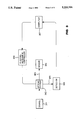
- FIG. 1 is a block diagram showing a gas measuring system which incorporates either the first or second embodiments of the gas sensor made in accordance with the present invention.
- FIG. 2 is a sectional view of the first and second embodiments of the present invention.
- FIG. 3 is a block diagram showing a gas measuring system which incorporates either the third or fourth embodiments of the gas sensor made in accordance with the present invention.
- FIG. 4 is a sectional view of the sensor depicted in FIG. 3.
- FIG. 5 is another embodiment of the present invention.
- FIG. 1 is a block diagram showing the first and second embodiments of the gas sensor made in accordance with the present invention and incorporated into a gas measurement system.
- An operator selects the gas of interest through a computer 107 which then picks a filter in an optical system 102 through an electromechanical controller 108.
- the filter in the optical system 102 passes one or more selected wavelengths of the optical radiation from the multiple wavelengths emitted by a source 101.
- the source 101 is preferably a halogen lamp GE787, made by General Electric.
- the optical system 102 focuses the selected optical radiation into an input optical fiber 103 that is a commercial grade gradient index or step index optical fiber.
- the selected wavelengths are from a group which includes wavelengths of about 1.6 ⁇ m and from a range between 1.9 and 2.05 ⁇ m.
- the wavelength of the selected radiation is about 450 nm (nanometer).
- the input fiber 103 guides the radiation to a sensor 104 that is in a test medium which contains an unknown level of the gas of interest, namely CO 2 or O 2 .
- An output optical fiber 105 being the same material as the input optical fibers 103, connects to the output of the sensor. For the selected radiation, the optical fiber 103 and 105 have greater than 90% spectral transmission.
- the fiber is impermeable to the selected gas (and is malleable).
- the output fiber 105 directs the radiation which passes through the sensor 104 to a detector 106.
- the detector is preferably an ETX 300-GR22, manufactured by Epitaxx at Princeton N.J.
- the detector 106 measures the intensity of the passed-through radiation and the computer 107 which receives the output from the detector 106 operates to produce a measurement of the level of selected gas in the test medium.
- FIG. 2 depicts a sectional view of the sensor 104 shown in FIG. 1.
- the sensor 104 is made from a step index optical fiber, such as a PCS Anhydroguide Vis IR Fiber by Fiberguide Industries, with the buffer and cladding removed exposing the core of the fiber.
- a step index optical fiber such as a PCS Anhydroguide Vis IR Fiber by Fiberguide Industries
- One preferred material for the fiber core 210 is fused silica with a refractive index of 1.46.
- the sensor 104 has a gas-enriching polymer 211 coaxially mounted to the fiber core 210.
- the thickness of the gas enriching polymer 211 is determined by the response time needed.
- the diameter of the fiber core 210 is determined by such considerations as the signal variation needed, the source brightness, and the ease of fabrication of the sensor 104. In first and second working embodiments of the present invention, a fiber with a core diameter of 800 ⁇ m was used to make fabrication relatively simple. However, an optimal diameter is believed to be in the range between 50 and 100 ⁇ m.
- the gas-enriching polymer 211 selected for the first and second embodiments of the present invention has a high diffusion coefficient for gases such as O 2 and CO 2 .
- the diffusion coefficient of a gas in a polymer measures the diffusion speed of the gas.
- High diffusion coefficient implies quick equilibrium between the gas in the polymer and the test medium. The quicker a sensor equilibrates with the gas in the test medium, the quicker the sensor can respond to changes in the concentration of the gases in the test medium.
- a high diffusion coefficient sensor means a sensor with a fast response time. This is essential for some patient monitoring applications.
- the selected gas enriching polymer also has high solubility for gases such as O 2 and CO 2 .
- the solubility of a gas in a polymer is the concentration of gas in the polymer compared to the concentration of gas in air having the same volume as the polymer and under standard temperature and pressure.
- High solubility is synonymous to high enrichment factor that is one main element of a high sensitivity sensor.
- the refractive index of the gas-enriching polymer 211 is preferably very close to the refractive index of the core of the step index optical fiber in the optical radiation with the selected wavelengths. This results in significant amounts of the radiation in the step index optical fiber being propagated into the gas-enriching polymer and reacting with the gas in the polymer.
- the reduction in intensity of the optical radiation absorbed by the CO 2 is a measure of the concentration of CO 2 in the test medium.
- Carbon dioxide strongly absorbs the radiation with a wavelength of 4.26 ⁇ m and weakly absorbs the radiation having wavelengths from 1.9 to 2.05 ⁇ m and 1.6 ⁇ m in the measuring medium.
- compensation for the reduction in absorption is via the enrichment factor of the polymer 211. Since the CO 2 concentration in the polymer 211 is higher than in the test medium, the reduction in absorption is compensated by the increase in concentration.
- the length of a working first embodiment of the sensor is 8 cm and the optimal length of the sensor is believed to be about 50 cm.
- the second embodiment of the present invention measures O 2 .
- the detection of O 2 is based on the phenomenon of fluorescence quenching using a dye dissolved in the polymer.
- a preferred dye is tris(4,7-diphenyl-1,10 phenanthroline) ruthenium II dichloride.
- Tables 1 and 2 show some examples and properties of materials suitable for the measuring medium 211, with the enriching factor being designated as ENR FAC.
- One preferred measuring medium 211 is a polymer known as poly(trimethylsilylpropyne).
- the solubility of CO 2 in this material is about 11.6 cubic centimeter (cc) per cc of the polymer at 25° C. and one atmospheric pressure. This means that the concentration of CO 2 is 11.6 times higher in the polymer than in the same volume of air at same temperature and pressure.
- the solubility of CO 2 is about 7.7 and O 2 in this polymer is about 5.14.
- the solubility of O 2 is not as essential because O 2 significantly quenches the radiation emitted by the dye.
- CO 2 does not absorb as well for radiation around 1.9 to 2.05 ⁇ m and 1.6 ⁇ m so a higher concentration of CO 2 for reaction with the radiation is needed.
- the diffusion coefficient of O 2 and CO 2 in the polymer 211 is in the order of 10 -5 cm 2 /second which is about three to five orders of magnitude higher than most other polymers.
- the refractive index of the polymer is about 1.46. It is almost the same as the fiber core.
- the length of a working second embodiment of the sensor is 8 cm and the optimal length of the sensor is about 50 cm.
- a reflecting membrane 212 coats the gas enriching polymer 211.
- the refractive index of the reflecting membrane 212 is lower than the refractive index of the polymer and the fiber core.
- This reflecting membrane 212 is very permeable to the selected gas but the membrane bounces the optical radiation preferably through total internal reflection back into the polymer 211.
- One example of the reflecting membrane 212 is DuPont "TEFLON AF" with a refractive index of 1.23.
- the compound "TEFLON AF" is made of 1,3-dioxole, 4,5-difluoro-2,2-bis (trifluoromehtyl)-,polymer with tetrafluoroethene.
- Another type of reflecting membrane is porous gold.
- the trade-off regarding the thickness of the reflecting membrane 212 is the amount of reflection to the permeability of the gas. An extremely thin layer of gold or a highly porous gold will be very permeable to the gas but does not give sufficient reflection to the radiation.
- test medium does not affect the surface property of the measuring medium 211 of the sensor when the reflecting membrane 212 is removed, that reflecting membrane may not be needed. In other words, because air or vacuum has a refractive index of 1.00 that is significantly less than that of the gas-enriching polymer 211, any of the radiation in the sensor is captured within the polymer and the core of the fiber. If the test medium affects the surface property of the measuring medium 211, the reflecting membrane 212 supplies a controlled environment for the sensor 104.
- the gas-enriching polymer 211 and the reflecting membrane 212 are very thin to minimize the diffusion time of the selected gas and the response time of the sensor 104. In addition, the sensor is relatively more malleable if the layers are thin.
- the polymer 211 has to have enough volume to give sufficient detectable signal and the reflecting membrane 212 has to be thick enough to trap the radiation in the polymer. To give sufficient volume for the polymer 211, one can either have a thick polymer or a long sensing path. Since a thick polymer 211 would decrease the response time of the sensor, the preferred arrangement is a sensing path with sufficient length. The length required depends on the signal to noise ratio of the gas measurement system. The detected signal should be preferably more than twice the noise level of the gas measuring system.
- Typical thickness for the polymer 211, poly(trimethylsilylpropyne) is from 10 to 50 ⁇ m and the preferred thickness is 10 ⁇ m.
- Typical thickness for the "TEFLON AF" reflecting membrane 212 is about 5 microns.
- FIG. 3 is a block diagram showing the gas measuring system which incorporates either the third or fourth embodiments of the gas sensor made in accordance with the present invention.
- An operator selects the gas of interest through a computer 307 which then picks a filter in an optical system 302 through an electromechanical controller 308.
- the filter passes one or more wavelengths of the optical radiation from the multiple wavelengths emitted by a source 301.
- the optical system 302 focuses the radiation through an input fiber 303 to a sensor 304.
- the sensor 304 as will be described below, reflects the radiation passing through the sensor back to the optical fiber 303 and towards the optical system 302.
- the optical system 302 couples the reflected radiation to an output fiber 305 that transmits such radiation to a detector 306.
- the detector 306 measures the intensity of the reflected radiation and the computer 307 which receives the output from the detector 306 operates to produce a measurement of the level of selected gas in the test medium.
- FIG. 4 depicts a sectional view of the sensor 304.
- the third embodiment of the sensor in the present invention measures the concentration of CO 2 with the same measuring medium as in the first embodiment.
- the fourth embodiment of the present invention measures the concentration of O 2 with the same measuring medium as in the second embodiment.
- the third embodiment thus does not include a dye which is included in the measuring medium of the fourth embodiment.
- the sensor 304 as used in the third and fourth embodiments has a measuring medium 411 and a distal-end reflecting membrane 412 at the end of an optical fiber 410.
- the fiber 410 is cut at the distal-end to expose its core.
- the fiber can be either a gradient index optical fiber or a step index optical fiber.
- the measuring medium 411 with a distal-end reflecting membrane 412 are then coaxially abutted to the core.
- a reflecting membrane 413 fastens the fiber 410 and the polymer 411 with the distal-end reflecting membrane 412 together.
- the reflecting membrane 413 is preferably made of the same material as the reflecting membrane in the first and second embodiments of the present invention or can be made of silicone rubber.
- the measuring medium 411 is preferably made of the same material as the measuring medium of the first and the second embodiments of the present invention.
- the distal-end reflecting membrane 412 is designed to be highly reflective, which would be the case if it was made of metal, in order to return any of the radiation which may be incident perpendicularly onto the distal-end reflecting membrane.
- a sensor through combining the first and second or the third and fourth embodiments will detect two different selected gases, such as O 2 and CO 2 . Since both gases are in the same gas enriching polymer, the dye selected is chosen so that it does not react with the radiation used to detect CO 2 . Similarly, CO 2 should not quench the fluorescence of the dye, nor should it react with the radiation used to detect O 2 . Furthermore, O 2 should not react with the wavelengths of any radiation that cause the fluorescence of the dye nor react with the wavelengths of any radiation used to detect CO 2 .
- the sensor fabricated through combining the first and the third embodiments will have a relatively high volume of measuring medium. With this high volume of enriching polymer, the sensor will capture more gas leading to a more sensitive sensor than prior art sensors.
- the gas enriching polymer is coaxially mounted around the core and at the end of the optical fiber.
- the first, second and third embodiments when combined also results in a sensor with a relatively high volume of enriching polymer for measuring two selected gases.
- a sensor with a relatively high volume of enriching polymer for measuring two selected gases.
- FIG. 5 shows another configuration of the present invention made with a long sensing path. It is desirable to have a high volume of measuring medium because increasing the volume increases the sensitivity of the sensor. One way to achieve high volume is by making the measuring medium thicker. However, a thick polymer adversely affects the response time of the sensor because more time is needed for the selected gas to diffuse into the gas-enriching polymer. A preferred method to increase the volume without increasing the response time is by making the sensing path longer.
- FIG. 5 shows a preferred embodiment having a long sensing path within a small area by coiling the sensing path. This configuration is feasible because the present invention is malleable.
- the present invention can be made to be small enough for mounting near the end of a fiber optic cable and for insertion into the throat of a patient, including a neonate, without intubation.
- the preferred embodiments of the present invention use optical radiation for the detection of only CO 2 and O 2
- other wavelengths of radiation may be used for those applications where it is desirable to detect other fluids by measuring absorption spectra in other regions, such as but not limited to the ultraviolet, infrared or microwave wavelengths.
Abstract
Description
              TABLE 1
______________________________________
                           ENR FAC
POLYMER                    at 35° C.
______________________________________
Poly(trimethylsilyl-propyne)
                           7.7
2,6-dimethyl-1,4 poly(phenylene oxide)
                           6.6
Polyimide from 3,3',4,4'-bisphenyltetracarboxylic
                           15.3
di-anhydride (BPDA) and 4,4'-diaminodiphenylsul-
fone
Polyimide from phenylmaleiimide dianhydride
                           11.6
(PMDA) and 4,4'-oxydianiline (ODA)
Polyimide from BPDA and ODA
                           8.9
Polyimide from 1,2,4-tricarboxy-3-
                           16.0
carboxymethylcyclopentane dianhydride and 4 4'-
oxydianiline (ODA)
Poly(phenolphthalein phthalate)
                           11.3
Tetrabromo-polycarbonate   7.8
Tetrachloro-polycarbonate  7.2
Tetramethyl-polycarbonate  7.1
Polysulfone                6.1
Polyetherimide             6.0
Polyarylate                5.5
Polycarbonate              4.6
Polystyrene                1.8
______________________________________
              TABLE 2
______________________________________
Properties of Poly(trimethylsilyl-propyne)
GAS  TEMP °C.
               ENR FAC   DIFFUSION COEFFICIENT
______________________________________
CO.sub.2
     35        7.7       2.63 * 10.sup.-5
O.sub.2
     35         5.14     3.96 * 10.sup.-5
______________________________________
Claims (24)
Priority Applications (3)
| Application Number | Priority Date | Filing Date | Title |
|---|---|---|---|
| US07/816,987 US5233194A (en) | 1992-01-03 | 1992-01-03 | Optical gas sensor with enriching polymer |
| JP4348696A JPH05249036A (en) | 1992-01-03 | 1992-12-28 | Gas measuring apparatus |
| EP93300003A EP0550424A2 (en) | 1992-01-03 | 1993-01-04 | Optical gas sensor with enriching polymer |
Applications Claiming Priority (1)
| Application Number | Priority Date | Filing Date | Title |
|---|---|---|---|
| US07/816,987 US5233194A (en) | 1992-01-03 | 1992-01-03 | Optical gas sensor with enriching polymer |
Publications (1)
| Publication Number | Publication Date |
|---|---|
| US5233194A true US5233194A (en) | 1993-08-03 |
Family
ID=25222105
Family Applications (1)
| Application Number | Title | Priority Date | Filing Date |
|---|---|---|---|
| US07/816,987 Expired - Lifetime US5233194A (en) | 1992-01-03 | 1992-01-03 | Optical gas sensor with enriching polymer |
Country Status (3)
| Country | Link |
|---|---|
| US (1) | US5233194A (en) |
| EP (1) | EP0550424A2 (en) |
| JP (1) | JPH05249036A (en) |
Cited By (17)
| Publication number | Priority date | Publication date | Assignee | Title |
|---|---|---|---|---|
| US5708957A (en) * | 1996-02-02 | 1998-01-13 | University Of Iowa Research Foundation | Optical sensor with radioluminescent light source |
| US5854863A (en) * | 1996-03-15 | 1998-12-29 | Erb; Judith | Surface treatment and light injection method and apparatus |
| US5931161A (en) * | 1998-03-18 | 1999-08-03 | Datex-Ohmeda, Inc. | On-airway respiratory gas monitor employing transformed infrared signals |
| WO1999056109A1 (en) * | 1998-04-27 | 1999-11-04 | Gottlieb Amos J | Article and method for optical and spectroscopic measurement of a dissolved gas |
| US6325978B1 (en) | 1998-08-04 | 2001-12-04 | Ntc Technology Inc. | Oxygen monitoring and apparatus |
| US6383815B1 (en) | 2001-04-04 | 2002-05-07 | General Electric Company | Devices and methods for measurements of barrier properties of coating arrays |
| US20020172620A1 (en) * | 2001-04-04 | 2002-11-21 | Potyrailo Radislav Alexandrovich | Systems and methods for rapid evaluation of chemical resistance of materials |
| US6567753B2 (en) | 2001-04-04 | 2003-05-20 | General Electric Company | Devices and methods for simultaneous measurement of transmission of vapors through a plurality of sheet materials |
| US6629934B2 (en) | 2000-02-02 | 2003-10-07 | Healthetech, Inc. | Indirect calorimeter for medical applications |
| US6686201B2 (en) | 2001-04-04 | 2004-02-03 | General Electric Company | Chemically-resistant sensor devices, and systems and methods for using same |
| US20040191122A1 (en) * | 2000-03-06 | 2004-09-30 | Potyrailo Radislav Alexandrovich | Method and apparatus for rapid screening of volatiles |
| US6815211B1 (en) | 1998-08-04 | 2004-11-09 | Ntc Technology | Oxygen monitoring methods and apparatus (I) |
| US20080094624A1 (en) * | 2006-10-19 | 2008-04-24 | Sporian Microsystems, Inc. | Optical sensor with biologically reactive surface |
| US20080094632A1 (en) * | 2006-10-19 | 2008-04-24 | Sporian Microsystems, Inc. | Optical Sensor With Chemically Reactive Surface |
| US20120214249A1 (en) * | 2011-02-17 | 2012-08-23 | Robert Francis Belongia | Optical gas sensor for use with electrical equipment and methods of assembling same |
| CN108072620A (en) * | 2018-02-05 | 2018-05-25 | 西南石油大学 | It is a kind of using optical fiber evanescent field sensor research dyestuff solid-liquid interface adsorption dynamics adsorption kinetics method |
| CN110811637A (en) * | 2013-07-22 | 2020-02-21 | 申特克股份公司 | Sensor for detecting gas and method for detecting gas |
Families Citing this family (6)
| Publication number | Priority date | Publication date | Assignee | Title |
|---|---|---|---|---|
| SE9503139L (en) * | 1995-09-11 | 1997-03-12 | Minco Ab | Device for measuring the CO2 concentration in a gas |
| JPH11242143A (en) * | 1998-02-25 | 1999-09-07 | Hitachi Ltd | Optical fiber and optical sensing system using the optical fiber |
| AT407090B (en) * | 1998-09-15 | 2000-12-27 | Joanneum Research Forschungsge | OPTO-CHEMICAL SENSOR AND METHOD FOR THE PRODUCTION THEREOF |
| AT512498B1 (en) | 2012-06-06 | 2013-09-15 | Joanneum Res Forschungsgmbh | Opto-chemical sensor |
| CN109164049B (en) * | 2018-07-24 | 2020-09-22 | 重庆理工大学 | Manufacturing method of CO sensor, sensor and detection method of CO concentration |
| US11193916B2 (en) * | 2019-05-02 | 2021-12-07 | SciLogica Corp. | Calibration of a gas sensor |
Citations (6)
| Publication number | Priority date | Publication date | Assignee | Title |
|---|---|---|---|---|
| US4201222A (en) * | 1977-08-31 | 1980-05-06 | Thomas Haase | Method and apparatus for in vivo measurement of blood gas partial pressures, blood pressure and blood pulse |
| EP0144713A2 (en) * | 1983-12-06 | 1985-06-19 | Max-Planck-Gesellschaft zur Förderung der Wissenschaften e.V. | Device for optically measuring concentration of substances |
| EP0259951A2 (en) * | 1986-09-08 | 1988-03-16 | C.R. Bard, Inc. | Luminescent oxygen sensor based on a lanthanide complex |
| US4785814A (en) * | 1987-08-11 | 1988-11-22 | Cordis Corporation | Optical probe for measuring pH and oxygen in blood and employing a composite membrane |
| US4800886A (en) * | 1986-07-14 | 1989-01-31 | C. R. Bard, Inc. | Sensor for measuring the concentration of a gaseous component in a fluid by absorption |
| US5142155A (en) * | 1991-03-11 | 1992-08-25 | Hewlett-Packard Company | Catheter tip fluorescence-quenching fiber optic pressure sensor |
Family Cites Families (4)
| Publication number | Priority date | Publication date | Assignee | Title |
|---|---|---|---|---|
| CA1261717A (en) * | 1982-12-23 | 1989-09-26 | John R. Bacon | Method and apparatus for oxygen determination |
| EP0190830A3 (en) * | 1985-02-04 | 1988-04-27 | Gould Inc. | Single optical fiber sensor for measuring the partial pressure of oxygen |
| US4805623A (en) * | 1987-09-04 | 1989-02-21 | Vander Corporation | Spectrophotometric method for quantitatively determining the concentration of a dilute component in a light- or other radiation-scattering environment |
| US5176882A (en) * | 1990-12-06 | 1993-01-05 | Hewlett-Packard Company | Dual fiberoptic cell for multiple serum measurements |
-
1992
- 1992-01-03 US US07/816,987 patent/US5233194A/en not_active Expired - Lifetime
- 1992-12-28 JP JP4348696A patent/JPH05249036A/en active Pending
-
1993
- 1993-01-04 EP EP93300003A patent/EP0550424A2/en not_active Ceased
Patent Citations (6)
| Publication number | Priority date | Publication date | Assignee | Title |
|---|---|---|---|---|
| US4201222A (en) * | 1977-08-31 | 1980-05-06 | Thomas Haase | Method and apparatus for in vivo measurement of blood gas partial pressures, blood pressure and blood pulse |
| EP0144713A2 (en) * | 1983-12-06 | 1985-06-19 | Max-Planck-Gesellschaft zur Förderung der Wissenschaften e.V. | Device for optically measuring concentration of substances |
| US4800886A (en) * | 1986-07-14 | 1989-01-31 | C. R. Bard, Inc. | Sensor for measuring the concentration of a gaseous component in a fluid by absorption |
| EP0259951A2 (en) * | 1986-09-08 | 1988-03-16 | C.R. Bard, Inc. | Luminescent oxygen sensor based on a lanthanide complex |
| US4785814A (en) * | 1987-08-11 | 1988-11-22 | Cordis Corporation | Optical probe for measuring pH and oxygen in blood and employing a composite membrane |
| US5142155A (en) * | 1991-03-11 | 1992-08-25 | Hewlett-Packard Company | Catheter tip fluorescence-quenching fiber optic pressure sensor |
Cited By (24)
| Publication number | Priority date | Publication date | Assignee | Title |
|---|---|---|---|---|
| US5708957A (en) * | 1996-02-02 | 1998-01-13 | University Of Iowa Research Foundation | Optical sensor with radioluminescent light source |
| US5854863A (en) * | 1996-03-15 | 1998-12-29 | Erb; Judith | Surface treatment and light injection method and apparatus |
| US5931161A (en) * | 1998-03-18 | 1999-08-03 | Datex-Ohmeda, Inc. | On-airway respiratory gas monitor employing transformed infrared signals |
| WO1999056109A1 (en) * | 1998-04-27 | 1999-11-04 | Gottlieb Amos J | Article and method for optical and spectroscopic measurement of a dissolved gas |
| US7897109B2 (en) | 1998-08-04 | 2011-03-01 | Ric Investments, Llc | Oxygen monitoring apparatus |
| US6325978B1 (en) | 1998-08-04 | 2001-12-04 | Ntc Technology Inc. | Oxygen monitoring and apparatus |
| US6815211B1 (en) | 1998-08-04 | 2004-11-09 | Ntc Technology | Oxygen monitoring methods and apparatus (I) |
| US6616896B2 (en) | 1998-08-04 | 2003-09-09 | Ntc Technology Inc. | Oxygen monitoring apparatus |
| US6629934B2 (en) | 2000-02-02 | 2003-10-07 | Healthetech, Inc. | Indirect calorimeter for medical applications |
| US6881585B1 (en) * | 2000-03-06 | 2005-04-19 | General Electric Company | Method and apparatus for rapid screening of volatiles |
| US20040191122A1 (en) * | 2000-03-06 | 2004-09-30 | Potyrailo Radislav Alexandrovich | Method and apparatus for rapid screening of volatiles |
| US6686201B2 (en) | 2001-04-04 | 2004-02-03 | General Electric Company | Chemically-resistant sensor devices, and systems and methods for using same |
| US6567753B2 (en) | 2001-04-04 | 2003-05-20 | General Electric Company | Devices and methods for simultaneous measurement of transmission of vapors through a plurality of sheet materials |
| US6383815B1 (en) | 2001-04-04 | 2002-05-07 | General Electric Company | Devices and methods for measurements of barrier properties of coating arrays |
| US20020172620A1 (en) * | 2001-04-04 | 2002-11-21 | Potyrailo Radislav Alexandrovich | Systems and methods for rapid evaluation of chemical resistance of materials |
| US7602496B2 (en) | 2006-10-19 | 2009-10-13 | Sporian Microsystems, Inc. | Optical sensor with biologically reactive surface |
| US20080094632A1 (en) * | 2006-10-19 | 2008-04-24 | Sporian Microsystems, Inc. | Optical Sensor With Chemically Reactive Surface |
| US7652767B2 (en) | 2006-10-19 | 2010-01-26 | Sporian Microsystems, Inc. | Optical sensor with chemically reactive surface |
| US20080094624A1 (en) * | 2006-10-19 | 2008-04-24 | Sporian Microsystems, Inc. | Optical sensor with biologically reactive surface |
| US20120214249A1 (en) * | 2011-02-17 | 2012-08-23 | Robert Francis Belongia | Optical gas sensor for use with electrical equipment and methods of assembling same |
| US8889422B2 (en) * | 2011-02-17 | 2014-11-18 | General Electric Company | Optical gas sensor for use with electrical equipment and methods of assembling same |
| CN110811637A (en) * | 2013-07-22 | 2020-02-21 | 申特克股份公司 | Sensor for detecting gas and method for detecting gas |
| CN110811637B (en) * | 2013-07-22 | 2023-02-21 | 申特克股份公司 | Sensor for detecting gas and method for detecting gas |
| CN108072620A (en) * | 2018-02-05 | 2018-05-25 | 西南石油大学 | It is a kind of using optical fiber evanescent field sensor research dyestuff solid-liquid interface adsorption dynamics adsorption kinetics method |
Also Published As
| Publication number | Publication date |
|---|---|
| EP0550424A2 (en) | 1993-07-07 |
| JPH05249036A (en) | 1993-09-28 |
| EP0550424A3 (en) | 1994-05-04 |
Similar Documents
| Publication | Publication Date | Title |
|---|---|---|
| US5233194A (en) | Optical gas sensor with enriching polymer | |
| US4894532A (en) | Optical fiber sensor with light absorbing moisture-sensitive coating | |
| US5119463A (en) | Compound optical probe employing single optical waveguide | |
| Lieberman et al. | A distributed fiber optic sensor based on cladding fluorescence | |
| US5098659A (en) | Apparatus for continuously monitoring a plurality of chemical analytes through a single optical fiber and method of making | |
| Klein et al. | Integrated-optic ammonia sensor | |
| AU2007303310B8 (en) | Formaldehyde detector body, formaldehyde detector, formaldehyde detection method and formaldehyde detection reagent | |
| US6818895B2 (en) | Respiratory gas analyzer | |
| Mac Craith et al. | Fibre optic chemical sensors based on evanescent wave interactions in sol-gel-derived porous coatings: Code: F7 | |
| TWI424155B (en) | Surface plasmon resonance sensor | |
| JP2807777B2 (en) | Optical absorption spectrum measuring device using slab optical waveguide | |
| Eguchi | Optical gas sensors | |
| EP0536978A1 (en) | Humidity sensors | |
| Dakin | Review of fibre optic gas sensors | |
| Klein et al. | Integrated-optic ammonia sensor | |
| MacCraith | Optical fiber chemical sensor systems and devices | |
| Narayanaswamy | Optical fibre sensors for gaseous chemical species | |
| Kieslinger et al. | Capillary waveguide optrodes for medical applications | |
| Walt | Continuous clinical monitoring using fiber optic sensors | |
| O'KELLY et al. | BD MAC CRAITH, C. MCDONAGH, G. O'KEEFFE AND T. BUTLER | |
| JPS5992332A (en) | Moisture detector | |
| EP4302079A1 (en) | Fibre optic chemical sensing | |
| Stepanov et al. | Multicomponent gas analyzers based on tunable diode lasers | |
| Mendoza et al. | Sol-gel-based fiber optic and integrated optic chemical sensors for environmental monitoring and process control | |
| IE910636A1 (en) | Method and apparatus for optical waveguide sensing using an¹environmentally-sensitive dye in sol-gel glass |
Legal Events
| Date | Code | Title | Description |
|---|---|---|---|
| AS | Assignment |
Owner name: HEWLETT-PACKARD COMPANY, CALIFORNIA Free format text: ASSIGNMENT OF ASSIGNORS INTEREST.;ASSIGNORS:MAUZE, GANAPATI R.;GRAY, DAMIEN F.;REEL/FRAME:006215/0292 Effective date: 19911217 |
|
| STCF | Information on status: patent grant |
Free format text: PATENTED CASE |
|
| FEPP | Fee payment procedure |
Free format text: PAYOR NUMBER ASSIGNED (ORIGINAL EVENT CODE: ASPN); ENTITY STATUS OF PATENT OWNER: LARGE ENTITY |
|
| FEPP | Fee payment procedure |
Free format text: PAYER NUMBER DE-ASSIGNED (ORIGINAL EVENT CODE: RMPN); ENTITY STATUS OF PATENT OWNER: LARGE ENTITY Free format text: PAYOR NUMBER ASSIGNED (ORIGINAL EVENT CODE: ASPN); ENTITY STATUS OF PATENT OWNER: LARGE ENTITY |
|
| FPAY | Fee payment |
Year of fee payment: 4 |
|
| AS | Assignment |
Owner name: HEWLETT-PACKARD COMPANY, A DELAWARE CORPORATION, C Free format text: MERGER;ASSIGNOR:HEWLETT-PACKARD COMPANY, A CALIFORNIA CORPORATION;REEL/FRAME:010841/0649 Effective date: 19980520 |
|
| AS | Assignment |
Owner name: AGILENT TECHNOLOGIES INC., CALIFORNIA Free format text: ASSIGNMENT OF ASSIGNORS INTEREST;ASSIGNOR:HEWLETT-PACKARD COMPANY, A DELAWARE CORPORATION;REEL/FRAME:010901/0336 Effective date: 20000520 |
|
| FPAY | Fee payment |
Year of fee payment: 8 |
|
| REMI | Maintenance fee reminder mailed | ||
| FPAY | Fee payment |
Year of fee payment: 12 |
|
| SULP | Surcharge for late payment |
Year of fee payment: 11 |
|
| AS | Assignment |
Owner name: PELIKAN TECHNOLOGIES, INC., CALIFORNIA Free format text: ASSIGNMENT OF ASSIGNORS INTEREST;ASSIGNOR:AGILENT TECHNOLOGIES, INC.;REEL/FRAME:022214/0209 Effective date: 20090206 |