US5226840A - Electrical connector terminal and contact - Google Patents
Electrical connector terminal and contact Download PDFInfo
- Publication number
- US5226840A US5226840A US07/706,470 US70647091A US5226840A US 5226840 A US5226840 A US 5226840A US 70647091 A US70647091 A US 70647091A US 5226840 A US5226840 A US 5226840A
- Authority
- US
- United States
- Prior art keywords
- forming
- terminal
- folded
- thickness
- face
- Prior art date
- Legal status (The legal status is an assumption and is not a legal conclusion. Google has not performed a legal analysis and makes no representation as to the accuracy of the status listed.)
- Expired - Lifetime
Links
Images

Classifications
-
- H—ELECTRICITY
- H01—ELECTRIC ELEMENTS
- H01H—ELECTRIC SWITCHES; RELAYS; SELECTORS; EMERGENCY PROTECTIVE DEVICES
- H01H23/00—Tumbler or rocker switches, i.e. switches characterised by being operated by rocking an operating member in the form of a rocker button
- H01H23/02—Details
- H01H23/08—Bases; Stationary contacts mounted thereon
-
- H—ELECTRICITY
- H01—ELECTRIC ELEMENTS
- H01R—ELECTRICALLY-CONDUCTIVE CONNECTIONS; STRUCTURAL ASSOCIATIONS OF A PLURALITY OF MUTUALLY-INSULATED ELECTRICAL CONNECTING ELEMENTS; COUPLING DEVICES; CURRENT COLLECTORS
- H01R13/00—Details of coupling devices of the kinds covered by groups H01R12/70 or H01R24/00 - H01R33/00
- H01R13/02—Contact members
- H01R13/04—Pins or blades for co-operation with sockets
-
- H—ELECTRICITY
- H01—ELECTRIC ELEMENTS
- H01R—ELECTRICALLY-CONDUCTIVE CONNECTIONS; STRUCTURAL ASSOCIATIONS OF A PLURALITY OF MUTUALLY-INSULATED ELECTRICAL CONNECTING ELEMENTS; COUPLING DEVICES; CURRENT COLLECTORS
- H01R43/00—Apparatus or processes specially adapted for manufacturing, assembling, maintaining, or repairing of line connectors or current collectors or for joining electric conductors
- H01R43/16—Apparatus or processes specially adapted for manufacturing, assembling, maintaining, or repairing of line connectors or current collectors or for joining electric conductors for manufacturing contact members, e.g. by punching and by bending
-
- H—ELECTRICITY
- H01—ELECTRIC ELEMENTS
- H01H—ELECTRIC SWITCHES; RELAYS; SELECTORS; EMERGENCY PROTECTIVE DEVICES
- H01H11/00—Apparatus or processes specially adapted for the manufacture of electric switches
- H01H11/04—Apparatus or processes specially adapted for the manufacture of electric switches of switch contacts
-
- H—ELECTRICITY
- H01—ELECTRIC ELEMENTS
- H01R—ELECTRICALLY-CONDUCTIVE CONNECTIONS; STRUCTURAL ASSOCIATIONS OF A PLURALITY OF MUTUALLY-INSULATED ELECTRICAL CONNECTING ELEMENTS; COUPLING DEVICES; CURRENT COLLECTORS
- H01R13/00—Details of coupling devices of the kinds covered by groups H01R12/70 or H01R24/00 - H01R33/00
- H01R13/40—Securing contact members in or to a base or case; Insulating of contact members
- H01R13/405—Securing in non-demountable manner, e.g. moulding, riveting
- H01R13/41—Securing in non-demountable manner, e.g. moulding, riveting by frictional grip in grommet, panel or base
-
- Y—GENERAL TAGGING OF NEW TECHNOLOGICAL DEVELOPMENTS; GENERAL TAGGING OF CROSS-SECTIONAL TECHNOLOGIES SPANNING OVER SEVERAL SECTIONS OF THE IPC; TECHNICAL SUBJECTS COVERED BY FORMER USPC CROSS-REFERENCE ART COLLECTIONS [XRACs] AND DIGESTS
- Y10—TECHNICAL SUBJECTS COVERED BY FORMER USPC
- Y10T—TECHNICAL SUBJECTS COVERED BY FORMER US CLASSIFICATION
- Y10T29/00—Metal working
- Y10T29/49—Method of mechanical manufacture
- Y10T29/49002—Electrical device making
- Y10T29/49117—Conductor or circuit manufacturing
- Y10T29/49204—Contact or terminal manufacturing
- Y10T29/49208—Contact or terminal manufacturing by assembling plural parts
- Y10T29/49222—Contact or terminal manufacturing by assembling plural parts forming array of contacts or terminals
Definitions
- the present invention provides a unique and novel spade-type or flat electrical connector and terminal pin which also serves as an electrical switch contact.
- the connector terminal pin of the present invention is formed by stamping a "T"-shaped blank from flat sheet stock, then folding the opposite arms of the "T"-shaped blank in accordion fashion to a closed stacked arrangement to form the head portion of the connector terminal pin.
- Barbs are formed on the trunk of the "T"-shaped blank which enables the connector terminal pin to be pressed into a switch base; and, the barbs thereupon prevent removal of the installed connector pin.
- Switch blade fulcrum surfaces are formed in the edges of the accordion-folded head and other portions of the edges adjacent the fulcrum surfaces are adapted serve as electrical switching contacts.
- the present invention thus provides a low-cost one-piece connector terminal pin having a flat spade-type configuration which may be formed from sheet stock and which provides a low cost alternative to cold headed and swaged pins.
- FIG. 1 is an axonometric view of the "T"-shaped blank stamped from sheet stock
- FIG. 2 is an axonometric view of the completed terminal pin formed from the blank of FIG. 1;
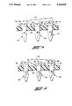
- FIG. 3 is a cross-sectional view of a switch base having a plurality of the pins of FIG. 2 mounted thereon;
- FIG. 4 is a view similar to FIG. 3.
- a flat blank from which the terminal is formed is indicated generally at 10 in the condition as it appears after stamping from sheet stock of a desired thickness indicated by the reference character "t".
- the blank 10 has a pair of oppositely directed arm portions 12,14 and a terminal or spade-like trunk portion denoted by reference numeral 16 extending at right angles from arms 12,14.
- the terminal portion 16 has a tapered portion 18 formed at the free end thereof to facilitate bayonet-type connection thereto as, for example, with a wiring harness connector (not shown).
- the terminal portion 16 has preferably a plurality of barbs 20,22 formed on opposite sides thereof adjacent the arms 12,14 to facilitate installation of the terminal 16 in a switch base as will hereinafter be described.
- the blank 10 is formed of metal sheet stock having suitable electrical and corrosion-resistant properties such as, for example, brass material or any other material suitable for the application environment in which the terminal is to be employed.
- the formed connector terminal is illustrated generally at 30 as having the arms 12,14 folded accordion-style in closed-stack serpentine arrangement to a convenient width indicated by reference character "w" to thereby form a head portion indicated generally at 32 and which is comprised of multiple thicknesses "t" of the material depending upon the number of folds in the arms 12,14.
- each of the arms 12,14 is folded back upon itself twice to give a thickness to the head portion 32 of five times the thickness "t". It will be understood that the folding may be accomplished in a single stage operation and thus renders the terminal 30 efficient to manufacture.
- the fulcrumming surface in the form of a V-shaped notch 34 is formed in the edges of the folded arms for use with associated switch components as will hereinafter be described.
- the remaining portions of the edges of the folded arms 12,14 adjacent the notch 34 are formed to a suitably flattened configuration to provide electrical switch contact surfaces.
- the completed terminal 30 as illustrated in FIG. 2 thus functions as a spade-type connector terminal with respect to portion 16 and the head portion 32 serves to register the terminal in a switch base structure by contact with the undersurface of the head portion 32.
- the notch 34 and adjacent edge surfaces of the folded arms 12,14 serve as electrical contact surfaces and fulcrumming surfaces for associated switch components.
- a plurality of the terminals 30 are show installed in a suitable switch base structure indicated by reference numeral 40, which may comprise any suitably configured insulating material for receiving the barbed portions of the terminal therein with the blade portion extending therethrough.
- a suitable switch base structure indicated by reference numeral 40 which may comprise any suitably configured insulating material for receiving the barbed portions of the terminal therein with the blade portion extending therethrough.
- three of the terminals 30 are disposed in aligned space relationship in the base structure 40 with the undersurface of head portion 32 of each terminal registered against the upper surface of the base structure 40 for accurate positioning.
- This arrangement enables a suitable pivoted switching member 42 indicated in dashed outline in FIGS. 3 and 4, to be fulcrummed in the notch 34 provided in the center of the three terminals 30.
- the switching member 42 may alternately pivot to make contact with the end terminals 30 to provide an electrical circuit between either of the end terminals and the center terminal.
- the flat portions of the terminal heads 32 indicated by reference numerals 38,36 act as switching contacts with the movable switch member 42 shown in dashed outline.
- the present invention thus provides a unique and novel low cost combination spade-type connector terminal and switching contact which is formed integrally from a "T"-shaped blank stamped from flat sheet stock.
- the combination connector terminal and switch contact of the present invention provides a low cost alternative to cold heading and swaging a terminal from round wire stock.
Abstract
Description
Claims (12)
Priority Applications (1)
| Application Number | Priority Date | Filing Date | Title |
|---|---|---|---|
| US07/706,470 US5226840A (en) | 1991-05-28 | 1991-05-28 | Electrical connector terminal and contact |
Applications Claiming Priority (1)
| Application Number | Priority Date | Filing Date | Title |
|---|---|---|---|
| US07/706,470 US5226840A (en) | 1991-05-28 | 1991-05-28 | Electrical connector terminal and contact |
Publications (1)
| Publication Number | Publication Date |
|---|---|
| US5226840A true US5226840A (en) | 1993-07-13 |
Family
ID=24837720
Family Applications (1)
| Application Number | Title | Priority Date | Filing Date |
|---|---|---|---|
| US07/706,470 Expired - Lifetime US5226840A (en) | 1991-05-28 | 1991-05-28 | Electrical connector terminal and contact |
Country Status (1)
| Country | Link |
|---|---|
| US (1) | US5226840A (en) |
Cited By (13)
| Publication number | Priority date | Publication date | Assignee | Title |
|---|---|---|---|---|
| US5522008A (en) * | 1994-03-16 | 1996-05-28 | Bernard; Costello J. | Device for heating and vaporizing a vaporizable module |
| US5885119A (en) * | 1995-05-27 | 1999-03-23 | Robert Bosch Gmbh | Multipole electrical plug connector |
| US5908336A (en) * | 1996-02-07 | 1999-06-01 | Robert Bosch Gmbh | Multipole electrical plug connector |
| US5970607A (en) * | 1993-09-30 | 1999-10-26 | Illinois Tool Works Inc. | Method of making an electrical subassembly |
| US5984735A (en) * | 1998-08-28 | 1999-11-16 | Lucent Technologies Inc. | Material displacement type retention mechanism for connector terminals |
| US6375478B1 (en) * | 1999-06-18 | 2002-04-23 | Nec Corporation | Connector well fit with printed circuit board |
| US20040102103A1 (en) * | 2001-06-19 | 2004-05-27 | Martin Kling | Electrical plug connector |
| US20050044704A1 (en) * | 2003-09-03 | 2005-03-03 | Ralph Jacques | Method for producing a crimp ear |
| US20090229113A1 (en) * | 2006-09-11 | 2009-09-17 | Apple Inc. | Actuator assembly |
| US20100035881A1 (en) * | 2005-09-22 | 2010-02-11 | Shiseido Company, Ltd. | Wrinkle-improving agent |
| US20110076861A1 (en) * | 2009-09-29 | 2011-03-31 | Flex-Cable | Laminar electrical connector |
| USD803785S1 (en) | 2016-02-19 | 2017-11-28 | Dinesh Wadhwani | Electric lamp socket |
| US10673164B2 (en) * | 2018-04-26 | 2020-06-02 | Hirose Electric Co., Ltd. | Electrical connector |
Citations (8)
| Publication number | Priority date | Publication date | Assignee | Title |
|---|---|---|---|---|
| US3437772A (en) * | 1966-06-06 | 1969-04-08 | Cutler Hammer Inc | Contact structure for electrical switching device and method of assembly |
| US3609861A (en) * | 1969-10-21 | 1971-10-05 | Kollsman Instr Corp | Method of manufacturing rotary switch rotor contact members |
| US3727175A (en) * | 1970-03-20 | 1973-04-10 | Holzer Patent Ag | Fork-shaped contact spring to produce a separable electric connection |
| US3742432A (en) * | 1972-04-24 | 1973-06-26 | Amp Inc | Electrical terminal having folded blade and method of manufacturing same |
| US3915543A (en) * | 1971-09-02 | 1975-10-28 | Heyman Mfg Co | Polarized electric contact blades |
| US4118103A (en) * | 1977-09-15 | 1978-10-03 | Amp Incorporated | Double-ended connecting device |
| US4854041A (en) * | 1987-09-01 | 1989-08-08 | Nihon Kaiheiki Industrial Co., Ltd. | Method of manufacturing a switch base |
| US4927379A (en) * | 1987-08-20 | 1990-05-22 | Johnson Electric Industrial Manufactory, Limited | Electrical connector |
-
1991
- 1991-05-28 US US07/706,470 patent/US5226840A/en not_active Expired - Lifetime
Patent Citations (8)
| Publication number | Priority date | Publication date | Assignee | Title |
|---|---|---|---|---|
| US3437772A (en) * | 1966-06-06 | 1969-04-08 | Cutler Hammer Inc | Contact structure for electrical switching device and method of assembly |
| US3609861A (en) * | 1969-10-21 | 1971-10-05 | Kollsman Instr Corp | Method of manufacturing rotary switch rotor contact members |
| US3727175A (en) * | 1970-03-20 | 1973-04-10 | Holzer Patent Ag | Fork-shaped contact spring to produce a separable electric connection |
| US3915543A (en) * | 1971-09-02 | 1975-10-28 | Heyman Mfg Co | Polarized electric contact blades |
| US3742432A (en) * | 1972-04-24 | 1973-06-26 | Amp Inc | Electrical terminal having folded blade and method of manufacturing same |
| US4118103A (en) * | 1977-09-15 | 1978-10-03 | Amp Incorporated | Double-ended connecting device |
| US4927379A (en) * | 1987-08-20 | 1990-05-22 | Johnson Electric Industrial Manufactory, Limited | Electrical connector |
| US4854041A (en) * | 1987-09-01 | 1989-08-08 | Nihon Kaiheiki Industrial Co., Ltd. | Method of manufacturing a switch base |
Cited By (16)
| Publication number | Priority date | Publication date | Assignee | Title |
|---|---|---|---|---|
| US5970607A (en) * | 1993-09-30 | 1999-10-26 | Illinois Tool Works Inc. | Method of making an electrical subassembly |
| US5522008A (en) * | 1994-03-16 | 1996-05-28 | Bernard; Costello J. | Device for heating and vaporizing a vaporizable module |
| US5885119A (en) * | 1995-05-27 | 1999-03-23 | Robert Bosch Gmbh | Multipole electrical plug connector |
| US5908336A (en) * | 1996-02-07 | 1999-06-01 | Robert Bosch Gmbh | Multipole electrical plug connector |
| US5984735A (en) * | 1998-08-28 | 1999-11-16 | Lucent Technologies Inc. | Material displacement type retention mechanism for connector terminals |
| US6375478B1 (en) * | 1999-06-18 | 2002-04-23 | Nec Corporation | Connector well fit with printed circuit board |
| US20040102103A1 (en) * | 2001-06-19 | 2004-05-27 | Martin Kling | Electrical plug connector |
| US6846206B2 (en) * | 2001-06-19 | 2005-01-25 | Robert Bosch Gmbh | Electrical plug connector |
| US20050044704A1 (en) * | 2003-09-03 | 2005-03-03 | Ralph Jacques | Method for producing a crimp ear |
| US6964095B2 (en) * | 2003-09-03 | 2005-11-15 | Etco, Inc. | Method for producing a crimp ear |
| US20100035881A1 (en) * | 2005-09-22 | 2010-02-11 | Shiseido Company, Ltd. | Wrinkle-improving agent |
| US20090229113A1 (en) * | 2006-09-11 | 2009-09-17 | Apple Inc. | Actuator assembly |
| US20110076861A1 (en) * | 2009-09-29 | 2011-03-31 | Flex-Cable | Laminar electrical connector |
| US7976333B2 (en) * | 2009-09-29 | 2011-07-12 | Flex-Cable | Laminar electrical connector |
| USD803785S1 (en) | 2016-02-19 | 2017-11-28 | Dinesh Wadhwani | Electric lamp socket |
| US10673164B2 (en) * | 2018-04-26 | 2020-06-02 | Hirose Electric Co., Ltd. | Electrical connector |
Similar Documents
| Publication | Publication Date | Title |
|---|---|---|
| US5226840A (en) | Electrical connector terminal and contact | |
| US5993247A (en) | Electrical connection for flex circuit device | |
| US7207847B2 (en) | Vehicle interior illumination lamp | |
| JPH0955235A (en) | Distribution board for electrical connection | |
| JP2001180372A (en) | Vehicle lighting fixture and method for manufacture thereof | |
| JPH10242592A (en) | Printed board for electrical circuit and manufacture thereof | |
| JPH10247538A (en) | Printed board or socket terminal for electric device | |
| JP2655073B2 (en) | Electrical connector | |
| JPS5929948B2 (en) | electrical connectors | |
| US20050136730A1 (en) | Electric terminal connector block and tooling ensuring terminal insertion | |
| US6682362B2 (en) | Insulation-displacement terminal contact, and a connecting terminal | |
| US6626694B2 (en) | Insulation displacement electrical connector with contact retaining arms | |
| JPH0250571B2 (en) | ||
| US5107085A (en) | Clustered push button switches having sheet metal conductors formed with contact tabs | |
| JP2929423B2 (en) | ID terminal | |
| US5892423A (en) | Electric switching device and method of making a magnetic angle piece for same | |
| US6443738B2 (en) | Wiring unit | |
| US5111011A (en) | Mirror control slide switch for automotive vehicles | |
| US20030082946A1 (en) | Flat cable connector with improved actuator | |
| EP1109254B1 (en) | An insulation displacement terminal fitting and production method therefor | |
| CN215184617U (en) | Flag type terminal | |
| JPS5911425Y2 (en) | chained electrical connectors | |
| JPH0623165U (en) | Plug-in type connection terminal | |
| JPH0113298Y2 (en) | ||
| JPH0719966U (en) | Electrical connector |
Legal Events
| Date | Code | Title | Description |
|---|---|---|---|
| AS | Assignment |
Owner name: EATON CORPORATION, A CORP. OF OH, OHIO Free format text: ASSIGNMENT OF ASSIGNORS INTEREST.;ASSIGNOR:WOJTANEK, GUY A.;REEL/FRAME:005726/0730 Effective date: 19910521 |
|
| FEPP | Fee payment procedure |
Free format text: PAYOR NUMBER ASSIGNED (ORIGINAL EVENT CODE: ASPN); ENTITY STATUS OF PATENT OWNER: LARGE ENTITY |
|
| STCF | Information on status: patent grant |
Free format text: PATENTED CASE |
|
| FPAY | Fee payment |
Year of fee payment: 4 |
|
| AS | Assignment |
Owner name: MDH COMPANY, INC., OHIO Free format text: ASSIGNMENT OF ASSIGNORS INTEREST;ASSIGNOR:EATON CORPORATION;REEL/FRAME:011149/0172 Effective date: 20000905 |
|
| FPAY | Fee payment |
Year of fee payment: 8 |
|
| AS | Assignment |
Owner name: DELPHI TECHNOLOGIES, INC., MICHIGAN Free format text: ASSIGNMENT OF ASSIGNORS INTEREST;ASSIGNOR:MDH COMPANY, INC., A CORP. DELAWARE;REEL/FRAME:012475/0170 Effective date: 20011106 |
|
| FPAY | Fee payment |
Year of fee payment: 12 |