US5224939A - Self locking guide catheter - Google Patents
Self locking guide catheter Download PDFInfo
- Publication number
- US5224939A US5224939A US07/888,748 US88874892A US5224939A US 5224939 A US5224939 A US 5224939A US 88874892 A US88874892 A US 88874892A US 5224939 A US5224939 A US 5224939A
- Authority
- US
- United States
- Prior art keywords
- segment
- luer
- frusta
- central segment
- proximal end
- Prior art date
- Legal status (The legal status is an assumption and is not a legal conclusion. Google has not performed a legal analysis and makes no representation as to the accuracy of the status listed.)
- Expired - Lifetime
Links
Images
Classifications
-
- A—HUMAN NECESSITIES
- A61—MEDICAL OR VETERINARY SCIENCE; HYGIENE
- A61M—DEVICES FOR INTRODUCING MEDIA INTO, OR ONTO, THE BODY; DEVICES FOR TRANSDUCING BODY MEDIA OR FOR TAKING MEDIA FROM THE BODY; DEVICES FOR PRODUCING OR ENDING SLEEP OR STUPOR
- A61M5/00—Devices for bringing media into the body in a subcutaneous, intra-vascular or intramuscular way; Accessories therefor, e.g. filling or cleaning devices, arm-rests
- A61M5/14—Infusion devices, e.g. infusing by gravity; Blood infusion; Accessories therefor
- A61M5/158—Needles for infusions; Accessories therefor, e.g. for inserting infusion needles, or for holding them on the body
-
- A—HUMAN NECESSITIES
- A61—MEDICAL OR VETERINARY SCIENCE; HYGIENE
- A61M—DEVICES FOR INTRODUCING MEDIA INTO, OR ONTO, THE BODY; DEVICES FOR TRANSDUCING BODY MEDIA OR FOR TAKING MEDIA FROM THE BODY; DEVICES FOR PRODUCING OR ENDING SLEEP OR STUPOR
- A61M25/00—Catheters; Hollow probes
- A61M25/0009—Making of catheters or other medical or surgical tubes
- A61M25/0014—Connecting a tube to a hub
-
- A—HUMAN NECESSITIES
- A61—MEDICAL OR VETERINARY SCIENCE; HYGIENE
- A61M—DEVICES FOR INTRODUCING MEDIA INTO, OR ONTO, THE BODY; DEVICES FOR TRANSDUCING BODY MEDIA OR FOR TAKING MEDIA FROM THE BODY; DEVICES FOR PRODUCING OR ENDING SLEEP OR STUPOR
- A61M25/00—Catheters; Hollow probes
- A61M2025/0098—Catheters; Hollow probes having a strain relief at the proximal end, e.g. sleeve
-
- A—HUMAN NECESSITIES
- A61—MEDICAL OR VETERINARY SCIENCE; HYGIENE
- A61M—DEVICES FOR INTRODUCING MEDIA INTO, OR ONTO, THE BODY; DEVICES FOR TRANSDUCING BODY MEDIA OR FOR TAKING MEDIA FROM THE BODY; DEVICES FOR PRODUCING OR ENDING SLEEP OR STUPOR
- A61M25/00—Catheters; Hollow probes
- A61M25/0097—Catheters; Hollow probes characterised by the hub
Definitions
- the present invention relates to catheters used in angioplasty.
- a catheter is placed into the vascular system of the patient, by first inserting a needle percutaneously into a blood vessel, and then inserting a guide wire through the needle lumen into the blood vessel.
- the guide wire is maneuvered and steered through the vascular system until its distal end extends past the area to be treated.
- the needle can then be removed leaving the guide wire in place.
- a guide catheter can then be threaded over the proximal end of the guide wire and advanced along it until its distal end approaches the area to be treated.
- a guide catheter includes an elongated tubular portion that is open at its distal end and has a hub at its proximal end.
- the hub can be gripped by the physician as an aid in maneuvering the guide catheter into its desired position.
- the lumen extending through the guide catheter has a diameter that is large enough to accommodate the balloon catheter in its un-inflated form.
- the connection between the elongated tubular portion and the hub of the guide catheter is subjected to considerable force as the catheter is twisted, pushed and pulled during the positioning procedure. Since the distal end is open, blood flows up the elongated tubular portion and could leak through the juncture if the seal is defective. Unnecessary blood loss by the patient can not, in the best interest of the patient as well as operating room personnel, be tolerated.
- the physician must grip the guide catheter hub in the positioning procedure and if blood is leaking through this juncture it will be difficult for the physician to control the catheter.
- the blood that has entered the guide catheter is forced out its distal end when the guide catheter is removed, and it is thus important that the blood not become contaminated while in the guide catheter.
- a bonding agent is used to seal the juncture between the elongated tubular portion and the hub it is possible that the bonding agent could make contact with the blood and contaminate it. Although the chance of contamination is low a reliable seal that does not use a bonding agent eliminates this possibility completely.
- the proper application of a bonding agent is a difficult task in the assembly of guide catheters and when it is not properly applied or for some reason does not result in a complete bond the product will not pass inspection and the product must be scrapped.
- the guide wire can be removed if desired or left in place.
- the balloon catheter is threaded through the lumen of the guide catheter. It exits the distal end of the guide catheter at a point approaching the area to be treated.
- the uninflated balloon portion of the catheter is located within the artery such that it crosses the stenoses or reduced area.
- Pressurized inflation fluid is directed to the inflatable balloon through a lumen formed in the catheter to thus dilate the restricted area.
- the inflation fluid is generally a liquid and is applied at relatively high pressures. As the balloon is inflated it expands and forces open the stenoses or reduced area of the artery.
- Another objective of the present invention is to provide a self locking guide catheter that locks the components of the hub together and to the elongated tubular portion such that they can not become loosened accidently or inadvertently.
- Another objective of the present invention is to provide a guide catheter that has a conical surface in the gripping area to facilitate maneuvering of the catheter by the physician.
- the present invention provides a new and unique catheter that includes a hub portion that can be assembled and secured to the elongated tubular portion without the use of bonding agents.
- a preferred embodiment of the present invention includes a guide catheter having a hub that includes a luer segment portion and a central portion that seal the elongated tubular portion therebetween when they are connected.
- the catheter can be assembled without the use of a bonding agent, is easier to assembly and a more reliable seal is accomplished. It is another advantage of the present invention that the catheter includes a conical surface in the gripping area.
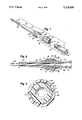
- FIG. 1 is an exploded view of the self locking guide catheter.
- FIG. 2 is a cross sectional view of the assembled self locking guide catheter assembly in which some elements that cannot be seen in FIG. 1 are visible.
- FIG. 3 is a cross sectional view taken along lines 3--3 of FIG. 2 and illustrates the ratchet mechanism of luer segment 1 and central segment 2.
- FIG. 1 is an exploded view of the self locking guide catheter showing each component part isolated and aligned along the central axis of the guide catheter. It should be noted that, when assembling the component parts shown in this view, the guide catheter shaft 4 should first be inserted through the proximal end of the central segment 2 such that flared end 18 is located between concave frusta-conical surface 12 of central segment 2 and convex frusta-conical surface 9 of luer segment 1.
- the luer segment 1 has a generally cylindrical shape and is molded as a single piece from rigid plastic material such as polycarbonate.
- a lumen 6 extends axially through the center of luer segment.
- the proximal end of lumen 6 includes a tapered section 29.
- An accessary such as a syringe can be connected to the proximal end of the guide catheter through a female luer lock that includes luer threads 8 and tapered section 29.
- the external screw threads 5 and external ratchet member 7 function to secure luer segment 1 to the central segment 2 and to the guide catheter shaft 4.
- the central segment 2 which has a generally cylindrical shape is molded as a single piece from rigid plastic material such as polycarbonate.
- the central segment 2 has an internal port 11 extending centrally thereof.
- At the proximal end of internal port 11 there is an internal ratchet area 13 and distally of internal ratchet 13 is an area of internal screw threads 10.
- Distally of the internal screw threads 10 there is a concave frusta-conical surface 12 which is not seen in FIG. 1.
- a tubular extension 20 protrudes from the central distal end of central segment 2.
- a pair of longitudinally extending diametrically opposed members 14 having T-shaped cross sections protrude from the generally cylindrical shaped surface of the central segment 2.
- the diametrically opposed members 14 and the generally cylindrical surface of the central segment 2 form seats 19 over which the slotted ears 17 are received, as shall be discussed in greater detail.
- the control member 24 When luer segment 1 has been connected to central segment 2 this subassembly is referred to as the control member 24.
- the luer segment 1 and central segment 2 function to secure the guide catheter shaft 4 to the control member 24.
- the securement of guide catheter shaft 4 to control member 24 is accomplished by locating the flared end 18 of guide catheter shaft 4 between the concave frusta-conical surface 12 of the central segment 2 and the convex frusta-conical surface 9 of the luer segment 1 with the distal end of guide catheter shaft 4 extending out the distal end of central segment 2.
- With the components so located luer segment 1 is threaded into central segment 2 through the engagement of external screw threads 5 with internal screw threads 10.
- This threaded engagement advances external ratchet member 7 toward internal ratchet area 13 and when this engagement is reached a ratchet effect occurs.
- the ratchet effect begins when the perpendicular distance between frusta-conical surfaces 9 and 12 is between two and ten times the wall thickness of the guide catheter shaft 4.
- the luer segment 1 can be advanced further toward central segment 2 to thus move convex frusta-conical surface 9 closer to concave frusta-conical surface 12 to thus tighten the seal on flared end 18, but once ratcheting starts luer segment 1 cannot be backed away from central segment 2.
- This is the self locking feature of this invention and has the advantage that once the seal between the guide catheter shaft 4 and the control member 24 has been made it cannot be lost as a result of vibrations or accidental unscrewing of one member relative to the other.
- the strain relief/torquer 3 has the general shape of an externally tapered longitudinal member having a pair of rearwardly extending ears 17.
- the strain relief/torquer 3 is molded as a single piece from an elastomeric material such that it is relatively soft and elastic.
- the external conical surface 16 serves as a gripping area that the physician can grasp and roll through his or her finger and thumb to facilitate maneuvering of the guide catheter.
- the external conical surface 16 can be textured to further enhance maneuverability.
- the strain relief/torquer 3 has an internal port 15 that extends centrally through its entire length. At the proximal end of the internal port 15 there is formed an internal cylindrical surface portion 22 that is adapted to receive the tubular extension 20 of central segment 2.
- the rearwardly extending ears 17 have elongated slots 23 formed therein.
- the strain relief/torquer 3 also functions to relieve the strain that is placed on the guide catheter shaft 4 at the point where it exits the distal end of the central segment 2.
- a major longitudinal portion of the strain relief/torquer 3 closely surrounds the outer surface of the guide catheter shaft 4 and thus prevents the guide catheter shaft 4 from being kinked or bent sharply.
- the rearwardly extending ears 17 fit over the diametrically opposed members 14 of the central segment 2 into the seats 19.
- the thickness of rearwardly extending ears 17 is substantially equal to the upright portion of the T-shaped diametrically opposed members 14.
- the width of rearwardly extending ears 17 is greater than the width of the horizontal portion of the T-shaped diametrically opposed members 14.
- the rearwardly extending ears 17 are dimensioned such that they are wider than the width of the horizontal portions of the T-shaped diametrically opposed members 14 they function to pad the edges of the horizontal portions of the T-shaped members 14. Thus if the physician were to grasp the guide catheter in the area of the central segment 2 his or her fingers will encounter the soft elastomeric material of the ears 17 rather than the harder plastic material of the central segment 2.
- the guide catheter shaft 4 is made of a thermoplastic material and its proximal end is plastically deformed into a flared end by, for example placing the end over a heated mandrel. It is important that the flared end 18 be integral with the tubular portion of the guide catheter shaft 4 so that there can be no leakage at this intersection. As seen in FIG. 2 guide catheter shaft 4 is open at its distal end 40 and is of conventional design and functions in the conventional manner.
- FIG. 2 is a cross sectional view of the assembled self locking guide catheter.
- FIG. 2 is a cross sectional view of the guide catheter, in the area of the diametrically opposed members 14 and pairs of ears 17 the cross section is offset slightly such that it passes though the longitudinally extending portions of the pairs of ears 17 rather than through the upright portion of the diametrically opposed members 14.
- the lumen 6 extends through the entire length of luer segment 1 however changes in diameter through its extent.
- the proximal end of the lumen 6 includes a tapered portion 29 which is intended to receive a male luer connector that is secured to the luer segment 1 by luer threads 8.
- FIG. 2 The sealing relationship, previously discussed, between convex frusta-conical surface 9, flared end 18, and concave frusta-conical surface 12 can be best visualized in FIG. 2. For the purpose of clarity there is shown a gap between frusta-conical surface 9 and the surface of flared end 18 and between concave frusta-conical surface 12 and the surface of flared end 18. However it should be understood that when the guide catheter is assembled and in locked position, there are no gaps in these areas. In fact flared end 18 is compressed between convex frusta-conical surface 9 and concave frusta-conical surface 12 such that a seal is formed at this juncture that will withstand the high pressures that are encountered internally of the guide catheter.
- the luer segment 1 is connected to the central segment 2 by threading the external screw threads 5 of luer segment 1 into the internal screw threads 10 of central segment 2. This causes the external ratchet member 7 of luer segment 1 to approach the internal ratchet 13 of central segment 2.
- external ratchet 7 engages internal ratchet 13 a ratcheting occurs between ratchet members 7 and 13 that will permit further movement of luer segment 1 into central segment 2 but will prevent the withdrawal of luer segment 1 from central segment 2.
- convex frusta-conical surface 9 moves toward concave frusta-conical surface 12 the flared end 18 of guide catheter shaft 4 is sealed therebetween.
- the internal port 15 of strain relief/torquer 3 has, at its proximal end, an internal cylindrical surface portion 22 that fits snugly over the tubular extension 20 of central segment 2 and the pairs of ears 17 are expanded to fit over the diametrically opposed members 14 and fit into the seats 19.
- the connection between the pairs of ears 17 and the diametrically opposed members 14 function to hold the strain relief/torquer 3 in place on the central segment 2 and prevent axially movement therebetween.
- the functions of strain relief/torquer 3 relieving strain in the guide catheter shaft 4, can be best visualized with reference to FIG. 2.
- FIG. 3 illustrates how the external ratchet 7 of luer segment 1 can be rotated in the clockwise direction relative to the internal ratchet 13 of central segment 2 but cannot be rotated in the opposite direction.
- the internal ratchet 13 has a plurality of tooth shaped recessions 25 each including an inclined surface 26.
- the external ratchet 7 has a plurality of teeth 27 each including an inclined surface 28.
- the sleeve like portion of the central segment 2 that has the internal ratchet 13 formed on its internal surface, can flex sufficiently to allow inclined surfaces 28 of teeth 27 to slide up the inclined surfaces 26 of tooth shaped recessions 25 thereby flexing the sleeve like portion of central segment 2 outwardly sufficient for the teeth 27 to advance to the next tooth shaped recession 25.
- an attempt is made to rotate the external ratchet area member 7 in the counterclockwise direction the leading edges or points of teeth 27 will be urged into the bottom of tooth receiving shaped recessions 25 and rotation, in this direction, will be prevented.
Abstract
Description
Claims (17)
Priority Applications (1)
| Application Number | Priority Date | Filing Date | Title |
|---|---|---|---|
| US07/888,748 US5224939A (en) | 1992-05-22 | 1992-05-22 | Self locking guide catheter |
Applications Claiming Priority (1)
| Application Number | Priority Date | Filing Date | Title |
|---|---|---|---|
| US07/888,748 US5224939A (en) | 1992-05-22 | 1992-05-22 | Self locking guide catheter |
Publications (1)
| Publication Number | Publication Date |
|---|---|
| US5224939A true US5224939A (en) | 1993-07-06 |
Family
ID=25393814
Family Applications (1)
| Application Number | Title | Priority Date | Filing Date |
|---|---|---|---|
| US07/888,748 Expired - Lifetime US5224939A (en) | 1992-05-22 | 1992-05-22 | Self locking guide catheter |
Country Status (1)
| Country | Link |
|---|---|
| US (1) | US5224939A (en) |
Cited By (57)
| Publication number | Priority date | Publication date | Assignee | Title |
|---|---|---|---|---|
| US5389090A (en) * | 1994-02-07 | 1995-02-14 | Cathco, Inc. | Guiding catheter with straightening dilator |
| US5492530A (en) * | 1994-02-07 | 1996-02-20 | Cathco, Inc. | Method for accessing the coronary arteries from the radial or brachial artery in the arm |
| EP0856332A1 (en) * | 1997-01-31 | 1998-08-05 | Becton, Dickinson and Company | Adapter for mounting a fluid handling device on a catheter tubing |
| US5971958A (en) * | 1995-04-21 | 1999-10-26 | Medtronic Ave Inc. | Interlocking catheter assembly |
| GB2353078A (en) * | 1999-08-10 | 2001-02-14 | Nmt Group Plc | Automatic locking threaded connector |
| US6454745B1 (en) | 1999-11-10 | 2002-09-24 | Nmt Group, Plc | Seal |
| US6500285B2 (en) | 1999-08-23 | 2002-12-31 | Scimed Life Systems, Inc. | Method of making a catheter having interlocking ribbed bond regions |
| US20030060803A1 (en) * | 2001-09-21 | 2003-03-27 | Mcglinch Timothy | Intravascular device with carrier tube engagement member |
| US20030125713A1 (en) * | 2001-09-21 | 2003-07-03 | Mcglinch Timothy | Intravascular device and carrier tube with interference fit member |
| US20030149422A1 (en) * | 2002-02-04 | 2003-08-07 | Charles Muller | Steerable catheter |
| US20040006312A1 (en) * | 1999-11-10 | 2004-01-08 | Donnan Jeremy Francis | Hypodermic syringes |
| US20040018113A1 (en) * | 2002-07-26 | 2004-01-29 | Harvinder Sahota | Method of inhibiting restenosis |
| US20080097223A1 (en) * | 2006-10-20 | 2008-04-24 | Infraredx, Inc. | Optical Catheter Carriage Interlock System and Method |
| US20080097224A1 (en) * | 2006-10-20 | 2008-04-24 | Infraredx, Inc. | Manual and Motor Driven Optical Pullback and Rotation System and Method |
| US20080097408A1 (en) * | 2006-10-20 | 2008-04-24 | Infraredx, Inc. | Pullback Carriage Interlock System and Method for Catheter System |
| US20080097158A1 (en) * | 2006-10-20 | 2008-04-24 | Infraredx, Inc. | Noise Suppression System and Method in Catheter Pullback and Rotation System |
| US20090143768A1 (en) * | 2007-04-23 | 2009-06-04 | Interventional & Surgical Innovations, Llc | Guidewire with adjustable stiffness |
| US20090163859A1 (en) * | 2007-12-21 | 2009-06-25 | Tyco Healthcare Group Lp | Anti-Rotation and Removal Resistant Adapter for Use With a Syringe |
| US20100094399A1 (en) * | 2001-04-30 | 2010-04-15 | C. R. Bard, Inc. | Variable speed self-expanding stent delivery system and luer locking connector |
| US20100143862A1 (en) * | 2007-04-05 | 2010-06-10 | In-Whan Lee | Needle unit for endodontic treatment |
| US7935141B2 (en) | 2005-08-17 | 2011-05-03 | C. R. Bard, Inc. | Variable speed stent delivery system |
| US20110306900A1 (en) * | 2010-06-10 | 2011-12-15 | WindCrest, LLC | Guidewire control device |
| US20130144246A1 (en) * | 2010-06-30 | 2013-06-06 | Terumo Kabushiki Kaisha | Connector and connector assembly |
| US8500789B2 (en) | 2007-07-11 | 2013-08-06 | C. R. Bard, Inc. | Device for catheter sheath retraction |
| US8808346B2 (en) | 2006-01-13 | 2014-08-19 | C. R. Bard, Inc. | Stent delivery system |
| US9078779B2 (en) | 2006-08-07 | 2015-07-14 | C. R. Bard, Inc. | Hand-held actuator device |
| US9114242B2 (en) | 2005-07-06 | 2015-08-25 | Icu Medical, Inc. | Medical connector |
| US9168366B2 (en) | 2008-12-19 | 2015-10-27 | Icu Medical, Inc. | Medical connector with closeable luer connector |
| WO2015171416A1 (en) * | 2014-05-07 | 2015-11-12 | St. Jude Medical, Cardiology Division, Inc. | Threaded, locking handle mechanism for attaching to shaft |
| US9345853B2 (en) * | 2010-12-10 | 2016-05-24 | Teknor Apex Company | Tube assembly and method for making the assembly |
| US20160143722A1 (en) * | 2013-02-15 | 2016-05-26 | BiO2 Medical, Inc. | Temporary filter retrieval apparatus and method |
| US9387308B2 (en) | 2007-04-23 | 2016-07-12 | Cardioguidance Biomedical, Llc | Guidewire with adjustable stiffness |
| EP3115076A4 (en) * | 2014-03-04 | 2017-10-25 | Terumo Kabushiki Kaisha | Catheter |
| US9801745B2 (en) | 2010-10-21 | 2017-10-31 | C.R. Bard, Inc. | System to deliver a bodily implant |
| US20180071485A1 (en) * | 2016-09-14 | 2018-03-15 | Boston Scientific Scimed, Inc. | Catheter hubs |
| WO2018053148A1 (en) * | 2016-09-14 | 2018-03-22 | Boston Scientific Scimed, Inc | Catheter hubs |
| US9933094B2 (en) | 2011-09-09 | 2018-04-03 | Icu Medical, Inc. | Medical connectors with fluid-resistant mating interfaces |
| US10842982B2 (en) | 2005-07-06 | 2020-11-24 | Icu Medical, Inc. | Medical connector |
| US20200375622A1 (en) * | 2012-02-29 | 2020-12-03 | Procept Biorobotics Corporation | Automated image-guided tissue resection and treatment |
| US11026822B2 (en) | 2006-01-13 | 2021-06-08 | C. R. Bard, Inc. | Stent delivery system |
| US11065419B2 (en) | 2017-05-26 | 2021-07-20 | Piper Access, Llc | Catheter delivery devices, systems, and methods |
| US11399844B2 (en) * | 2019-03-26 | 2022-08-02 | Cook Medical Technologies Llc | Medical device holding and delivery assembly and kit therefor |
| US11617861B2 (en) | 2014-06-17 | 2023-04-04 | St. Jude Medical, Cardiology Division, Inc. | Triple coil catheter support |
| US11622806B2 (en) | 2010-04-09 | 2023-04-11 | St Jude Medical International Holding S.À R.L. | Control handle for a contact force ablation catheter |
| US11642063B2 (en) | 2018-08-23 | 2023-05-09 | St. Jude Medical, Cardiology Division, Inc. | Curved high density electrode mapping catheter |
| US11642064B2 (en) | 2015-10-21 | 2023-05-09 | St. Jude Medical, Cardiology Division, Inc. | High density electrode mapping catheter |
| US11647935B2 (en) | 2017-07-24 | 2023-05-16 | St. Jude Medical, Cardiology Division, Inc. | Masked ring electrodes |
| US11672947B2 (en) | 2017-11-28 | 2023-06-13 | St. Jude Medical, Cardiology Division, Inc. | Lumen management catheter |
| US11696716B2 (en) | 2008-12-29 | 2023-07-11 | St. Jude Medical, Atrial Fibrillation Division, Inc. | Non-contact electrode basket catheters with irrigation |
| US11707229B2 (en) | 2015-05-08 | 2023-07-25 | St Jude Medical International Holding S.À R.L. | Integrated sensors for medical devices and method of making integrated sensors for medical devices |
| US11759258B2 (en) | 2008-03-06 | 2023-09-19 | Aquabeam, Llc | Controlled ablation with laser energy |
| US11786705B2 (en) | 2016-10-24 | 2023-10-17 | St. Jude Medical, Cardiology Division, Inc. | Catheter insertion devices |
| US11826172B2 (en) | 2014-05-06 | 2023-11-28 | St. Jude Medical, Cardiology Division, Inc. | Electrode support structure assembly |
| US11839424B2 (en) | 2010-05-05 | 2023-12-12 | St. Jude Medical, Atrial Fibrillation Division, Inc | Monitoring, managing and/or protecting system and method for non-targeted tissue |
| US11844910B2 (en) | 2014-06-05 | 2023-12-19 | St. Jude Medical, Cardiology Division, Inc. | Deflectable catheter shaft section |
| US11896284B2 (en) | 2007-12-28 | 2024-02-13 | St. Jude Medical, Atrial Fibrillation Division, Inc | System and method for measurement of an impedance using a catheter such as an ablation catheter |
| US11918762B2 (en) | 2018-10-03 | 2024-03-05 | St. Jude Medical, Cardiology Division, Inc. | Reduced actuation force electrophysiology catheter handle |
Citations (10)
| Publication number | Priority date | Publication date | Assignee | Title |
|---|---|---|---|---|
| US4191185A (en) * | 1977-09-06 | 1980-03-04 | Johnson & Johnson | Catheter assembly |
| US4391029A (en) * | 1978-12-18 | 1983-07-05 | Baxter Travenol Laboratories Inc. | Catheter hub assembly |
| US4547194A (en) * | 1984-03-16 | 1985-10-15 | Moorehead Harvey R | Hub assemblies and extensions for indwelling catheter tubes and method |
| US4582181A (en) * | 1983-08-12 | 1986-04-15 | Advanced Cardiovascular Systems, Inc. | Steerable dilatation catheter |
| US4785858A (en) * | 1986-07-25 | 1988-11-22 | Farmitalia Carlo Erba S.P.A. | Device for firmly locking a syringe on a body which may be coupled thereto |
| US4969879A (en) * | 1988-07-26 | 1990-11-13 | Gish Biomedical, Inc. | Body fluid interconnect |
| FR2650957A1 (en) * | 1989-08-17 | 1991-02-22 | Kaysersberg Sa | Removable connection piece for a catheter, and method for positioning the connection piece on a catheter |
| US5047021A (en) * | 1989-08-29 | 1991-09-10 | Utterberg David S | Male luer lock medical fitting |
| US5053015A (en) * | 1989-08-30 | 1991-10-01 | The Kendall Company | Locking catheter adapter |
| US5117839A (en) * | 1990-09-18 | 1992-06-02 | Lake Region Manufacturing Co., Inc. | Exchangeable fixed wire catheter |
-
1992
- 1992-05-22 US US07/888,748 patent/US5224939A/en not_active Expired - Lifetime
Patent Citations (10)
| Publication number | Priority date | Publication date | Assignee | Title |
|---|---|---|---|---|
| US4191185A (en) * | 1977-09-06 | 1980-03-04 | Johnson & Johnson | Catheter assembly |
| US4391029A (en) * | 1978-12-18 | 1983-07-05 | Baxter Travenol Laboratories Inc. | Catheter hub assembly |
| US4582181A (en) * | 1983-08-12 | 1986-04-15 | Advanced Cardiovascular Systems, Inc. | Steerable dilatation catheter |
| US4547194A (en) * | 1984-03-16 | 1985-10-15 | Moorehead Harvey R | Hub assemblies and extensions for indwelling catheter tubes and method |
| US4785858A (en) * | 1986-07-25 | 1988-11-22 | Farmitalia Carlo Erba S.P.A. | Device for firmly locking a syringe on a body which may be coupled thereto |
| US4969879A (en) * | 1988-07-26 | 1990-11-13 | Gish Biomedical, Inc. | Body fluid interconnect |
| FR2650957A1 (en) * | 1989-08-17 | 1991-02-22 | Kaysersberg Sa | Removable connection piece for a catheter, and method for positioning the connection piece on a catheter |
| US5047021A (en) * | 1989-08-29 | 1991-09-10 | Utterberg David S | Male luer lock medical fitting |
| US5053015A (en) * | 1989-08-30 | 1991-10-01 | The Kendall Company | Locking catheter adapter |
| US5117839A (en) * | 1990-09-18 | 1992-06-02 | Lake Region Manufacturing Co., Inc. | Exchangeable fixed wire catheter |
Cited By (94)
| Publication number | Priority date | Publication date | Assignee | Title |
|---|---|---|---|---|
| US5389090A (en) * | 1994-02-07 | 1995-02-14 | Cathco, Inc. | Guiding catheter with straightening dilator |
| US5492530A (en) * | 1994-02-07 | 1996-02-20 | Cathco, Inc. | Method for accessing the coronary arteries from the radial or brachial artery in the arm |
| US5971958A (en) * | 1995-04-21 | 1999-10-26 | Medtronic Ave Inc. | Interlocking catheter assembly |
| US6171281B1 (en) | 1995-04-21 | 2001-01-09 | Medtronic Ave, Inc. | Interlocking catheter assembly |
| EP0856332A1 (en) * | 1997-01-31 | 1998-08-05 | Becton, Dickinson and Company | Adapter for mounting a fluid handling device on a catheter tubing |
| GB2353078B (en) * | 1999-08-10 | 2003-03-05 | Nmt Group Plc | Threaded connection |
| GB2353078A (en) * | 1999-08-10 | 2001-02-14 | Nmt Group Plc | Automatic locking threaded connector |
| US6500285B2 (en) | 1999-08-23 | 2002-12-31 | Scimed Life Systems, Inc. | Method of making a catheter having interlocking ribbed bond regions |
| US6454745B1 (en) | 1999-11-10 | 2002-09-24 | Nmt Group, Plc | Seal |
| US20040006312A1 (en) * | 1999-11-10 | 2004-01-08 | Donnan Jeremy Francis | Hypodermic syringes |
| US8062344B2 (en) | 2001-04-30 | 2011-11-22 | Angiomed Gmbh & Co. Medizintechnik Kg | Variable speed self-expanding stent delivery system and luer locking connector |
| US20100094399A1 (en) * | 2001-04-30 | 2010-04-15 | C. R. Bard, Inc. | Variable speed self-expanding stent delivery system and luer locking connector |
| US20030060803A1 (en) * | 2001-09-21 | 2003-03-27 | Mcglinch Timothy | Intravascular device with carrier tube engagement member |
| US20030125713A1 (en) * | 2001-09-21 | 2003-07-03 | Mcglinch Timothy | Intravascular device and carrier tube with interference fit member |
| US7625365B2 (en) * | 2001-09-21 | 2009-12-01 | Boston Scientific Scimed, Inc. | Intravascular device and carrier tube with interference fit member |
| US7214220B2 (en) * | 2001-09-21 | 2007-05-08 | Boston Scientific Scimed, Inc. | Intravascular device with carrier tube engagement member |
| US7025759B2 (en) * | 2002-02-04 | 2006-04-11 | Ebi, L.P. | Steerable catheter |
| US20030149422A1 (en) * | 2002-02-04 | 2003-08-07 | Charles Muller | Steerable catheter |
| US7241284B2 (en) * | 2002-07-26 | 2007-07-10 | Harvinder Sahota | Method of inhibiting restenosis |
| US20040018113A1 (en) * | 2002-07-26 | 2004-01-29 | Harvinder Sahota | Method of inhibiting restenosis |
| US10842982B2 (en) | 2005-07-06 | 2020-11-24 | Icu Medical, Inc. | Medical connector |
| US9724504B2 (en) | 2005-07-06 | 2017-08-08 | Icu Medical, Inc. | Medical connector |
| US9126028B2 (en) | 2005-07-06 | 2015-09-08 | Icu Medical, Inc. | Medical connector |
| US9126029B2 (en) | 2005-07-06 | 2015-09-08 | Icu Medical, Inc. | Medical connector |
| US9114242B2 (en) | 2005-07-06 | 2015-08-25 | Icu Medical, Inc. | Medical connector |
| US7935141B2 (en) | 2005-08-17 | 2011-05-03 | C. R. Bard, Inc. | Variable speed stent delivery system |
| US11026822B2 (en) | 2006-01-13 | 2021-06-08 | C. R. Bard, Inc. | Stent delivery system |
| US9675486B2 (en) | 2006-01-13 | 2017-06-13 | C.R. Bard, Inc. | Stent delivery system |
| US8808346B2 (en) | 2006-01-13 | 2014-08-19 | C. R. Bard, Inc. | Stent delivery system |
| US10993822B2 (en) | 2006-08-07 | 2021-05-04 | C. R. Bard, Inc. | Hand-held actuator device |
| US9078779B2 (en) | 2006-08-07 | 2015-07-14 | C. R. Bard, Inc. | Hand-held actuator device |
| US20080097223A1 (en) * | 2006-10-20 | 2008-04-24 | Infraredx, Inc. | Optical Catheter Carriage Interlock System and Method |
| US20080097408A1 (en) * | 2006-10-20 | 2008-04-24 | Infraredx, Inc. | Pullback Carriage Interlock System and Method for Catheter System |
| US20080097158A1 (en) * | 2006-10-20 | 2008-04-24 | Infraredx, Inc. | Noise Suppression System and Method in Catheter Pullback and Rotation System |
| US20080097224A1 (en) * | 2006-10-20 | 2008-04-24 | Infraredx, Inc. | Manual and Motor Driven Optical Pullback and Rotation System and Method |
| US20100143862A1 (en) * | 2007-04-05 | 2010-06-10 | In-Whan Lee | Needle unit for endodontic treatment |
| US9351804B2 (en) * | 2007-04-05 | 2016-05-31 | In-Whan Lee | Needle unit for endodontic treatment |
| US10258773B2 (en) | 2007-04-23 | 2019-04-16 | Cardioguidance Biomedical, Llc | Guidewire with adjustable stiffness |
| US9387308B2 (en) | 2007-04-23 | 2016-07-12 | Cardioguidance Biomedical, Llc | Guidewire with adjustable stiffness |
| US9387309B2 (en) | 2007-04-23 | 2016-07-12 | Cardioguidance Biomedical, Llc | Guidewire with adjustable stiffness |
| US9498603B2 (en) | 2007-04-23 | 2016-11-22 | Cardioguidance Biomedical, Llc | Guidewire with adjustable stiffness |
| US20090143768A1 (en) * | 2007-04-23 | 2009-06-04 | Interventional & Surgical Innovations, Llc | Guidewire with adjustable stiffness |
| US10398887B2 (en) | 2007-05-16 | 2019-09-03 | Icu Medical, Inc. | Medical connector |
| US11786715B2 (en) | 2007-05-16 | 2023-10-17 | Icu Medical, Inc. | Medical connector |
| US11026821B2 (en) | 2007-07-11 | 2021-06-08 | C. R. Bard, Inc. | Device for catheter sheath retraction |
| US8500789B2 (en) | 2007-07-11 | 2013-08-06 | C. R. Bard, Inc. | Device for catheter sheath retraction |
| US9421115B2 (en) | 2007-07-11 | 2016-08-23 | C. R. Bard, Inc. | Device for catheter sheath retraction |
| US10206800B2 (en) | 2007-07-11 | 2019-02-19 | C.R. Bard, Inc. | Device for catheter sheath retraction |
| US20090163859A1 (en) * | 2007-12-21 | 2009-06-25 | Tyco Healthcare Group Lp | Anti-Rotation and Removal Resistant Adapter for Use With a Syringe |
| US8870833B2 (en) | 2007-12-21 | 2014-10-28 | Covidien Lp | Anti-rotation and removal resistant adapter for use with a syringe |
| US11896284B2 (en) | 2007-12-28 | 2024-02-13 | St. Jude Medical, Atrial Fibrillation Division, Inc | System and method for measurement of an impedance using a catheter such as an ablation catheter |
| US11759258B2 (en) | 2008-03-06 | 2023-09-19 | Aquabeam, Llc | Controlled ablation with laser energy |
| US9168366B2 (en) | 2008-12-19 | 2015-10-27 | Icu Medical, Inc. | Medical connector with closeable luer connector |
| US11478624B2 (en) | 2008-12-19 | 2022-10-25 | Icu Medical, Inc. | Medical connector with closeable luer connector |
| US10046154B2 (en) | 2008-12-19 | 2018-08-14 | Icu Medical, Inc. | Medical connector with closeable luer connector |
| US10716928B2 (en) | 2008-12-19 | 2020-07-21 | Icu Medical, Inc. | Medical connector with closeable luer connector |
| US11696716B2 (en) | 2008-12-29 | 2023-07-11 | St. Jude Medical, Atrial Fibrillation Division, Inc. | Non-contact electrode basket catheters with irrigation |
| US11622806B2 (en) | 2010-04-09 | 2023-04-11 | St Jude Medical International Holding S.À R.L. | Control handle for a contact force ablation catheter |
| US11839424B2 (en) | 2010-05-05 | 2023-12-12 | St. Jude Medical, Atrial Fibrillation Division, Inc | Monitoring, managing and/or protecting system and method for non-targeted tissue |
| US10675448B2 (en) * | 2010-06-10 | 2020-06-09 | Parker-Hannifin Corporation | Guidewire control device |
| US20110306900A1 (en) * | 2010-06-10 | 2011-12-15 | WindCrest, LLC | Guidewire control device |
| US20130144246A1 (en) * | 2010-06-30 | 2013-06-06 | Terumo Kabushiki Kaisha | Connector and connector assembly |
| US10952879B2 (en) | 2010-10-21 | 2021-03-23 | C. R. Bard, Inc. | System to deliver a bodily implant |
| US9801745B2 (en) | 2010-10-21 | 2017-10-31 | C.R. Bard, Inc. | System to deliver a bodily implant |
| US9345853B2 (en) * | 2010-12-10 | 2016-05-24 | Teknor Apex Company | Tube assembly and method for making the assembly |
| US10697570B2 (en) | 2011-09-09 | 2020-06-30 | Icu Medical, Inc. | Axially engaging medical connector system with diminished fluid remnants |
| US9933094B2 (en) | 2011-09-09 | 2018-04-03 | Icu Medical, Inc. | Medical connectors with fluid-resistant mating interfaces |
| US11168818B2 (en) | 2011-09-09 | 2021-11-09 | Icu Medical, Inc. | Axially engaging medical connector system that inhibits fluid penetration between mating surfaces |
| US11808389B2 (en) | 2011-09-09 | 2023-11-07 | Icu Medical, Inc. | Medical connectors with luer-incompatible connection portions |
| US10156306B2 (en) | 2011-09-09 | 2018-12-18 | Icu Medical, Inc. | Axially engaging medical connector system with fluid-resistant mating interfaces |
| US20200375622A1 (en) * | 2012-02-29 | 2020-12-03 | Procept Biorobotics Corporation | Automated image-guided tissue resection and treatment |
| US11737776B2 (en) * | 2012-02-29 | 2023-08-29 | Procept Biorobotics Corporation | Automated image-guided tissue resection and treatment |
| US20160143722A1 (en) * | 2013-02-15 | 2016-05-26 | BiO2 Medical, Inc. | Temporary filter retrieval apparatus and method |
| EP3115076A4 (en) * | 2014-03-04 | 2017-10-25 | Terumo Kabushiki Kaisha | Catheter |
| US11826172B2 (en) | 2014-05-06 | 2023-11-28 | St. Jude Medical, Cardiology Division, Inc. | Electrode support structure assembly |
| US10556091B2 (en) | 2014-05-07 | 2020-02-11 | St. Jude Medical, Cardiology Division, Inc. | Threaded, locking handle mechanism for attaching to shaft |
| WO2015171416A1 (en) * | 2014-05-07 | 2015-11-12 | St. Jude Medical, Cardiology Division, Inc. | Threaded, locking handle mechanism for attaching to shaft |
| US20170049994A1 (en) * | 2014-05-07 | 2017-02-23 | St. Jude Medical, Cardiology Division, Inc. | Threaded, locking handle mechanism for attaching to shaft |
| US11844910B2 (en) | 2014-06-05 | 2023-12-19 | St. Jude Medical, Cardiology Division, Inc. | Deflectable catheter shaft section |
| US11617861B2 (en) | 2014-06-17 | 2023-04-04 | St. Jude Medical, Cardiology Division, Inc. | Triple coil catheter support |
| US11707229B2 (en) | 2015-05-08 | 2023-07-25 | St Jude Medical International Holding S.À R.L. | Integrated sensors for medical devices and method of making integrated sensors for medical devices |
| US11642064B2 (en) | 2015-10-21 | 2023-05-09 | St. Jude Medical, Cardiology Division, Inc. | High density electrode mapping catheter |
| US20180071485A1 (en) * | 2016-09-14 | 2018-03-15 | Boston Scientific Scimed, Inc. | Catheter hubs |
| US10953196B2 (en) | 2016-09-14 | 2021-03-23 | Boston Scientific Scimed, Inc. | Catheter hubs |
| WO2018053148A1 (en) * | 2016-09-14 | 2018-03-22 | Boston Scientific Scimed, Inc | Catheter hubs |
| US10737060B2 (en) * | 2016-09-14 | 2020-08-11 | Boston Scientific Scimed, Inc. | Catheter hubs |
| US11786705B2 (en) | 2016-10-24 | 2023-10-17 | St. Jude Medical, Cardiology Division, Inc. | Catheter insertion devices |
| US11065419B2 (en) | 2017-05-26 | 2021-07-20 | Piper Access, Llc | Catheter delivery devices, systems, and methods |
| US11647935B2 (en) | 2017-07-24 | 2023-05-16 | St. Jude Medical, Cardiology Division, Inc. | Masked ring electrodes |
| US11672947B2 (en) | 2017-11-28 | 2023-06-13 | St. Jude Medical, Cardiology Division, Inc. | Lumen management catheter |
| US11813410B2 (en) | 2017-11-28 | 2023-11-14 | St. Jude Medical, Cardiology Division, Inc. | Controllable expandable catheter |
| US11642063B2 (en) | 2018-08-23 | 2023-05-09 | St. Jude Medical, Cardiology Division, Inc. | Curved high density electrode mapping catheter |
| US11918762B2 (en) | 2018-10-03 | 2024-03-05 | St. Jude Medical, Cardiology Division, Inc. | Reduced actuation force electrophysiology catheter handle |
| US11399844B2 (en) * | 2019-03-26 | 2022-08-02 | Cook Medical Technologies Llc | Medical device holding and delivery assembly and kit therefor |
Similar Documents
| Publication | Publication Date | Title |
|---|---|---|
| US5224939A (en) | Self locking guide catheter | |
| US4838269A (en) | Manifold for angioplasty balloon catheter | |
| US5242430A (en) | Limited turn handle for catheter | |
| US5637102A (en) | Dual-type catheter connection system | |
| AU722401B2 (en) | Multiple-type catheter connection system | |
| US5163903A (en) | Catheter exchange system with detachable luer fitting | |
| US5269757A (en) | Catheter with integral steerable guidewire having linear to rotary movement | |
| US5669881A (en) | Vascular introducer system incorporating inflatable occlusion balloon | |
| EP0718004B1 (en) | Exchange accessory for use with a catheter | |
| US4613329A (en) | Catheter placement device | |
| US5117839A (en) | Exchangeable fixed wire catheter | |
| US6228073B1 (en) | Angiography luer hub having wings proximal to the plurality of grips and strain relief | |
| US6068610A (en) | Intravascular catheter with a recoverable guide wire lumen and method of use | |
| US4726374A (en) | Leakproof hemostasis valve | |
| AU675300B2 (en) | Exchangeable guidewire | |
| US5209727A (en) | Guide wire with integral angioplasty balloon | |
| US5263959A (en) | Dottering auger catheter system and method | |
| US4801297A (en) | Catheter having slit tip | |
| US5484409A (en) | Intravascular catheter and method for use thereof | |
| US5129887A (en) | Adjustable manifold for dilatation catheter | |
| US4844092A (en) | Catheter Y-connector with guidewire locking means | |
| US5409470A (en) | Dilatation catheter and guidewire with threaded tip connection | |
| US5395330A (en) | Auto-inflating catheter cuff | |
| US5334148A (en) | Balloon catheter | |
| EP0657140A1 (en) | Catheter system for forming a passage through an arterial blockage prior to atherectomy or angioplasty |
Legal Events
| Date | Code | Title | Description |
|---|---|---|---|
| AS | Assignment |
Owner name: SCIMED LIFE SYSTEMS, INC. A MN CORP., MINNESOTA Free format text: ASSIGNMENT OF ASSIGNORS INTEREST.;ASSIGNORS:HOLMAN, THOMAS J.;PEPIN, HENRY J.;PENNY, WILLIAM H.;REEL/FRAME:006138/0081;SIGNING DATES FROM 19920515 TO 19920520 |
|
| STCF | Information on status: patent grant |
Free format text: PATENTED CASE |
|
| FPAY | Fee payment |
Year of fee payment: 4 |
|
| FPAY | Fee payment |
Year of fee payment: 8 |
|
| FPAY | Fee payment |
Year of fee payment: 12 |
|
| AS | Assignment |
Owner name: BOSTON SCIENTIFIC SCIMED, INC., MINNESOTA Free format text: CHANGE OF NAME;ASSIGNOR:SCIMED LIFE SYSTEMS, INC.;REEL/FRAME:018505/0868 Effective date: 20050101 Owner name: BOSTON SCIENTIFIC SCIMED, INC.,MINNESOTA Free format text: CHANGE OF NAME;ASSIGNOR:SCIMED LIFE SYSTEMS, INC.;REEL/FRAME:018505/0868 Effective date: 20050101 |