US5219283A - Orthodontic bracket, method of making an orthodontic bracket, and method of applying an orthodontic bracket to the tooth - Google Patents
Orthodontic bracket, method of making an orthodontic bracket, and method of applying an orthodontic bracket to the tooth Download PDFInfo
- Publication number
- US5219283A US5219283A US07/781,679 US78167991A US5219283A US 5219283 A US5219283 A US 5219283A US 78167991 A US78167991 A US 78167991A US 5219283 A US5219283 A US 5219283A
- Authority
- US
- United States
- Prior art keywords
- tooth
- particles
- orthodontic bracket
- adhesive
- adhesive layer
- Prior art date
- Legal status (The legal status is an assumption and is not a legal conclusion. Google has not performed a legal analysis and makes no representation as to the accuracy of the status listed.)
- Expired - Fee Related
Links
Images


Classifications
-
- A—HUMAN NECESSITIES
- A61—MEDICAL OR VETERINARY SCIENCE; HYGIENE
- A61C—DENTISTRY; APPARATUS OR METHODS FOR ORAL OR DENTAL HYGIENE
- A61C7/00—Orthodontics, i.e. obtaining or maintaining the desired position of teeth, e.g. by straightening, evening, regulating, separating, or by correcting malocclusions
- A61C7/12—Brackets; Arch wires; Combinations thereof; Accessories therefor
- A61C7/14—Brackets; Fixing brackets to teeth
- A61C7/16—Brackets; Fixing brackets to teeth specially adapted to be cemented to teeth
Definitions
- the present invention relates to orthodontic brackets, and more particularly, an orthodontic bracket having an improved bonding base, and a method for making same.
- orthodontic brackets are typically bonded directly to the teeth of a patient. It has always been important to provide good bonding between the orthodontic bracket and the tooth. Over the years, many improvements have been made to metal orthodontic brackets and the adhesive used to bond the metal brackets to the teeth. As a result, the bonding of typical prior art metal brackets to the teeth has reached generally accepted values.
- aesthetic brackets have become extremely popular. Typically, these aesthetic brackets are made of materials other than metal, and typically are substantially transparent, or tooth-like in color. For example, recently, orthodontic brackets made out of single crystalline material and strengthened glass have been suggested. While these new materials have offered many possibilities in providing brackets with an aesthetically pleasing appearance, the task of bonding these brackets to the tooth has become much more complicated.
- undercuts on the base of crystalline or ceramic brackets. While such undercuts have improved bonding strengths, these undercuts do not provide the same strength typically found with prior art metal brackets.
- Another problem encountered with adhesives for aesthetic brackets is that certain adhesives have been found to detract from the transparent or translucent characteristics of the bracket.
- Applicant has invented an improved orthodontic bracket and method of making same wherein acceptable bonding strengths are obtained while maintaining the attractive aesthetic qualities of the bracket and additionally minimizes the possibility of removing enamel from the tooth.
- an orthodontic bracket having a base portion for attachment to a tooth.
- the base portion is provided with a substantially monolayer of substantially uniform size particles. The particles are secured to the bonding base through the use of an adhesive.
- an orthodontic bracket having a bonding base for attachment to the surface of a tooth comprising the steps of:
- an orthodontic bracket having a bonding base for attachment to the surface of a tooth.
- the bonding base having means for minimizing removal of enamel from the tooth during removal of the bonded bracket from the tooth.
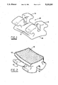
- FIG. 1 is a perspective view of an orthodontic bracket made in accordance with the present invention
- FIG. 2 is a bottom perspective view of the orthodontic bracket of FIG. 1;
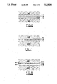
- FIG. 3 is a greatly enlarged partial side elevational view of the bonding base of the bracket of FIG. 1;
- FIG. 4 is a perspective view of the bonding base of FIG. 3;
- FIG. 5 is an exploded side view of the bracket of FIG. 3 shown adjacent the tooth.
- FIG. 6 is an enlarged partial view of a modified bracket made in accordance with the present invention bonded to a tooth;
- FIG. 7 is an enlarged partial view of yet another modified bracket made in accordance with the present invention bonded to a tooth;
- FIG. 8 is an enlarged formatting view of still another bracket made in accordance with the present invention bonded to a tooth.
- FIG. 9 is a schematic representation illustrating one step in making the bracket of FIG. 8.
- the bracket 10 is designed to be attached directly to the tooth of a patient as is customarily done in the prior art.
- the orthodontic bracket 10 comprises a base portion 12 and a pair of tie wings 14 which extend from the base portion 12. Tie wings 14 are each provided with an elongated slot 16 for receiving an orthodontic archwire (not shown) as is customarily done in the prior art.
- the orthodontic bracket 10 is made of a glass material (amorphous or crystalline).
- the bracket 10 may be made out of other suitable materials, for example, ceramics, crystalline and metal.
- the orthodontic bracket 10 in the embodiment illustrated is made out of a transformation-toughened glass material.
- a suitable glass composition for bracket 10 is as follows:
- Base 12 of bracket 10 has a tooth contact surface 18 for placement against the surface of a tooth of a patient.
- Surface 18 is provided with a substantially monolayer 19 of individual particles 20 as illustrated (see FIGS. 3, 4 and 5).
- the particles 20 are of substantially uniform size and have a size in the range of about 5 microns to about 200 microns.
- the size variation in the layer is such that small particles do not completely fill the voids that exist between adjacent particles 20.
- the size variation of particles in layer 19 is such that the smaller particles are not less than about 75% in size of the layer particles, most preferably not less than about 85%.
- the particle 20 are preferably spherical in shape, and preferably have a size in the range of about 40-70 microns.
- particles 20 are made of the same or similar material as base 12.
- pure silica hollow spheres are used and purchased from Emerson and Cuming of Canton, Mass. and identified as SI type microballoon.
- base 12 and particles 20 are made of glass in the embodiment illustrated, it is desirable to enhance or promote adhesion between particle 20 and surface 18.
- One way to accomplish this is by roughening the surface 18 of base 12.
- the bonding base surface 18 is etched with a solution of hydrofluoric acid.
- a solution containing three parts 48% hydrofluoric acid and one part 85% H 3 PO 4 is used to roughen the surface 18.
- the solution is applied to the surface 18 for a predetermined time period. Applicant has found that a time period of approximately in the range of about 30-60 seconds at room temperature is sufficient.
- the base is rinsed with a deionized water for approximately 1 minute.
- the bracket 10 is then allowed to dry. In the preferred embodiment, the bracket 10 is dried at about 100° C. for about 1 hour to assure that all moisture has been removed.
- Adhesion between particles 20 and surface 18 may also be enhanced through the application of an adhesive promoting solution.
- a silane adhesive promoting solution is next applied on the bracket.
- the bracket is appropriately coated by either dipping the entire bracket 10 within the solution or spraying the solution on the base 18. After the solution has been applied, it is appropriately dried. Applicant has found that exposing the bracket 10 at a temperature of about 110° C. for approximately 1 hour is sufficient for drying the bracket 10.
- the surface 18 is roughened and treated with an appropriate adhesion enhancement solution as described, however, it is to be understood that only a single enhancement may be used as described or other suitable treatments may be used as desired or required by the material being used.
- An adhesive resin is then applied onto the bonding base surface 18, preferably a light-curable unfilled adhesive.
- a sufficient amount of the adhesive is applied so as to provide a thin layer, preferably having a thickness in the range of about 0.001 to 0.002 inches.
- the adhesive layer is partially cured so as to render the adhesive tacky. In the particular embodiment illustrated, this is accomplished via a 10 second exposure of the adhesive to a light source capable of curing the adhesive.
- the adhesive is IC2105 produced by Scipharm which comprises a low viscosity dimethacrylate sealant. However, it is to be understood that any other adhesive having the desired strength properties may be used.
- a light adhesive provides a number of advantages in its use, for example, ease and control of particle curing so as to be partially cured which renders the adhesive tacky.
- the particles 20 are then applied to the bonding surface 18.
- the particles 20 comprise hollow glass spheres, however, solid spherical particles may be used if desired.
- Hollow glass spheres are preferred over solid glass spheres in that they assist in providing a weakened area designed to fail prior to removing enamel from the tooth so as to minimize or prevent enamel damage from being removed from the tooth.
- solid glass spheres or irregular shaped particles may be used if desired.
- the glass spheres applied to surface 18 may, if desired, be treated with an adhesive promoting silane solution in the same manner previously discussed with the surface 18.
- the bracket 10 is then placed in a container filled with the glass spheres and moved around until the surface 18 is filled with a substantially monolayer of spheres on surface 18. Since the adhesive is tacky, the spheres will be maintained on surface 18 with a sufficient force so that they will not move under normal manufacturing conditions. The bracket is then removed from the container and any excess particles 20 are easily shaken off.
- the adhesive layer is then fully cured. In the particular embodiment illustrated, this is accomplished by simply exposing the adhesive layer to an appropriate light source, for example, as previously conducted for particle curing, for an appropriate period of time for fully curing the adhesive. In the particular embodiment illustrated, twenty (20) seconds under a Dynamax ultraviolet light has been found to be a sufficient time period to fully cure the adhesive layer. However, it is to be understood that the time period required may be varied as appropriate in accordance with the adhesive system being used.
- the bracket 10 is then bonded to the tooth as is customarily done in the prior art.
- an adhesive is applied to bonding base 18 and particle 20 and the bracket is then applied to the surface of the tooth as is customarily done.
- FIG. 5 there is illustrated a greatly enlarged view of a portion of the bracket 10 as bonded to a tooth 22 illustrating the particles 20 embedded in the adhesive 24 used to bond the bracket 10 to the tooth 22.
- the adhesive 24 may be any suitable adhesive as is typically used. In the particular embodiment illustrated, adhesive 24 is typically used. In the particular embodiment illustrated, adhesive 24 is a filled adhesive sold under the trademark Concise by the 3M Corporation.
- the use of a bonding system that utilizes a substantially monolayer of particles of substantially uniform size adhesively bonded to the base and adhesives for bonding the bracket 10 to the tooth 22 produces a system that yields a fracture plane 28 between the bracket and tooth to occur away from the bond between the tooth 22 and adhesive 24.
- the adhesive used to bond the particles 20 to base 12 is less than the bond strength of the adhesive used to bond the bracket to the tooth 22.
- the amount of adhesive used to bond particles 20 to base 12 the less amount used will generally cause failure of the bond at lower forces.
- the adhesives used to bond particles 20 to base 12 form a relatively small collar 30 around the particles. As more adhesive is applied, the greater the bond strength between the particles 20 and base 12 until reaching a maximum value and will then decrease. Failure of the bond between the bracket 10 and tooth 22 can also be affected by the type and size of particles used. Hollow sphere particles, of course, provide an area which allow rupture of the particles. The size, shape and thickness of the walls of the particles 20 also have an effect on the overall bond strength and failure point.
- the particles 20 and adhesive used provide a bracket/tooth bond that will fail when a force greater than about 30 lbs. is applied to the bracket 10.
- the spheres 20 will either rupture or completely come off base 12. In either event, substantially no enamel is removed from the tooth.
- the present invention provides a bonding system designed to fail at a location away from the tooth adhesive joint 29 so as to minimize or prevent removal of enamel from the surface of the tooth.
- the particle 20, as previously discussed, is made of a glass material which has a resistance to abrasion lower than the tooth enamel or other commonly used material such as single or polycrystalline material and ceramics used to make orthodontic brackets and like appliances.
- a relatively low abrasion resistant material for particles 20 any particles 20 remaining on the tooth can be easily removed by the orthodontist without the need for use of diamond tools and damaging the tooth or causing fast wear to the burs.
- a portion predetermined fracture plane is provided through the use of a plurality of particles 20 adhered to the bonding base surface. It is to be understood that various other structures may be provided for producing a fracture plane disposed away from the tooth adhesive joint.
- FIG. 6 there is illustrated an enlarged front elevational view of a portion of an orthodontic bracket made in accordance with the present invention having a bonding base portion 112 which is adhesively bonded to the tooth 122.
- a first adhesive layer 114 is provided adjacent to the base portion 112 and is preferably of a filled type adhesive.
- a second intermediate adhesive layer 115 is provided adjacent to first adhesive layer 114.
- intermediate adhesive layer 115 is an unfilled adhesive sealant.
- An outer adhesive layer 116 is provided between the tooth 122 and intermediate adhesive layer 115.
- the third adhesive layer is preferably a filled adhesive.
- adhesive layers 114 and 116 comprise a layer of light cure filled bonding adhesive
- second adhesive layer 115 is an unfilled light cure sealant and are of type typically available and presently used in the practice of orthodontics.
- adhesives sold under the trademark Transbond are of type typically available and presently used in the practice of orthodontics.
- the adhesive layers 114 and 116 are designed to possess a shear strength greater than that of the intermediate adhesive layer 115.
- the adhesive layers 114, 116 can withstand a shear load of approximately 30 pounds, whereas the intermediate layer 115 can resist a shear force of about ten pounds.
- bracket tooth assembly provides a predetermined ruptured plane that is away from the bond joint between the adhesive layer 116 and the surface of the tooth 122.
- the adhesive may be applied is a series of steps. First, adhesive layer 114 is placed on the base portion 112 of the bracket and an adhesive layer 116 is placed on the tooth 122. Both layers 114, 116 are then partially cured by exposing the adhesive layers 114, 116 to a curing lamp for approximately 10 seconds. It is, of course, to be understood that the other adhesive may be used requiring other curing techniques. After layers have been partially cured, sealant intermediate layer 115 is applied either to the tooth 122 or the bonding base 112 over the adjacent partially cured adhesive layer 114. The bracket and the tooth are then brought together and the adhesive layers 114, 115, 116 are completely cured.
- the resulting bond strength of the bracket to the tooth will exhibit a strength of approximately 10 pounds, i.e. the strength of the weakest element.
- the bond will break at the weakest point, i.e. being between the intermediate layer 115 and the adjacent layers 114 and 116.
- the sandwich adhesive layer structure as set forth in FIG. 6 may be obtained by other method steps.
- the adhesive layer 114 may be placed on the bonding base portion 112, and thereafter fully cured, in the particular embodiment illustrated by exposing the light cured adhesive to an appropriate light source.
- the cured adhesive layer could be treated with a methacrylic acid solution (for example, 30% ethanol) for about 30 seconds.
- a second adhesive layer 116 is placed on the tooth, and the bracket is brought into contact with the adhesive on the tooth and fully cured with the appropriate light source.
- various other type adhesives may be used having the desired sheer strength in each of the respective layers 114, 115, 116 so that a weaker adhesive layer is formed between the bracket and tooth which is away from the tooth adhesive interface.
- FIG. 7 there is illustrated yet another embodiment made in accordance with the present invention.
- a bracket having a bonding portion 212, which is adhered to a tooth 222.
- a first light curable filled adhesive layer 214 is applied adjacent to the base portion 212.
- a polyvinylchloride (PVC) plastic film is placed adjacent the filled adhesive layer 114 and a second light curable adhesive layer 216 is placed between the tooth and the plastic barrier film layer 215.
- PVC polyvinylchloride
- the thin film layer 115 has a thickness in the range of 0.0005 to approximately 0.0015 inches. Examples of suitable materials are; polyurethane, polyethylene, nylon, etc.
- the surfaces of the film are preferably treated to improve adhesion bonding, for example, chemical grafting, plasma deposition, plasma etching, as is well known in the art.
- the barrier film 215 is a plasticized 55 shore D polyvinylchloride plastic. The surfaces are prepared for bonding by etching the surfaces with a solution of one part pvc monomer and 5 parts cyclohexanone, for fifteen seconds.
- the etched pvc film barrier 215 is placed between conventional adhesive layers 214, 216.
- adhesive layers 214, 216 comprise filled light cured adhesive similar to that discussed in the embodiment in FIGS. 1-5.
- urethane films with a chemically grafted methacrylate functionality as sold by Polymer Research Corporation of Brooklyn, N.Y.
- Alternate grafting methods include plasma deposition of methacrylic acid and the like on the polyurethane surface by plasma deposition as done by Plasma Science Corporation of Belmont, California.
- Film layer 215 provides a weak point which will fail when excess shear force is applied to the bracket tooth assembly. Since the film provides the weakest link in the assembly, failure will occur at this point away from the adhesive 216 tooth interface.
- FIG. 8 there is illustrated another enlarged partial elevational view of the base portion 312 of a bracket made in accordance with the present invention bonded to tooth 322.
- the base portion 312 is provided with a surface preparation that will cause a failure point away from the adhesive tooth joint interface 329.
- a plurality of crystal structure 315 are grown on the base portion 312.
- U.S. Pat. No. 4,600,383 is representative of known techniques that can be employed to grow the crystals.
- the bonding base would be initially provided with a layer 314 of hydroxyapitite sprayed on for example by plasma or vacuum deposition.
- base portion 312 is made out of glass material, similar to that illustrated in FIGS. 1-5.
- crystal structure 315 on the base portion 312 it is necessary to prepare the surface which in the particular case requires the plasma spraying of the hydroxyapitite.
- the outer surface 312 is then prepared with crystal growth solution for bonding.
- the attachment of the adhesive to the bracket by the way of encapsulation of the crystals formed on the base 312 by the adhesive 316.
- the crystals 315 serve as the weak link in the bond joint between the bracket and tooth 332. Thus yielding a fracture plane designed to fail prior to failure of the adhesive tooth joint 329.
- the orthodontic bracket may be made out of other hard materials, such as single crystalline materials, ceramics and polycrystalline materials.
- various types of adhesive systems may be used.
- the particles may take other uniform or irregular shapes.
Abstract
Description
______________________________________
              PERCENTAGE
MATERIAL      (By Weight)
______________________________________
S.sub.i O2    58.8
Al.sub.2 O3   18.5
ZnO           12.5
Li.sub.2 O    5.3
Na.sub.2 O    3.3
Sb.sub.2 O.sub.3
              1.5
K.sub.2 O     .1
______________________________________
Claims (24)
Priority Applications (1)
| Application Number | Priority Date | Filing Date | Title |
|---|---|---|---|
| US07/781,679 US5219283A (en) | 1989-09-28 | 1991-10-24 | Orthodontic bracket, method of making an orthodontic bracket, and method of applying an orthodontic bracket to the tooth |
Applications Claiming Priority (2)
| Application Number | Priority Date | Filing Date | Title |
|---|---|---|---|
| US41362089A | 1989-09-28 | 1989-09-28 | |
| US07/781,679 US5219283A (en) | 1989-09-28 | 1991-10-24 | Orthodontic bracket, method of making an orthodontic bracket, and method of applying an orthodontic bracket to the tooth |
Related Parent Applications (1)
| Application Number | Title | Priority Date | Filing Date |
|---|---|---|---|
| US41362089A Continuation | 1989-09-28 | 1989-09-28 |
Publications (1)
| Publication Number | Publication Date |
|---|---|
| US5219283A true US5219283A (en) | 1993-06-15 |
Family
ID=27022250
Family Applications (1)
| Application Number | Title | Priority Date | Filing Date |
|---|---|---|---|
| US07/781,679 Expired - Fee Related US5219283A (en) | 1989-09-28 | 1991-10-24 | Orthodontic bracket, method of making an orthodontic bracket, and method of applying an orthodontic bracket to the tooth |
Country Status (1)
| Country | Link |
|---|---|
| US (1) | US5219283A (en) |
Cited By (19)
| Publication number | Priority date | Publication date | Assignee | Title |
|---|---|---|---|---|
| US5697787A (en) * | 1994-07-11 | 1997-12-16 | Schumacher; Dieter | Dental inserts |
| US5810584A (en) * | 1997-04-04 | 1998-09-22 | Ormco Corporation | Orthodontic appliances (brackets) having pre-applied adhesive |
| US6050815A (en) * | 1996-03-15 | 2000-04-18 | 3M Innovative Properties Company | Precoated dental cement |
| US20030198913A1 (en) * | 2002-04-18 | 2003-10-23 | 3M Innovative Properties Company | Orthodontic brackets including one part of an at least two-part adhesive on the base of the bracket |
| WO2004041116A2 (en) | 2002-11-01 | 2004-05-21 | Tp Orthodontics, Inc. | Appliance with bilayer base |
| US20050136370A1 (en) * | 2003-12-19 | 2005-06-23 | 3M Innovative Properties Company | Multi-layer adhesives and methods for bonding orthodontic appliances to tooth structure |
| US20050227196A1 (en) * | 2002-03-13 | 2005-10-13 | Christoph Von Mandach | Method for applying orthodontic fixing elements |
| US7131836B1 (en) * | 2002-11-01 | 2006-11-07 | Tp Orthodontics, Inc. | Bracket with bilayer base configured to produce a control value |
| US20070142498A1 (en) * | 2005-12-20 | 2007-06-21 | Brennan Joan V | Dental compositions including thermally responsive additives, and the use thereof |
| US20070141524A1 (en) * | 2005-12-20 | 2007-06-21 | Brennan Joan V | Dental compositions including radiation-to-heat converters, and the use thereof |
| US20070142497A1 (en) * | 2005-12-20 | 2007-06-21 | Kalgutkar Rajdeep S | Methods for reducing bond strengths, dental compositions, and the use thereof |
| US20080096150A1 (en) * | 2006-10-23 | 2008-04-24 | 3M Innovative Properties Company | Dental articles, methods, and kits including a compressible material |
| US20090201875A1 (en) * | 2006-11-01 | 2009-08-13 | Hajime Hasegawa | Device And Method For Radio Communication |
| US20090220920A1 (en) * | 2005-03-01 | 2009-09-03 | Primus Carolyn M | Methods for indirect bonding of orthodontic appliances |
| US20100173256A1 (en) * | 2008-11-14 | 2010-07-08 | Ormco Corporation | Surface Treated Polycrystalline Ceramic Orthodontic Bracket and Method of Making Same |
| US8026296B2 (en) | 2005-12-20 | 2011-09-27 | 3M Innovative Properties Company | Dental compositions including a thermally labile component, and the use thereof |
| US8251696B2 (en) | 2008-08-13 | 2012-08-28 | Ormco Corporation | Aesthetic orthodontic bracket and method of making same |
| US9539065B2 (en) | 2006-10-23 | 2017-01-10 | 3M Innovative Properties Company | Assemblies, methods, and kits including a compressible material |
| US20200229903A1 (en) * | 2019-01-22 | 2020-07-23 | Dean UltraThin Retainer, LLC | Orthodontic appliance with apertured bonding pad |
Citations (22)
| Publication number | Priority date | Publication date | Assignee | Title |
|---|---|---|---|---|
| US3955282A (en) * | 1975-03-03 | 1976-05-11 | Mcnall Earl G | Process of mounting orthodontic bracket to tooth |
| US3975824A (en) * | 1974-04-02 | 1976-08-24 | Brian William Lee | Orthodontic brackets |
| US4050156A (en) * | 1976-06-28 | 1977-09-27 | Daniel Chasanoff | Dental appliance |
| US4165561A (en) * | 1976-04-15 | 1979-08-28 | American Hospital Supply Corporation | Orthodontic appliance with porous tooth-abutting face |
| US4200980A (en) * | 1978-03-06 | 1980-05-06 | Advance Dental Corporation | Orthodontic formulation and method |
| US4216583A (en) * | 1978-08-03 | 1980-08-12 | Zulauf Inc. | Orthodontic appliance |
| US4340529A (en) * | 1980-04-11 | 1982-07-20 | Lee Pharmaceuticals, Inc. | No-mix orthodontic adhesive formulations |
| US4380432A (en) * | 1980-09-03 | 1983-04-19 | Scientific Pharmaceuticals | Method for adhering structures to teeth |
| EP0099741A2 (en) * | 1982-07-21 | 1984-02-01 | Dennis Clifford Smith | Orthodontic attachments |
| US4460336A (en) * | 1982-07-27 | 1984-07-17 | Smith Dennis C | Orthodontic attachments |
| FR2563426A1 (en) * | 1984-04-27 | 1985-10-31 | Cavaf Michel | Orthodontic apparatus |
| US4595598A (en) * | 1984-04-23 | 1986-06-17 | Johnson & Johnson Dental Products Company | Crystalline alumina composites |
| US4600383A (en) * | 1981-02-17 | 1986-07-15 | Dennis Smith Consulting Limited | Bonding to calcified tissues |
| US4604057A (en) * | 1985-07-03 | 1986-08-05 | American Orthodontics Corporation | Cast orthodontic appliance |
| US4626209A (en) * | 1983-04-11 | 1986-12-02 | Unitek Corporation | Orthodontic bracket with metallic coated bonding base |
| US4639218A (en) * | 1984-04-23 | 1987-01-27 | Johnson & Johnson Dental Products Company | Crystalline alumina orthodontic bracket |
| US4661059A (en) * | 1983-09-22 | 1987-04-28 | Yoneo Kanno | Orthodontic bracket and apparatus for fabricating the same |
| US4681538A (en) * | 1984-04-23 | 1987-07-21 | Johnson & Johnson Dental Products, Company | Crystalline alumina composites |
| US4752221A (en) * | 1981-09-15 | 1988-06-21 | Augusta Developments, Inc. | Orthodontic bracket |
| US4784606A (en) * | 1986-10-22 | 1988-11-15 | Johnson & Johnson Consumer Products, Inc. | Orthodontic brackets made from ion exchange strengthened glass |
| US4826430A (en) * | 1984-04-23 | 1989-05-02 | Johnson & Johnson Consumer Products, Inc. | Adhesive primer for alumina brackets |
| US4948366A (en) * | 1987-06-26 | 1990-08-14 | Unitek Corporation | Adhesive bond strength control for orthodontic brackets |
-
1991
- 1991-10-24 US US07/781,679 patent/US5219283A/en not_active Expired - Fee Related
Patent Citations (23)
| Publication number | Priority date | Publication date | Assignee | Title |
|---|---|---|---|---|
| US3975824A (en) * | 1974-04-02 | 1976-08-24 | Brian William Lee | Orthodontic brackets |
| US3955282A (en) * | 1975-03-03 | 1976-05-11 | Mcnall Earl G | Process of mounting orthodontic bracket to tooth |
| US4165561A (en) * | 1976-04-15 | 1979-08-28 | American Hospital Supply Corporation | Orthodontic appliance with porous tooth-abutting face |
| US4050156A (en) * | 1976-06-28 | 1977-09-27 | Daniel Chasanoff | Dental appliance |
| US4200980A (en) * | 1978-03-06 | 1980-05-06 | Advance Dental Corporation | Orthodontic formulation and method |
| US4216583B1 (en) * | 1978-08-03 | 1994-03-01 | Class One Orthodontics, Inc. | |
| US4216583A (en) * | 1978-08-03 | 1980-08-12 | Zulauf Inc. | Orthodontic appliance |
| US4340529A (en) * | 1980-04-11 | 1982-07-20 | Lee Pharmaceuticals, Inc. | No-mix orthodontic adhesive formulations |
| US4380432A (en) * | 1980-09-03 | 1983-04-19 | Scientific Pharmaceuticals | Method for adhering structures to teeth |
| US4600383A (en) * | 1981-02-17 | 1986-07-15 | Dennis Smith Consulting Limited | Bonding to calcified tissues |
| US4752221A (en) * | 1981-09-15 | 1988-06-21 | Augusta Developments, Inc. | Orthodontic bracket |
| EP0099741A2 (en) * | 1982-07-21 | 1984-02-01 | Dennis Clifford Smith | Orthodontic attachments |
| US4460336A (en) * | 1982-07-27 | 1984-07-17 | Smith Dennis C | Orthodontic attachments |
| US4626209A (en) * | 1983-04-11 | 1986-12-02 | Unitek Corporation | Orthodontic bracket with metallic coated bonding base |
| US4661059A (en) * | 1983-09-22 | 1987-04-28 | Yoneo Kanno | Orthodontic bracket and apparatus for fabricating the same |
| US4639218A (en) * | 1984-04-23 | 1987-01-27 | Johnson & Johnson Dental Products Company | Crystalline alumina orthodontic bracket |
| US4681538A (en) * | 1984-04-23 | 1987-07-21 | Johnson & Johnson Dental Products, Company | Crystalline alumina composites |
| US4595598A (en) * | 1984-04-23 | 1986-06-17 | Johnson & Johnson Dental Products Company | Crystalline alumina composites |
| US4826430A (en) * | 1984-04-23 | 1989-05-02 | Johnson & Johnson Consumer Products, Inc. | Adhesive primer for alumina brackets |
| FR2563426A1 (en) * | 1984-04-27 | 1985-10-31 | Cavaf Michel | Orthodontic apparatus |
| US4604057A (en) * | 1985-07-03 | 1986-08-05 | American Orthodontics Corporation | Cast orthodontic appliance |
| US4784606A (en) * | 1986-10-22 | 1988-11-15 | Johnson & Johnson Consumer Products, Inc. | Orthodontic brackets made from ion exchange strengthened glass |
| US4948366A (en) * | 1987-06-26 | 1990-08-14 | Unitek Corporation | Adhesive bond strength control for orthodontic brackets |
Non-Patent Citations (4)
| Title |
|---|
| A Comparison with Foil Mesh by Dr. Hansen, American Journal of Orthodontics, vol. 83, No. 1, Jan. 1983. * |
| Gem Bracket by Ormco. * |
| Unitek/3M Brochure Mechanical Retention, We added something familiar to our ceramic brackets . * |
| Unitek/3M Brochure--Mechanical Retention, "We added something familiar to our ceramic brackets". |
Cited By (34)
| Publication number | Priority date | Publication date | Assignee | Title |
|---|---|---|---|---|
| US5697787A (en) * | 1994-07-11 | 1997-12-16 | Schumacher; Dieter | Dental inserts |
| US6050815A (en) * | 1996-03-15 | 2000-04-18 | 3M Innovative Properties Company | Precoated dental cement |
| US5810584A (en) * | 1997-04-04 | 1998-09-22 | Ormco Corporation | Orthodontic appliances (brackets) having pre-applied adhesive |
| US20050227196A1 (en) * | 2002-03-13 | 2005-10-13 | Christoph Von Mandach | Method for applying orthodontic fixing elements |
| US20030198913A1 (en) * | 2002-04-18 | 2003-10-23 | 3M Innovative Properties Company | Orthodontic brackets including one part of an at least two-part adhesive on the base of the bracket |
| US7217124B2 (en) | 2002-04-18 | 2007-05-15 | 3M Innovative Properties Company | Orthodontic brackets including one part of an at least two-part adhesive on the base of the bracket |
| WO2004041116A2 (en) | 2002-11-01 | 2004-05-21 | Tp Orthodontics, Inc. | Appliance with bilayer base |
| US6746242B1 (en) * | 2002-11-01 | 2004-06-08 | Tp Orthodontics, Inc. | Appliance with bilayer base |
| WO2004041116A3 (en) * | 2002-11-01 | 2005-02-17 | Tp Orthodontics Inc | Appliance with bilayer base |
| USRE45743E1 (en) * | 2002-11-01 | 2015-10-13 | Tp Orthodontics, Inc. | Appliance with bilayer base |
| US7131836B1 (en) * | 2002-11-01 | 2006-11-07 | Tp Orthodontics, Inc. | Bracket with bilayer base configured to produce a control value |
| US7374420B2 (en) * | 2003-12-19 | 2008-05-20 | 3M Innovative Properties Company | Multi-layer adhesives and methods for bonding orthodontic appliances to tooth structure |
| US8784099B2 (en) | 2003-12-19 | 2014-07-22 | 3M Innovative Properties Company | Multi-layer adhesives and methods for bonding orthodontic appliances to tooth structure |
| US20050136370A1 (en) * | 2003-12-19 | 2005-06-23 | 3M Innovative Properties Company | Multi-layer adhesives and methods for bonding orthodontic appliances to tooth structure |
| JP4718488B2 (en) * | 2003-12-19 | 2011-07-06 | スリーエム イノベイティブ プロパティズ カンパニー | Multilayer adhesive and method for bonding orthodontic appliances to tooth structure |
| US20080187878A1 (en) * | 2003-12-19 | 2008-08-07 | 3M Innovative Properties Company | Multi-layer adhesives and methods for bonding orthodontic appliances to tooth structure |
| JP2007514511A (en) * | 2003-12-19 | 2007-06-07 | スリーエム イノベイティブ プロパティズ カンパニー | Multilayer adhesive and method for bonding orthodontic appliances to tooth structure |
| US8308478B2 (en) | 2005-03-01 | 2012-11-13 | Dentsply International Inc. | Methods for indirect bonding of orthodontic appliances |
| US20090220920A1 (en) * | 2005-03-01 | 2009-09-03 | Primus Carolyn M | Methods for indirect bonding of orthodontic appliances |
| US20070141524A1 (en) * | 2005-12-20 | 2007-06-21 | Brennan Joan V | Dental compositions including radiation-to-heat converters, and the use thereof |
| US20070142498A1 (en) * | 2005-12-20 | 2007-06-21 | Brennan Joan V | Dental compositions including thermally responsive additives, and the use thereof |
| US7776940B2 (en) | 2005-12-20 | 2010-08-17 | 3M Innovative Properties Company | Methods for reducing bond strengths, dental compositions, and the use thereof |
| US7896650B2 (en) | 2005-12-20 | 2011-03-01 | 3M Innovative Properties Company | Dental compositions including radiation-to-heat converters, and the use thereof |
| US20070142497A1 (en) * | 2005-12-20 | 2007-06-21 | Kalgutkar Rajdeep S | Methods for reducing bond strengths, dental compositions, and the use thereof |
| US8026296B2 (en) | 2005-12-20 | 2011-09-27 | 3M Innovative Properties Company | Dental compositions including a thermally labile component, and the use thereof |
| US9539065B2 (en) | 2006-10-23 | 2017-01-10 | 3M Innovative Properties Company | Assemblies, methods, and kits including a compressible material |
| US20080096150A1 (en) * | 2006-10-23 | 2008-04-24 | 3M Innovative Properties Company | Dental articles, methods, and kits including a compressible material |
| US10492890B2 (en) | 2006-10-23 | 2019-12-03 | 3M Innovative Properties Company | Assemblies, methods, and kits including a compressible material |
| US11839521B2 (en) | 2006-10-23 | 2023-12-12 | 3M Innovative Properties Company | Assemblies, methods, and kits including a compressible material |
| US20090201875A1 (en) * | 2006-11-01 | 2009-08-13 | Hajime Hasegawa | Device And Method For Radio Communication |
| US8251696B2 (en) | 2008-08-13 | 2012-08-28 | Ormco Corporation | Aesthetic orthodontic bracket and method of making same |
| US20100173256A1 (en) * | 2008-11-14 | 2010-07-08 | Ormco Corporation | Surface Treated Polycrystalline Ceramic Orthodontic Bracket and Method of Making Same |
| US9717569B2 (en) | 2008-11-14 | 2017-08-01 | Ormco Corporation | Surface treated polycrystalline ceramic orthodontic bracket and method of making same |
| US20200229903A1 (en) * | 2019-01-22 | 2020-07-23 | Dean UltraThin Retainer, LLC | Orthodontic appliance with apertured bonding pad |
Similar Documents
| Publication | Publication Date | Title |
|---|---|---|
| US5219283A (en) | Orthodontic bracket, method of making an orthodontic bracket, and method of applying an orthodontic bracket to the tooth | |
| US5964592A (en) | Nonmetallic dental post and method | |
| US5267855A (en) | Bonding base and method of making the same for a plastic orthodontic bracket | |
| US5098304A (en) | Dental materials and process utilizing etched silanated glass fiber | |
| US5110290A (en) | Orthodontic bracket/mesh screen | |
| JP4550275B2 (en) | New prepreg | |
| US5078596A (en) | Orthodontic bracket and associated fabricating method | |
| US4364731A (en) | Methods for producing adhesive bonds between substrate and polymer employing an intermediate oxide layer | |
| US6048203A (en) | Method and device for forming and attaching a non-metal dental prosthesis | |
| US7059850B1 (en) | Attachment devices and methods for a dental appliance | |
| US7125248B2 (en) | Attachment devices and methods for a dental appliance | |
| EP2266491B1 (en) | Device and method for forming attachment devices on a tooth | |
| US5176517A (en) | Dental undercut application device and method of use | |
| US7131836B1 (en) | Bracket with bilayer base configured to produce a control value | |
| US20090280450A1 (en) | Pre-formed hard-shell attachment devices for dental appliances | |
| US7632878B2 (en) | Dental releasing materials | |
| US3250002A (en) | Dental methods employing a cyanoacrylate | |
| US4820157A (en) | Dental bridge | |
| USRE45743E1 (en) | Appliance with bilayer base | |
| US4820545A (en) | Method of bonding ceramic orthodontic appliances | |
| Leesungbok et al. | The effect of IDS (immediate dentin sealing) on dentin bond strength under various thermocycling periods | |
| US4895516A (en) | Intermediate ceramic bonding layer for bonding of a resin to an alloy structure or substructure | |
| CA2101938A1 (en) | Method for improving adhesion to metal | |
| US5810584A (en) | Orthodontic appliances (brackets) having pre-applied adhesive | |
| US5008304A (en) | Orthodontic appliance adhesive |
Legal Events
| Date | Code | Title | Description |
|---|---|---|---|
| AS | Assignment |
Owner name: CHEMICAL BANK, NEW YORK Free format text: SECURITY INTEREST;ASSIGNORS:SYBRON CORP.;ORMCO CORP. A CORP. OF DELAWARE;KERR MANUFACTURING A CORP. OF DELAWARE;AND OTHERS;REEL/FRAME:006667/0903 Effective date: 19930701 |
|
| CC | Certificate of correction | ||
| FPAY | Fee payment |
Year of fee payment: 4 |
|
| FEPP | Fee payment procedure |
Free format text: PAYOR NUMBER ASSIGNED (ORIGINAL EVENT CODE: ASPN); ENTITY STATUS OF PATENT OWNER: LARGE ENTITY |
|
| AS | Assignment |
Owner name: ORMCO CORPORATION, CALIFORNIA Free format text: ASSIGNMENT AND RELINQUISHMENT OF SECURITY INTEREST IN PATENTS AND TRADEMARKS;ASSIGNOR:CHEMICAL BANK;REEL/FRAME:010425/0120 Effective date: 19960423 |
|
| FPAY | Fee payment |
Year of fee payment: 8 |
|
| AS | Assignment |
Owner name: ABN AMRO BANK N.V., ILLINOIS Free format text: SECURITY INTEREST;ASSIGNOR:ORMCO CORPORATION;REEL/FRAME:011400/0232 Effective date: 20001211 |
|
| AS | Assignment |
Owner name: ORMCO CORPORATION, CALIFORNIA Free format text: SECURITY INTEREST;ASSIGNOR:ABN MARO BANK N.V.;REEL/FRAME:012946/0993 Effective date: 20020606 Owner name: CREDIT SUISSE FIRST BOSTON, NEW YORK Free format text: SECURITY AGREEMENT;ASSIGNOR:ORMCO CORPORATION;REEL/FRAME:012958/0243 Effective date: 20020606 |
|
| REMI | Maintenance fee reminder mailed | ||
| LAPS | Lapse for failure to pay maintenance fees | ||
| STCH | Information on status: patent discontinuation |
Free format text: PATENT EXPIRED DUE TO NONPAYMENT OF MAINTENANCE FEES UNDER 37 CFR 1.362 |
|
| FP | Lapsed due to failure to pay maintenance fee |
Effective date: 20050615 |
|
| AS | Assignment |
Owner name: ORMCO CORPORATION, CALIFORNIA Free format text: RELEASE BY SECURED PARTY;ASSIGNOR:CREDIT SUISSE FIRST BOSTON (N/K/A CREDIT SUISSE, CAYMAN ISLANDS BRANCH);REEL/FRAME:017519/0456 Effective date: 20060323 |