US5208043A - Adjustable shims for mold seals - Google Patents
Adjustable shims for mold seals Download PDFInfo
- Publication number
- US5208043A US5208043A US07/467,184 US46718490A US5208043A US 5208043 A US5208043 A US 5208043A US 46718490 A US46718490 A US 46718490A US 5208043 A US5208043 A US 5208043A
- Authority
- US
- United States
- Prior art keywords
- seal
- shell
- molding
- molding apparatus
- seal groove
- Prior art date
- Legal status (The legal status is an assumption and is not a legal conclusion. Google has not performed a legal analysis and makes no representation as to the accuracy of the status listed.)
- Expired - Lifetime
Links
Images


Classifications
-
- B—PERFORMING OPERATIONS; TRANSPORTING
- B29—WORKING OF PLASTICS; WORKING OF SUBSTANCES IN A PLASTIC STATE IN GENERAL
- B29C—SHAPING OR JOINING OF PLASTICS; SHAPING OF MATERIAL IN A PLASTIC STATE, NOT OTHERWISE PROVIDED FOR; AFTER-TREATMENT OF THE SHAPED PRODUCTS, e.g. REPAIRING
- B29C33/00—Moulds or cores; Details thereof or accessories therefor
- B29C33/0038—Moulds or cores; Details thereof or accessories therefor with sealing means or the like
- B29C33/0044—Moulds or cores; Details thereof or accessories therefor with sealing means or the like for sealing off parts of inserts projecting into the mould cavity
Definitions
- the present invention relates generally to adjustable shims used with mold seals for injection molding of polymeric material to a shell.
- porcelain-cast iron mixtures have been widely used.
- one of the difficulties with porcelain-cast iron and enamelled fixtures has been their susceptibility to impact damage and their extreme weight which makes moving installation of large fixtures such as bathtubs and whirlpools, most difficult.
- the porcelain-cast iron fixtures have the advantage of providing a very solid feel and high weight bearing capability, these drawbacks have made them less attractive.
- U.S. Pat. No. 4,664,982 discloses a composite enamel steel fixture which has both the look and feel of the earlier porcelain-cast iron fixtures.
- the composite structure is light, has high structural strength, and resists delamination, chipping and denting due to impact or thermal shock.
- the composite enamel steel fixture is formed from a steel shell, which is typically formed from a blank by a series of stamping and punching operations. This shell is then enamelled often on both its finish surface and non-finish surface.
- finish side refers to the surface of the sanitary fixture with which a bather typically comes in contact during general use.
- non-finish side refers to the underside surfaces of the sanitary fixture with which a bather typically does not come into contact.
- the enamelling process usually includes heating the steel shell to high temperatures and melting the enamel onto the shell surface. This heating and subsequent cooling often results in slight bowing and distortion of the shell.
- the enamelled shell is used as a part of a mold to form a layer of polymeric material by Reaction Injection Molding ("RIM”) or by Reinforced Reaction Injection Molding (“RRIM”) on the nonfinish side of the shell.
- RIM Reaction Injection Molding
- RRIM Reinforced Reaction Injection Molding
- the inherent distortion contour formed along bottom edges 2A and 2B of the upper flange of shell 1 during manufacturing is grossly exaggerated for purposes of illustration.
- the degree of distortion along the distortion contour is typically maximized along the mid portion of the sides of the shell. Distortion along the upper flange can be as great as 0.094 inches and is typically less at points farther away from the mid portion of the sides of the shell.
- the actual degree of distortion and warpage along the upper flanges of any particular sanitary fixture typically varies from one shell to another.
- the inherent distortion contour formed along the sides 3A and 3B of the upper flange of the shell 1 during manufacturing is also grossly exaggerated for purposes of illustration.
- the degree of distortion along this contour is also typically at a maximum along the mid portion of the sides of the shell. The actual dimensions of the distortion contour vary from shell to shell, but generally fall within a predictable range.
- a male mold portion having a surface which substantially conforms to the finished surface contour of the shell is urged against the finish side of the shell under high pressures using a mold press.
- a sealing system is typically required for containing the polymeric material injected within the cavity under high molding pressures.
- a urethane coating is molded onto the male mold portion to protect the finish side of the shell.
- This protective urethane coating is formed on the undersized surface of the male mold portion.
- Urethane for example, is injected between the cavity formed by the undersized surface of the male mold portion and the finish side of the shell.
- the urethane polymerizes and cures, forming a protective surface which coats on the male mold portion.
- This protective surface contacts the upper flange of the shell and a portion of the female mold, sealing off the molding cavity formed between the non-finish side of the shell and the female molding surface.
- the seal since the seal is cast as part of the protective urethane surface coating the male mold portion, it is not replaceable. Since such seals typically wear and deteriorate over repeated molding cycles and need to be replaced over time, such sealing systems are not desirable. Also, due to variations in the shape of the shell, particularly near the upper flange portions which contact the seal, due to the manufacturing operations described above, the shape of the molded seals may need to be varied. Accordingly, it is extremely difficult and often impossible to form an adequately sealed molding cavity into which the polymeric material can be introduced under adequate molding pressure. Consequently, the polymeric material flows across and beyond the seal, often damaging the finish surface of the shell, or adhering to the surface of the female mold.
- U.S. Pat. No. 2,841,823 to Van Hartesveldt discloses a molding apparatus for low pressure compression molding of laminates useful in fabricating large bulky objects such as boats or bathtubs.
- the mold includes an L-shaped baffle anchored in an upper molding block, and a lower molding block having a U-shaped channel which faces the L-shaped baffle.
- An inflatable hose is located in the U-shaped channel. To form a seal, compressed air is introduced into the hose, causing it to expand and engage the L-shaped baffle.
- the mold sealing system suffers from a number of significant drawbacks.
- the inflatable hose is only maintained in the U-shaped channel when pressed against the L-shaped baffle. Also, the inflatable hose may become dislodged from the U-shaped channel when the L-shaped baffle is lifted from the lower molding block.
- U.S. Pat. Nos. 4,732,553 and 4,626,185 disclose an apparatus for molding gaskets around the periphery of a window. They often include fluid filled bladders which are located in both the upper and lower portions of the molding apparatus. Seals rest above the bladders within seal grooves. The inflatable bladders within the seal groove adjust the height of the seal to engage the glass surface which is being molded. These seals and bladders are designed to contact a perfectly uniform glass surface on both of its sides, and are not designed for compensating for variating in the shape of a shell by the use of a seal engaging only one surface of the shell being molded. Additionally, these seals are maintained in the groove by adhesives and therefore are not easily released from the seal groove.
- U.S. Pat. No. 4,394,022 to Gilmore disclose an annular reusable sealing assembly for providing high pressure seals between containment surfaces, such as pipe sections or access port valves of a nuclear reactor.
- the seal assembly includes a U-shaped ring structure which has a containment surface and a seal which is positioning below the pipe section or access port valve to be sealed.
- a planar ring is positioned on the bottom of the inside of the U-shaped ring and a plurality of ring seal wedges with inclined surfaces cooperate with a plurality of bottom ring wedges that are positioned on top of the planar ring.
- Threaded posts connect the bottom ring wedges to the ring, so that when the bottom ring is rotated the bottom ring wedges slide against the ring seal wedges, causing the seal to be either raised or lowered, depending on the direction which the bottom ring is rotated.
- the mechanical system of Gilmore can only raise or lower the entire seal, it cannot lift one segment of the seal while lowering another segment to adjust the seal to a particular contour, as required in molding shells for making sanitary fixtures, such as bathtubs and whirlpool tubs.
- the overhanging edge projecting from the protective urethane surface fails to adequately retain the seal in the groove of the male mold portion during demolding operations. Also, this system is incapable of establishing an effective seal along all engaging surfaces of the shell, due in large part to the bowing and distortion in the shells from the manufacturing processes.
- the present invention provides an adjustable sealing system for use in a molding apparatus.
- the molding apparatus is used for applying a coating of polymeric material to the surface of a shell.
- the molding apparatus includes a molding surface and a seal groove adapted for retaining a seal.
- the molding apparatus is capable of receiving a shell and forming a molding cavity between a surface of a shell and the molding surface.
- the seal establishes sealed contact between the shell and the molding surface when the molding apparatus is closed.
- the adjustable sealing system includes a seal for insertion and retention in a seal groove of the molding apparatus, so that a portion of the seal extends from the seal groove to a selected height when the molding apparatus is open.
- a seal height adjustment means is disposed under the seal in the seal groove.
- the seal height adjustment means is capable of adjusting the height of the seal above the seal groove to correspond to a particular contour of a shell being molded.
- the shell establishes contact with the seal forming a sealed molding cavity between the shell and the receptable's molding surface.
- the seal's height adjustment means may include a shaped polymeric, wooden, metallic, or plastic shims; threadably adjustable shims; selectively sized ball bearings for placement between the shims; or a tubular expandable shim which may be inflated with a fluid under pressure for supporting the seal.
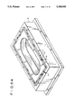
- FIG. 1 is a perspective view of a bathtub shell to which a polymeric material is applied to its non-finish side during molding operations.
- FIG. 2A is a side elevational view of the shell taken along line 2A--2A of FIG. 1, illustrating inherent variations (i.e. presence of a distortion contour) in the vertical direction caused by manufacturing processes along the bottom edge of the upper flange of the shell.
- FIG. 2B is a side elevational view of the shell taken along line 2B--2B of FIG. 1, illustrating inherent variations due to manufacturing processes in the vertical direction along the bottom edge of the upper flange of the shell.
- FIG. 3 is a top plan view of the shell taken along lines 3--3 of FIG. 1, showing inherent variations due to manufacturing processes in the horizontal direction along the sides of the upper flange of the shell.
- FIG. 4A is a perspective view of molding apparatus used in molding processes, showing a female mold portion having a molding surface and a male molding portion having a protective surface coating, with a sanitary fixture shell interposed in between.
- FIG. 4B is an elevated side view of a molding apparatus illustrated in FIG. 4A, shown with a mold press used for closing the male mold portion down onto the female molding portion, with the sanitary fixture interposed in between under high pressures.
- FIG. 5 is a side elevational view of the molding apparatus shown in FIG. 4A with the sealing system of the invention installed but not "adjusted" to accommodate the inherent distortion contour along the bottom edge of the upper flange of the shell.
- FIG. 6A is a perspective view of the female mold unit showing the installation of the sealing system of the present invention in the seal groove, with a portion of the seal broken away for purpose of illustration.
- FIG. 6B is a perspective view of a female mold portion and a male mold portion, with a shell interposed in between.
- the molding apparatus approaching its closed position, and where a portion of the male mold portion, sealing system of the present invention, and shell are shown broken away.
- FIG. 6C is a perspective view of a female mold portion and a male mold portion, with sanitary fixture shell embraced in between.
- the molding apparatus is in its closed position, and a portion of the male mold portion, sealing system of the present invention, and shell are shown broken away.
- FIG. 7 is a cross-sectional elevational view of the molding apparatus and sealing system of the present invention shown in FIG. 6C, taken along line 7--7, illustrating height adjustment means for the sealing system of the present invention, and its capability of adapting to variations in shell geometry, in providing a perfect seal during molding operations.
- FIG. 8A is a cross-sectional view taken along line 8A--8A of FIG. 6B showing the shell embraced within the molding apparatus approaching its closed position, and where the adjustable shims of the present invention are installed within the female mold portion.
- FIG. 8B is a cross-sectional view of the molding apparatus illustrated FIG. 6B taken along line 8B--8B, showing the shell embraced within the molding apparatus in its closed position, with the sealing system including the adjustable shims of the present invention in the female mold portion.
- FIG. 9A is a side elevational view of a portion of one embodiment of the adjustable shims of the present invention which is threadably adjustable.
- FIG. 9B is a cross-sectional side view of a portion of a female molding unit employing the threadably adjustable shims illustrated in FIG. 9A.
- FIG. 10A is a side elevational view of a portion of another embodiment of the adjustable shims of the present invention which is adjusted using sized ball bearings.
- FIG. 10B is a cross-sectional side view of a portion of a female mold portion employing the ball bearing adjustable shims illustrated in FIG. 10A.
- FIG. 11A is a side elevational view of a portion of yet another embodiment of the adjustable shims of the present invention which is fluid adjustable.
- FIG. 11B is a cross-sectional view of a portion of a female mold portion employing the fluid adjustable shims illustrated in FIG. 11A.
- the adjustable shims of the present invention are applicable between a wide variety of apparatus used in applying a polymeric layer to surface of a shell, such as those used in forming sanitary fixtures including bathtubs, sinks, whirlpool tubs, spas, therapeutic tubs and the like. However, for purpose of illustration, the general concepts and principles of the present invention are described and shown in apparatus for the injection molding of polymeric material to a side of a bathtub shell.
- FIG. 4A a molding apparatus used in molding polymeric layer to the non-finish surface of a shell 1, as described for example in copending U.S. patent application No. 458,598 to Marsilio et al., filed on Dec. 29, 1989, now U.S. Pat No. 5,129,804 incorporated by reference herein.
- the molding apparatus comprises a female mold portion 6 and a male mold portion 7.
- the female mold portion includes a molding surface 8 generally corresponding to the surface geometry of the underside surfaces of the shell 1 to which the polymeric coating is to be applied.
- the seal groove 9 extends about the perimeter of the molding surface 8 and extends continuously and encloses upon itself to form a groove in the shape of a substantially rectangular loop.
- the female mold portion 6 is provided with at least one aperture formed in the molding surface 8, which communicates with a mix head 20 for introducing a hardenable polymeric material into the molding cavity created between the molding surface 8 and the exterior underside surface 4 of the shell 1.
- a plurality of ejectors (not shown) positioned in the female mold portion 6, and serve to separate and eject a molded bathtub from the female mold portion 6 after the RIM or RRIM molding process has been completed.
- the ejectors are cylindrical rods which are hydraulically activated from a recessed position, to an ejector position, and vice versa.
- the male mold portion 7 comprises a pressure applying surface 11 having a surface geometry generally corresponding to the finish surface 21 of the bathtub shell 1.
- This pressure applying surface 11 bears the protective coating 12 formed from urethane material supplied to the pressure applying surface 11, in a manner described in the description of the Related Prior Art.
- This urethane protective coating 12 provides a soft resilient surface which applies pressure to the shell during molding operations, without damaging the finish surface 21 of the shell.
- the mold press 15 also includes a hydraulically operated system 16 which lowers and retains the male mold portion 7 against the finish side 21 of the bathtub shell 1 and the non-finish side 22 of the shell 1 adjacent the molding surface 8 of the female molding portion 6 during the molding process. In such a lowered position, molding cavity 18 is formed between the underside surface of the shell and the molding surface of the female portion 6, as illustrated for example in FIG. 8B in particular.
- a mold press 16 which is suitable for molding bathtubs in accordance with the method and apparatus of the present invention, is manufactured by Linden Industries, Inc.
- the female mold portion 6 is shown with the sealing system 17 installed within seal groove 9.
- the sealing system 17 comprises, in general, a seal 23 and a seal high adjustment means 19 which is disposed at the bottom 20 of the seal groove underneath the seal 23.
- the seal right adjustment means provides a desired degree of adjustment to the height of the seal above the seal groove, in a manner which will be described in greater detail below.
- the seal groove 9 comprises bottom wall 24 and opposing side walls 25 to forming a substantially rectangular shaped channel groove.
- the seal 23 has a substantially rectangular cross section, however it also has a pair of side flanges 22 which are retained within recessed wall grooves 27 formed in and along opposing side walls 25. Seals useful in the present invention are described in greater detail in copending patent application Ser. No. 07/467,771 filed Jan. 19, 1990 and abandoned and refiled as Ser. No. 931,436, entitled “ELASTOMERIC MOLD SEALS" by the inventors herein, filed concurrently herewith.
- flanges 26 of the seal are free to move in an upward and downward position within the side wall grooves 27, delimiting the maximum height adjustment of the seal within the groove 9.
- Wall grooves 27 also serve to retain the seal in the seal groove during demolding operations when the male mold portion 7 is pulled away from the female mold portion 6.
- This seal retention feature is important, since the upper flange edge 2 and cured polymeric material typically adhere to the top surface 28 of the seal 23 during demolding operations. The adherence of the seal to the shell and polymeric material would pull the seal out and away from the seal groove 9 if the seal retention feature were not present.
- removal of the seal from groove 9 would typically occur during demolding operations, requiring that the seal be manually reinserted into the groove, which is time consuming, laborious and costly from a manufacturing point of view.
- FIG. 5 there is shown a typical bathtub shell 1 which is positioned over the pressure transferring surface 11 of the male mold portion 7, which is not closed down upon the female mold portion 6.
- the seal height adjustment means 19 is not “adjusted” along the length of the seal groove, the seal would typically permit cross-seal leakage of polymeric material during high pressure molding operations. If pressure on the male mold portion 6 were increased to compensate for the leakage, the shell 1 may be damaged.
- the top surface 28 of the seal 23 is substantially parallel with the planar deck portion 10 of the female mold portion 6 and, without the seal height adjustment system properly adjusted, a substantial gap, from about 0 (or flat) to about 0.125 inches is typically formed between the upper flange bottom edge 2B and the top surface 28 of the seal 23 when the male mold portion 7 is closed down upon the female mold portion during molding operations.
- the occurrence of such a gap between the upper flange bottom edge 2B and the top surface 28 of the seal proposes serious problems, (i.e. cross seal leakage during molding operations) but is eliminated by properly adjusting height contour of the seal according to the present invention.
- FIGS. 9A and 9B, 10A and 10B, and 11A and 11B there are shown various embodiments of the height adjustment means 19 of the present invention, which can be used to adjust the height of the seal along the seal groove so that the top surface 28 of the seal will accommodate the distortion contour along the particular shell when the male mold portion 7 is closed down upon the female mold portion 6 during molding operations.
- solid is intended to refer to a portion of the seal member which is non-inflatable as shown in the embodiment of the invention illustrated in FIGS. 9A and 10A.
- the seal height adjustment means 19 comprises one or more structural elements 35, each including a first planar member 36 disposed on the bottom surface 24 of the seal groove 9, and a second member 37 disposed above the first member 36 and adapted for supporting the seal 23.
- Each structural element 35 also includes a plurality of adjustable separation elements 38 which are vertically disposed along the length of the first and second planar members, and pass through at least a portion of the first and second members 36, 37. These adjustable separation elements 38 are capable of providing variable spacing between and along respective portions of the first and second planar members 36, 37.
- each separation element 38 comprises a screw which passes through a pair of vertically aligned threaded holes 39A and 39B formed through the first and second planar members 36 and 37, respectively.
- the threaded holes receive selected portions of the screws so as to establish a preselected height adjustment contour between and along the first and second planar members 36, 37.
- the structural element 35 is disposed along the bottom 24 of the seal groove 9, and under the seal 23.
- FIGS. 10A and 10B another preferred embodiment of the seal height adjustment means of the present invention is shown.
- the seal height adjustment means 19 is realized by a structural element 35A, comprising a first planar member 36A which is disposed on the bottom surface 24 of the seal groove 9, and a second planer member 37A which is disposed above the first planar member 36A, provides support for the seal 23.
- a plurality of separation elements 38A in the form of spherical ball bearings 38A are received in respective concave indentations 39A formed on the first planer member 36A, to provide a predetermined spacing between and along respective portions of the first and second members 36A and 37A, respectively.
- Each ball bearing 38A has a diameter selected to provide the desired spacing between the first and second members along the length of the structural element 35A and establishes a preselected height adjustment contour of the seal.
- the seal height adjustment means in accordance with this embodiment is realized by a structural element 45 comprising a tubular structure 46.
- the tubular structure 46 has a length dimension sufficient to extend along the length of the seal groove 9.
- the tubular structure 46 has an expandable cross-sectional dimension which is capable of receiving a selected volume of air or other fluid to support, under pressure, the seal 23 at various heights above the seal groove 9, when the molding apparatus is closed during molding operations.
- the ends of the tubular structure 45 are sealed, and the side walls 47 are elastic in nature so as to expand when the tubular structure is filled with fluids, such as air under a desirable range of pressure.
- the cross-sectional geometry of the tubular structure 45 may vary from embodiment to embodiment, and preferably is provided with a planer base 47 which is adapted to lie flat within the bottom 20 of the seal groove 9.
- the tubular structure 46 have a planar support flange 46 extending along the length of the tubular structure 45, in order to provide support and apply pressure to the bottom portion of the seal when installed within the groove as illustrated in FIG. 11B.
- the base flange 47 and support flange 48 may be typically formed from the same flexible material as is side walls 46, but are relatively thick in comparison, to provide the desired support to the seal.
- tubular structural element 45 can be manufactured using known plastic extrusion technology, inflatable pneumatic gaskets are available from Spray Corporation, Pawling, N.Y., sold under the Trademark PNEUMA-SEAL, and can be employed in the present invention.
- the seal 23 is elevated in height so as to snuggly fit against adjacent portions of the bottom edges of the flange edges 2 of the bathtub shell 1, forming a complete seal free from cross-seal leakage.
- the tubular structure element 45 automatically establishes a preselected height adjustment contour along the bottom portion of the seal, thereby causing the top portion of the seal to adapt to a surface geometry of the "distortion contour" of the upper flange edges 2 of the bathtub shell.
- the height adjustment means 19 may comprise a shim as illustrated in FIGS. 8A and 8B.
- the shim may extend along the bottom of the seal groove 9 and the upper surface 50 of the shim may be shaped to the desired contour.
- the shim may be composed from a variety of materials, including woods, metals, plastics and polymers.
- the shim is preferably solid and shaped using known sanding techniques.
Abstract
Description
Claims (15)
Priority Applications (6)
| Application Number | Priority Date | Filing Date | Title |
|---|---|---|---|
| US07/467,184 US5208043A (en) | 1990-01-19 | 1990-01-19 | Adjustable shims for mold seals |
| ES90907921T ES2082857T3 (en) | 1990-01-19 | 1990-03-21 | ADJUSTABLE SHOES FOR MOLDING JOINTS. |
| DE69024664T DE69024664T2 (en) | 1990-01-19 | 1990-03-21 | ADJUSTABLE INLETS FOR MOLDED SEALS |
| AU55357/90A AU5535790A (en) | 1990-01-19 | 1990-03-21 | Adjustable shims for mold seals |
| PCT/US1990/001539 WO1991010548A1 (en) | 1990-01-19 | 1990-03-21 | Adjustable shims for mold seals |
| EP90907921A EP0509990B1 (en) | 1990-01-19 | 1990-03-21 | Adjustable shims for mold seals |
Applications Claiming Priority (1)
| Application Number | Priority Date | Filing Date | Title |
|---|---|---|---|
| US07/467,184 US5208043A (en) | 1990-01-19 | 1990-01-19 | Adjustable shims for mold seals |
Publications (1)
| Publication Number | Publication Date |
|---|---|
| US5208043A true US5208043A (en) | 1993-05-04 |
Family
ID=23854714
Family Applications (1)
| Application Number | Title | Priority Date | Filing Date |
|---|---|---|---|
| US07/467,184 Expired - Lifetime US5208043A (en) | 1990-01-19 | 1990-01-19 | Adjustable shims for mold seals |
Country Status (6)
| Country | Link |
|---|---|
| US (1) | US5208043A (en) |
| EP (1) | EP0509990B1 (en) |
| AU (1) | AU5535790A (en) |
| DE (1) | DE69024664T2 (en) |
| ES (1) | ES2082857T3 (en) |
| WO (1) | WO1991010548A1 (en) |
Cited By (11)
| Publication number | Priority date | Publication date | Assignee | Title |
|---|---|---|---|---|
| US5330339A (en) * | 1990-01-19 | 1994-07-19 | American Standard Inc. | Molding apparatus |
| US5362072A (en) * | 1992-12-21 | 1994-11-08 | Imo Industries, Inc., Quabbin Division | Turbine radial adjustable labyrinth seal |
| US5503405A (en) * | 1991-05-07 | 1996-04-02 | General Electric Co. | Apparatus for providing uniform radial clearance of seals between rotating and stationary components |
| US5509780A (en) * | 1995-03-08 | 1996-04-23 | General Electric Co. | Apparatus and method for providing uniform radial clearance of seals between rotating and stationary components |
| US5643612A (en) * | 1994-06-07 | 1997-07-01 | Kabushiki Kaisha Inoac Corporation | Partial pad mold |
| US5676381A (en) * | 1990-09-17 | 1997-10-14 | Industrie Ilpea S.P.A. - Malgesso | Gasket and apparatus used in slush mold |
| CN1319713C (en) * | 2003-07-24 | 2007-06-06 | Ykk株式会社 | Foam bun mold shim |
| US20070254139A1 (en) * | 2004-11-23 | 2007-11-01 | Webasto Ag | Device for Foam-Coating and/or Spraying a Substantially Flat Workpiece |
| US11260736B1 (en) * | 2017-08-10 | 2022-03-01 | Magna Mirrors Of America, Inc. | System for molding encapsulation at glass window panel |
| US20220354309A1 (en) * | 2021-05-10 | 2022-11-10 | Simeaco Williams | Corn Dog Mold Device |
| US20230184241A1 (en) * | 2021-12-14 | 2023-06-15 | Gd Energy Products, Llc | Sealing assembly with repositionable seal |
Families Citing this family (1)
| Publication number | Priority date | Publication date | Assignee | Title |
|---|---|---|---|---|
| FI122782B (en) * | 2008-08-12 | 2012-06-29 | Stora Enso Oyj | A mold system and method for making a board-based container |
Citations (14)
| Publication number | Priority date | Publication date | Assignee | Title |
|---|---|---|---|---|
| US2480055A (en) * | 1946-02-07 | 1949-08-23 | Alex J Seaton | Stuffing box construction |
| US2760749A (en) * | 1951-01-11 | 1956-08-28 | J P Ratigan Inc | Composite block for shut-off mechanism |
| US2841823A (en) * | 1954-02-08 | 1958-07-08 | Carroll H Van Hartesveldt | Molding apparatus |
| US3486772A (en) * | 1966-12-05 | 1969-12-30 | Aeroquip Corp | Fluid coupling with deformable holding means |
| US4362304A (en) * | 1979-11-28 | 1982-12-07 | Huenger Walter | Packing arrangement for a floating piston |
| US4394022A (en) * | 1981-09-29 | 1983-07-19 | Gilmore Richard F | Mechanically expandable annular seal |
| US4448425A (en) * | 1981-11-05 | 1984-05-15 | Howaldtswerke-Deutsche Werft Aktiengesellschaft Hamburg Und Kiel | Shaft seal assembly with inflatable annular member |
| US4626185A (en) * | 1984-09-21 | 1986-12-02 | Billion S.A. | Method and apparatus for molding a frame around the periphery of a flat or curved object |
| US4664982A (en) * | 1983-07-15 | 1987-05-12 | American Standard Inc. | Multi-layer composite structure |
| US4732553A (en) * | 1987-07-06 | 1988-03-22 | Libbey-Owens-Ford Co. | Seal construction for a mold structure for encapsulating glass with a gasket |
| US4776261A (en) * | 1987-05-08 | 1988-10-11 | Larson John W | Reciprocating engine piston seal |
| US4844944A (en) * | 1987-12-18 | 1989-07-04 | American Standard, Inc. | Lightweight, durable plumbing fixture fabricated from a delamination-resistant multilayer polymeric composite |
| US4844955A (en) * | 1987-12-18 | 1989-07-04 | American Standard, Inc. | Multilayer polymeric composite and method for its manufacture |
| US4915395A (en) * | 1987-08-21 | 1990-04-10 | Libbey-Owens-Ford Co. | Seal construction for a mold structure for encapsulating glass with a gasket |
Family Cites Families (3)
| Publication number | Priority date | Publication date | Assignee | Title |
|---|---|---|---|---|
| FR2546812B1 (en) * | 1983-05-30 | 1986-04-18 | Saint Gobain Vitrage | |
| EP0259449A1 (en) * | 1986-02-20 | 1988-03-16 | Libbey-Owens-Ford Co. | Seal construction for a mold structure for encapsulating glass with a gasket |
| US4854599A (en) * | 1987-08-21 | 1989-08-08 | Libbey-Owens-Ford Co. | Seal construction for a mold structure for encapsulating glass with a gasket |
-
1990
- 1990-01-19 US US07/467,184 patent/US5208043A/en not_active Expired - Lifetime
- 1990-03-21 ES ES90907921T patent/ES2082857T3/en not_active Expired - Lifetime
- 1990-03-21 EP EP90907921A patent/EP0509990B1/en not_active Expired - Lifetime
- 1990-03-21 DE DE69024664T patent/DE69024664T2/en not_active Expired - Lifetime
- 1990-03-21 AU AU55357/90A patent/AU5535790A/en not_active Abandoned
- 1990-03-21 WO PCT/US1990/001539 patent/WO1991010548A1/en active IP Right Grant
Patent Citations (14)
| Publication number | Priority date | Publication date | Assignee | Title |
|---|---|---|---|---|
| US2480055A (en) * | 1946-02-07 | 1949-08-23 | Alex J Seaton | Stuffing box construction |
| US2760749A (en) * | 1951-01-11 | 1956-08-28 | J P Ratigan Inc | Composite block for shut-off mechanism |
| US2841823A (en) * | 1954-02-08 | 1958-07-08 | Carroll H Van Hartesveldt | Molding apparatus |
| US3486772A (en) * | 1966-12-05 | 1969-12-30 | Aeroquip Corp | Fluid coupling with deformable holding means |
| US4362304A (en) * | 1979-11-28 | 1982-12-07 | Huenger Walter | Packing arrangement for a floating piston |
| US4394022A (en) * | 1981-09-29 | 1983-07-19 | Gilmore Richard F | Mechanically expandable annular seal |
| US4448425A (en) * | 1981-11-05 | 1984-05-15 | Howaldtswerke-Deutsche Werft Aktiengesellschaft Hamburg Und Kiel | Shaft seal assembly with inflatable annular member |
| US4664982A (en) * | 1983-07-15 | 1987-05-12 | American Standard Inc. | Multi-layer composite structure |
| US4626185A (en) * | 1984-09-21 | 1986-12-02 | Billion S.A. | Method and apparatus for molding a frame around the periphery of a flat or curved object |
| US4776261A (en) * | 1987-05-08 | 1988-10-11 | Larson John W | Reciprocating engine piston seal |
| US4732553A (en) * | 1987-07-06 | 1988-03-22 | Libbey-Owens-Ford Co. | Seal construction for a mold structure for encapsulating glass with a gasket |
| US4915395A (en) * | 1987-08-21 | 1990-04-10 | Libbey-Owens-Ford Co. | Seal construction for a mold structure for encapsulating glass with a gasket |
| US4844944A (en) * | 1987-12-18 | 1989-07-04 | American Standard, Inc. | Lightweight, durable plumbing fixture fabricated from a delamination-resistant multilayer polymeric composite |
| US4844955A (en) * | 1987-12-18 | 1989-07-04 | American Standard, Inc. | Multilayer polymeric composite and method for its manufacture |
Cited By (11)
| Publication number | Priority date | Publication date | Assignee | Title |
|---|---|---|---|---|
| US5330339A (en) * | 1990-01-19 | 1994-07-19 | American Standard Inc. | Molding apparatus |
| US5676381A (en) * | 1990-09-17 | 1997-10-14 | Industrie Ilpea S.P.A. - Malgesso | Gasket and apparatus used in slush mold |
| US5503405A (en) * | 1991-05-07 | 1996-04-02 | General Electric Co. | Apparatus for providing uniform radial clearance of seals between rotating and stationary components |
| US5362072A (en) * | 1992-12-21 | 1994-11-08 | Imo Industries, Inc., Quabbin Division | Turbine radial adjustable labyrinth seal |
| US5643612A (en) * | 1994-06-07 | 1997-07-01 | Kabushiki Kaisha Inoac Corporation | Partial pad mold |
| US5509780A (en) * | 1995-03-08 | 1996-04-23 | General Electric Co. | Apparatus and method for providing uniform radial clearance of seals between rotating and stationary components |
| CN1319713C (en) * | 2003-07-24 | 2007-06-06 | Ykk株式会社 | Foam bun mold shim |
| US20070254139A1 (en) * | 2004-11-23 | 2007-11-01 | Webasto Ag | Device for Foam-Coating and/or Spraying a Substantially Flat Workpiece |
| US11260736B1 (en) * | 2017-08-10 | 2022-03-01 | Magna Mirrors Of America, Inc. | System for molding encapsulation at glass window panel |
| US20220354309A1 (en) * | 2021-05-10 | 2022-11-10 | Simeaco Williams | Corn Dog Mold Device |
| US20230184241A1 (en) * | 2021-12-14 | 2023-06-15 | Gd Energy Products, Llc | Sealing assembly with repositionable seal |
Also Published As
| Publication number | Publication date |
|---|---|
| WO1991010548A1 (en) | 1991-07-25 |
| DE69024664D1 (en) | 1996-02-15 |
| DE69024664T2 (en) | 1996-08-14 |
| ES2082857T3 (en) | 1996-04-01 |
| AU5535790A (en) | 1991-08-05 |
| EP0509990B1 (en) | 1996-01-03 |
| EP0509990A1 (en) | 1992-10-28 |
Similar Documents
| Publication | Publication Date | Title |
|---|---|---|
| US5208043A (en) | Adjustable shims for mold seals | |
| KR950000175B1 (en) | Vacuum compression molding method for using preheated charge | |
| KR950008553B1 (en) | Mold structure for window assembly | |
| CA1217017A (en) | Compression molding apparatus having vacuum chamber | |
| US4668460A (en) | Method of molding and coating a substrate in a mold. | |
| US4909875A (en) | Method for obtaining multiple glazing and device for using said method | |
| JPH0247350B2 (en) | ||
| US5119518A (en) | Sanitary fixture having an extended deck with a coating of variable thickness | |
| US3339239A (en) | Injection molding apparatus with diaphragm valve | |
| US5119535A (en) | Method of reconfiguring rigid and semirigid structures | |
| US5206076A (en) | Elastomeric mold seals | |
| JPH04305212A (en) | Method and device for manufacturing air filter for automobile engine and air filter manufactured through said method | |
| US5200257A (en) | Elastomeric mold seals | |
| US2929109A (en) | Method for molding pulverulent material | |
| US20030183985A1 (en) | Ceramic casting apparatus and method | |
| US4519567A (en) | Mold for manufacturing an annular object of elastic material | |
| EP0511206B1 (en) | Elastomeric mold seals | |
| JP3992463B2 (en) | Tire vulcanizer | |
| US4349326A (en) | Apparatus for manufacturing articles by pressing and sintering | |
| JPH0284311A (en) | High-frequency molding method and device for liquefied plastic material | |
| US5098629A (en) | Method of manufacturing bathtubs and the like using molding apparatus and resilient insert | |
| US5083913A (en) | Mix head bushing seal | |
| US4470803A (en) | Method and apparatus for manufacturing articles by pressing and sintering | |
| US5230108A (en) | Molded articles | |
| JPH0436893Y2 (en) |
Legal Events
| Date | Code | Title | Description |
|---|---|---|---|
| AS | Assignment |
Owner name: AMERICAN STANDARD INC., NEW YORK Free format text: ASSIGNMENT OF ASSIGNORS INTEREST.;ASSIGNOR:MARSILIO, RONALD M.;REEL/FRAME:005226/0726 Effective date: 19900118 Owner name: AMERICAN STANDARD INC., NEW YORK Free format text: ASSIGNMENT OF ASSIGNORS INTEREST.;ASSIGNOR:GATARZ, GREGORY M.;REEL/FRAME:005226/0723 Effective date: 19900118 |
|
| AS | Assignment |
Owner name: AMERICAN STANDARD INC., NEW YORK Free format text: ASSIGNMENT OF ASSIGNORS INTEREST.;ASSIGNORS:GATARZ, GREGORY M.;MARSILIO, RONALD M.;REEL/FRAME:005250/0813 Effective date: 19900216 |
|
| STCF | Information on status: patent grant |
Free format text: PATENTED CASE |
|
| AS | Assignment |
Owner name: CHEMICAL BANK, AS COLLATERAL AGENT, NEW YORK Free format text: ASSIGNMENT OF ASSIGNORS INTEREST;ASSIGNOR:AMERICAN STANDARD INC.;REEL/FRAME:006566/0170 Effective date: 19930601 |
|
| FEPP | Fee payment procedure |
Free format text: PAYOR NUMBER ASSIGNED (ORIGINAL EVENT CODE: ASPN); ENTITY STATUS OF PATENT OWNER: LARGE ENTITY |
|
| FPAY | Fee payment |
Year of fee payment: 4 |
|
| AS | Assignment |
Owner name: AMERICAN STANDARD, INC., NEW JERSEY Free format text: RELEASE OF SECURITY INTEREST (RE-RECORD TO CORRECT DUPLICATES SUBMITTED BY CUSTOMER. THE NEW SCHEDULE CHANGES THE TOTAL NUMBER OF PROPERTY NUMBERS INVOLVED FROM 1133 TO 794. THIS RELEASE OF SECURITY INTEREST WAS PREVIOUSLY RECORDED AT REEL 8869, FRAME 0001.);ASSIGNOR:CHASE MANHATTAN BANK, THE (FORMERLY KNOWN AS CHEMICAL BANK);REEL/FRAME:009123/0300 Effective date: 19970801 |
|
| AS | Assignment |
Owner name: AMERICAN STANDARD, INC., NEW JERSEY Free format text: RELEASE OF SECURITY INTEREST;ASSIGNOR:CHASE MANHATTAN BANK, THE (FORMERLY KNOWN AS CHEMICAL BANK);REEL/FRAME:008869/0001 Effective date: 19970801 |
|
| FPAY | Fee payment |
Year of fee payment: 8 |
|
| REMI | Maintenance fee reminder mailed | ||
| FPAY | Fee payment |
Year of fee payment: 12 |
|
| SULP | Surcharge for late payment |
Year of fee payment: 11 |
|
| AS | Assignment |
Owner name: IDEAL STANDARD GLOBAL LTD., UNITED KINGDOM Free format text: ASSIGNMENT OF ASSIGNORS INTEREST;ASSIGNOR:AMERICAN STANDARD INC.;REEL/FRAME:022092/0592 Effective date: 20071031 |