US5202637A - Fault detection in electrochemical gas sensing equipment - Google Patents
Fault detection in electrochemical gas sensing equipment Download PDFInfo
- Publication number
- US5202637A US5202637A US07/761,976 US76197691A US5202637A US 5202637 A US5202637 A US 5202637A US 76197691 A US76197691 A US 76197691A US 5202637 A US5202637 A US 5202637A
- Authority
- US
- United States
- Prior art keywords
- potential
- monitor
- sensor
- electrode
- gas
- Prior art date
- Legal status (The legal status is an assumption and is not a legal conclusion. Google has not performed a legal analysis and makes no representation as to the accuracy of the status listed.)
- Expired - Lifetime
Links
Images


Classifications
-
- G—PHYSICS
- G01—MEASURING; TESTING
- G01N—INVESTIGATING OR ANALYSING MATERIALS BY DETERMINING THEIR CHEMICAL OR PHYSICAL PROPERTIES
- G01N27/00—Investigating or analysing materials by the use of electric, electrochemical, or magnetic means
- G01N27/26—Investigating or analysing materials by the use of electric, electrochemical, or magnetic means by investigating electrochemical variables; by using electrolysis or electrophoresis
- G01N27/403—Cells and electrode assemblies
- G01N27/404—Cells with anode, cathode and cell electrolyte on the same side of a permeable membrane which separates them from the sample fluid, e.g. Clark-type oxygen sensors
-
- G—PHYSICS
- G01—MEASURING; TESTING
- G01N—INVESTIGATING OR ANALYSING MATERIALS BY DETERMINING THEIR CHEMICAL OR PHYSICAL PROPERTIES
- G01N33/00—Investigating or analysing materials by specific methods not covered by groups G01N1/00 - G01N31/00
- G01N33/0004—Gaseous mixtures, e.g. polluted air
- G01N33/0009—General constructional details of gas analysers, e.g. portable test equipment
- G01N33/007—Arrangements to check the analyser
Definitions
- the present invention relates to a gas monitor incorporating one or more amperometric gas sensors and in particular it relates to improvements in the electronic circuits of the monitors allowing the monitor to test that the sensor is working properly.
- Gas monitors are known that include one or more replaceable amperometric gas sensors providing an electrical current the magnitude of which provides a measure of the amount of gas detected in an atmosphere.
- This signal is analysed by circuitry within the monitor to give a monitor output which may be in the form of a display (in an analogue or digital form) of the amount of a specific gas detected and/or the output may be a printer or plotter and/or an alarm to give an audible and/or visual warning if the concentration of a gas falls to an undesirable level or if the concentration of a gas arises above a certain threshold level; the output signal could be recorded for subsequent analysis.
- the gas monitor need not necessarily give a direct indication of the amount of gas detected but may use the signal from one or more sensors to compute another parameter which may be displayed or printed; thus, the signal from a gas sensor may be used, together with other measurements, to compute the efficiency of a boiler (see British Patent No. 2,064,780).
- the sensors used in the monitors of the present invention are amperometric electrochemical sensors of the type having a sensing (or working) electrode which is in communication with the atmosphere being sensed, a counter electrode and a reference electrode and all three electrodes are in contact with electrolyte within the sensor and are connected via respective terminals to the circuitry within the monitor; sensors of this type will be eferred to herein as "three electrode sensors”.
- the potential difference between the sensing electrode and the reference electrode may be controlled and in some sensors this is done by connecting these two electrodes to the inputs of an operational amplifier either directly or through a resistor, e.g. see British Patent Specification Nos. 1,101,101 and 1,385,201 and U.S. Pat. No. 3,776,832 and European Patent Application No. 0,220,896A.
- FIG. 1 A circuit generally in accordance with the above patents is set out in FIG. 1 of the accompanying drawings.
- the sensor is indicated by the general reference number 10 and includes an electrolyte (sulphuric acid), a sensing electrode 12, a reference electrode 14 and a counter electrode 16 all of which are in contact with the electrolyte.
- the sensing electrode and the reference electrode are joined via terminals 12a and 14a to respective inputs of an operational amplifier 18 whose output is connected to the counter electrode 16 via terminal 16a.
- a resistor 20 is present between the sensing electrode 12 and its input to the operational amplifier 18.
- the sensing electrode 12 is in contact with an atmosphere that is being monitored and when the atmosphere contains a gas of the type being detected, this gas undergoes an electrochemical reaction which depolarizes the sensing electrode 12 causing the potential of that electrode to alter and so cause an imbalance between the potential of the sensing electrode 12 and the reference electrode 14 and hence between the inputs of the operational amplifier 18.
- the potential difference between the operational amplifier inputs causes the operational amplifier to supply current through its output to counter electrode 16 and hence causes a current to flow in the sensor cell 10 between the counter electrode 16 and the sensing electrode 12 (however substantially no current flows between the reference electrode and the sensing electrode).
- the current flowing through the sensor cell which is directly related to the amount of gas in the atmosphere, can be measured, for example, by including a resistor between the amplifier output and the counter electrode 16 and measuring the voltage drop across the resistor (see U.S. Pat. No. 3,776,832); alternatively, the current flowing through the cell may be measured by a current follower connected to line 22 or by measuring the potential difference across a resistor between line 22 and a ground or other fixed potential (see European Patent Application No. 0,220,896); alternatively, the voltage drop across the resistor 20 may be measured (see British Patent No. 1,101,101).
- Resistor 20 is included between the sensing electrode and the operational amplifier in order to slow the response time of the sensor and thus provide immunity from electronic noise and fluctuations in the potential of the sensing electrode; the value of resistor 20 is generally chosen between 0 and 500 ohms.
- the amplifier 18 has an offset null potentiometer 19 which is usually set such that current is supplied by the amplifier to its output unless there is no potential difference between the two inputs of the amplifier; however, the offset null can be set to provide an offset voltage between the amplifier inputs, in which case current is supplied by the amplifier to its output unless the potential between the amplifier inputs is a certain, non-zero value (the offset voltage).
- the amplifier When an offset voltage is set, the amplifier will supply current to its output and to the sensor until a potential difference is created between its inputs that equals the offset voltage and when this occurs, there is a potential difference between the sensing electrode and the electrolyte immediately surrounding it; the presence of a layer of electrolyte around an electrode that is at a different potential to the electrode is termed a ⁇ double layer ⁇ and acts like a capacitor.
- a substantial voltage offset is maintained between the sensing and reference electrodes in order to minimise cross-sensitivity with gases other than the gas that it is desired to detect which may be present in the atmosphere being monitored and such an arrangement is used in particular to minimise cross-sensitivity to hydrogen gas; however when a large offset is established between the sensing and the reference electrode, it can take 2 days for a sensor to settle to a steady state when the monitor is first switched on (and no accurate readings can be taken during this period) and such monitors are normally kept permanently switched on to avoid this problem.
- the monitor will show a zero reading, even if there is gas in the atmosphere being detected and the user will assume that the atmosphere contains no gas of the type being monitored. Since monitors can detect poisonous gases, e.g. carbon monoxide, this can be dangerous. Thus, the circuit of the above type is not ⁇ fail-safe ⁇ . A further problem can arise if the electrolyte of the sensor cell 10 evaporates so that the cell dries out and no longer conducts electric current; in this case, a zero reading is again obtained even if there is gas in the atmosphere being monitored.
- CH-636 447 It has been proposed in CH-636 447 to check that a pH reference (or counter) electrode is operating properly in a potentiometric titration apparatus by measuring the resistance between the counter and the sensing electrodes of the titration apparatus by passing an alternating current between these electrodes, rectifying the resulting current, passing an identical alternating current through a fixed resistor, rectifying the resulting current and subtracting the two rectified currents from each other to form a signal and stopping the titration if the said signal indicates that the resistance between the sensing electrode and the counter electrode is either much higher or much lower than the resistance of the fixed resistor.
- CH-636 447 uses potential as a sensing criterion rather current as is the case with the present invention
- the proposal in CH-636 447 is complex and hence expensive to implement.
- EP 0 039 549 describes a system for testing the operation of electrochemical gas sensors having a salt solution electrolyte by applying a pulse of potential between the electrodes of the sensor that decomposes the electrolyte; if there is a resulting change in current flowing through the sensor, then the sensor is operating properly.
- the electrolysis of the electrolyte causes gas to be generated, which is disadvantageous in a sealed gas sensor since it can affect the sensor operation and pressure can build up within the sensor causing it to leak; the present provides a system that avoids these problems.
- the present invention is based on the concept that the potential across the double layer at the sensing electrode of a three electrode sensor cannot be changed instantaneously because of the large capacitance of the double layer and the resistance of the rest of the circuit. If the potential between the reference electrode and the sensing electrode is changed, a current will flow until the double layer capacitance is charged to a new potential and this flow of current can be detected and used to confirm that the sensor is working properly; if, however, the sensor is not working properly (or is absent), a reduced current (or no current) will flow as a result of the potential being imposed and this reduced (or non-existent) current can be used to provide a warning that the sensor is not working properly.
- One advantage of the present invention is that, providing the imposed potential is applied only for a short time, the double layer reverts to its operational potential when the imposed potential is removed within a very short time (a fraction of a millisecond) and normal operation of the sensor can then be continued and so the time that the sensor is not operating to monitor the atmosphere is minimal. It is not necessary for the double layer to be completely charged in the operation of the present invention and indeed the partial charging of the double layer is preferred.
- a gas monitor for detecting the presence of a certain gas in an atmosphere being monitored which monitor comprises:
- an amperometric electrochemical gas sensor comprising electrolyte and a sensing electrode, a reference electrode and a counter electrode, all in contact with the electrolyte;
- the means for maintaining the first potential (or average potential) is preferably an operational amplifier having inputs connected directly or indirectly to the sensing- and reference-electrodes and an output connected either to the counter electrode or to the sensing electrode.
- the first potential (or average potential) is preferably zero.
- the pulses of second potential between the reference electrode and the sensing electrode may be impressed in several ways, for example:
- the balance of the operational amplifier may be disturbed so that the amplifier produces an output for a short time, e.g. the offset null of the operational amplifier may be disturbed so that the amplifier produces an offset voltage (or a different offset voltage), or
- a voltage may be impressed between the two electrodes from a voltage source, which usually will be the power source of the monitor; the voltage may be a short-lived pulse or a fluctuating voltage, e.g. an alternating voltage, that is continuously or periodically impressed between the two electrodes. If the voltage source provides a fluctuating voltage, the period of the fluctuations should preferably be shorter than the response time of the monitor output (i.e.
- the device measuring the current flowing through the sensor cell and giving an indication of the amount of the gas being monitored in the atmosphere) so that the output signal of the monitor in the presence of the gas to be detected will not be influenced by the imposed voltage; likewise the period of the fluctuations is preferably longer than the response time of the device for detecting the current resulting from the imposition of the second voltage. Furthermore, it is preferred that the fluctuating voltage should average out to zero so that the reading produced by the sensor in the presence of the gas to be detected is not affected by the imposed fluctuating voltage.
- the said first potential between the sensing- and the reference-electrodes will be the average voltage of the imposed voltage whereas the second voltage will be the peak (or trough) of the alternating voltage.
- a method of testing the operation of an amperometric electrochemical sensor in a gas monitor comprising:
- the imposition of the second potential between the reference electrode and the sensing electrode causes a current to flow in the sensor which charges the double layer at the sensing electrode. While the double layer is being charged, a substantial current can flow through the sensor and the external circuit and this current decays as the double layer is charged. The rate at which the double layer is charged depends on the resistance in the external circuit in the monitor and in particular on the resistance between the sensing electrode and its corresponding input into the operational amplifier. The current that flows while the double layer is being charged can be detected relatively easily by a device within the monitor. Hitherto, there has been no proposal to use such an offset current to provide confirmation that the sensor is working.
- the sensor monitoring system of the present invention measures the capacitance of the double layer at the sensing electrode, whereas the device of CH-636 447 measures the resistance of the electrolyte between the sensing and reference electrodes.
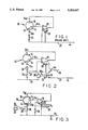
- FIG. 1 is a known circuit for a gas monitor
- FIGS. 2 to 7 are gas monitor circuits of the present invention.
- the circuit shown in FIG. 2 is identical to that of FIG. 1 with two exceptions: the first difference lies in that the current flowing through the sensor is detected across a high value resistor 24 connected between a fixed voltage line 26 and a further line 28 by means of a high impedance potentiometer 30.
- the current flowing through resistor 24 is the same as that flowing through the sensor cell because the impedance between the inputs of the amplifier 18 is large and because the potentiometer 30 is of high impedence; by making the value of resistor 24 large (e.g. 10 kohms) the voltage drop across resistor 24 is large and this can be used directly (i.e. without further amplification) to drive an output device 31, which can be, for example, a voltmeter or a display.
- the second difference lies in the connection of the offset null 19 to an earth line 32 via a transistor 34.
- the transistor is non-conductive but a pulse may be supplied along control line 35 which renders the transistor conducting and so connects the potentiometer 19 to the earth line, thereby upsetting the offset null and driving the amplifier 18 to provide an output current causing a current to flow through the sensor and through the resistors 20 and 24 which will charge the double layer and generate a potential difference between the sensing electrode and the reference electrode.
- the current can be detected by an alarm device 33 connected to the potentiometer 30 by a switch 30a while the sensor is being tested; the switch 30a is operated by means (not shown) to connect the potentiometer to alarm 33 for the time that the monitor is under test, i.e.
- the switch 30a is arranged to connect the potentiometer to the output device 31. If the signal from the potentiometer 30 to the alarm device 33 is less than a threshold value then the device 33 emits a visible and/or audible alarm indicating that the sensor is not working properly.
- any switching device can be used to connect the offset potentiometer 19 to the earth line 32, e.g. a field effect transistor, an integrated circuit, a relay etc.
- the pulse to the control 35 of transistor 34 can be sent when the monitor is first switched on or periodically during its operation.
- the duration of the pulse should be sufficient to allow the alarm 33 to register the current resulting from the upsetting of the offset null but is should be kept to a minimum to minimise the period in which the monitor is being tested (and hence not monitoring the atmosphere); we have found that a pulse duration of 1 to 10 milliseconds has proved satisfactory.
- the pulse to transistor 34 is supplied while the monitor is put into a test mode during which the normal output device 31 of the monitor (e.g. a display, a voltmeter or an alarm) is disconnected since otherwise the output device might give a spurious reading.
- the potentiometer 30 is, as mentioned above, connected via a switch 30a to the alarm 33.
- test routine is completed, the normal operation of the monitor is resumed by re-connecting the normal output device 31 to the potentiometer 30 by means of a switch 30a.
- a typical test routine might last approximately 1 millisecond and so the down-time for the monitor is negligible.
- the circuit shown in FIG. 3 includes a square wave generator 36 (although any other shape of wave or pulse may be used) which superimposes an oscillating potential between the sensing electrode 12 and the reference electrode 14 causing an oscillating current to flow through the sensor cell 10 which can be detected by potentiometer 30. If the average current caused to flow as a result of the oscillating potential is zero then the net output recorded by output device 31 will be unaffected by the superimposed voltage.
- Temporary fluctuations in the signal fed from the potentiometer 30 to the output device 31 could be eliminated by making the duration of each cycle of the oscillating potential shorter than the response time of the output device 31 or by placing a suitable filter or buffer between the switch 30a and the output device 31 to slow the response time of the latter.
- An additional resistor 38 is included between the potential source 36 and the sensing electrode 12 across which the oscillating voltage is impressed.
- the alarm 33 is triggered if the potentiometer indicates no current flowing for a period of time corresponding to at least one cycle of the alternating current. It will be evident that the response time of the alarm 33 should be sufficiently fast to register the fluctuations in the potential across the resistor 20 caused by the oscillating potential of the wave generator 36.
- the balance of the amplifier 18 can instead be upset by adding a signal to one of the amplifier inputs. This is achieved in the circuit shown in FIG. 4 by including a buffer amplifier 40 between the reference electrode 14 and the operational amplifier 18 and connecting the offset null 42 of the buffer amplifier to the earth line 32 via transistor 34.
- the offset null of buffer amplifier 40 is upset, thereby causing a current to be supplied by the output of buffer amplifier 40 to one of the inputs of amplifier 18 and so causing the output of amplifier 18 to provide a current to the counter electrode 16, which results in a current through the cell if it is functioning correctly and this can be detected by the alarm device 33; if the signal to the alarm device 33 from potentiometer 30 is below a threshold value, it generates an alarm.
- the current flowing through the cell is detected as a voltage drop across resistor 44 connected between the output of amplifier 18 and the counter electrode 16.
- FIG. 6 is identical to FIG. 2 except that the output of the amplifier 18 is connected to the sensing electrode 12 and the resistor 24 is connected to the counter-electrode.
- FIG. 7 is identical to FIG. 2 except that the offset null potentiometer 19 is connected to the positive voltage rail 40 of the monitor instead of the earth rail 32.
- the initiation of the test routine can be controlled by a microprocessor unit within the monitor, in which case the sensor current could be continually monitored by periodically initiating a test routine and also the switch 30a would not then be required as the microprocessor could control the output and alarm devices 31 and 33.
Abstract
Description
Claims (11)
Applications Claiming Priority (2)
| Application Number | Priority Date | Filing Date | Title |
|---|---|---|---|
| GB898907564A GB8907564D0 (en) | 1989-04-04 | 1989-04-04 | Fault detection in electrochemical gas sensing equipment |
| GB8907564 | 1989-04-04 |
Publications (1)
| Publication Number | Publication Date |
|---|---|
| US5202637A true US5202637A (en) | 1993-04-13 |
Family
ID=10654432
Family Applications (1)
| Application Number | Title | Priority Date | Filing Date |
|---|---|---|---|
| US07/761,976 Expired - Lifetime US5202637A (en) | 1989-04-04 | 1990-04-04 | Fault detection in electrochemical gas sensing equipment |
Country Status (7)
| Country | Link |
|---|---|
| US (1) | US5202637A (en) |
| EP (1) | EP0467902B1 (en) |
| JP (1) | JP2951721B2 (en) |
| CA (1) | CA2051099C (en) |
| DE (1) | DE69023129T2 (en) |
| GB (1) | GB8907564D0 (en) |
| WO (1) | WO1990012315A1 (en) |
Cited By (26)
| Publication number | Priority date | Publication date | Assignee | Title |
|---|---|---|---|---|
| US5667651A (en) * | 1995-07-13 | 1997-09-16 | Bryan; Avron | Apparatus and associated method for reducing an undesired constituent of gas associated with wastewater and having sensor fault detection |
| US5668304A (en) * | 1994-01-20 | 1997-09-16 | Rwe Energie Aktiengesellschaft | Apparatus for measuring a state variable in a gas with at least one semiconductive gas sensor |
| US5761952A (en) * | 1995-11-23 | 1998-06-09 | City Technology Limited | Electrochemical gas sensor |
| EP0901014A1 (en) * | 1997-09-08 | 1999-03-10 | ENDRESS + HAUSER CONDUCTA GESELLSCHAFT FÜR MESS UND REGELTECHNIK mbH & Co. | Electrical circuit for an electrochemical sensor |
| US6096186A (en) * | 1998-08-18 | 2000-08-01 | Industrial Scientific Corporation | Method for determining exhaustion of an electrochemical gas sensor |
| US6098523A (en) * | 1997-07-10 | 2000-08-08 | Draeger Safety, Inc. | Testing apparatus for gas sensors |
| US6123818A (en) * | 1996-10-29 | 2000-09-26 | Zellweger Analytics Ltd. | Gas detecting apparatus having condition monitoring means |
| US6428684B1 (en) * | 2000-08-02 | 2002-08-06 | Industrial Scientific Corporation | Method and apparatus for diagnosing the condition of a gas sensor |
| WO2003001195A1 (en) * | 2001-06-26 | 2003-01-03 | Zellweger Analytics Limited | Monitoring of gas sensors |
| WO2003001191A2 (en) * | 2001-06-26 | 2003-01-03 | Zellweger Analytics Limited | Monitoring of gas sensors |
| US6632674B1 (en) | 1999-03-31 | 2003-10-14 | Industrial Scientific Corporation | Method of testing gas detection instruments and associated apparatus |
| US20050247572A1 (en) * | 2004-05-05 | 2005-11-10 | Scheffler Towner B | Devices, systems and methods for testing gas sensors and correcting gas sensor output |
| WO2005106822A1 (en) * | 2004-04-30 | 2005-11-10 | Thorn Security Limited | Testing a fire detector sensor |
| US20060091007A1 (en) * | 2004-10-28 | 2006-05-04 | Figaro Engineering Inc. | Gas detecting device with self-diagnosis for electrochemical gas sensor |
| EP1707954A1 (en) * | 2005-04-01 | 2006-10-04 | Mettler-Toledo AG | Method of controlling the functionality of a sensor |
| US20080169800A1 (en) * | 2007-01-17 | 2008-07-17 | Wen-Yaw Chung | Signal readout circuit for amperometric sensor |
| EP1980848A1 (en) | 2007-04-12 | 2008-10-15 | Mocon, Inc. | Electrochemical sensor with short-circuiting switch and method of zero-calibration |
| US20090242398A1 (en) * | 2008-03-27 | 2009-10-01 | Sensor Electronics Corporation | Device and method for monitoring an electrochemical gas sensor |
| US20090251126A1 (en) * | 2008-04-04 | 2009-10-08 | Denso Corporation | Liquid concentration measuring device |
| EP2261649A1 (en) | 2009-06-10 | 2010-12-15 | Novar GmbH | Method and circuit for testing a carbon monoxide sensor |
| US20110199094A1 (en) * | 2010-02-16 | 2011-08-18 | Hamilton Sundstrand Corporation | Gas Sensor Age Compensation and Failure Detection |
| EP2639580A1 (en) * | 2013-06-20 | 2013-09-18 | Siemens Aktiengesellschaft | Monitoring the function of an electrolytic gas sensor with three electrodes and a hazard warning device and gas measuring device |
| WO2016044141A1 (en) * | 2014-09-15 | 2016-03-24 | Life Technologies Corporation | Apparatuses, methods, systems, and computer-readable media for fluid potential artifact correction in reagent delivery systems |
| US20170219515A1 (en) * | 2016-02-02 | 2017-08-03 | Msa Technology, Llc | Sensor interrogation with fast recovery |
| WO2018011200A1 (en) | 2016-07-12 | 2018-01-18 | Msa Europe Gmbh | Electrochemical method to determine the sensitivity of a gas sensor by pulse sequences |
| US10197525B2 (en) | 2015-12-21 | 2019-02-05 | Msa Technology, Llc | Pulsed potential gas sensors |
Families Citing this family (15)
| Publication number | Priority date | Publication date | Assignee | Title |
|---|---|---|---|---|
| IT1246641B (en) * | 1991-04-09 | 1994-11-24 | G P B Beghelli S R L Ora Begne | CIRCUITAL SELF-CONTROL SYSTEM AND DIAGNOSIS OF DEVICES FOR THE DETECTION OF TOXIC AND / OR HARMFUL AND / OR EXPLOSIVE GASES. |
| US5423963A (en) * | 1992-09-30 | 1995-06-13 | The Foxboro Company | Fouling compensation in an oxygen analyzer |
| DE4318891A1 (en) * | 1993-06-07 | 1994-12-08 | Mannesmann Ag | Electrochemical gas trace measuring system with function control |
| GB9406109D0 (en) * | 1994-03-28 | 1994-05-18 | Neotronics Ltd | Electrochemical sensor |
| DE4445947C2 (en) * | 1994-12-22 | 1998-03-12 | Draegerwerk Ag | Process for the detection of sources of error in amperometric measuring cells |
| DE19510574C1 (en) * | 1995-03-23 | 1996-06-05 | Testo Gmbh & Co | Condition monitoring system for amperometric electrochemical gas sensor |
| DE19743979A1 (en) * | 1997-10-06 | 1999-04-08 | Conducta Endress & Hauser | Operation of electrochemical sensor, especially an amperometric gas sensor |
| JP4744025B2 (en) * | 2001-07-30 | 2011-08-10 | 株式会社ガステック | Method for determining connection state of gas sensor and constant potential electrolytic gas measuring instrument |
| US7774038B2 (en) | 2005-12-30 | 2010-08-10 | Medtronic Minimed, Inc. | Real-time self-calibrating sensor system and method |
| US9784708B2 (en) | 2010-11-24 | 2017-10-10 | Spec Sensors, Llc | Printed gas sensor |
| US9213016B1 (en) * | 2014-08-21 | 2015-12-15 | Spec Sensors, Llc | Automated self-compensation apparatus and methods for providing electrochemical sensors |
| EP3191834A4 (en) | 2014-09-12 | 2018-10-10 | Spec Sensors LLC | Breath sampling devices and methods of breath sampling using sensors |
| WO2016191552A1 (en) | 2015-05-26 | 2016-12-01 | Spec Sensors, Llc | Wireless near-field gas sensor system and methods of manufacturing the same |
| JP6619570B2 (en) * | 2015-06-17 | 2019-12-11 | 新コスモス電機株式会社 | Constant potential electrolytic gas sensor |
| JP2017009302A (en) * | 2015-06-17 | 2017-01-12 | 新コスモス電機株式会社 | Constant potential electrolytic gas sensor and fault determination method for the same |
Citations (15)
| Publication number | Priority date | Publication date | Assignee | Title |
|---|---|---|---|---|
| GB1101101A (en) * | 1963-05-31 | 1968-01-31 | Ok Buro Avtomatiki Okba | An apparatus for electro-chemical analysis |
| US3661748A (en) * | 1970-04-07 | 1972-05-09 | Instrumentation Labor Inc | Fault sensing instrumentation |
| US3718568A (en) * | 1971-05-21 | 1973-02-27 | Instrumentation Labor Inc | Electrochemical sensor instrumentation |
| US3776832A (en) * | 1970-11-10 | 1973-12-04 | Energetics Science | Electrochemical detection cell |
| GB1385201A (en) * | 1971-05-06 | 1975-02-26 | Nat Res Dev | Eleczrochemical cells |
| GB2065309A (en) * | 1979-12-12 | 1981-06-24 | Draegerwerk Ag | Determining quantity of mixture constituents |
| EP0039549A2 (en) * | 1980-05-02 | 1981-11-11 | Imperial Chemical Industries Plc | Method of checking the responsiveness of detection systems employing electrochemical sensor |
| SU1006988A1 (en) * | 1980-10-22 | 1983-03-23 | Томский Ордена Октябрьской Революции И Ордена Трудового Красного Знамени Политехнический Институт Им.С.М.Кирова | Ac polarograph |
| CH636447A5 (en) * | 1977-08-26 | 1983-05-31 | Ciba Geigy Ag | Device for monitoring electrodes |
| US4443763A (en) * | 1980-09-18 | 1984-04-17 | Hans List | Method and an apparatus for checking polarographic measuring electrodes |
| EP0220896A2 (en) * | 1985-10-18 | 1987-05-06 | Neotronics Limited | Gas monitor circuits |
| US4900422A (en) * | 1988-07-05 | 1990-02-13 | Bryan Avron I | System for monitoring and reporting the operability and calibration status of a dissolved oxygen sensor |
| US4956063A (en) * | 1988-03-31 | 1990-09-11 | Orbisphere Laboratories (Inc.) | Ozone measuring method |
| US4985123A (en) * | 1989-03-24 | 1991-01-15 | Massachusetts Institute Of Technology | In situ polarographic sensor calibration |
| US5016201A (en) * | 1989-02-06 | 1991-05-14 | Bryan Avron I | System for calibrating, monitoring and reporting the status of a pH sensor |
-
1989
- 1989-04-04 GB GB898907564A patent/GB8907564D0/en active Pending
-
1990
- 1990-04-04 EP EP90905246A patent/EP0467902B1/en not_active Expired - Lifetime
- 1990-04-04 US US07/761,976 patent/US5202637A/en not_active Expired - Lifetime
- 1990-04-04 WO PCT/GB1990/000507 patent/WO1990012315A1/en active IP Right Grant
- 1990-04-04 CA CA002051099A patent/CA2051099C/en not_active Expired - Lifetime
- 1990-04-04 DE DE69023129T patent/DE69023129T2/en not_active Expired - Lifetime
- 1990-04-04 JP JP2505192A patent/JP2951721B2/en not_active Expired - Lifetime
Patent Citations (15)
| Publication number | Priority date | Publication date | Assignee | Title |
|---|---|---|---|---|
| GB1101101A (en) * | 1963-05-31 | 1968-01-31 | Ok Buro Avtomatiki Okba | An apparatus for electro-chemical analysis |
| US3661748A (en) * | 1970-04-07 | 1972-05-09 | Instrumentation Labor Inc | Fault sensing instrumentation |
| US3776832A (en) * | 1970-11-10 | 1973-12-04 | Energetics Science | Electrochemical detection cell |
| GB1385201A (en) * | 1971-05-06 | 1975-02-26 | Nat Res Dev | Eleczrochemical cells |
| US3718568A (en) * | 1971-05-21 | 1973-02-27 | Instrumentation Labor Inc | Electrochemical sensor instrumentation |
| CH636447A5 (en) * | 1977-08-26 | 1983-05-31 | Ciba Geigy Ag | Device for monitoring electrodes |
| GB2065309A (en) * | 1979-12-12 | 1981-06-24 | Draegerwerk Ag | Determining quantity of mixture constituents |
| EP0039549A2 (en) * | 1980-05-02 | 1981-11-11 | Imperial Chemical Industries Plc | Method of checking the responsiveness of detection systems employing electrochemical sensor |
| US4443763A (en) * | 1980-09-18 | 1984-04-17 | Hans List | Method and an apparatus for checking polarographic measuring electrodes |
| SU1006988A1 (en) * | 1980-10-22 | 1983-03-23 | Томский Ордена Октябрьской Революции И Ордена Трудового Красного Знамени Политехнический Институт Им.С.М.Кирова | Ac polarograph |
| EP0220896A2 (en) * | 1985-10-18 | 1987-05-06 | Neotronics Limited | Gas monitor circuits |
| US4956063A (en) * | 1988-03-31 | 1990-09-11 | Orbisphere Laboratories (Inc.) | Ozone measuring method |
| US4900422A (en) * | 1988-07-05 | 1990-02-13 | Bryan Avron I | System for monitoring and reporting the operability and calibration status of a dissolved oxygen sensor |
| US5016201A (en) * | 1989-02-06 | 1991-05-14 | Bryan Avron I | System for calibrating, monitoring and reporting the status of a pH sensor |
| US4985123A (en) * | 1989-03-24 | 1991-01-15 | Massachusetts Institute Of Technology | In situ polarographic sensor calibration |
Cited By (61)
| Publication number | Priority date | Publication date | Assignee | Title |
|---|---|---|---|---|
| US5668304A (en) * | 1994-01-20 | 1997-09-16 | Rwe Energie Aktiengesellschaft | Apparatus for measuring a state variable in a gas with at least one semiconductive gas sensor |
| US5667651A (en) * | 1995-07-13 | 1997-09-16 | Bryan; Avron | Apparatus and associated method for reducing an undesired constituent of gas associated with wastewater and having sensor fault detection |
| US5761952A (en) * | 1995-11-23 | 1998-06-09 | City Technology Limited | Electrochemical gas sensor |
| US6123818A (en) * | 1996-10-29 | 2000-09-26 | Zellweger Analytics Ltd. | Gas detecting apparatus having condition monitoring means |
| US6251243B1 (en) * | 1996-10-29 | 2001-06-26 | Zellweger Analytics Ltd. | Gas detecting apparatus having condition monitoring means |
| US6098523A (en) * | 1997-07-10 | 2000-08-08 | Draeger Safety, Inc. | Testing apparatus for gas sensors |
| EP0901014A1 (en) * | 1997-09-08 | 1999-03-10 | ENDRESS + HAUSER CONDUCTA GESELLSCHAFT FÜR MESS UND REGELTECHNIK mbH & Co. | Electrical circuit for an electrochemical sensor |
| US6096186A (en) * | 1998-08-18 | 2000-08-01 | Industrial Scientific Corporation | Method for determining exhaustion of an electrochemical gas sensor |
| US6632674B1 (en) | 1999-03-31 | 2003-10-14 | Industrial Scientific Corporation | Method of testing gas detection instruments and associated apparatus |
| US6428684B1 (en) * | 2000-08-02 | 2002-08-06 | Industrial Scientific Corporation | Method and apparatus for diagnosing the condition of a gas sensor |
| WO2003001191A2 (en) * | 2001-06-26 | 2003-01-03 | Zellweger Analytics Limited | Monitoring of gas sensors |
| WO2003001191A3 (en) * | 2001-06-26 | 2003-05-01 | Zellweger Analytics Ltd | Monitoring of gas sensors |
| US20040251144A1 (en) * | 2001-06-26 | 2004-12-16 | John Chapples | Monitoring of gas sensors |
| US7794575B2 (en) | 2001-06-26 | 2010-09-14 | Honeywell Analytics Limited | Monitoring of gas sensors |
| WO2003001195A1 (en) * | 2001-06-26 | 2003-01-03 | Zellweger Analytics Limited | Monitoring of gas sensors |
| CN100401054C (en) * | 2001-06-26 | 2008-07-09 | 哈尼威尔分析有限公司 | Monitoring of gas sensors |
| US20070216527A1 (en) * | 2004-04-30 | 2007-09-20 | Thorn Security Limited | Testing a Fire Detector Sensor |
| WO2005106822A1 (en) * | 2004-04-30 | 2005-11-10 | Thorn Security Limited | Testing a fire detector sensor |
| US7609154B2 (en) * | 2004-04-30 | 2009-10-27 | Thorn Security Limited | Testing a fire detector sensor |
| AU2005239104B2 (en) * | 2004-04-30 | 2009-03-26 | Tyco Fire & Security Gmbh | Testing a fire detector sensor |
| US20080302673A1 (en) * | 2004-05-05 | 2008-12-11 | Scheffler Towner B | Devices, systems and methods for testing gas sensors and correcting gas sensor output |
| US7959777B2 (en) * | 2004-05-05 | 2011-06-14 | Mine Safety Appliances Company | Devices, systems and methods for testing gas sensors and correcting gas sensor output |
| US20050247572A1 (en) * | 2004-05-05 | 2005-11-10 | Scheffler Towner B | Devices, systems and methods for testing gas sensors and correcting gas sensor output |
| WO2005114162A1 (en) * | 2004-05-05 | 2005-12-01 | Mine Safety Appliances Company | Method and device for testing gas sensors and correcting gas sensor output |
| US7413645B2 (en) | 2004-05-05 | 2008-08-19 | Mine Safety Appliances Company | Devices, systems and methods for testing gas sensors and correcting gas sensor output |
| US7090755B2 (en) | 2004-10-28 | 2006-08-15 | Figaro Engineering Inc. | Gas detecting device with self-diagnosis for electrochemical gas sensor |
| US20060091007A1 (en) * | 2004-10-28 | 2006-05-04 | Figaro Engineering Inc. | Gas detecting device with self-diagnosis for electrochemical gas sensor |
| US20060219575A1 (en) * | 2005-04-01 | 2006-10-05 | Mettler-Toledo Gmbh | Method of Checking the Function of a Sensor |
| US7691254B2 (en) * | 2005-04-01 | 2010-04-06 | Mettler-Toledo Ag | Method of checking the function of a sensor |
| EP1707954A1 (en) * | 2005-04-01 | 2006-10-04 | Mettler-Toledo AG | Method of controlling the functionality of a sensor |
| CN1841059B (en) * | 2005-04-01 | 2010-09-29 | 梅特勒-托利多公开股份有限公司 | Method of checking the function of a sensor |
| US20080169800A1 (en) * | 2007-01-17 | 2008-07-17 | Wen-Yaw Chung | Signal readout circuit for amperometric sensor |
| US7663357B2 (en) * | 2007-01-17 | 2010-02-16 | Chung Yuan Christian University | Signal readout circuit for amperometric sensor |
| EP1980848A1 (en) | 2007-04-12 | 2008-10-15 | Mocon, Inc. | Electrochemical sensor with short-circuiting switch and method of zero-calibration |
| US20080251379A1 (en) * | 2007-04-12 | 2008-10-16 | Mayer Daniel W | Electrochemical sensor with zero calibration feature and method of calibrating |
| US9128045B2 (en) | 2007-04-12 | 2015-09-08 | Mocon, Inc. | Electrochemical sensor with zero calibration feature and method of calibrating |
| US20090242398A1 (en) * | 2008-03-27 | 2009-10-01 | Sensor Electronics Corporation | Device and method for monitoring an electrochemical gas sensor |
| US9057690B2 (en) | 2008-03-27 | 2015-06-16 | Sensor Electronics Corporation | Device for monitoring an electrochemical gas sensor |
| US8097146B2 (en) | 2008-03-27 | 2012-01-17 | Sensor Electronics Corporation | Device and method for monitoring an electrochemical gas sensor |
| US8248087B2 (en) * | 2008-04-04 | 2012-08-21 | Denso Corporation | Liquid concentration measuring device |
| US20090251126A1 (en) * | 2008-04-04 | 2009-10-08 | Denso Corporation | Liquid concentration measuring device |
| EP2261649A1 (en) | 2009-06-10 | 2010-12-15 | Novar GmbH | Method and circuit for testing a carbon monoxide sensor |
| DE102009024573A1 (en) | 2009-06-10 | 2010-12-23 | Novar Gmbh | Method and circuit for testing a carbon monoxide sensor |
| US20110199094A1 (en) * | 2010-02-16 | 2011-08-18 | Hamilton Sundstrand Corporation | Gas Sensor Age Compensation and Failure Detection |
| EP2639580A1 (en) * | 2013-06-20 | 2013-09-18 | Siemens Aktiengesellschaft | Monitoring the function of an electrolytic gas sensor with three electrodes and a hazard warning device and gas measuring device |
| US9360449B2 (en) | 2013-06-20 | 2016-06-07 | Siemens Aktiengesellschaft | Functional monitoring of an electrolytic gas sensor having three electrodes, and hazard alarm and gas measuring device |
| WO2016044141A1 (en) * | 2014-09-15 | 2016-03-24 | Life Technologies Corporation | Apparatuses, methods, systems, and computer-readable media for fluid potential artifact correction in reagent delivery systems |
| US11169111B2 (en) | 2014-09-15 | 2021-11-09 | Life Technologies Corporation | Apparatuses, methods, systems, and computer-readable media for fluid potential artifact correction in reagent delivery systems |
| US10416112B2 (en) | 2014-09-15 | 2019-09-17 | Life Technologies Corporation | Apparatuses, methods, systems, and computer-readable media for fluid potential artifact correction in reagent delivery systems |
| US10197525B2 (en) | 2015-12-21 | 2019-02-05 | Msa Technology, Llc | Pulsed potential gas sensors |
| US10234417B2 (en) * | 2016-02-02 | 2019-03-19 | Msa Technology, Llc | Sensor interrogation with fast recovery |
| CN108369206A (en) * | 2016-02-02 | 2018-08-03 | Msa技术有限公司 | Sensor interrogation with fast quick-recovery |
| JP2019503475A (en) * | 2016-02-02 | 2019-02-07 | エムエスエー テクノロジー, リミテッド・ライアビリティ・カンパニー | Sensor inquiry with fast recovery |
| WO2017136407A1 (en) * | 2016-02-02 | 2017-08-10 | Msa Technology, Llc | Sensor interrogation with fast recovery |
| AU2017214406B2 (en) * | 2016-02-02 | 2020-07-30 | Msa Technology, Llc | Sensor interrogation with fast recovery |
| US20170219515A1 (en) * | 2016-02-02 | 2017-08-03 | Msa Technology, Llc | Sensor interrogation with fast recovery |
| EP4249909A3 (en) * | 2016-02-02 | 2023-11-22 | MSA Technology, LLC | Sensor interrogation with fast recovery |
| DE102016212664A1 (en) | 2016-07-12 | 2018-01-18 | Msa Europe Gmbh | Electrochemical method for determining the sensitivity of a gas sensor by pulse sequences |
| CN109477810A (en) * | 2016-07-12 | 2019-03-15 | Msa欧洲有限责任公司 | The electrochemical method of the sensitivity of gas sensor is determined by pulse train |
| WO2018011200A1 (en) | 2016-07-12 | 2018-01-18 | Msa Europe Gmbh | Electrochemical method to determine the sensitivity of a gas sensor by pulse sequences |
| US11408851B2 (en) | 2016-07-12 | 2022-08-09 | Msa Europe Gmbh | Electrochemical method to determine the sensitivity of a gas sensor by pulse sequences |
Also Published As
| Publication number | Publication date |
|---|---|
| GB8907564D0 (en) | 1989-05-17 |
| CA2051099C (en) | 2000-11-07 |
| EP0467902A1 (en) | 1992-01-29 |
| JPH04504307A (en) | 1992-07-30 |
| WO1990012315A1 (en) | 1990-10-18 |
| DE69023129T2 (en) | 1996-04-18 |
| EP0467902B1 (en) | 1995-10-18 |
| DE69023129D1 (en) | 1995-11-23 |
| JP2951721B2 (en) | 1999-09-20 |
| CA2051099A1 (en) | 1990-10-05 |
Similar Documents
| Publication | Publication Date | Title |
|---|---|---|
| US5202637A (en) | Fault detection in electrochemical gas sensing equipment | |
| US4822456A (en) | Ion measuring apparatus and monitoring system | |
| US6428684B1 (en) | Method and apparatus for diagnosing the condition of a gas sensor | |
| US5611909A (en) | Method for detecting source of error in an amperometric measuring cell | |
| EP0241601B1 (en) | Device for testing the integrity of an electrode in a potentiometric measuring electrode system | |
| US4900422A (en) | System for monitoring and reporting the operability and calibration status of a dissolved oxygen sensor | |
| US3718568A (en) | Electrochemical sensor instrumentation | |
| US5098547A (en) | Dissolved oxygen sensor calibration, monitoring and reporting system | |
| CA3005273C (en) | Sensor interrogation with fast recovery | |
| EP0645623B1 (en) | Method of monitoring acid concentration in plating baths | |
| JP2613316B2 (en) | Function check method and device of constant potential electrolytic gas sensor | |
| KR20010012148A (en) | Electrochemical sensing circuits | |
| CA1277509C (en) | Gas monitor circuits | |
| JP2002257782A5 (en) | ||
| CA1162608A (en) | Electrochemical sensors | |
| WO2003001195A1 (en) | Monitoring of gas sensors | |
| AU644355B2 (en) | Fault detection in electrochemical gas sensing equipment | |
| EP1410006B1 (en) | Monitoring of gas sensors | |
| EP0508966B1 (en) | Toxic gas detection | |
| JP3351508B2 (en) | Electrochemical gas concentration measuring device | |
| HU226180B1 (en) | Transducer for filling level sensors | |
| JP3842875B2 (en) | Polarographic gas sensor | |
| JPS6239318Y2 (en) | ||
| JPH01172743A (en) | Sensor connection judging circuit for constant potential electrolysis type gas measuring apparatus | |
| JPS6097247A (en) | Continuous liquid-concentration measuring device |
Legal Events
| Date | Code | Title | Description |
|---|---|---|---|
| AS | Assignment |
Owner name: NEOTRONICS LIMITED, UNITED KINGDOM Free format text: ASSIGNMENT OF ASSIGNORS INTEREST.;ASSIGNOR:JONES, GARETH J.;REEL/FRAME:005961/0358 Effective date: 19910917 |
|
| FEPP | Fee payment procedure |
Free format text: PAYOR NUMBER ASSIGNED (ORIGINAL EVENT CODE: ASPN); ENTITY STATUS OF PATENT OWNER: LARGE ENTITY |
|
| STCF | Information on status: patent grant |
Free format text: PATENTED CASE |
|
| FPAY | Fee payment |
Year of fee payment: 4 |
|
| FPAY | Fee payment |
Year of fee payment: 8 |
|
| FEPP | Fee payment procedure |
Free format text: PAT HOLDER NO LONGER CLAIMS SMALL ENTITY STATUS, ENTITY STATUS SET TO UNDISCOUNTED (ORIGINAL EVENT CODE: STOL); ENTITY STATUS OF PATENT OWNER: LARGE ENTITY |
|
| REFU | Refund |
Free format text: REFUND - PAYMENT OF MAINTENANCE FEE, 12TH YR, SMALL ENTITY (ORIGINAL EVENT CODE: R2553); ENTITY STATUS OF PATENT OWNER: LARGE ENTITY |
|
| FPAY | Fee payment |
Year of fee payment: 12 |
|
| AS | Assignment |
Owner name: HONEYWELL ANALYTICS LTD., ENGLAND Free format text: ASSIGNMENT OF ASSIGNORS INTEREST;ASSIGNOR:NEOTRONICS LIMITED;REEL/FRAME:018720/0493 Effective date: 20061220 |