US5201883A - Method of making in-molded plug connector - Google Patents

Method of making in-molded plug connector Download PDF

Info

Publication number
US5201883A
US5201883A US07/800,829 US80082991A US5201883A US 5201883 A US5201883 A US 5201883A US 80082991 A US80082991 A US 80082991A US 5201883 A US5201883 A US 5201883A
Authority
US
United States
Prior art keywords
contacts
base
series
contact
supporting
Prior art date
Legal status (The legal status is an assumption and is not a legal conclusion. Google has not performed a legal analysis and makes no representation as to the accuracy of the status listed.)
Expired - Fee Related
Application number
US07/800,829
Inventor
Kiyoshi Atoh
Shinji Tanabe
Current Assignee (The listed assignees may be inaccurate. Google has not performed a legal analysis and makes no representation or warranty as to the accuracy of the list.)
Kel Corp
Original Assignee
Kel Corp
Priority date (The priority date is an assumption and is not a legal conclusion. Google has not performed a legal analysis and makes no representation as to the accuracy of the date listed.)
Filing date
Publication date
Application filed by Kel Corp filed Critical Kel Corp
Assigned to KEL CORPORATION reassignment KEL CORPORATION ASSIGNMENT OF ASSIGNORS INTEREST. Assignors: ATOH, KIYOSHI, TANABE, SHINJI
Application granted granted Critical
Publication of US5201883A publication Critical patent/US5201883A/en
Anticipated expiration legal-status Critical
Expired - Fee Related legal-status Critical Current

Links

Images

Classifications

    • HELECTRICITY
    • H01ELECTRIC ELEMENTS
    • H01RELECTRICALLY-CONDUCTIVE CONNECTIONS; STRUCTURAL ASSOCIATIONS OF A PLURALITY OF MUTUALLY-INSULATED ELECTRICAL CONNECTING ELEMENTS; COUPLING DEVICES; CURRENT COLLECTORS
    • H01R43/00Apparatus or processes specially adapted for manufacturing, assembling, maintaining, or repairing of line connectors or current collectors or for joining electric conductors
    • H01R43/20Apparatus or processes specially adapted for manufacturing, assembling, maintaining, or repairing of line connectors or current collectors or for joining electric conductors for assembling or disassembling contact members with insulating base, case or sleeve
    • H01R43/24Assembling by moulding on contact members
    • YGENERAL TAGGING OF NEW TECHNOLOGICAL DEVELOPMENTS; GENERAL TAGGING OF CROSS-SECTIONAL TECHNOLOGIES SPANNING OVER SEVERAL SECTIONS OF THE IPC; TECHNICAL SUBJECTS COVERED BY FORMER USPC CROSS-REFERENCE ART COLLECTIONS [XRACs] AND DIGESTS
    • Y10TECHNICAL SUBJECTS COVERED BY FORMER USPC
    • Y10TTECHNICAL SUBJECTS COVERED BY FORMER US CLASSIFICATION
    • Y10T29/00Metal working
    • Y10T29/49Method of mechanical manufacture
    • Y10T29/49002Electrical device making
    • Y10T29/49117Conductor or circuit manufacturing
    • Y10T29/49204Contact or terminal manufacturing
    • Y10T29/49208Contact or terminal manufacturing by assembling plural parts
    • Y10T29/4922Contact or terminal manufacturing by assembling plural parts with molding of insulation
    • YGENERAL TAGGING OF NEW TECHNOLOGICAL DEVELOPMENTS; GENERAL TAGGING OF CROSS-SECTIONAL TECHNOLOGIES SPANNING OVER SEVERAL SECTIONS OF THE IPC; TECHNICAL SUBJECTS COVERED BY FORMER USPC CROSS-REFERENCE ART COLLECTIONS [XRACs] AND DIGESTS
    • Y10TECHNICAL SUBJECTS COVERED BY FORMER USPC
    • Y10TTECHNICAL SUBJECTS COVERED BY FORMER US CLASSIFICATION
    • Y10T29/00Metal working
    • Y10T29/49Method of mechanical manufacture
    • Y10T29/49002Electrical device making
    • Y10T29/49117Conductor or circuit manufacturing
    • Y10T29/49204Contact or terminal manufacturing
    • Y10T29/49208Contact or terminal manufacturing by assembling plural parts
    • Y10T29/49222Contact or terminal manufacturing by assembling plural parts forming array of contacts or terminals

Definitions

  • the invention relates to an electrical connector, in particular to a plug connector and to a method for manufacturing the connector.
  • a well known and widely used plug connector described in Japanese Patent Bulletin 55-3797 (U.S. Pat. No. 3,760,335), comprises a first and a second series of strip form contacts mounted to extend rearwardly, opposed in back-to-back relation along opposite faces of an insulating housing base from a leading edge thereof.
  • the contacts are exposed above the base at front and rear ends which form connecting surfaces for contacts of a mating female connector and wire connecting portions for flat cable, respectively.
  • the contacts have been mounted on the base by forcible insertion therein e.g., stitching, into respective grooves or channels formed in the surface of the base.
  • This requires the housing to be relatively robust and therefore relatively thick to withstand the insertion forces.
  • miniaturization requires that the contacts be located at very close pitch requiring still greater dimensional accuracy which is difficult to achieve by using the conventional contact insertion assembly step.
  • the invention provides a method for manufacturing a plug connector comprising a first and a second series of elongate contacts having front connecting surfaces exposed on respective opposite faces of an insulating base, comprising the steps of:
  • first and second contact strips comprising a first and a second series of elongate contacts having connecting surfaces on one of their sides and attached at one of their ends to respective transversely extending carrier strips;
  • each contact remote from the carrier strip is supported by placing a mold member therebetween during the molding of the base.
  • a connector comprises an insulating plastic base having opposite side faces, a first and a second series of elongate contacts with connecting surfaces on one of their respective faces and in-molded in the base in opposed back-to-back relation at a predetermined spacing apart with the respective back surfaces and at least parts of the side surfaces of the contacts covered by the plastic base and their connecting surfaces exposed at respective faces; and a cover located in covering relation on the base.
  • a cavity is formed at a rear of the base and between end portions of respective series of contacts and an insulating plug is force-fitted into the cavity thereby supporting the series of rear end portions in predetermined spaced apart relation.
  • a mold part defining the cavity provides support in the respective contact ends during the molding step ensuring accurate positioning thereof.
  • respective contacts have leading ends side surfaces of which are formed with laterally extending anchoring portions covered by the plastic base.
  • the provision of the projections anchored in the base part anchors the front parts of the contacts in the base part obviating any tendency to separate from the face of the base part.
  • the contacts of each series have rear end portions bent transversely to upstand away from the base faces and providing connecting surfaces, the contacts of one series being bent in an opposite direction from the contacts of the other series.
  • portions of the contacts adjacent their rear ends are completely covered or embedded in the plastic base material which assists in preventing deformation of the bent parts.
  • the molding-in of the root portions of the bent parts strengthens the bent parts preventing deformation thereof.
  • FIG. 1 is a rear perspective view of a plug connector according to the invention
  • FIG. 2 is a perspective view, partly in cross-section of the plug connector with the cable retaining covers removed;
  • FIG. 3 is a perspective view of the rear of the plug connector with the cable retaining covers exploded apart;
  • FIG. 4 is a cross-sectional view of the base of the plug connector taken along a longitudinal axis
  • FIG. 5 is a cross-sectional view taken along line 5--5 of FIG. 4;
  • FIG. 6 is a side elevation of the connector base shown in FIG. 4;
  • FIG. 7 is a plan view of the connector base of FIG. 6;
  • FIG. 8 is a rear elevation of the base of the plug connector
  • FIG. 9(a) is a plan view of the contact strip
  • FIG. 9(b) is a side elevation of the contact strip shown in FIG. 9(a).
  • FIG. 9(c) is a rear elevation of a portion of the contact strip as shown in FIG. 9(a);
  • the plug connector consists of a connector base 10 comprising strip-form contacts 21 supported in upper and lower horizontal rows by a plastic (synthetic resin) connector base part 30, a metal hood-form shielding cover 2 mounted on the connector base 10 and an insulating, bipartite, pressure-contact cover for enclosing upper and lower rear parts for the connector base 10.
  • the cover 2 is formed in one piece with a flanged part 2a which extends rearwardly for mounting on a transverse rib portion formed centrally of the connector base, and defines a frontal opening 2b.
  • the connector base 10 projects at a front into the frontal opening 2b of the cover 2a forming a plug unit for connection with a complementary receptacle unit.
  • a flat cable 5 is connected to a rear part of the connector base 10 and extends rearwardly therefrom.
  • An insulating plug 45 is inserted in a cavity in the rear end of the connector base 10.
  • the upper and lower rows of contact parts 21 are arranged in opposed, back-two-back, parallel relation, on respective opposite faces of a supporting plastic base part 30.
  • the contact parts 21 are manufactured by stamping and forming from sheet metal and extend rearwardly in coextensive, parallel, relation from respective leads 29a and 29b of a transverse carrier 29 integrally joined to their front ends.
  • Each contact part 21 comprises a forward part 22, a central part 24, and a rear part 26.
  • the rear part 26 is bent to extend perpendicularly at a rear end forming an upstanding electrical connecting part 27 having a bifurcation providing two prongs 27a and 27b which define between them a wire receiving slot 27b into which the cable core wire 5a is pushed on penetration of the insulating sheath by the prongs.
  • the rear parts 26 of the contact parts 21 are alternately long and short so that, as shown in FIG. 9(A) the connecting parts 27 are staggered longitudinally.
  • the contact parts 21 having longer rear parts 26 are bent or looped upwardly and fastened to the leads 29a while those of the short rear parts 26 are fastened to the substantially straight leads 29b supported by the carrier 29.
  • small lateral projections 22a are formed in both side surfaces of the forward parts 22 of the contact parts 21 and the tips are both reduced in thickness and deformed downwardly by striking to protrude below the level of the remainders of the contact parts to ensure that they are covered by a sufficient amount of plastic for reliable retention.
  • the contact strips 20 are supported by a mold member (not shown) in opposed, back-to-back, substantially parallel relation at a specific, constant spacing apart, one above the other.
  • the resin or plastic material is injected into the mold and the base part 30 (FIG. 2), shown in FIGS. 4-7 and 9, formed by the insert molding step.
  • the intermediate support 31 is formed between the upper and lower contact parts 21 extending from their forward parts 22 to their middle parts 24 and pairs of transversely extending walls 32a, 32b, and 32c, are formed in spaced apart, parallel relation upstanding from the intermediate support and extending across the central parts 24 of the contact parts 21 and joined by rearwardly extending ribs 34 and 36, with walls 32b and 32c integrally joined at both opposite ends with flange forming portions 35 formed on respective opposite sides of the base part.
  • a pair of transversely extending rear support parts 33 (33a and 33b) is also formed, such parts extending rearwardly from the upper surfaces of the rear parts 26 of the contact parts 21 and integrally joined to rearwardly extending flange portions 37 formed on respective opposite sides of the base part and which carry cover latching projections referred to below.
  • the intermediate molded parts 31, the central supporting walls 32 (32a, 32b, and 32c) the rear support 33, and the flange parts 35 are integrally formed as a one-piece body by the insert molding process.
  • central parts 24 of the contacts extending between respective walls 32a, 32b, 32c and rear support parts 33a and 33b are covered by a very thin film of plastic formed by the molding process, as shown in FIG. 7 (but not shown in FIG. 4).
  • the mold used for the formation of the above-described body structure has cavity defining parts which correspond to the aforementioned intermediate molded parts 31, walls 32, rear support parts 33 and the rear flange parts 35.
  • a rearwardly opening cavity is formed by a mold part between the rear parts 26 of the upper and lower contact parts 21, i.e., between the rear support parts 33 of the two series of contacts.
  • the mold part supports the rear contact parts 26 during the molding step.
  • the front parts 22 of the contact parts 21 are also reliably supported by the carrier 29 to which they are integrally attached.
  • the reliable support of the front parts 22 and the rear parts 26 during the insert molding enables the positional accuracy of the contact parts to be obtained with a high degree of precision.
  • a plug part 45 made from insulating material is forcibly inserted in the cavity 40.
  • the rear supporting parts 33 of the base part 30 surround and cover root ends (i.e., bent part) of the electrically connecting parts 27 thereby supporting and strengthening the root parts obviating risk of deformation or damage during pressure connection to a flat cable.
  • the rear supporting parts 33 extend completely over the rear, horizontal extending parts 26 and extend between side surfaces of the contact parts 21 securing such parts.
  • end 31a of the intermediate molded part 31 protrudes outwardly and upwardly beyond the ends of the contact parts 21 thereby supporting such parts.
  • upper edge portions of the side surfaces of the front parts 22 of the contacts are exposed and the connecting outer surfaces 22b are completely exposed for connecting purposes.
  • the anchoring projections 22a formed in both sides of the contact parts 21 are completely covered by the intermediate molded parts 31 so that the leading ends of the contacts are supported by and prevented from being lifted away from the molded part 31.
  • the carrier 29 is cut away along the line X--X in FIGS. 6 and 7 completing the contact base 10.
  • the shielding cover 2 is installed on the contact base 10 and, as shown in FIG. 3, ends of flat cables 5 are aligned with respective pressure-contact covers 4.
  • the covers 4 are hermaphroditic and mountable on the housing in preliminary and final positions.
  • Each cover is provided with a first latch 41 engaging with a projection 43 formed on the housing body, primarily for retaining the cover on the housing body, and a second latch 42 engaging with the projection 43, for securing the cover to the housing body after the cable is press-terminated in the contacts by pressing down the cable cover.
  • the first latch 41 has a width half that of the second latch 42.
  • the pair of first latches have a width equivalent to or smaller than that of the second latch, the first latches do not abut or engage each other, and thus the connector body can have a low profile.

Abstract

An electrical plug connector comprises an insulating plastic base and a first and second series of elongate metal contact security respective opposite major faces of the base by an in-molding step so that respective back surfaces of the contacts and parts of their side surfaces are embedded in the plastic material while connecting surfaces are exposed for engagement with a complementary connector. During the in-molding process a cavity is formed between the two series of contacts at a rear end of the base by a mold member supporting rear ends of the contacts of respective series in spaced apart, parallel relation while front ends of the contacts are supported by attachment to respective carrier strips. A plug is force fitted into the cavity subsequent to molding supporting the rear ends of the contacts. Leading, front ends of the contacts have laterally extending anchoring portions and tapering, inwardly extending tips completely covered by the plastic material to ensure double securement to the base.

Description

FIELD OF THE INVENTION
The invention relates to an electrical connector, in particular to a plug connector and to a method for manufacturing the connector.
BACKGROUND OF THE INVENTION
A well known and widely used plug connector described in Japanese Patent Bulletin 55-3797 (U.S. Pat. No. 3,760,335), comprises a first and a second series of strip form contacts mounted to extend rearwardly, opposed in back-to-back relation along opposite faces of an insulating housing base from a leading edge thereof. The contacts are exposed above the base at front and rear ends which form connecting surfaces for contacts of a mating female connector and wire connecting portions for flat cable, respectively.
In view particularly of the inexorable trend to extreme miniaturization of electronic devices, it is of increasing importance that such plug connectors be of minimum size and weight.
However, conventionally, the contacts have been mounted on the base by forcible insertion therein e.g., stitching, into respective grooves or channels formed in the surface of the base. This requires the housing to be relatively robust and therefore relatively thick to withstand the insertion forces.
Furthermore, miniaturization requires that the contacts be located at very close pitch requiring still greater dimensional accuracy which is difficult to achieve by using the conventional contact insertion assembly step.
SUMMARY OF THE INVENTION
It is an object of the invention to provide an electrical plug connector which can be manufactured economically in very small sizes and with the requisite increased dimensional accuracy.
According to one aspect, the invention provides a method for manufacturing a plug connector comprising a first and a second series of elongate contacts having front connecting surfaces exposed on respective opposite faces of an insulating base, comprising the steps of:
providing first and second contact strips comprising a first and a second series of elongate contacts having connecting surfaces on one of their sides and attached at one of their ends to respective transversely extending carrier strips;
supporting respective contact strips in a mold with the contacts co-extending away from the carrier strips and the contacts of one strip located in opposed back-to-back relation with, and at a predetermined spacing apart from the contacts of the other strip;
forming a supporting base by injecting plastic material into the mold at locations between the two contact series covering the opposed back surfaces and at least part of the side surfaces of portions of the contacts adjacent the carriers, while maintaining the contacting surfaces exposed;
forming a connector base by removing the carriers from the series of supported contacts; and,
locating a cover on the connector base so formed.
The elimination of the need both to form contact receiving grooves and to resist forces of a contact insertion step enables the plastic base part to be relatively thin enabling the connector to be both smaller and lighter while the contacts remain accurately located at a close pitch.
Preferably, rear end portions of each contact remote from the carrier strip are supported by placing a mold member therebetween during the molding of the base.
According to another aspect of the invention, a connector comprises an insulating plastic base having opposite side faces, a first and a second series of elongate contacts with connecting surfaces on one of their respective faces and in-molded in the base in opposed back-to-back relation at a predetermined spacing apart with the respective back surfaces and at least parts of the side surfaces of the contacts covered by the plastic base and their connecting surfaces exposed at respective faces; and a cover located in covering relation on the base.
Preferably, a cavity is formed at a rear of the base and between end portions of respective series of contacts and an insulating plug is force-fitted into the cavity thereby supporting the series of rear end portions in predetermined spaced apart relation.
A mold part defining the cavity provides support in the respective contact ends during the molding step ensuring accurate positioning thereof.
Suitably, respective contacts have leading ends side surfaces of which are formed with laterally extending anchoring portions covered by the plastic base.
The provision of the projections anchored in the base part anchors the front parts of the contacts in the base part obviating any tendency to separate from the face of the base part.
In a particular form the contacts of each series have rear end portions bent transversely to upstand away from the base faces and providing connecting surfaces, the contacts of one series being bent in an opposite direction from the contacts of the other series.
Preferably, portions of the contacts adjacent their rear ends are completely covered or embedded in the plastic base material which assists in preventing deformation of the bent parts.
The molding-in of the root portions of the bent parts strengthens the bent parts preventing deformation thereof.
BRIEF DESCRIPTION OF THE DRAWINGS
A specific embodiment of a plug connector according to the invention will now be described by way of example only and with reference to the accompanying drawings in which:
FIG. 1 is a rear perspective view of a plug connector according to the invention;
FIG. 2 is a perspective view, partly in cross-section of the plug connector with the cable retaining covers removed;
FIG. 3 is a perspective view of the rear of the plug connector with the cable retaining covers exploded apart;
FIG. 4 is a cross-sectional view of the base of the plug connector taken along a longitudinal axis;
FIG. 5 is a cross-sectional view taken along line 5--5 of FIG. 4;
FIG. 6 is a side elevation of the connector base shown in FIG. 4;,
FIG. 7 is a plan view of the connector base of FIG. 6;
FIG. 8 is a rear elevation of the base of the plug connector;
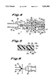
FIG. 9(a) is a plan view of the contact strip;
FIG. 9(b) is a side elevation of the contact strip shown in FIG. 9(a); and
FIG. 9(c) is a rear elevation of a portion of the contact strip as shown in FIG. 9(a);
As best seen in FIGS. 1-3, the plug connector consists of a connector base 10 comprising strip-form contacts 21 supported in upper and lower horizontal rows by a plastic (synthetic resin) connector base part 30, a metal hood-form shielding cover 2 mounted on the connector base 10 and an insulating, bipartite, pressure-contact cover for enclosing upper and lower rear parts for the connector base 10.
The cover 2 is formed in one piece with a flanged part 2a which extends rearwardly for mounting on a transverse rib portion formed centrally of the connector base, and defines a frontal opening 2b.
The connector base 10 projects at a front into the frontal opening 2b of the cover 2a forming a plug unit for connection with a complementary receptacle unit. A flat cable 5 is connected to a rear part of the connector base 10 and extends rearwardly therefrom. An insulating plug 45 is inserted in a cavity in the rear end of the connector base 10.
As shown in FIGS. 4-8, the upper and lower rows of contact parts 21 are arranged in opposed, back-two-back, parallel relation, on respective opposite faces of a supporting plastic base part 30.
As shown in FIG. 9, the contact parts 21 are manufactured by stamping and forming from sheet metal and extend rearwardly in coextensive, parallel, relation from respective leads 29a and 29b of a transverse carrier 29 integrally joined to their front ends.
Each contact part 21 comprises a forward part 22, a central part 24, and a rear part 26.
The rear part 26 is bent to extend perpendicularly at a rear end forming an upstanding electrical connecting part 27 having a bifurcation providing two prongs 27a and 27b which define between them a wire receiving slot 27b into which the cable core wire 5a is pushed on penetration of the insulating sheath by the prongs.
The rear parts 26 of the contact parts 21 are alternately long and short so that, as shown in FIG. 9(A) the connecting parts 27 are staggered longitudinally. The contact parts 21 having longer rear parts 26 are bent or looped upwardly and fastened to the leads 29a while those of the short rear parts 26 are fastened to the substantially straight leads 29b supported by the carrier 29.
In addition, small lateral projections 22a are formed in both side surfaces of the forward parts 22 of the contact parts 21 and the tips are both reduced in thickness and deformed downwardly by striking to protrude below the level of the remainders of the contact parts to ensure that they are covered by a sufficient amount of plastic for reliable retention.
The contact strips 20 are supported by a mold member (not shown) in opposed, back-to-back, substantially parallel relation at a specific, constant spacing apart, one above the other. The resin or plastic material is injected into the mold and the base part 30 (FIG. 2), shown in FIGS. 4-7 and 9, formed by the insert molding step.
During the molding process, the intermediate support 31 is formed between the upper and lower contact parts 21 extending from their forward parts 22 to their middle parts 24 and pairs of transversely extending walls 32a, 32b, and 32c, are formed in spaced apart, parallel relation upstanding from the intermediate support and extending across the central parts 24 of the contact parts 21 and joined by rearwardly extending ribs 34 and 36, with walls 32b and 32c integrally joined at both opposite ends with flange forming portions 35 formed on respective opposite sides of the base part. A pair of transversely extending rear support parts 33 (33a and 33b) is also formed, such parts extending rearwardly from the upper surfaces of the rear parts 26 of the contact parts 21 and integrally joined to rearwardly extending flange portions 37 formed on respective opposite sides of the base part and which carry cover latching projections referred to below.
Thus, the intermediate molded parts 31, the central supporting walls 32 (32a, 32b, and 32c) the rear support 33, and the flange parts 35 are integrally formed as a one-piece body by the insert molding process.
The central parts 24 of the contacts extending between respective walls 32a, 32b, 32c and rear support parts 33a and 33b are covered by a very thin film of plastic formed by the molding process, as shown in FIG. 7 (but not shown in FIG. 4).
It will be apparent to the skilled technician that the mold used for the formation of the above-described body structure has cavity defining parts which correspond to the aforementioned intermediate molded parts 31, walls 32, rear support parts 33 and the rear flange parts 35.
As shown in FIG. 4, a rearwardly opening cavity is formed by a mold part between the rear parts 26 of the upper and lower contact parts 21, i.e., between the rear support parts 33 of the two series of contacts. The mold part supports the rear contact parts 26 during the molding step.
The front parts 22 of the contact parts 21 are also reliably supported by the carrier 29 to which they are integrally attached. The reliable support of the front parts 22 and the rear parts 26 during the insert molding enables the positional accuracy of the contact parts to be obtained with a high degree of precision.
As the cavity or space 40 remains after molding, to obviate the possibility of inward deformation of the rear parts 26 under the insertion force of a flat cable and to assure insulation between the contact parts 26, a plug part 45 made from insulating material is forcibly inserted in the cavity 40.
The rear supporting parts 33 of the base part 30 surround and cover root ends (i.e., bent part) of the electrically connecting parts 27 thereby supporting and strengthening the root parts obviating risk of deformation or damage during pressure connection to a flat cable. In addition, the rear supporting parts 33 extend completely over the rear, horizontal extending parts 26 and extend between side surfaces of the contact parts 21 securing such parts.
In addition, the end 31a of the intermediate molded part 31, as shown in FIG. 4, protrudes outwardly and upwardly beyond the ends of the contact parts 21 thereby supporting such parts. As shown in FIG. 5, upper edge portions of the side surfaces of the front parts 22 of the contacts are exposed and the connecting outer surfaces 22b are completely exposed for connecting purposes.
The anchoring projections 22a formed in both sides of the contact parts 21 are completely covered by the intermediate molded parts 31 so that the leading ends of the contacts are supported by and prevented from being lifted away from the molded part 31.
After the base part 30 is formed by the insert molding step described above, the carrier 29 is cut away along the line X--X in FIGS. 6 and 7 completing the contact base 10.
Subsequently, the shielding cover 2 is installed on the contact base 10 and, as shown in FIG. 3, ends of flat cables 5 are aligned with respective pressure-contact covers 4.
The covers 4 are hermaphroditic and mountable on the housing in preliminary and final positions. Each cover is provided with a first latch 41 engaging with a projection 43 formed on the housing body, primarily for retaining the cover on the housing body, and a second latch 42 engaging with the projection 43, for securing the cover to the housing body after the cable is press-terminated in the contacts by pressing down the cable cover. The first latch 41 has a width half that of the second latch 42.
In the preliminary position, a large force is not applied to the cable cover and thus the first latch has a smaller width, but the second latch has a larger width, because it is subject to a large force.
Since the pair of first latches have a width equivalent to or smaller than that of the second latch, the first latches do not abut or engage each other, and thus the connector body can have a low profile.
The elimination of a post-molding contact insertion step enables the connection to be economically manufactured from less plastic material while the in-molding method of the invention enables increased accuracy of contact location at closer pitch.

Claims (7)

We claim:
1. A method for manufacturing a plug connector of the type comprising a first and a second series of elongate, strip-form contacts having elongate connecting portions adjacent leading ends with front connecting surfaces exposed on respective opposite faces of a supporting insulating base for engagement with complementary surfaces of a female connector to establish electrical connection therewith, comprising the steps of:
providing first and second contact strips comprising a first and a second series of elongate, strip-form contacts, respectively each contact having a connecting portion adjacent a leading end with an elongate, front connecting surface and an underlying back surface joined thereto by side surfaces the contacts of respective series being, attached at respective leading ends to respective, transversely extending carrier strips;
supporting respective contact strips in a mold with the contacts extending in the same direction away from the respective carrier strips and the contacts of one strip located with respective back surfaces in opposed, back-to-back, coplanar relation with, and at a predetermined spacing apart from the respective back surfaces of the contacts of the other strip;
forming a supporting base by injecting plastic material into the mold at locations between the two contact series covering the opposed back surfaces of the connecting portions and at least part of the side surfaces of portions of the contacts adjacent the carrier strips, while maintaining the front, connecting surfaces exposed so as to extend in parallel relation rearwardly across opposite faces of the base from a leading end thereof;
forming a connector base by removing the carrier strips from the series of supported contacts; and,
locating a cover on the connector base so formed.
2. A method according to claim 1 including the step of supporting rear end portions of each contact remote from the carrier strip by placing a mold member therebetween during the molding of the base.
3. A method according to claim 1 in which the contact strips are supported with front connecting surface of each contact extending proud of the base material.
4. A method according to claim 1 including the step of providing, prior to the supporting step, anchoring portions protruding laterally from respective opposite side surfaces of the connecting portions and covering said anchoring portions by the plastic material by the injection thereof.
5. A method according to claim 1 including the step of forming, prior to the supporting step, arm pairs on trailing ends of respective contacts to extend perpendicularly thereto, respective arms of each pair defining between them wire receiving slots and the slots of contacts of each series opening away from each other, in opposite directions; forming a cavity underlying respective arm pairs by the injection step and force-fitting an insulating plug into the cavity thereby supporting the trailing ends of respective series of contacts in predetermined spaced apart relation.
6. A method for manufacturing a plug connector of the type comprising a first and a second series of elongate, strip-form contacts having elongate connecting portions adjacent leading ends with front connecting surfaces exposed on respective opposite faces of a supporting insulating base for engagement with complementary surfaces of a female connector to establish electrical connection therewith, comprising the steps of:
providing first and second contact strips comprising a first and a second series of elongate, strip-form contacts, respectively each contact having a connecting portion adjacent a leading end with an elongate, front connecting surface and an underlying back surface joined thereto by side surfaces, and anchoring portions protruding laterally from respective opposite side surfaces of the connecting portions, the contacts of respective series being, attached at respective leading ends to respective, transversely extending carrier strips; arm pairs on trailing ends of respective contacts extending perpendicularly thereto, respective arms of each pair defining between them wire receiving slots and the slots of contacts of each series opening away from each other, in opposite directions;
supporting respective contact strips in a mold with the contacts extending in the same direction away from the respective carrier strips and the contacts of one strip located with respective back surfaces in opposed, back-to-back, coplanar relation with, and at a predetermined spacing apart from the respective back surfaces of the contacts of the other strip and supporting rear end portions of each contact remote from the carrier strip by placing a mold member therebetween;
forming a supporting base by injecting plastic material into the mold at locations between the two contact series covering the opposed back surfaces of the connecting portions and at least part of the side surfaces of portions of the contacts adjacent the carrier strips including the anchoring portions, while maintaining the front, connecting surfaces exposed so as to extend in parallel relation rearwardly across opposite faces of the base from a leading end thereof, the mold member forming a cavity underlying respective arm pairs;
forming a connector base by removing the carrier strips from the series of supported contacts;
force-fitting an insulating plug into the cavity thereby supporting the trailing ends of respective series of contacts in predetermined spaced apart relation; and,
locating a cover on the connector base so formed.
7. A method according to claim 6 in which the contact strips are supported with the front connecting surface of each contact extending proud of the base material.
US07/800,829 1991-08-30 1991-11-27 Method of making in-molded plug connector Expired - Fee Related US5201883A (en)

Applications Claiming Priority (2)

Application Number Priority Date Filing Date Title
JP3-245089 1991-08-30
JP03245089A JP3078616B2 (en) 1991-08-30 1991-08-30 Plug connector and manufacturing method thereof

Publications (1)

Publication Number Publication Date
US5201883A true US5201883A (en) 1993-04-13

Family

ID=17128447

Family Applications (1)

Application Number Title Priority Date Filing Date
US07/800,829 Expired - Fee Related US5201883A (en) 1991-08-30 1991-11-27 Method of making in-molded plug connector

Country Status (2)

Country Link
US (1) US5201883A (en)
JP (1) JP3078616B2 (en)

Cited By (29)

* Cited by examiner, † Cited by third party
Publication number Priority date Publication date Assignee Title
US5274917A (en) * 1992-06-08 1994-01-04 The Whitaker Corporation Method of making connector with monolithic multi-contact array
EP0693802A3 (en) * 1994-07-19 1996-03-06 Molex Inc
US5539978A (en) * 1993-09-24 1996-07-30 Siemens Aktiengesellschaft Method for producing groups of contact elements for plug connectors
EP0729206A2 (en) * 1995-02-22 1996-08-28 The Whitaker Corporation PCMCIA input/output card connector
EP0762560A2 (en) * 1995-09-07 1997-03-12 Molex Incorporated Electrical connector with embedded terminals
WO1997015100A1 (en) * 1995-10-17 1997-04-24 Honeywell Inc. Electrical connector with different lead arrangements at its opposite ends
US5639248A (en) * 1993-12-14 1997-06-17 Molex Incorporated Electric connector assembly for use in couplings two printed boards
AU682454B3 (en) * 1996-12-11 1997-10-02 Lan-Jen Tsang A plugger of a full plug
WO1997036351A1 (en) * 1996-03-28 1997-10-02 The Whitaker Corporation High density electrical connector
US5722861A (en) * 1996-02-28 1998-03-03 Molex Incorporated Electrical connector with terminals of varying lengths
US5761805A (en) * 1996-03-28 1998-06-09 The Whitaker Corporation Method of making a high density electrical connector
US5766033A (en) * 1996-03-28 1998-06-16 The Whitaker Corporation High density electrical connector
US5822849A (en) * 1993-12-10 1998-10-20 U.S. Philips Corporation Hinged circuit assembly with multi-conductor framework
US5848920A (en) * 1996-07-16 1998-12-15 Molex Incorporated Fabrication of electrical terminals for edge card connectors
WO1999016155A1 (en) * 1997-09-19 1999-04-01 Framatome Connectors International Process for producing a flat connector comb which can be moulded into an enclosure
US6004160A (en) * 1997-03-25 1999-12-21 The Whitaker Corporation Electrical connector with insert molded housing
US6010370A (en) * 1996-12-20 2000-01-04 Molex Incorporated Insert molded electrical connector and method for producing same
US6099359A (en) * 1997-06-20 2000-08-08 Molex Incorporated Terminal retention system
US6125535A (en) * 1998-12-31 2000-10-03 Hon Hai Precision Ind. Co., Ltd. Method for insert molding a contact module
US6152761A (en) * 1997-06-13 2000-11-28 Thomas & Betts International, Inc. Overmolded connector and method for manufacturing same
EP1063738A1 (en) * 1999-06-22 2000-12-27 Molex Incorporated Insert-molded electrical connector and method of manufacture
US6176748B1 (en) 1998-11-24 2001-01-23 Molex Incorporated Terminal positioning system
US6187242B1 (en) * 1997-09-03 2001-02-13 Yazaki Corporation Connector molding method
US6219913B1 (en) * 1997-01-13 2001-04-24 Sumitomo Wiring Systems, Ltd. Connector producing method and a connector produced by insert molding
US6370771B1 (en) * 1998-10-29 2002-04-16 Hon Hai Precision Ind. Co., Ltd. Method for making an electrical connector
US20030017752A1 (en) * 2001-07-23 2003-01-23 Sumitomo Wiring Systems, Ltd. Connector and method for producing the same
US6676875B1 (en) * 1999-11-30 2004-01-13 Moldec Co., Ltd. Method of forming receptacle connector insert
DE10227602A1 (en) * 2002-06-20 2004-01-15 Lisa Dräxlmaier GmbH Pluggable connector for flat- or ribbon-cable for automobile, has contacts fixedly joined to exposed conductor ends of cable
CN102403597A (en) * 2010-09-08 2012-04-04 爱沛斯株式会社 Electric connector and manufacturing method thereof

Families Citing this family (4)

* Cited by examiner, † Cited by third party
Publication number Priority date Publication date Assignee Title
JP3227388B2 (en) 1995-08-02 2001-11-12 キヤノン株式会社 Ink absorber, ink tank using the ink absorber, inkjet cartridge integrating ink tank and inkjet recording head, method of manufacturing ink tank, and fiber mass used in the ink tank
JP3833122B2 (en) * 2002-02-13 2006-10-11 日本エー・シー・ピー株式会社 Optical coupler for optical connection, optical branching or optical assembly
JP6334342B2 (en) * 2014-09-17 2018-05-30 東芝メモリ株式会社 Semiconductor device
JP6757611B2 (en) * 2016-07-20 2020-09-23 ヒロセ電機株式会社 Electrical connector with terminal support

Citations (7)

* Cited by examiner, † Cited by third party
Publication number Priority date Publication date Assignee Title
US3618207A (en) * 1969-09-02 1971-11-09 Burroughs Corp Method of manufacturing strip connectors
US3760335A (en) * 1971-05-27 1973-09-18 Amp Inc Pre-loaded electric connector
US4197636A (en) * 1976-06-01 1980-04-15 Olympus Optical Co., Ltd. Method of producing a structure of connection terminals
US4337574A (en) * 1978-12-14 1982-07-06 Amp Incorporated Method of manufacturing electrical connector receptacles
US4445736A (en) * 1982-03-31 1984-05-01 Amp Incorporated Method and apparatus for producing a premolded packaging
US4628597A (en) * 1983-11-25 1986-12-16 Meehan Robert F Method of making an electrical connector
US4795602A (en) * 1986-03-19 1989-01-03 Pretchel David A Two pin shunt and molding method

Patent Citations (7)

* Cited by examiner, † Cited by third party
Publication number Priority date Publication date Assignee Title
US3618207A (en) * 1969-09-02 1971-11-09 Burroughs Corp Method of manufacturing strip connectors
US3760335A (en) * 1971-05-27 1973-09-18 Amp Inc Pre-loaded electric connector
US4197636A (en) * 1976-06-01 1980-04-15 Olympus Optical Co., Ltd. Method of producing a structure of connection terminals
US4337574A (en) * 1978-12-14 1982-07-06 Amp Incorporated Method of manufacturing electrical connector receptacles
US4445736A (en) * 1982-03-31 1984-05-01 Amp Incorporated Method and apparatus for producing a premolded packaging
US4628597A (en) * 1983-11-25 1986-12-16 Meehan Robert F Method of making an electrical connector
US4795602A (en) * 1986-03-19 1989-01-03 Pretchel David A Two pin shunt and molding method

Cited By (39)

* Cited by examiner, † Cited by third party
Publication number Priority date Publication date Assignee Title
US5451169A (en) * 1992-06-08 1995-09-19 The Whitaker Corporation Connector with monolithic multi-contact array
US5274917A (en) * 1992-06-08 1994-01-04 The Whitaker Corporation Method of making connector with monolithic multi-contact array
US5539978A (en) * 1993-09-24 1996-07-30 Siemens Aktiengesellschaft Method for producing groups of contact elements for plug connectors
US5822849A (en) * 1993-12-10 1998-10-20 U.S. Philips Corporation Hinged circuit assembly with multi-conductor framework
US5639248A (en) * 1993-12-14 1997-06-17 Molex Incorporated Electric connector assembly for use in couplings two printed boards
US5842875A (en) * 1993-12-14 1998-12-01 Molex Incorporated Electric connector assembly for use in coupling two printed boards
EP0693802A3 (en) * 1994-07-19 1996-03-06 Molex Inc
EP0729206A2 (en) * 1995-02-22 1996-08-28 The Whitaker Corporation PCMCIA input/output card connector
EP0729206A3 (en) * 1995-02-22 1997-10-08 Whitaker Corp PCMCIA input/output card connector
EP0762560A3 (en) * 1995-09-07 1998-04-08 Molex Incorporated Electrical connector with embedded terminals
US5772474A (en) * 1995-09-07 1998-06-30 Molex Incorporated Electrical connector with embedded terminals
EP0762560A2 (en) * 1995-09-07 1997-03-12 Molex Incorporated Electrical connector with embedded terminals
WO1997015100A1 (en) * 1995-10-17 1997-04-24 Honeywell Inc. Electrical connector with different lead arrangements at its opposite ends
US5722861A (en) * 1996-02-28 1998-03-03 Molex Incorporated Electrical connector with terminals of varying lengths
WO1997036351A1 (en) * 1996-03-28 1997-10-02 The Whitaker Corporation High density electrical connector
US5761805A (en) * 1996-03-28 1998-06-09 The Whitaker Corporation Method of making a high density electrical connector
US5766033A (en) * 1996-03-28 1998-06-16 The Whitaker Corporation High density electrical connector
US5848920A (en) * 1996-07-16 1998-12-15 Molex Incorporated Fabrication of electrical terminals for edge card connectors
AU682454B3 (en) * 1996-12-11 1997-10-02 Lan-Jen Tsang A plugger of a full plug
US6010370A (en) * 1996-12-20 2000-01-04 Molex Incorporated Insert molded electrical connector and method for producing same
US6219913B1 (en) * 1997-01-13 2001-04-24 Sumitomo Wiring Systems, Ltd. Connector producing method and a connector produced by insert molding
US6004160A (en) * 1997-03-25 1999-12-21 The Whitaker Corporation Electrical connector with insert molded housing
US6152761A (en) * 1997-06-13 2000-11-28 Thomas & Betts International, Inc. Overmolded connector and method for manufacturing same
US6099359A (en) * 1997-06-20 2000-08-08 Molex Incorporated Terminal retention system
US6187242B1 (en) * 1997-09-03 2001-02-13 Yazaki Corporation Connector molding method
WO1999016155A1 (en) * 1997-09-19 1999-04-01 Framatome Connectors International Process for producing a flat connector comb which can be moulded into an enclosure
US6370771B1 (en) * 1998-10-29 2002-04-16 Hon Hai Precision Ind. Co., Ltd. Method for making an electrical connector
SG81328A1 (en) * 1998-11-24 2001-06-19 Molex Inc Terminal positioning system
US6176748B1 (en) 1998-11-24 2001-01-23 Molex Incorporated Terminal positioning system
US6125535A (en) * 1998-12-31 2000-10-03 Hon Hai Precision Ind. Co., Ltd. Method for insert molding a contact module
EP1063738A1 (en) * 1999-06-22 2000-12-27 Molex Incorporated Insert-molded electrical connector and method of manufacture
KR100360999B1 (en) * 1999-06-22 2002-11-18 몰렉스 인코포레이티드 Insert-molded electrical connector and method of manufacture
US6676875B1 (en) * 1999-11-30 2004-01-13 Moldec Co., Ltd. Method of forming receptacle connector insert
US20030017752A1 (en) * 2001-07-23 2003-01-23 Sumitomo Wiring Systems, Ltd. Connector and method for producing the same
US6796852B2 (en) * 2001-07-23 2004-09-28 Sumitomo Wiring Systems, Ltd. Connector and method for producing the same
DE10227602A1 (en) * 2002-06-20 2004-01-15 Lisa Dräxlmaier GmbH Pluggable connector for flat- or ribbon-cable for automobile, has contacts fixedly joined to exposed conductor ends of cable
DE10227602B4 (en) * 2002-06-20 2017-06-22 Lisa Dräxlmaier GmbH Method for producing a connector for flat conductors
CN102403597A (en) * 2010-09-08 2012-04-04 爱沛斯株式会社 Electric connector and manufacturing method thereof
CN102403597B (en) * 2010-09-08 2014-10-22 第一精工株式会社 Electric connector and manufacturing method thereof

Also Published As

Publication number Publication date
JP3078616B2 (en) 2000-08-21
JPH0562733A (en) 1993-03-12

Similar Documents

Publication Publication Date Title
US5201883A (en) Method of making in-molded plug connector
US5772474A (en) Electrical connector with embedded terminals
US4159158A (en) Displation connector having improved terminal supporting means
US4758182A (en) Electric connector
US5104336A (en) Flat cable connector
US4648665A (en) Electronic key assemblies
JP2934845B2 (en) Method of manufacturing terminal for edge card connector
US6065951A (en) Mold for use in manufacturing an electrical connector
US5888096A (en) Electrical connector, housing and contact
US6155886A (en) Electrical connector and method for making the same
EP0853356B1 (en) A connector producing method and a connector produced by insert molding and a use thereof
KR100192624B1 (en) Electrical connector terminal and method of making electrical connector with the same
EP0846350B1 (en) Method for making surface mountable connectors
US4253722A (en) Insulation pierce-type connector for ribbon cable
US20170012376A1 (en) Card connector
US5281165A (en) Electrical connector shroud adapted for shorting bar removal
JPH0154824B2 (en)
CA2394887A1 (en) Electrical connector with overmolded and snap locked pieces
US4676576A (en) Communications connector
US5542851A (en) Electrical connector with improved grounding
JP2934844B2 (en) Edge card connector for printed circuit boards
US6764357B2 (en) Electrical connector and method of assembling the same
GB1584910A (en) Electrical connector housing and electrical connector
US4752246A (en) Preloaded spring contact electrical terminal
US6890192B2 (en) Sequential connection-type connector and additional contact used in the same

Legal Events

Date Code Title Description
AS Assignment

Owner name: KEL CORPORATION, JAPAN

Free format text: ASSIGNMENT OF ASSIGNORS INTEREST.;ASSIGNORS:ATOH, KIYOSHI;TANABE, SHINJI;REEL/FRAME:005999/0968

Effective date: 19920109

FEPP Fee payment procedure

Free format text: PAYOR NUMBER ASSIGNED (ORIGINAL EVENT CODE: ASPN); ENTITY STATUS OF PATENT OWNER: SMALL ENTITY

FPAY Fee payment

Year of fee payment: 4

FPAY Fee payment

Year of fee payment: 8

REMI Maintenance fee reminder mailed
LAPS Lapse for failure to pay maintenance fees

Free format text: PATENT EXPIRED FOR FAILURE TO PAY MAINTENANCE FEES (ORIGINAL EVENT CODE: EXP.); ENTITY STATUS OF PATENT OWNER: SMALL ENTITY

STCH Information on status: patent discontinuation

Free format text: PATENT EXPIRED DUE TO NONPAYMENT OF MAINTENANCE FEES UNDER 37 CFR 1.362

FP Lapsed due to failure to pay maintenance fee

Effective date: 20050413