US5201683A - Internal structure for a crawling and talking doll - Google Patents
Internal structure for a crawling and talking doll Download PDFInfo
- Publication number
- US5201683A US5201683A US07/741,667 US74166791A US5201683A US 5201683 A US5201683 A US 5201683A US 74166791 A US74166791 A US 74166791A US 5201683 A US5201683 A US 5201683A
- Authority
- US
- United States
- Prior art keywords
- doll
- crawling
- pair
- cog
- axle
- Prior art date
- Legal status (The legal status is an assumption and is not a legal conclusion. Google has not performed a legal analysis and makes no representation as to the accuracy of the status listed.)
- Expired - Lifetime
Links
Images


Classifications
-
- A—HUMAN NECESSITIES
- A63—SPORTS; GAMES; AMUSEMENTS
- A63H—TOYS, e.g. TOPS, DOLLS, HOOPS OR BUILDING BLOCKS
- A63H11/00—Self-movable toy figures
- A63H11/18—Figure toys which perform a realistic walking motion
-
- A—HUMAN NECESSITIES
- A63—SPORTS; GAMES; AMUSEMENTS
- A63H—TOYS, e.g. TOPS, DOLLS, HOOPS OR BUILDING BLOCKS
- A63H3/00—Dolls
- A63H3/28—Arrangements of sound-producing means in dolls; Means in dolls for producing sounds
Definitions
- the invention refers to a crawling and talking doll, which has the special feature of incorporating a series of elements functionally combined one with another in order to establish an electromechanical mechanism which, once it is activated, makes the doll, when lying face downwards (on her hands and knees), carry out successively a series of movements at the same time as it gives out two kinds of messages, depending on the position at that moment.
- the movements which are carried out result in the doll crawling along and simultaneously giving out one type of message; after a period of time, the doll stops crawling and begins to raise the trunk of her body and her head, turning the latter to one side to look upwards, giving out a different message with this second type of movement.
- the doll stops and begins to lower itself to return to its original position, repeating the cycle indefinitely, unless a general switch is activated, triggered either when a dummy is put in the doll's mouth or the doll is picked up and put in the upright position, by means of a ball switch which will operate independently of the general switch triggered by the dummy.
- the whole mechanism or system includes a general activation motor and a motor for the activation of the sound disc or message emitter, both operating independently, although they are connected with each other so that, as a result of the functioning of the elements corresponding to the sound device, the motor of the general mechanism starts to work.
- This motor had previously interrupted its functioning because at a given moment it is disconnected, stopping the general mechanism, although the sound disc motor continues operating in order to give out the message, and also to start up the motor of the general mechanism again, as will be explained in detail below.
- the general mechanism includes a pair of cog wheels which are set in motion simultaneously, since they are assembled on the same axle that operates the arms and legs, by means of a long cogged pinion or cylinder, which in turn is set in motion by a transmission coming from the activation motor itself.
- these two cog wheels On the sides that face each other, these two cog wheels have ramp like protrusions which, in a specific position, are so placed that the inclined rims of these ramps come into contact with each other, making the two wheels reach the closest position possible in respect to each other.
- One of these wheels has one more cog, so that the rotation speed of both is different. This causes one ramp to push the other, and, eventually, one of the wheels to move away from the other.
- This movable wheel is, of course, assembled freely, so that it can move axially on its assemblage axle. This separation, which is brought about against the action of a spring, makes a joint pinion in the opposite side of that wheel engage another wheel which transmits the movement to the arms, as well as to the head, and, at a given moment, to the sound device.
- That fundamental part is a cam whose rotation axle is eccentric and includes a peripheral sector whose radius of curvature has its center in the rotation axle itself.
- One of the ends of a swinging, elbowed arm rests permanently on the said cam. The other end constitutes the means for the transmission of the different movements.
- the resting end of the above mentioned lever causes the pressure to rest on one or another of the sectors included in the periphery, so that when it rests on a particular point, the doll, as it were, crawls and gives out a message.
- the doll When, in its rotation, it rests on the sector whose radius of curvature corresponds with the rotation axle of the cam, then the doll reaches its highest position, having previously rested on the sector in which the beginning of the elevation towards that highest position takes place, and finally it rests on the last sector of the cam, during which a lowering of the doll towards the low position is carried out.
- the doll remains in the highest position for a period of time as a result of the disconnection of the motor of the general mechanism.
- This disconnection is brought about by a small protrusion joined to the inner side of the said cam which activates a switch that opens the supply circuit of the motor. Therefore the mechanism stops, and the doll remains in the raised position, although during this period the doll moves due to impulses produced by the working of the sound device.
- This lever also closes the circuit of the general activation motor, so that the mechanism starts working again and causes the raising of the doll and subsequent lowering to its original position. Therefore, we could say that the movement, from the beginning of the raising of the doll to the beginning of its lowering, is caused by the actual impulses of its voice, since it is the sound device which starts up the general mechanism, having previously been disconnected and stopped at the moment when the raising of the doll begins, it is necessary to clarify that the lowest position of the doll, that is, when it is crawling, corresponds to that position in which the ramp like protrusions of the two basic wheels of the gear are disengaged, that is to say, not coming into contact with each other; whereas the highest position of the doll corresponds to that in which these ramp like protrusions face each other, so that the course during which one of the ramps slides over the other corresponds to the raising phase of the doll, from the low crawling position to the high position.
- the legs of the doll move by means of several elements, each made up of a sort of long, thin metal plate or rod with an intermediate stretch in the form of a spring or elastic part, that not only allows the doll to crawl, but also, because of the particular positioning of the above elements, allows the doll to adopt a sitting position without any difficulty.
- FIG. 1 shows a diagram of the general mechanism in the position which corresponds to the doll crawling, but beginning to raise.
- FIG. 2 shows the same diagram of the general mechanism in the highest position of the doll.
- FIG. 3 shows the position of the main cam when the general mechanism corresponds to the mechanism shown in FIG. 1, likewise showing the resting of the respective elbowed lever by which the movements are transmitted.
- FIG. 4 shows the same part shown in the former figure, but seen from the inside in order to appreciate the protrusion of the cam, responsible for the opening and closing of the circuit at a given moment.
- FIG. 5 shows the side opposite to the one shown in FIGS. 3 and 4, with the mechanism in the same position.
- FIG. 6 shows another position of the main cam, corresponding to the highest position of the doll.
- FIG. 7 shows the same part shown in the former figure, but seen from the inside in order to appreciate how the protrusion of the cam disconnects the supply circuit of the general motor, the whole general mechanism stopping at the moment in which that position is reached.
- FIG. 8 shows the side opposite to the one shown in FIGS. 6 and 7, with the mechanism in the same position.
- FIG. 9 shows the ground plan of the inside of the box containing the sound device, also illustrating the arm with the needle, the track of the sound disc and the parts responsible for closing the circuit which sets the general mechanism in motion.
- FIG. 10 shows a ball-type switch completing the circuit, which corresponds to the operating position of the doll.
- FIG. 11 shows a detail in section of the same switch as in the former figure, in the position of the disconnection of the circuit, which corresponds to the raising and sitting positions of the doll.
- FIG. 12 shows the plan corresponding to the general electric circuit included in the doll, illustrating the association or connection between the parts of the activation circuit of the general mechanism and the sound device.
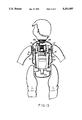
- FIG. 13 shows a general diagram of the doll mechanism within a doll body.
- the general, mechanism moves when the motor is activated (1), and this, by means of a transmission system consisting of pulleys and a belt (2), makes the pinion turn (3), which, as it rotates, engages the cog wheel (4), joined axially to a cogged cylinder (5), in which two cog wheels (6 and 7) are permanently engaged.
- a transmission system consisting of pulleys and a belt (2)
- the pinion turn (3) which, as it rotates, engages the cog wheel (4), joined axially to a cogged cylinder (5), in which two cog wheels (6 and 7) are permanently engaged.
- One of these has one cog less so that their speed of rotation is different.
- These wheels (6 and 7) have, on their facing sides, a number of complementary protrusions (11) with oblique edges (12), which establish in each case what could be considered as ramps. These come into contact by means of the oblique edges (12) at a particular moment or position, such as the stage illustrated in FIG. 1, to later move apart without contact of any type, such as it is illustrated in FIG. 2, although in this case they are facing each other and this figure corresponds to the position that immediately follows that when the above-mentioned edges, which determine the ramps, have stopped being in contact.
- a cog wheel (19) is assembled, on which the pinion (10) can engage when the wheel (7) moves away from the other wheel (6), so that the rotation of the pinion (5) and of the wheel (4) assembled on the axle (18) are independent of the rotation of the wheel (19) and cam (13) assembled on the axle (17).
- the axle itself (8) next to the swinging lever (13), has a small cam (20) joined to it, after which the above-mentioned axle extends through a section on which the articulation element (21) and the legs and arms of the doll are articulated.
- This element which is straight, has an intermediate elastic stretch (22), in the form of a spring, which allows it to transmit adequately the movements to the legs so that the doll crawls and can also adopt the sitting .-position.
- the swinging levers (13 and 13') are elbowed, and whereas the free end of the first has an adjunct (23) which joins with some known parts (24) in order to bring about the movements of the head, the free end of the second lever (13') operates an arm (25), also swinging, with a small hole (26) at its end by which it is joined to the arm with the needle (27) belonging to the sound device, which is described below.
- the respective element (21') with its intermediate elastic stretch (22') is assembled so that it transmits the movement of the leg of that side, and the respective arm of the doll is assembled at the end of that side of the axle (8).
- the main cam (16) like the other (16'), has its periphery in such a way that can be considered as made up of three successive sectors confined to the letters A, B and C, in which the radius of curvature of sector AC has its center precisely on the axle (17).
- This main cam (16) has, joined to it on its inner side, a sort of secondary cam (28) with a protrusion (29). The latter, as it rotates, is able to push a conductor (30) which opens and closes the respective supply circuit of the motor (1).
- the end of this moving part is able to contact the arm (27), according to its position.
- the end of this moving part intercepts and pushes the arm (27) which in turn pushes a hoop (34) which comes into contact with the terminal (35), closing a secondary supply circuit of the general motor (1); whereas when this handle is outside the sphere of the arm (27), the latter hits against the pivot (36), causing the disconnection of the corresponding above mentioned circuit.
- the arm (27) is connected to a spring with a pushing action (36').
- FIG. 12 shows the general supply circuit of the motor (1), powered by batteries (37), and has on one side a general switch (38) which can be activated, for example, by a dummy (39) when it is taken out of the doll's mouth.
- This switch (38) disconnects the whole system when the dummy (39) is inserted.
- the circuit is joined to a secondary switch (40), for example the classic "ball type", shown in FIGS. 10 and 11 which illustrate that in the functioning position of the doll, the ball (42) keeps the motor (1) supplied by means of the conductor (41), whereas in any other position of the doll, the ball (42) moves and opens the circuit by disconnecting that conductor.
- the said ball (42) is inside a box (43) and activates a connector (44), opening and closing the circuit, as has just been explained.
- the conductors (45 and 46) coming out of the sound device can supply the motor (1) when contact is made between the hoop (34) and the connector (35). This takes place because the motor of the sound device (31) is supplied independently through the conductors (47 and 48) by means of the secondary switch (40).
- the doll remains in that position while the cam (16) passes from position C to position A, that is, while it goes through the stretch CA, whose radius of curvature has the same center as the axle (17) of the eccentric (16).
- the doll moves by impulses due to the functioning of the sound device which connects and disconnects the secondary supply circuit of the motor (1). Besides these movements by impulses, a movement of the head occurs.
- the sound device has a permanent supply, and in these above-mentioned movements the lever (13') will have come into contact with the lever or arm (25), which by means of its connection with the handle (33) pushes in some cases the arm with the needle (27), changes the track and gives out other voices.
- This pushing brings about precisely the closing of the secondary supply circuit of the motor (1) that takes place when the hoop (34), pushed by the arm, contacts the terminal (35), so that, through these conductors (45 and 46), the secondary circuit is closed and the activation of the general mechanism takes place, as had been said previously.
- the arm (27) is no longer being pushed, then the secondary circuit is disconnected again and the cycle is repeated in this way during a period of time.
- the mechanism when the doll is in its highest position, operates by impulses given out by the sound device.
- the protrusion (29) ceases to activate the terminal (30) and allows the general circuit to close again, whereby the movement of the mechanism starts bringing about the lowering of the doll's body until it reaches the normal position of crawling. This movement takes place during the time elapsed between point B and A of the eccentric (16). From that moment on, the original position is reached and the cycle will be repeated constantly unless the general switch (38) is turned off either by introducing the dummy (39) or by picking up the doll and placing it in a more or less upright position, activating the ball switch (40) which also closes and disconnects the whole circuit, including the sound device.
Abstract
Description
Claims (8)
Applications Claiming Priority (2)
| Application Number | Priority Date | Filing Date | Title |
|---|---|---|---|
| ES09101801A ES2051156B1 (en) | 1991-07-31 | 1991-07-31 | DRAGGING AND SPEAKING DOLL |
| ES9101801 | 1991-07-31 |
Publications (1)
| Publication Number | Publication Date |
|---|---|
| US5201683A true US5201683A (en) | 1993-04-13 |
Family
ID=8273202
Family Applications (1)
| Application Number | Title | Priority Date | Filing Date |
|---|---|---|---|
| US07/741,667 Expired - Lifetime US5201683A (en) | 1991-07-31 | 1991-08-07 | Internal structure for a crawling and talking doll |
Country Status (4)
| Country | Link |
|---|---|
| US (1) | US5201683A (en) |
| CA (1) | CA2048587C (en) |
| ES (1) | ES2051156B1 (en) |
| GB (1) | GB2258820B (en) |
Cited By (6)
| Publication number | Priority date | Publication date | Assignee | Title |
|---|---|---|---|---|
| US5468172A (en) * | 1991-08-07 | 1995-11-21 | Basile; Pauline R. | Doll including recorded message means |
| US6135845A (en) * | 1998-05-01 | 2000-10-24 | Klimpert; Randall Jon | Interactive talking doll |
| EP1064976A1 (en) * | 1999-06-30 | 2001-01-03 | Onilco Innovacion S.A. | Crawling doll fitted with search and direction change device |
| EP1071498A1 (en) * | 1998-08-18 | 2001-01-31 | Mattel, Inc. | Touch-responsive doll having arm motion |
| US6193580B1 (en) | 1998-10-26 | 2001-02-27 | Pragmatic Designs, Inc. | Action doll |
| US8662955B1 (en) | 2009-10-09 | 2014-03-04 | Mattel, Inc. | Toy figures having multiple cam-actuated moving parts |
Families Citing this family (2)
| Publication number | Priority date | Publication date | Assignee | Title |
|---|---|---|---|---|
| ES2116874B1 (en) * | 1995-02-10 | 1999-03-01 | Mijer Sa | PERFECTED WALKING DOLL. |
| IT1292366B1 (en) * | 1997-05-20 | 1999-01-29 | Giochi Preziosi Spa | HANDLING COMPLEX PARTICULARLY FOR THE LEGS OF A DOLL |
Citations (13)
| Publication number | Priority date | Publication date | Assignee | Title |
|---|---|---|---|---|
| US2277762A (en) * | 1939-11-18 | 1942-03-31 | Cecilia E Bowers | Animated doll |
| US2804720A (en) * | 1954-09-20 | 1957-09-03 | Clare W Olson | Mechanical toy figure |
| US3162980A (en) * | 1961-07-06 | 1964-12-29 | Werner F Hellman | Talking doll and the like |
| US3620538A (en) * | 1969-05-15 | 1971-11-16 | Mattel Inc | Position-responsive voice unit |
| US3722136A (en) * | 1971-10-27 | 1973-03-27 | Ideal Toy Corp | Housekeeping doll having reversible motor driving selectively movable arms |
| US4040206A (en) * | 1974-09-04 | 1977-08-09 | Tomy Kogyo Co., Inc. | Base and rotatably mounted doll with relatively movable part |
| GB2023015A (en) * | 1978-06-15 | 1979-12-28 | Iwaya H | Device for switching power of active toy |
| GB2063691A (en) * | 1979-11-28 | 1981-06-10 | Masudaya Corp Ltd | Drummer doll |
| GB2119264A (en) * | 1982-04-27 | 1983-11-16 | Maria Montin | Animated doll, with rocking support |
| US4516951A (en) * | 1982-11-29 | 1985-05-14 | Iwaya Corporation | Movable toy animal |
| US4699603A (en) * | 1982-12-09 | 1987-10-13 | Iwaya Corporation | Toy having independent power feeder |
| US4778432A (en) * | 1987-05-08 | 1988-10-18 | Michael & Park's Trading And Sales, Inc. | Drum boy |
| GB2215227A (en) * | 1988-02-29 | 1989-09-20 | Takara Co Ltd | Moving, e.g. walking doll |
Family Cites Families (5)
| Publication number | Priority date | Publication date | Assignee | Title |
|---|---|---|---|---|
| GB1097894A (en) * | 1966-02-08 | 1968-01-03 | Louis Marx And Company Ltd | Attitude-oriented sound-producing device |
| ES425758A1 (en) * | 1974-04-27 | 1976-09-01 | Watanabe Kenkyusho | Improvements in the construction of toy players. (Machine-translation by Google Translate, not legally binding) |
| US4179842A (en) * | 1977-08-26 | 1979-12-25 | Mego Corp. | Audible sound emitting toy |
| ES277701Y (en) * | 1984-02-23 | 1985-02-16 | Jesmar, S.A. | MOTOR DEVICE FOR TOYS |
| ES1001540Y (en) * | 1987-01-30 | 1991-04-01 | Richart Hernandez Francisca | MUNECO BAILARIN |
-
1991
- 1991-07-31 ES ES09101801A patent/ES2051156B1/en not_active Expired - Fee Related
- 1991-08-07 CA CA002048587A patent/CA2048587C/en not_active Expired - Fee Related
- 1991-08-07 GB GB9117004A patent/GB2258820B/en not_active Expired - Fee Related
- 1991-08-07 US US07/741,667 patent/US5201683A/en not_active Expired - Lifetime
Patent Citations (13)
| Publication number | Priority date | Publication date | Assignee | Title |
|---|---|---|---|---|
| US2277762A (en) * | 1939-11-18 | 1942-03-31 | Cecilia E Bowers | Animated doll |
| US2804720A (en) * | 1954-09-20 | 1957-09-03 | Clare W Olson | Mechanical toy figure |
| US3162980A (en) * | 1961-07-06 | 1964-12-29 | Werner F Hellman | Talking doll and the like |
| US3620538A (en) * | 1969-05-15 | 1971-11-16 | Mattel Inc | Position-responsive voice unit |
| US3722136A (en) * | 1971-10-27 | 1973-03-27 | Ideal Toy Corp | Housekeeping doll having reversible motor driving selectively movable arms |
| US4040206A (en) * | 1974-09-04 | 1977-08-09 | Tomy Kogyo Co., Inc. | Base and rotatably mounted doll with relatively movable part |
| GB2023015A (en) * | 1978-06-15 | 1979-12-28 | Iwaya H | Device for switching power of active toy |
| GB2063691A (en) * | 1979-11-28 | 1981-06-10 | Masudaya Corp Ltd | Drummer doll |
| GB2119264A (en) * | 1982-04-27 | 1983-11-16 | Maria Montin | Animated doll, with rocking support |
| US4516951A (en) * | 1982-11-29 | 1985-05-14 | Iwaya Corporation | Movable toy animal |
| US4699603A (en) * | 1982-12-09 | 1987-10-13 | Iwaya Corporation | Toy having independent power feeder |
| US4778432A (en) * | 1987-05-08 | 1988-10-18 | Michael & Park's Trading And Sales, Inc. | Drum boy |
| GB2215227A (en) * | 1988-02-29 | 1989-09-20 | Takara Co Ltd | Moving, e.g. walking doll |
Cited By (7)
| Publication number | Priority date | Publication date | Assignee | Title |
|---|---|---|---|---|
| US5468172A (en) * | 1991-08-07 | 1995-11-21 | Basile; Pauline R. | Doll including recorded message means |
| US6135845A (en) * | 1998-05-01 | 2000-10-24 | Klimpert; Randall Jon | Interactive talking doll |
| EP1071498A1 (en) * | 1998-08-18 | 2001-01-31 | Mattel, Inc. | Touch-responsive doll having arm motion |
| EP1071498A4 (en) * | 1998-08-18 | 2003-07-02 | Mattel Inc | Touch-responsive doll having arm motion |
| US6193580B1 (en) | 1998-10-26 | 2001-02-27 | Pragmatic Designs, Inc. | Action doll |
| EP1064976A1 (en) * | 1999-06-30 | 2001-01-03 | Onilco Innovacion S.A. | Crawling doll fitted with search and direction change device |
| US8662955B1 (en) | 2009-10-09 | 2014-03-04 | Mattel, Inc. | Toy figures having multiple cam-actuated moving parts |
Also Published As
| Publication number | Publication date |
|---|---|
| CA2048587A1 (en) | 1993-02-01 |
| ES2051156A1 (en) | 1994-06-01 |
| GB2258820B (en) | 1994-12-07 |
| CA2048587C (en) | 2003-11-25 |
| GB9117004D0 (en) | 1991-09-18 |
| GB2258820A (en) | 1993-02-24 |
| ES2051156B1 (en) | 1994-12-01 |
Similar Documents
| Publication | Publication Date | Title |
|---|---|---|
| US5201683A (en) | Internal structure for a crawling and talking doll | |
| US4076247A (en) | Moving target assembly and control | |
| US3103762A (en) | Remotely controlled electric toy | |
| US3566537A (en) | Missile-tossing toy | |
| AU731294B2 (en) | Toy having jumping action | |
| US3846934A (en) | Kissing doll actuated by pressure applied to lips | |
| JP2000298903A5 (en) | ||
| US5238441A (en) | Roller-skating doll | |
| US3703048A (en) | Toy robot | |
| US3461604A (en) | Sound reproducing mechanism | |
| US4047325A (en) | Baton twirling figure | |
| US4856777A (en) | Simulator toy | |
| US3548536A (en) | Toy telephone | |
| US5326302A (en) | Perfected roller-skating doll | |
| US4540379A (en) | Articulated toy capable of retracting driving wheels upon articulation | |
| US3014311A (en) | Remote-controlled toys | |
| US3705726A (en) | Pointer spinning mechanical dolls | |
| US4032146A (en) | Target assembly for a target practice range | |
| US6547632B2 (en) | Shuttlecock lockout mechanism | |
| US3564761A (en) | Toy switch apparatus | |
| JPS6124309Y2 (en) | ||
| NL8902191A (en) | POWER TRANSMISSION DEVICE OF THE HOUSE USING A COUPLING IN A MAGNETIC RECORDING / DISPLAY DEVICE. | |
| JPS6028476Y2 (en) | shooting game toy | |
| US4622658A (en) | Simplified sound reproducing device having switchable circuits | |
| JP2523819Y2 (en) | Clock decoration |
Legal Events
| Date | Code | Title | Description |
|---|---|---|---|
| AS | Assignment |
Owner name: FABRICAS AGRUPADAS DE MUNECAS DE ONIL S.A., A CORP Free format text: ASSIGNMENT OF ASSIGNORS INTEREST.;ASSIGNOR:FERRI, JAIME;REEL/FRAME:005802/0932 Effective date: 19910730 |
|
| FEPP | Fee payment procedure |
Free format text: PAYOR NUMBER ASSIGNED (ORIGINAL EVENT CODE: ASPN); ENTITY STATUS OF PATENT OWNER: LARGE ENTITY |
|
| STCF | Information on status: patent grant |
Free format text: PATENTED CASE |
|
| FPAY | Fee payment |
Year of fee payment: 4 |
|
| FEPP | Fee payment procedure |
Free format text: PAYER NUMBER DE-ASSIGNED (ORIGINAL EVENT CODE: RMPN); ENTITY STATUS OF PATENT OWNER: LARGE ENTITY |
|
| FPAY | Fee payment |
Year of fee payment: 8 |
|
| AS | Assignment |
Owner name: PROMOCIONES FAMOSA, S.A., SPAIN Free format text: MERGER;ASSIGNORS:FABRICAS AGRUPADAS DE MUNECAS DE ONIL, S.A.;ONILCO INNOVACION, S.A.;REEL/FRAME:015044/0324 Effective date: 20030630 |
|
| AS | Assignment |
Owner name: FABRICAS AGRUPADAS DE MUNECAS DE ONIL, SOCIEDAD AN Free format text: CHANGE OF NAME;ASSIGNOR:PROMOCIONES FAMOSA, S.A.;REEL/FRAME:015778/0127 Effective date: 20030630 |
|
| FPAY | Fee payment |
Year of fee payment: 12 |
|
| AS | Assignment |
Owner name: FABRICAS AGRUPADAS DE MUNECAS DE ONIL, S.A., SPAIN Free format text: MERGER/NAME CHANGE;ASSIGNOR:FABRICAS AGRUPADAS DE MUNECAS DE ONIL, S.A.;REEL/FRAME:020206/0001 Effective date: 20061227 Owner name: INVERSIONES FADIVER, S.A., SPAIN Free format text: MERGER/NAME CHANGE;ASSIGNOR:FABRICAS AGRUPADAS DE MUNECAS DE ONIL, S.A.;REEL/FRAME:020206/0001 Effective date: 20061227 |