US5198669A - Digital X-ray image processing apparatus - Google Patents
Digital X-ray image processing apparatus Download PDFInfo
- Publication number
- US5198669A US5198669A US07/908,915 US90891592A US5198669A US 5198669 A US5198669 A US 5198669A US 90891592 A US90891592 A US 90891592A US 5198669 A US5198669 A US 5198669A
- Authority
- US
- United States
- Prior art keywords
- histogram
- ray
- ray image
- standard
- scan
- Prior art date
- Legal status (The legal status is an assumption and is not a legal conclusion. Google has not performed a legal analysis and makes no representation as to the accuracy of the status listed.)
- Expired - Fee Related
Links
- OAICVXFJPJFONN-UHFFFAOYSA-N Phosphorus Chemical compound [P] OAICVXFJPJFONN-UHFFFAOYSA-N 0.000 claims abstract description 24
- 230000005284 excitation Effects 0.000 claims abstract description 9
- 238000010219 correlation analysis Methods 0.000 claims description 13
- 238000000034 method Methods 0.000 claims description 11
- 238000004364 calculation method Methods 0.000 claims description 10
- 238000003745 diagnosis Methods 0.000 claims description 10
- 210000004072 lung Anatomy 0.000 claims description 6
- 210000000988 bone and bone Anatomy 0.000 claims description 4
- 210000000481 breast Anatomy 0.000 claims description 4
- 210000003491 skin Anatomy 0.000 claims 2
- 238000001914 filtration Methods 0.000 claims 1
- 238000010586 diagram Methods 0.000 description 24
- 230000006870 function Effects 0.000 description 4
- 239000013307 optical fiber Substances 0.000 description 3
- 230000003321 amplification Effects 0.000 description 2
- 238000003199 nucleic acid amplification method Methods 0.000 description 2
- 230000035945 sensitivity Effects 0.000 description 1
Images


Classifications
-
- G—PHYSICS
- G06—COMPUTING; CALCULATING OR COUNTING
- G06T—IMAGE DATA PROCESSING OR GENERATION, IN GENERAL
- G06T5/00—Image enhancement or restoration
- G06T5/40—Image enhancement or restoration by the use of histogram techniques
-
- G—PHYSICS
- G01—MEASURING; TESTING
- G01T—MEASUREMENT OF NUCLEAR OR X-RADIATION
- G01T1/00—Measuring X-radiation, gamma radiation, corpuscular radiation, or cosmic radiation
- G01T1/16—Measuring radiation intensity
- G01T1/20—Measuring radiation intensity with scintillation detectors
- G01T1/2012—Measuring radiation intensity with scintillation detectors using stimulable phosphors, e.g. stimulable phosphor sheets
- G01T1/2014—Reading out of stimulable sheets, e.g. latent image
-
- G06T5/92—
-
- G—PHYSICS
- G06—COMPUTING; CALCULATING OR COUNTING
- G06T—IMAGE DATA PROCESSING OR GENERATION, IN GENERAL
- G06T2207/00—Indexing scheme for image analysis or image enhancement
- G06T2207/10—Image acquisition modality
- G06T2207/10116—X-ray image
-
- G—PHYSICS
- G06—COMPUTING; CALCULATING OR COUNTING
- G06T—IMAGE DATA PROCESSING OR GENERATION, IN GENERAL
- G06T2207/00—Indexing scheme for image analysis or image enhancement
- G06T2207/30—Subject of image; Context of image processing
- G06T2207/30004—Biomedical image processing
Definitions
- the present invention relates to a radiograph read apparatus, more particularly, it relates to a digital X-ray image processing apparatus mainly used in the field of medical equipment.
- An X-ray apparatus is widely used in various fields, particularly in the medical field.
- an X-ray apparatus having high sensitivity and high resolution there is a digital X-ray image processing apparatus displaying an X-ray image on a cathode-ray tube (CRT) instead of a conventional radiograph.
- CTR cathode-ray tube
- the above conventional digital X-ray image processing apparatus uses a photostimulable phosphor plate constituted by a sheet-like fluorescence medium which is able to accumulate a part of the X-ray energy.
- This fluorescence medium accumulating the X-ray energy is called an "accumulative fluorescence body".
- the accumulative fluorescence body can accumulate the X-ray energy for a relatively long time.
- the digital X-ray image can be obtained by the following steps. That is, when the X-ray is irradiated on to an object, for example, a human body, the X-ray transmitted through the object exposes the photostimulable phosphor plate.
- the photostimulable phosphor plate is scanned by an excitation beam (for example, a laser beam), the energy accumulated on the fluorescence body is excited by the laser beam and a fluorescent light corresponding to the accumulated energy is emitted from the photostimulable phosphor plate.
- an excitation beam for example, a laser beam
- the fluorescent light is collected by collection equipment, for example, bundled optical fibers, and converted to analog electrical signals by an optical-to-electrical converter. Further, the analog electrical signals are converted to digital signals to obtain a digital X-ray image on a monitor display apparatus.
- the "actual read” means, in this case, that a doctor reads the X-ray image displayed on the monitor when diagnosing the object.
- a doctor reads the X-ray image displayed on the monitor when diagnosing the object.
- this photographic condition data is determined from pre-scan data.
- the photostimulable phosphor plate is scanned by an excitation beam which is weaker than the excitation beam for the actual read.
- the quantity of the fluorescent light emitted by the weak excitation beam is measured by suitable measuring equipment so that it is possible to perform the pre-scan prior to the actual read.
- a momentary fluorescent light is generated from the photostimulable phosphor plate.
- the momentary fluorescent light is measured by suitable measuring equipment so that it is possible to perform the pre-scan prior to the actual read.
- This method utilizes the characteristic that the intensity of the momentary fluorescent light is proportional to that of the fluorescent light in the actual read.
- the object of the present invention is to provide a digital X-ray image processing apparatus enabling determination of the optional intensity range of the X-ray in accordance with the object of the diagnosis to increase the precision of the diagnosis.
- a digital X-ray image processing apparatus for exposing an X-ray transmitted through an object to a photostimulable phosphor plate, for scanning the photostimulable phosphor plate by means of an excitation beam to obtain an X-ray image, and for reading the X-ray image
- the digital X-ray image processing apparatus including: an image storage unit for storing the X-ray image used for an actual read when diagnosing the object; a histogram storage unit for storing a standard histogram of the X-ray image, the standard histogram being constituted by an intensity of the X-ray and a frequency thereof; a first monitor unit for displaying the standard histogram read out from the histogram storage unit; and a read conditions determination unit for determining actual read conditions of the X-ray image based on a latitude of the intensity of the X-ray in the standard histogram.
- a digital X-ray image processing apparatus further includes: a switching unit for switching between a pre-scan operation and the actual read operation; and a histogram calculation unit for calculating a pre-scan histogram based on pre-scan data obtained prior to the actual read in the pre-scan operation, and the pre-scan histogram being input to the first monitor means and used instead of the standard histogram.
- a digital X-ray image processing apparatus further includes a second monitor unit for displaying the pre-scan histogram, and the actual read conditions being determined based on the latitude of the intensity of the X-ray in the pre-scan histogram.
- a digital X-ray image processing apparatus further includes: a correlation analysis unit for receiving the pre-scan and standard histograms, and calculating a correlation value to move the standard histogram in the direction of the intensity of the X-ray so as to obtain a maximum correlation value between these histograms; and a histogram correlation unit for calculating a difference between the standard histogram and the pre-scan histogram, and correcting the latitude of the intensity of the X-ray used for the actual read.
- a digital X-ray image processing apparatus further includes: a gradation look up table for determining conditions of the gradation processing of the standard histogram in accordance with the diagnosis area of the object; and an emphasis coefficient unit for a spacial filter.
- FIG. 1 is a basic structural view of a prior art digital X-ray image processing apparatus
- FIG. 2 is a schematic block diagram of a digital X-ray image processing apparatus according to a first embodiment of the present invention
- FIG. 3 is a detailed block diagram of the digital X-ray image processing apparatus shown in FIG. 2;
- FIG. 4 is a schematic block diagram of a digital X-ray image processing apparatus according to a second embodiment of the present invention.
- FIG. 5 is a detailed block diagram of the digital X-ray image processing apparatus shown in FIG. 4;
- FIG. 6 is a schematic block diagram of a digital X-ray image processing apparatus according to a third embodiment of the present invention.
- FIG. 7 is a detailed block diagram of the digital X-ray image processing apparatus shown in FIG. 6;
- FIG. 8 is a schematic block diagram of a digital X-ray image processing apparatus according to a fourth embodiment of the present invention.
- FIG. 9 is a detailed block diagram of the digital X-ray image processing apparatus shown in FIG. 8.
- FIG. 10 is a view for explaining the process of the fourth embodiment shown in FIG. 9;
- FIG. 11 is a view for explaining the maximum correlation value calculated in the correlation analysis unit shown in FIG. 9;
- FIG. 12 is a schematic block diagram of a digital X-ray image processing apparatus according to a fifth embodiment of the present invention.
- FIG. 13 is a detailed block diagram of the digital X-ray image processing apparatus shown in FIG. 12;
- FIG. 14 is a view for explaining the process of the fifth embodiment shown in FIG. 12;
- FIG. 15 is a detailed block diagram of the digital X-ray image processing apparatus according to a sixth embodiment of the present invention.
- FIG. 16 is a view for explaining conditions of the gradation processing.
- FIG. 17 is a view for explaining an emphasis coefficient shown in FIG. 15.
- FIG. 1 is a basic structural view of a prior art digital X-ray image processing apparatus.
- reference number 3.1 denotes a photostimulable phosphor plate or mirror, 3.6 an f- ⁇ lens, 3.7 a movable base, 3.8 bundled optical fibers, 3.9 a photomultiplier (PMT), 3.10 an amplifier (AMP), 3.11 an A/D converter (A/D), and 3.12 an image memory.
- PMT photomultiplier
- AMP amplifier
- A/D A/D converter
- the X-ray transmitted through the object 3.0 exposes the photostimulable phosphor plate 3.1.
- the photostimulable phosphor plate 3.1 is scanned by the excitation beam (for example, laser beam) emitted from the beam source 3.4 through the f- ⁇ lens 3.6, the energy accumulated on the fluorescence body is excited by the laser beam and a fluorescent light corresponding to the accumulated energy is emitted from the photostimulable phosphor plate 3.1.
- the excitation beam for example, laser beam
- the movable base 3.7 is used for moving the photostimulable phosphor plate 3.1 to the sub-scanning direction.
- the fluorescent light is collected by collection equipment, for example, bundled optical fibers 3.8, and converted to the analog electrical signal by the photomultiplier 3.9. Further, the analog electrical signal is multiplied by the photomultiplier 3.9 and converted to digital signals by the A/D converter 3.11 to obtain the digital X-ray image on the CRT or the printer.
- the digital X-ray image is stored in the image memory 3.12.
- FIG. 2 is a schematic block diagram of a digital X-ray image processing apparatus according to a first embodiment of the present invention.
- reference number 1.1 denotes a control console for controlling the supply voltage and current for an X-ray tube, and an irradiation time of the X-ray above data and a distance between the object and the X-ray tube are transmitted to a control unit 2.
- 1.2 denotes the X-ray tube
- 1.3 denotes an ultrasonic distance meter
- 1.6 denotes a first monitor for displaying the histogram of the X-ray image.
- control unit 2 receives various data output from the control console.
- 2.1 denotes a standard histogram storage unit for storing various standard histograms
- 2.3 denotes a determination unit for determining read conditions, for example, multiplication rate of the photomultiplier and amplification rate of the amplifier, at the actual read when diagnosing the object.
- reference number 3 denotes a read unit
- 3.0 denotes an object
- 3.1 denotes a photostimulable phosphor plate
- 3.3 denotes an actual read unit.
- the above various data are transmitted to the control unit 2 as the photographic conditions. Further, the distance data is also transmitted to control unit 2.
- the control unit 2 selects one of the standard histograms in accordance with the above photographic conditions. This selected standard histogram is displayed on the monitor 1.6.
- the standard histogram is made by estimating a histogram of the X-ray intensity accumulated on the photostimulable phosphor plate 3.1.
- the selected standard histogram indicating the relationship between the intensity of the X-ray (abscissa) and the frequency thereof (ordinate) is displayed on the first monitor 1.6 based on the above photographic conditions.
- a predetermined latitude of the X-ray intensity is selected on the abscissa of the histogram as the latitude at the actual read.
- the frequency of the lungs portion is large, and that of the skin portion is small.
- the relationship between the X-ray intensity and the frequency thereof is different E among the bone (rib), the lungs, and the skin. Accordingly, when a doctor wishes to diagnose the lungs, the actual read is performed at the above latitude L of the X-ray intensity.
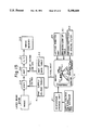
- FIG. 3 is a detailed block diagram of the digital X-ray image processing apparatus shown in FIG. 2.
- reference number 4.1 denotes a PMT supply voltage table for storing conditions of the supply voltage in accordance with the predetermined latitude L
- 4.2 denotes an AMP offset gain table for storing the offset voltage and gain in accordance with the latitude L.
- 2.3 is a determination unit for determining the actual read conditions based on the latitude L to be pointed out by the doctor.
- the latitude L is defined between the minimum intensity of the X-ray Smin and the maximum intensity of the X-ray Smax.
- the minimum intensity Smin and the maximum intensity Smax are input to the PMT supply voltage table 4.1 and the AMP offset gain table 4.2 to obtain optimal voltage and gain of the PMT and AMP.
- FIG. 4 is a schematic block diagram of a digital X-ray image processing apparatus according to a second embodiment of the present invention.
- Reference number 3.2 denotes a pre-scan unit for obtaining a pre-scan histogram from the pre-scan data.
- the pre-scan unit 3.2 is added to the read unit 3.
- the X-ray is irradiated on to the object 3.0 and the X-ray image is accumulated on the photostimulable phosphor plate 3.1. Accordingly, when the pre-scan data is obtained from the accumulated image as previously explained, the pre-scan histogram is calculated in the pre-scan unit 3.2.
- the pre-scan histogram is displayed on the monitor 1.6.
- the latitude L is determined on the pre-scan histogram. Further, based on the latitude L pointed out by the doctor, the photographic conditions are determined from the pre-scan histogram in the determination unit 2.3 as the actual read conditions.
- FIG. 5 is a detailed block diagram of the digital X-ray image processing apparatus shown in FIG. 4.
- reference number 5.1 denotes a pre-scan histogram calculation unit for obtaining the pre-scan histogram from the pre-scan data.
- the pre-scan histogram calculation unit 5.1 is included in the pre-scan unit 3.2 shown in FIG. 4.
- SW denotes a switching unit for switching between the pre-scan operation and the actual scan operation.
- the pre-scan histogram is obtained, and in the position "b", the actual read is performed.
- the pre-scan operation is performed before the actual read operation.
- the pre-scan histogram is displayed on the monitor 1.6.
- FIG. 6 is a schematic block diagram of a digital X-ray image processing apparatus according to a third embodiment of the present invention.
- Reference number 1.7 denotes a second monitor for displaying the pre-scan histogram transmitted from the pre-scan unit 3.2.
- the first and the second monitors are provided on the control console 1.1. Accordingly, it is possible to simultaneously display the standard and the pre-scan histograms on the control console 1.1. Accordingly, the latitude L of the intensity of the X-ray in the pre-scan histogram can be easily defined with reference to the standard histogram.
- noise components are contained in the pre-scan histogram so that it is not possible to determine the latitude in the second monitor 1.7, it is possible to easily point out the latitude on the first monitor 1.6.
- FIG. 7 is a detailed block diagram of the digital X-ray image processing apparatus shown in FIG. 6.
- the switching unit SW is switched to the pre-scan operation so that the pre-scan histogram of the histogram calculation unit 5.1 is output to the second monitor 1.7.
- the latitude L is pointed out on the pre-scan histogram in the second monitor 1.7.
- FIG. 8 is a schematic block diagram of a digital X-ray image processing apparatus according to a fourth embodiment of the present invention.
- reference number 2.2 denotes a correlation analysis unit
- 2.4 denotes a histogram correction unit.
- the correlation analysis unit 2.2 receives the pre-scan and standard histograms, and calculates the correlation value between the standard histogram and the pre-scan histogram to move the standard histogram in the direction of the intensity of the X-ray. Accordingly, it is possible to obtain a maximum correlation value between these histograms.
- the histogram correlation unit 2.4 calculates the difference between the standard histogram and the pre-scan histogram, and correct the latitude of the intensity of the X-ray used for the actual read.
- FIG. 9 is a detailed block diagram of the digital X-ray image processing apparatus shown in FIG. 8.
- the pre-scan histogram H2 is input to the correlation analysis unit 2. Further, the standard histogram H1 is also input to the correlation analysis unit 2.2.
- the correlation analysis unit 2.2 outputs a new latitude L' to determine the photographic conditions to the AMP offset table 4.2 and the PMT supply voltage table 4.1 after calculation of the maximum correlation.
- the correlation value obtained by the correlation analysis unit 2.2 is input to the histogram correction unit 2.4.
- the histogram Hx corrected by the histogram correction unit 24 is stored in the histogram storage unit 2.1.
- the standard histogram stored in the histogram storage unit 2.1 is displayed on the monitor 1.6. The operation of this embodiment is explained in detail below.
- FIG. 10 is diagram for explaining the process of the fourth embodiment.
- the doctor inputs the photographic conditions, for example, the supply voltage, the object data, the purpose of the diagnosis, etc., from the control console 1.1.
- step 1 the histogram having the same photographic conditions as the above is selected from the contents of the standard histogram storage unit 2.1.
- step 2 the selected histogram is displayed on the monitor 1.6 as the standard histogram H1, and the latitude L is pointed out by the doctor.
- step 3 the pre-scan histogram H2 is calculated in the pre-scan histogram calculation unit 5.1, and input to the correlation analysis unit 4.2.
- step 4 the correlation value between the standard histogram H1 and the pre-scan histogram H2 is calculated in the correlation analysis unit 2.2. As shown by arrows, the standard histogram H1 is moved in the direction of the intensity of the X-ray so as to obtain the maximum correlation value.
- step 5 after calculation of the correlation, a new standard latitude L' is determined and displayed on the monitor. This new latitude L' is used for determining the actual read conditions when diagnosing the object.
- step 6 the difference between the standard histogram H1 and the pre-scan histogram H2 is calculated and the configuration of the standard histogram is corrected by the histogram correction unit 2.4.
- step 7 the histogram Hx corrected by the correction unit 2.4 is stored in the standard histogram storage unit 2.1 as the standard histogram.
- FIG. 11 is a view for explaining the maximum correlation value calculated in the correlation analysis unit 2.2 in the fourth embodiment.
- P 0 (x) denotes a probability density function of the standard histogram H1
- P 1 (x) denotes the probability density function of the pre-scan histogram H2.
- m 01 and m 11 denote a first moment
- m 02 and m 12 denote a second moment.
- the subscript "0" denotes the standard histogram and the subscript "1" denotes the pre-scan histogram.
- the "first moment” denotes the center position of the histogram and the "second moment” denotes the latitude.
- the monitor image A shows the probability density function of the standard histogram H1
- the monitor image B shows the probability density function of the standard histogram H2.
- the width of the histogram H2 is broadened in accordance with the ratio of the second moment m 12 /m 02 .
- the maximum correlation value ⁇ 0 is defined by the following formula. ##EQU1##
- the maximum correlation value ⁇ 0 is defined by the difference between the first moments (m 01 -m 11 )
- the latitude L is corrected in accordance with the maximum correlation value ⁇ 0 so that a new latitude L' is pointed out on the histogram H2. That is, the center of the latitude L is shifted by the maximum correlation value ⁇ 0 .
- the shifted new center is defined as the center of the latitude L'.
- the latitude L' is defined by the following formula,
- FIG. 12 is a schematic block diagram of a digital X-ray image processing apparatus according to a fifth embodiment of the present invention.
- the second histogram correction unit 2.5 is used for correcting the standard histogram stored in the histogram storage unit 2.1 based on the actual read histogram.
- the corrected standard histogram is again stored in the histogram storage unit 2.1.
- the actual read is performed for the latitude L on the first standard histogram under the predetermined read conditions, then, the standard histogram is corrected based on the actual read histogram so as to comply with the desired latitude to be diagnosed.
- FIG. 13 is a detailed block diagram of the digital X-ray image processing apparatus shown in FIG. 12.
- the histogram H2 calculated by the histogram calculation unit 5.1 is output to the histogram correction unit 2.5. Further, the standard histogram H1 and the latitude L are input to the histogram correction unit 2.5.
- the corrected histogram Hx (new standard histogram) and new latitude L' from the histogram correction unit 2.5 are stored in the histogram storage unit 2.1. The operation of the fifth embodiment is explained in detail below.
- FIG. 14 is a diagram for explaining the process of the fifth embodiment.
- the doctor inputs the photographic conditions, for example, the object data, the purpose of the diagnosis, etc., from the control console 1.1.
- step 1 the histogram having the same photographic conditions as the above is selected from the contents of the standard histogram storage unit 2.1. instead of the standard histogram H1.
- step 2 the selected histogram is displayed on the monitor 1.6 as the standard histogram H1. Further, the latitude L is pointed out by the doctor. The latitude L is pointed out in the range between the minimum intensity Smin and the maximum intensity Smax.
- step 3 the actual read histogram is obtained by another means for the actual read, and this actual read histogram is output to the histogram correction unit 2.5 to correct the standard histogram previously stored.
- step 4 the corrected actual read histogram is stored in the histogram storage unit 2.1 instead of the standard histogram.
- FIG. 15 is a detailed block diagram of the digital X-ray image processing apparatus according to a sixth embodiment of the present invention.
- reference number 6.1 denotes a gradation look-up table
- 6.2 denotes an emphasis coefficient means of a spacial filter for spacial frequency.
- the data of the gradation look up table 6.1 is input to the monitor 1.6. Further, the emphasis coefficient of the spacial frequency is also input to the monitor 1.6.
- the curve 6.1 denotes a gradation processing curve
- the curve 6.2 denotes an emphasis coefficient curve.
- the gradation and the emphasis coefficient are explained in detail below.
- the gradation curve and the emphasis coefficient curve are displayed on the same histogram. In this case, the histogram pattern is not revised under the above curves, and the conditions of the image processing is revised based on the above curves.
- FIG. 16 is a graph for explaining the conditions of the gradation processing.
- the abscissa denotes the intensity of the X-ray.
- the left side of the ordinate denotes the frequency, and the right side of the ordinate denotes the gradation rate.
- the curves each indicating the conditions of the gradation processing are displayed on the monitor with the standard histogram.
- Reference number 1 is a curve indicating the standard histogram.
- Reference number 2 is a curve indicating the conditions of the gradation processing when the doctor wishes to diagnose the soft portion of the object.
- reference number 3 is a curve indicating the conditions of the gradation processing when the doctor wish to diagnose the whole object, i.e., the bone portion, the soft portion and the skin portion.
- Reference number 4 is a curve indicating the conditions of the gradation processing when the doctor wishes to diagnose the bone portion.
- the standard histogram 1 is not revised in accordance with the gradation processing operation and the conditions of the image processing are changed in accordance with the gradation curve.
- FIG. 17 is a graph for explaining the emphasis coefficient of the spacial frequency.
- the abscissa denotes the intensity of the X-ray.
- the left side of the ordinate denotes the frequency, and the right side of the ordinate denotes the emphasis coefficient of the kernel size of the spacial filter.
- the curves 1 to 3 are displayed on the monitor with the standard histogram.
- Reference number 1 is the curve indicating the standard histogram
- reference numbers 2 and 3 are the curve indicating the emphasis coefficient.
- the standard histogram is not revised in accordance with the spacial frequency and the emphasis coefficient of the kernel size of the spacial filter.
Abstract
A digital X-ray image processing apparatus for exposing an X-ray transmitted through an object onto a photostimulable phosphor plate, for scanning the photostimulable phosphor plate by using an excitation beam to obtain an X-ray image, and for reading the X-ray image. The digital X-ray image processing apparatus includes an image storage unit for storing the X-ray image used for an actual read when diagnosing the object and a histogram storage unit for storing a standard histogram of the X-ray image. The standard histogram is formed by an intensity and frequency of the X-ray. Also provided is a first monitor unit for displaying the standard histogram read out from the histogram storage unit and a read conditions determination unit for determining actual read conditions of the X-ray image based on a latitude of the intensity of the X-ray in the standard histogram.
Description
This application is a continuation of application Ser. No. 70/821,902, filed Jan. 15, 1992, now abandoned, which is a continuation of U.S. application Ser. No. 07/585,630, filed Sep. 20, 1990, also abandoned.
1. Field of the Invention
The present invention relates to a radiograph read apparatus, more particularly, it relates to a digital X-ray image processing apparatus mainly used in the field of medical equipment.
2. Description of the Related Art
An X-ray apparatus is widely used in various fields, particularly in the medical field. Conventionally, as an X-ray apparatus having high sensitivity and high resolution, there is a digital X-ray image processing apparatus displaying an X-ray image on a cathode-ray tube (CRT) instead of a conventional radiograph.
The above conventional digital X-ray image processing apparatus (see, for example, U.S. Pat. No. 3,859,527) uses a photostimulable phosphor plate constituted by a sheet-like fluorescence medium which is able to accumulate a part of the X-ray energy. This fluorescence medium accumulating the X-ray energy is called an "accumulative fluorescence body". The accumulative fluorescence body can accumulate the X-ray energy for a relatively long time.
In general, the digital X-ray image can be obtained by the following steps. That is, when the X-ray is irradiated on to an object, for example, a human body, the X-ray transmitted through the object exposes the photostimulable phosphor plate. When the photostimulable phosphor plate is scanned by an excitation beam (for example, a laser beam), the energy accumulated on the fluorescence body is excited by the laser beam and a fluorescent light corresponding to the accumulated energy is emitted from the photostimulable phosphor plate.
The fluorescent light is collected by collection equipment, for example, bundled optical fibers, and converted to analog electrical signals by an optical-to-electrical converter. Further, the analog electrical signals are converted to digital signals to obtain a digital X-ray image on a monitor display apparatus.
In this case, to determine conditions in an actual reading of the X-ray image from the photostimulable phosphor plate, it is important to previously read an outline of the X-ray image (i.e., the state of the X-ray energy) accumulated on the fluorescence body prior to the actual read (below, "pre-scan").
The "actual read" means, in this case, that a doctor reads the X-ray image displayed on the monitor when diagnosing the object. For the photographic conditions during the actual read, it is necessary to determine a supply voltage for an X-ray tube, a multiplication rate of a photomultiplier, an amplification rate of the amplifier, and a distance between the X-ray tube and the object. In general, this photographic condition data is determined from pre-scan data.
There are some methods for pre-scanning in the conventional art.
In one method, prior to the actual read, the photostimulable phosphor plate is scanned by an excitation beam which is weaker than the excitation beam for the actual read. The quantity of the fluorescent light emitted by the weak excitation beam is measured by suitable measuring equipment so that it is possible to perform the pre-scan prior to the actual read.
In another method, when the X-ray is irradiated onto the photostimulable phosphor plate, a momentary fluorescent light is generated from the photostimulable phosphor plate. In this method, the momentary fluorescent light is measured by suitable measuring equipment so that it is possible to perform the pre-scan prior to the actual read. This method utilizes the characteristic that the intensity of the momentary fluorescent light is proportional to that of the fluorescent light in the actual read.
However, in these methods, much data which is not necessary for the diagnosis, such as a very strong X-ray intensity range and a very weak X-ray intensity range, are contained in the pre-scan data. That is, for example, in the diagnosis of the breast of a human body, although the intensity range of the X-rays for the diagnosis of the lungs is different from that of the X-rays for the diagnosis of ribs, various intensities of the X-rays are mixed in the pre-scan data.
The object of the present invention is to provide a digital X-ray image processing apparatus enabling determination of the optional intensity range of the X-ray in accordance with the object of the diagnosis to increase the precision of the diagnosis.
In accordance with the present invention, there is provided a digital X-ray image processing apparatus for exposing an X-ray transmitted through an object to a photostimulable phosphor plate, for scanning the photostimulable phosphor plate by means of an excitation beam to obtain an X-ray image, and for reading the X-ray image, the digital X-ray image processing apparatus including: an image storage unit for storing the X-ray image used for an actual read when diagnosing the object; a histogram storage unit for storing a standard histogram of the X-ray image, the standard histogram being constituted by an intensity of the X-ray and a frequency thereof; a first monitor unit for displaying the standard histogram read out from the histogram storage unit; and a read conditions determination unit for determining actual read conditions of the X-ray image based on a latitude of the intensity of the X-ray in the standard histogram.
In the preferred embodiment, a digital X-ray image processing apparatus further includes: a switching unit for switching between a pre-scan operation and the actual read operation; and a histogram calculation unit for calculating a pre-scan histogram based on pre-scan data obtained prior to the actual read in the pre-scan operation, and the pre-scan histogram being input to the first monitor means and used instead of the standard histogram.
In the preferred embodiment, a digital X-ray image processing apparatus further includes a second monitor unit for displaying the pre-scan histogram, and the actual read conditions being determined based on the latitude of the intensity of the X-ray in the pre-scan histogram.
In the preferred embodiment, a digital X-ray image processing apparatus further includes: a correlation analysis unit for receiving the pre-scan and standard histograms, and calculating a correlation value to move the standard histogram in the direction of the intensity of the X-ray so as to obtain a maximum correlation value between these histograms; and a histogram correlation unit for calculating a difference between the standard histogram and the pre-scan histogram, and correcting the latitude of the intensity of the X-ray used for the actual read.
In the preferred embodiment, a digital X-ray image processing apparatus, further includes: a gradation look up table for determining conditions of the gradation processing of the standard histogram in accordance with the diagnosis area of the object; and an emphasis coefficient unit for a spacial filter.
In the drawings:
FIG. 1 is a basic structural view of a prior art digital X-ray image processing apparatus;
FIG. 2 is a schematic block diagram of a digital X-ray image processing apparatus according to a first embodiment of the present invention;
FIG. 3 is a detailed block diagram of the digital X-ray image processing apparatus shown in FIG. 2;
FIG. 4 is a schematic block diagram of a digital X-ray image processing apparatus according to a second embodiment of the present invention;
FIG. 5 is a detailed block diagram of the digital X-ray image processing apparatus shown in FIG. 4;
FIG. 6 is a schematic block diagram of a digital X-ray image processing apparatus according to a third embodiment of the present invention;
FIG. 7 is a detailed block diagram of the digital X-ray image processing apparatus shown in FIG. 6;
FIG. 8 is a schematic block diagram of a digital X-ray image processing apparatus according to a fourth embodiment of the present invention;
FIG. 9 is a detailed block diagram of the digital X-ray image processing apparatus shown in FIG. 8;
FIG. 10 is a view for explaining the process of the fourth embodiment shown in FIG. 9;
FIG. 11 is a view for explaining the maximum correlation value calculated in the correlation analysis unit shown in FIG. 9;
FIG. 12 is a schematic block diagram of a digital X-ray image processing apparatus according to a fifth embodiment of the present invention;
FIG. 13 is a detailed block diagram of the digital X-ray image processing apparatus shown in FIG. 12;
FIG. 14 is a view for explaining the process of the fifth embodiment shown in FIG. 12;
FIG. 15 is a detailed block diagram of the digital X-ray image processing apparatus according to a sixth embodiment of the present invention;
FIG. 16 is a view for explaining conditions of the gradation processing; and
FIG. 17 is a view for explaining an emphasis coefficient shown in FIG. 15.
FIG. 1 is a basic structural view of a prior art digital X-ray image processing apparatus. In FIG. 1, reference number 3.1 denotes a photostimulable phosphor plate or mirror, 3.6 an f-θ lens, 3.7 a movable base, 3.8 bundled optical fibers, 3.9 a photomultiplier (PMT), 3.10 an amplifier (AMP), 3.11 an A/D converter (A/D), and 3.12 an image memory.
When the X-ray is irradiated on to the object 3.0 (see, FIG. 2), the X-ray transmitted through the object 3.0 exposes the photostimulable phosphor plate 3.1. When the photostimulable phosphor plate 3.1 is scanned by the excitation beam (for example, laser beam) emitted from the beam source 3.4 through the f-θ lens 3.6, the energy accumulated on the fluorescence body is excited by the laser beam and a fluorescent light corresponding to the accumulated energy is emitted from the photostimulable phosphor plate 3.1.
The movable base 3.7 is used for moving the photostimulable phosphor plate 3.1 to the sub-scanning direction. The fluorescent light is collected by collection equipment, for example, bundled optical fibers 3.8, and converted to the analog electrical signal by the photomultiplier 3.9. Further, the analog electrical signal is multiplied by the photomultiplier 3.9 and converted to digital signals by the A/D converter 3.11 to obtain the digital X-ray image on the CRT or the printer. The digital X-ray image is stored in the image memory 3.12.
FIG. 2 is a schematic block diagram of a digital X-ray image processing apparatus according to a first embodiment of the present invention.
In FIG. 2, reference number 1.1 denotes a control console for controlling the supply voltage and current for an X-ray tube, and an irradiation time of the X-ray above data and a distance between the object and the X-ray tube are transmitted to a control unit 2. 1.2 denotes the X-ray tube, 1.3 denotes an ultrasonic distance meter, and 1.6 denotes a first monitor for displaying the histogram of the X-ray image.
Further, the control unit 2 receives various data output from the control console. 2.1 denotes a standard histogram storage unit for storing various standard histograms, and 2.3 denotes a determination unit for determining read conditions, for example, multiplication rate of the photomultiplier and amplification rate of the amplifier, at the actual read when diagnosing the object.
Still further, reference number 3 denotes a read unit, 3.0 denotes an object, 3.1 denotes a photostimulable phosphor plate, and 3.3 denotes an actual read unit.
The above various data are transmitted to the control unit 2 as the photographic conditions. Further, the distance data is also transmitted to control unit 2. The control unit 2 selects one of the standard histograms in accordance with the above photographic conditions. This selected standard histogram is displayed on the monitor 1.6. The standard histogram is made by estimating a histogram of the X-ray intensity accumulated on the photostimulable phosphor plate 3.1.
In this embodiment, the selected standard histogram indicating the relationship between the intensity of the X-ray (abscissa) and the frequency thereof (ordinate) is displayed on the first monitor 1.6 based on the above photographic conditions. A predetermined latitude of the X-ray intensity is selected on the abscissa of the histogram as the latitude at the actual read. As shown on the monitor 1.6, in the X-ray image of the breast, the frequency of the lungs portion is large, and that of the skin portion is small.
As shown in FIG. 2, the relationship between the X-ray intensity and the frequency thereof is different E among the bone (rib), the lungs, and the skin. Accordingly, when a doctor wishes to diagnose the lungs, the actual read is performed at the above latitude L of the X-ray intensity.
FIG. 3 is a detailed block diagram of the digital X-ray image processing apparatus shown in FIG. 2. In FIG. 3, reference number 4.1 denotes a PMT supply voltage table for storing conditions of the supply voltage in accordance with the predetermined latitude L, and 4.2 denotes an AMP offset gain table for storing the offset voltage and gain in accordance with the latitude L. 2.3 is a determination unit for determining the actual read conditions based on the latitude L to be pointed out by the doctor. In the monitor image 1.6, the latitude L is defined between the minimum intensity of the X-ray Smin and the maximum intensity of the X-ray Smax. The minimum intensity Smin and the maximum intensity Smax are input to the PMT supply voltage table 4.1 and the AMP offset gain table 4.2 to obtain optimal voltage and gain of the PMT and AMP.
FIG. 4 is a schematic block diagram of a digital X-ray image processing apparatus according to a second embodiment of the present invention.
In FIG. 4, the same reference numbers as shown in FIG. 2 are attached to the same components. Reference number 3.2 denotes a pre-scan unit for obtaining a pre-scan histogram from the pre-scan data. In this embodiment, the pre-scan unit 3.2 is added to the read unit 3. The X-ray is irradiated on to the object 3.0 and the X-ray image is accumulated on the photostimulable phosphor plate 3.1. Accordingly, when the pre-scan data is obtained from the accumulated image as previously explained, the pre-scan histogram is calculated in the pre-scan unit 3.2. The pre-scan histogram is displayed on the monitor 1.6. The latitude L is determined on the pre-scan histogram. Further, based on the latitude L pointed out by the doctor, the photographic conditions are determined from the pre-scan histogram in the determination unit 2.3 as the actual read conditions.
FIG. 5 is a detailed block diagram of the digital X-ray image processing apparatus shown in FIG. 4. In FIG. 5, reference number 5.1 denotes a pre-scan histogram calculation unit for obtaining the pre-scan histogram from the pre-scan data. The pre-scan histogram calculation unit 5.1 is included in the pre-scan unit 3.2 shown in FIG. 4.
Further, SW denotes a switching unit for switching between the pre-scan operation and the actual scan operation. In the position "a", the pre-scan histogram is obtained, and in the position "b", the actual read is performed. The pre-scan operation is performed before the actual read operation. The pre-scan histogram is displayed on the monitor 1.6.
FIG. 6 is a schematic block diagram of a digital X-ray image processing apparatus according to a third embodiment of the present invention. Reference number 1.7 denotes a second monitor for displaying the pre-scan histogram transmitted from the pre-scan unit 3.2. In this embodiment, the first and the second monitors are provided on the control console 1.1. Accordingly, it is possible to simultaneously display the standard and the pre-scan histograms on the control console 1.1. Accordingly, the latitude L of the intensity of the X-ray in the pre-scan histogram can be easily defined with reference to the standard histogram. In this embodiment, if noise components are contained in the pre-scan histogram so that it is not possible to determine the latitude in the second monitor 1.7, it is possible to easily point out the latitude on the first monitor 1.6.
FIG. 7 is a detailed block diagram of the digital X-ray image processing apparatus shown in FIG. 6. The switching unit SW is switched to the pre-scan operation so that the pre-scan histogram of the histogram calculation unit 5.1 is output to the second monitor 1.7. The latitude L is pointed out on the pre-scan histogram in the second monitor 1.7.
FIG. 8 is a schematic block diagram of a digital X-ray image processing apparatus according to a fourth embodiment of the present invention. In FIG. 8, reference number 2.2 denotes a correlation analysis unit, and 2.4 denotes a histogram correction unit. The correlation analysis unit 2.2 receives the pre-scan and standard histograms, and calculates the correlation value between the standard histogram and the pre-scan histogram to move the standard histogram in the direction of the intensity of the X-ray. Accordingly, it is possible to obtain a maximum correlation value between these histograms. The histogram correlation unit 2.4 calculates the difference between the standard histogram and the pre-scan histogram, and correct the latitude of the intensity of the X-ray used for the actual read.
FIG. 9 is a detailed block diagram of the digital X-ray image processing apparatus shown in FIG. 8. The pre-scan histogram H2 is input to the correlation analysis unit 2. Further, the standard histogram H1 is also input to the correlation analysis unit 2.2. The correlation analysis unit 2.2 outputs a new latitude L' to determine the photographic conditions to the AMP offset table 4.2 and the PMT supply voltage table 4.1 after calculation of the maximum correlation. The correlation value obtained by the correlation analysis unit 2.2 is input to the histogram correction unit 2.4. The histogram Hx corrected by the histogram correction unit 24 is stored in the histogram storage unit 2.1. The standard histogram stored in the histogram storage unit 2.1 is displayed on the monitor 1.6. The operation of this embodiment is explained in detail below.
FIG. 10 is diagram for explaining the process of the fourth embodiment. First, the doctor inputs the photographic conditions, for example, the supply voltage, the object data, the purpose of the diagnosis, etc., from the control console 1.1.
In step 1, the histogram having the same photographic conditions as the above is selected from the contents of the standard histogram storage unit 2.1.
In step 2, the selected histogram is displayed on the monitor 1.6 as the standard histogram H1, and the latitude L is pointed out by the doctor.
In step 3, the pre-scan histogram H2 is calculated in the pre-scan histogram calculation unit 5.1, and input to the correlation analysis unit 4.2.
In step 4, the correlation value between the standard histogram H1 and the pre-scan histogram H2 is calculated in the correlation analysis unit 2.2. As shown by arrows, the standard histogram H1 is moved in the direction of the intensity of the X-ray so as to obtain the maximum correlation value.
In step 5, after calculation of the correlation, a new standard latitude L' is determined and displayed on the monitor. This new latitude L' is used for determining the actual read conditions when diagnosing the object.
In step 6, the difference between the standard histogram H1 and the pre-scan histogram H2 is calculated and the configuration of the standard histogram is corrected by the histogram correction unit 2.4.
In step 7, the histogram Hx corrected by the correction unit 2.4 is stored in the standard histogram storage unit 2.1 as the standard histogram.
FIG. 11 is a view for explaining the maximum correlation value calculated in the correlation analysis unit 2.2 in the fourth embodiment. In FIG. 11, P0(x) denotes a probability density function of the standard histogram H1, and P1(x) denotes the probability density function of the pre-scan histogram H2. Further, m01 and m11 denote a first moment, and m02 and m12 denote a second moment. The subscript "0" denotes the standard histogram and the subscript "1" denotes the pre-scan histogram. In this case, the "first moment" denotes the center position of the histogram and the "second moment" denotes the latitude.
In FIG. 11, the monitor image A shows the probability density function of the standard histogram H1, and the monitor image B shows the probability density function of the standard histogram H2. As shown in images B and C, the width of the histogram H2 is broadened in accordance with the ratio of the second moment m12 /m02.
The maximum correlation value τ0 is defined by the following formula. ##EQU1##
Accordingly, as shown in image D, the maximum correlation value τ0 is defined by the difference between the first moments (m01 -m11)
As shown in Fig. E, the latitude L is corrected in accordance with the maximum correlation value τ0 so that a new latitude L' is pointed out on the histogram H2. That is, the center of the latitude L is shifted by the maximum correlation value τ0. The shifted new center is defined as the center of the latitude L'. The latitude L' is defined by the following formula,
L'=(m.sub.12 /m.sub.02)×L (2)
FIG. 12 is a schematic block diagram of a digital X-ray image processing apparatus according to a fifth embodiment of the present invention. In this embodiment, the second histogram correction unit 2.5 is used for correcting the standard histogram stored in the histogram storage unit 2.1 based on the actual read histogram. The corrected standard histogram is again stored in the histogram storage unit 2.1. In this case, the actual read is performed for the latitude L on the first standard histogram under the predetermined read conditions, then, the standard histogram is corrected based on the actual read histogram so as to comply with the desired latitude to be diagnosed.
FIG. 13 is a detailed block diagram of the digital X-ray image processing apparatus shown in FIG. 12. The histogram H2 calculated by the histogram calculation unit 5.1 is output to the histogram correction unit 2.5. Further, the standard histogram H1 and the latitude L are input to the histogram correction unit 2.5. The corrected histogram Hx (new standard histogram) and new latitude L' from the histogram correction unit 2.5 are stored in the histogram storage unit 2.1. The operation of the fifth embodiment is explained in detail below.
FIG. 14 is a diagram for explaining the process of the fifth embodiment. First, the doctor inputs the photographic conditions, for example, the object data, the purpose of the diagnosis, etc., from the control console 1.1.
In step 1, the histogram having the same photographic conditions as the above is selected from the contents of the standard histogram storage unit 2.1. instead of the standard histogram H1.
In step 2, the selected histogram is displayed on the monitor 1.6 as the standard histogram H1. Further, the latitude L is pointed out by the doctor. The latitude L is pointed out in the range between the minimum intensity Smin and the maximum intensity Smax.
In step 3, the actual read histogram is obtained by another means for the actual read, and this actual read histogram is output to the histogram correction unit 2.5 to correct the standard histogram previously stored.
In step 4, the corrected actual read histogram is stored in the histogram storage unit 2.1 instead of the standard histogram.
FIG. 15 is a detailed block diagram of the digital X-ray image processing apparatus according to a sixth embodiment of the present invention. In FIG. 15, reference number 6.1 denotes a gradation look-up table, and 6.2 denotes an emphasis coefficient means of a spacial filter for spacial frequency. The data of the gradation look up table 6.1 is input to the monitor 1.6. Further, the emphasis coefficient of the spacial frequency is also input to the monitor 1.6. In the monitor 1.6, the curve 6.1 denotes a gradation processing curve, and the curve 6.2 denotes an emphasis coefficient curve. The gradation and the emphasis coefficient are explained in detail below. In this embodiment, the gradation curve and the emphasis coefficient curve are displayed on the same histogram. In this case, the histogram pattern is not revised under the above curves, and the conditions of the image processing is revised based on the above curves.
FIG. 16 is a graph for explaining the conditions of the gradation processing. In FIG. 16, the abscissa denotes the intensity of the X-ray. The left side of the ordinate denotes the frequency, and the right side of the ordinate denotes the gradation rate.
In this embodiment, the curves each indicating the conditions of the gradation processing are displayed on the monitor with the standard histogram.
FIG. 17 is a graph for explaining the emphasis coefficient of the spacial frequency. In FIG. 17, the abscissa denotes the intensity of the X-ray. The left side of the ordinate denotes the frequency, and the right side of the ordinate denotes the emphasis coefficient of the kernel size of the spacial filter.
In this embodiment, the curves 1 to 3 are displayed on the monitor with the standard histogram. Reference number 1 is the curve indicating the standard histogram, and reference numbers 2 and 3 are the curve indicating the emphasis coefficient. However, the standard histogram is not revised in accordance with the spacial frequency and the emphasis coefficient of the kernel size of the spacial filter.
Claims (5)
1. A digital X-ray image processing apparatus for exposing an X-ray transmitted through an object on to a photostimulable phosphor plate, for scanning the photostimulable phosphor plate by means of an excitation beam to obtain an X-ray image, and for reading the X-ray image, the digital X-ray image processing apparatus comprising:
image storing means for storing the X-ray image used for an actual read when diagnosing the object;
histogram storage means for storing a standard histogram of the X-ray image, a standard histogram being formed by data of the photographic conditions from the X-ray including voltage, current, exposure time and distance of an X-ray tube, conditions of the photographic member including bone, skin, lungs and breasts, and conditions of the object to be X-rayed including thinness or thickness of the object;
first monitor mans for displaying the standard histogram read out from said histogram storage means; and
read conditions determination means for determining actual read conditions of the X-ray image based on a latitude of the intensity of the X-ray in the standard histogram stored in said histogram storage means, without a pre-scanning operation.
2. A digital X-ray image processing apparatus as claimed in claim 1, further comprising:
gradation look up table means for determining conditions of the gradation processing of the standard histogram in accordance with the diagnosis area of the object; and
emphasis coefficient means for spacial filtering, the gradation curve from said gradation look-up tables means, an emphasis coefficient from said emphasis coefficient means, and the standard histogram being simultaneously displayed at said monitor means.
3. A digital X-ray image processing apparatus as claimed in claim 1, further comprising:
a second histogram correction unit, operatively connected to said histogram storage means, for correcting the standard histogram stored in said histogram storage means based on the actual read histogram, and the corrected standard histogram being stored again in said histogram storage means.
4. A digital X-ray image process apparatus as claimed in claim 1, further comprising second monitor means for displaying the pre-scan histogram, and the actual read conditions being determined based on the latitude of the intensity of the X-ray in the pre-scan histogram.
5. A digital X-ray image processing apparatus for exposing an X-ray transmitted through an object onto a photostimulable phosphor plate, for scanning the photostimulable phosphor plate by means of an excitation beam to obtain an X-ray image, and for reading the X-ray image, the digital X-ray image processing apparatus comprising;
image storing means for storing the X-ray image used for an actual read when diagnosing the object;
histogram storage means for storing a standard histogram of the X-ray image, a standard histogram being formed by data of the photographic conditions from the X-ray including voltage, current, exposure time and distance of an X-ray tube, conditions of the photographic member including bond, skin, lungs and breasts, and conditions of the object to be X-rayed including the thinness or thickness of the object;
first monitor means for displaying the standard histogram read out from said histogram storage means;
read conditions determination means for determining actual read conditions of the X-ray image based on a latitude of the intensity of the X-ray in the standard histogram stored in said histogram storage means, without a pre-scanning operation;
switching means for switching between a pre-scan operation and the actual read operation;
a histogram calculation unit, operatively connected to said switching means, for calculating a pre-scan histogram based on a pre-scan data obtained prior to the actual read in the pre-scan operation, the pre-scan histogram being input to said first monitor means and used instead of the standard histogram;
a correlation analysis unit, operatively connected to said histogram storage means and said histogram calculation unit, for receiving the pre-scan and standard histograms, and calculating a correlation value to move the standard histogram in the direction of the intensity of the X-ray to obtain a maximum correlation value between the histograms; and
a histogram correction unit, operatively connected to said correlation analysis unit, for calculating a difference between the standard histogram and the pre-scan histogram, and correcting the latitude of the intensity of the X-ray used for the actual read operation.
Priority Applications (1)
| Application Number | Priority Date | Filing Date | Title |
|---|---|---|---|
| US07/908,915 US5198669A (en) | 1989-09-20 | 1992-07-02 | Digital X-ray image processing apparatus |
Applications Claiming Priority (11)
| Application Number | Priority Date | Filing Date | Title |
|---|---|---|---|
| JP1243635A JPH03107135A (en) | 1989-09-20 | 1989-09-20 | Radiograph information reader |
| JP1-243637 | 1989-09-20 | ||
| JP1243637A JPH03107137A (en) | 1989-09-20 | 1989-09-20 | Radiograph information reader |
| JP1243636A JPH03107136A (en) | 1989-09-20 | 1989-09-20 | Radiograph information reader |
| JP1-243636 | 1989-09-20 | ||
| JP1-243635 | 1989-09-20 | ||
| JP1299753A JPH03160431A (en) | 1989-11-20 | 1989-11-20 | Radiation image information reader |
| JP1-299753 | 1989-11-20 | ||
| US58563090A | 1990-09-20 | 1990-09-20 | |
| US82190292A | 1992-01-15 | 1992-01-15 | |
| US07/908,915 US5198669A (en) | 1989-09-20 | 1992-07-02 | Digital X-ray image processing apparatus |
Related Parent Applications (1)
| Application Number | Title | Priority Date | Filing Date |
|---|---|---|---|
| US70821902 Continuation | 1992-01-15 |
Publications (1)
| Publication Number | Publication Date |
|---|---|
| US5198669A true US5198669A (en) | 1993-03-30 |
Family
ID=27566685
Family Applications (1)
| Application Number | Title | Priority Date | Filing Date |
|---|---|---|---|
| US07/908,915 Expired - Fee Related US5198669A (en) | 1989-09-20 | 1992-07-02 | Digital X-ray image processing apparatus |
Country Status (1)
| Country | Link |
|---|---|
| US (1) | US5198669A (en) |
Cited By (21)
| Publication number | Priority date | Publication date | Assignee | Title |
|---|---|---|---|---|
| US5426684A (en) * | 1993-11-15 | 1995-06-20 | Eastman Kodak Company | Technique for finding the histogram region of interest for improved tone scale reproduction of digital radiographic images |
| WO1995030914A1 (en) * | 1994-05-03 | 1995-11-16 | The Trustees Of The University Of Pennsylvania | Post-processing of mri images |
| US5684888A (en) * | 1993-08-16 | 1997-11-04 | Agfa-Gevaert | Method of monitoring the sensitivity of a system for reading a radiation image stored in a photostimulable phosphor screen |
| US5712482A (en) * | 1996-08-05 | 1998-01-27 | Physics Technology, Inc. | Portable electronic radiographic imaging apparatus |
| US5815591A (en) * | 1996-07-10 | 1998-09-29 | R2 Technology, Inc. | Method and apparatus for fast detection of spiculated lesions in digital mammograms |
| US5917929A (en) * | 1996-07-23 | 1999-06-29 | R2 Technology, Inc. | User interface for computer aided diagnosis system |
| US6018590A (en) * | 1997-10-07 | 2000-01-25 | Eastman Kodak Company | Technique for finding the histogram region of interest based on landmark detection for improved tonescale reproduction of digital radiographic images |
| US6282306B1 (en) * | 1994-09-21 | 2001-08-28 | Canon Kabushiki Kaisha | X-ray image detecting apparatus and image reading apparatus |
| US20020099511A1 (en) * | 2000-12-25 | 2002-07-25 | Fuji Photo Film Co., Ltd. | Scanner and method for setting voltage value of photomultiplier |
| US6518564B1 (en) * | 1998-01-30 | 2003-02-11 | Christof Steiner | Process and device for reading radiation image information stored on an image medium by detecting both the luminescent light emitted and the reflected read out light |
| US20040228510A1 (en) * | 2001-12-28 | 2004-11-18 | Sdgi Holdings, Inc. | Method and device for evaluating the balance forces of the skeleton |
| US20060257005A1 (en) * | 2005-05-11 | 2006-11-16 | Optosecurity Inc. | Method and system for screening cargo containers |
| US20070041613A1 (en) * | 2005-05-11 | 2007-02-22 | Luc Perron | Database of target objects suitable for use in screening receptacles or people and method and apparatus for generating same |
| US20080095463A1 (en) * | 2006-10-19 | 2008-04-24 | Hiroshi Abe | Image Processing Apparatus, Image Acquisition Method and Program |
| US20090080706A1 (en) * | 2007-09-26 | 2009-03-26 | Industry Vision Automation Corporation | Machine imaging apparatus and method for detecting foreign materials |
| US7899232B2 (en) | 2006-05-11 | 2011-03-01 | Optosecurity Inc. | Method and apparatus for providing threat image projection (TIP) in a luggage screening system, and luggage screening system implementing same |
| US7991242B2 (en) | 2005-05-11 | 2011-08-02 | Optosecurity Inc. | Apparatus, method and system for screening receptacles and persons, having image distortion correction functionality |
| US8494210B2 (en) | 2007-03-30 | 2013-07-23 | Optosecurity Inc. | User interface for use in security screening providing image enhancement capabilities and apparatus for implementing same |
| US9632206B2 (en) | 2011-09-07 | 2017-04-25 | Rapiscan Systems, Inc. | X-ray inspection system that integrates manifest data with imaging/detection processing |
| US10302807B2 (en) | 2016-02-22 | 2019-05-28 | Rapiscan Systems, Inc. | Systems and methods for detecting threats and contraband in cargo |
| US10599030B2 (en) * | 2015-03-27 | 2020-03-24 | Duerr Dental Ag | Imaging plate scanner |
Citations (5)
| Publication number | Priority date | Publication date | Assignee | Title |
|---|---|---|---|---|
| US3859527A (en) * | 1973-01-02 | 1975-01-07 | Eastman Kodak Co | Apparatus and method for producing images corresponding to patterns of high energy radiation |
| US4310886A (en) * | 1978-12-26 | 1982-01-12 | Fuji Photo Film, Co. Ltd. | Image gradation processing method and apparatus for radiation image recording system |
| EP0175285A2 (en) * | 1984-09-12 | 1986-03-26 | Fuji Photo Film Co., Ltd. | Radiation image read-out apparatus and reproduction condition designating apparatus |
| US4682028A (en) * | 1984-01-26 | 1987-07-21 | Fuji Photo Film Co., Ltd. | Method of adjusting radiation image read-out conditions |
| US4963739A (en) * | 1988-03-31 | 1990-10-16 | Fuji Photo Film Co., Ltd. | Radiation image read-out apparatus |
-
1992
- 1992-07-02 US US07/908,915 patent/US5198669A/en not_active Expired - Fee Related
Patent Citations (5)
| Publication number | Priority date | Publication date | Assignee | Title |
|---|---|---|---|---|
| US3859527A (en) * | 1973-01-02 | 1975-01-07 | Eastman Kodak Co | Apparatus and method for producing images corresponding to patterns of high energy radiation |
| US4310886A (en) * | 1978-12-26 | 1982-01-12 | Fuji Photo Film, Co. Ltd. | Image gradation processing method and apparatus for radiation image recording system |
| US4682028A (en) * | 1984-01-26 | 1987-07-21 | Fuji Photo Film Co., Ltd. | Method of adjusting radiation image read-out conditions |
| EP0175285A2 (en) * | 1984-09-12 | 1986-03-26 | Fuji Photo Film Co., Ltd. | Radiation image read-out apparatus and reproduction condition designating apparatus |
| US4963739A (en) * | 1988-03-31 | 1990-10-16 | Fuji Photo Film Co., Ltd. | Radiation image read-out apparatus |
Cited By (32)
| Publication number | Priority date | Publication date | Assignee | Title |
|---|---|---|---|---|
| US5684888A (en) * | 1993-08-16 | 1997-11-04 | Agfa-Gevaert | Method of monitoring the sensitivity of a system for reading a radiation image stored in a photostimulable phosphor screen |
| US5426684A (en) * | 1993-11-15 | 1995-06-20 | Eastman Kodak Company | Technique for finding the histogram region of interest for improved tone scale reproduction of digital radiographic images |
| WO1995030914A1 (en) * | 1994-05-03 | 1995-11-16 | The Trustees Of The University Of Pennsylvania | Post-processing of mri images |
| US6282306B1 (en) * | 1994-09-21 | 2001-08-28 | Canon Kabushiki Kaisha | X-ray image detecting apparatus and image reading apparatus |
| US5815591A (en) * | 1996-07-10 | 1998-09-29 | R2 Technology, Inc. | Method and apparatus for fast detection of spiculated lesions in digital mammograms |
| US5917929A (en) * | 1996-07-23 | 1999-06-29 | R2 Technology, Inc. | User interface for computer aided diagnosis system |
| US5712482A (en) * | 1996-08-05 | 1998-01-27 | Physics Technology, Inc. | Portable electronic radiographic imaging apparatus |
| US6018590A (en) * | 1997-10-07 | 2000-01-25 | Eastman Kodak Company | Technique for finding the histogram region of interest based on landmark detection for improved tonescale reproduction of digital radiographic images |
| US6518564B1 (en) * | 1998-01-30 | 2003-02-11 | Christof Steiner | Process and device for reading radiation image information stored on an image medium by detecting both the luminescent light emitted and the reflected read out light |
| US20020099511A1 (en) * | 2000-12-25 | 2002-07-25 | Fuji Photo Film Co., Ltd. | Scanner and method for setting voltage value of photomultiplier |
| US8274061B2 (en) * | 2000-12-25 | 2012-09-25 | Fujifilm Corporation | Scanner and method for setting voltage value of photomultiplier |
| US20040228510A1 (en) * | 2001-12-28 | 2004-11-18 | Sdgi Holdings, Inc. | Method and device for evaluating the balance forces of the skeleton |
| US7361150B2 (en) * | 2001-12-28 | 2008-04-22 | Warsaw Orthopedic, Inc. | Method and device for evaluating the balance forces of the skeleton |
| US7734102B2 (en) | 2005-05-11 | 2010-06-08 | Optosecurity Inc. | Method and system for screening cargo containers |
| US20060257005A1 (en) * | 2005-05-11 | 2006-11-16 | Optosecurity Inc. | Method and system for screening cargo containers |
| US20070041613A1 (en) * | 2005-05-11 | 2007-02-22 | Luc Perron | Database of target objects suitable for use in screening receptacles or people and method and apparatus for generating same |
| US7991242B2 (en) | 2005-05-11 | 2011-08-02 | Optosecurity Inc. | Apparatus, method and system for screening receptacles and persons, having image distortion correction functionality |
| US7899232B2 (en) | 2006-05-11 | 2011-03-01 | Optosecurity Inc. | Method and apparatus for providing threat image projection (TIP) in a luggage screening system, and luggage screening system implementing same |
| US20080095463A1 (en) * | 2006-10-19 | 2008-04-24 | Hiroshi Abe | Image Processing Apparatus, Image Acquisition Method and Program |
| US8078003B2 (en) * | 2006-10-19 | 2011-12-13 | Sony Corporation | Biometric image processing apparatus, biometric image acquisition method, and biometric authentication program |
| US8494210B2 (en) | 2007-03-30 | 2013-07-23 | Optosecurity Inc. | User interface for use in security screening providing image enhancement capabilities and apparatus for implementing same |
| US8351672B2 (en) * | 2007-09-26 | 2013-01-08 | Industry Vision Automation Corp. | Machine imaging apparatus and method for detecting foreign materials |
| US20090080706A1 (en) * | 2007-09-26 | 2009-03-26 | Industry Vision Automation Corporation | Machine imaging apparatus and method for detecting foreign materials |
| US9632206B2 (en) | 2011-09-07 | 2017-04-25 | Rapiscan Systems, Inc. | X-ray inspection system that integrates manifest data with imaging/detection processing |
| US10422919B2 (en) | 2011-09-07 | 2019-09-24 | Rapiscan Systems, Inc. | X-ray inspection system that integrates manifest data with imaging/detection processing |
| US10509142B2 (en) | 2011-09-07 | 2019-12-17 | Rapiscan Systems, Inc. | Distributed analysis x-ray inspection methods and systems |
| US10830920B2 (en) | 2011-09-07 | 2020-11-10 | Rapiscan Systems, Inc. | Distributed analysis X-ray inspection methods and systems |
| US11099294B2 (en) | 2011-09-07 | 2021-08-24 | Rapiscan Systems, Inc. | Distributed analysis x-ray inspection methods and systems |
| US10599030B2 (en) * | 2015-03-27 | 2020-03-24 | Duerr Dental Ag | Imaging plate scanner |
| US10302807B2 (en) | 2016-02-22 | 2019-05-28 | Rapiscan Systems, Inc. | Systems and methods for detecting threats and contraband in cargo |
| US10768338B2 (en) | 2016-02-22 | 2020-09-08 | Rapiscan Systems, Inc. | Systems and methods for detecting threats and contraband in cargo |
| US11287391B2 (en) | 2016-02-22 | 2022-03-29 | Rapiscan Systems, Inc. | Systems and methods for detecting threats and contraband in cargo |
Similar Documents
| Publication | Publication Date | Title |
|---|---|---|
| US5198669A (en) | Digital X-ray image processing apparatus | |
| CA1223980A (en) | Method of adjusting radiation image read-out apparatus | |
| JPH0133818B2 (en) | ||
| US4903205A (en) | Method and apparatus for displaying radiation image, and method and apparatus for calculating unsharp mask signal used for the same | |
| EP0154131B1 (en) | Radiation image read-out and gradation processing method and apparatus | |
| US5369572A (en) | Radiographic image processing method wherein small variation of density is selectively made clear | |
| US6075877A (en) | Method and apparatus of image processing using energy substraction parameters according to thickness of an object | |
| JPH0730815A (en) | X-ray inspection device | |
| JPS62246352A (en) | Digital medical diagnostic imaging apparatus and method | |
| US4578581A (en) | Radiation image read-out method and apparatus | |
| EP0421632B1 (en) | Digital X-ray image processing apparatus and method | |
| US5083024A (en) | Digital x-ray image read apparatus with a correction function | |
| JPH04187142A (en) | Apparatus for switching gradation of radiation image | |
| JP3945976B2 (en) | Image display method and apparatus | |
| US4992664A (en) | Radiation image read-out, processing and reproducing methods | |
| EP0178675B1 (en) | Radiation image read-out apparatus | |
| JP3637049B2 (en) | Dynamic range compression method for radiographic images | |
| JPS63167345A (en) | Reading method for radiation image information | |
| JPS6168031A (en) | Radiation image information reading apparatus | |
| JP2952483B2 (en) | Radiation image information reading and displaying device | |
| JP2791887B2 (en) | Radiation image information reading and displaying device | |
| JPH04314432A (en) | Method and apparatus for photographing and reading radiation image | |
| JPH03107136A (en) | Radiograph information reader | |
| JP3165461B2 (en) | Image processing method, image reading method and image reproducing method | |
| JPH03107137A (en) | Radiograph information reader |
Legal Events
| Date | Code | Title | Description |
|---|---|---|---|
| FEPP | Fee payment procedure |
Free format text: PAYOR NUMBER ASSIGNED (ORIGINAL EVENT CODE: ASPN); ENTITY STATUS OF PATENT OWNER: LARGE ENTITY |
|
| CC | Certificate of correction | ||
| FPAY | Fee payment |
Year of fee payment: 4 |
|
| REMI | Maintenance fee reminder mailed | ||
| LAPS | Lapse for failure to pay maintenance fees | ||
| FP | Lapsed due to failure to pay maintenance fee |
Effective date: 20010330 |
|
| STCH | Information on status: patent discontinuation |
Free format text: PATENT EXPIRED DUE TO NONPAYMENT OF MAINTENANCE FEES UNDER 37 CFR 1.362 |