US5190374A - Method and apparatus for continuously mixing well treatment fluids - Google Patents
Method and apparatus for continuously mixing well treatment fluids Download PDFInfo
- Publication number
- US5190374A US5190374A US07/693,995 US69399591A US5190374A US 5190374 A US5190374 A US 5190374A US 69399591 A US69399591 A US 69399591A US 5190374 A US5190374 A US 5190374A
- Authority
- US
- United States
- Prior art keywords
- water
- polymer
- mixer
- slurry
- mixing
- Prior art date
- Legal status (The legal status is an assumption and is not a legal conclusion. Google has not performed a legal analysis and makes no representation as to the accuracy of the status listed.)
- Expired - Fee Related
Links
- 238000002156 mixing Methods 0.000 title claims abstract description 55
- 238000000034 method Methods 0.000 title claims abstract description 47
- 239000003180 well treatment fluid Substances 0.000 title abstract description 7
- XLYOFNOQVPJJNP-UHFFFAOYSA-N water Substances O XLYOFNOQVPJJNP-UHFFFAOYSA-N 0.000 claims abstract description 127
- 229920000642 polymer Polymers 0.000 claims abstract description 116
- 239000002002 slurry Substances 0.000 claims abstract description 34
- 230000015572 biosynthetic process Effects 0.000 claims abstract description 16
- 238000011282 treatment Methods 0.000 claims abstract description 14
- 238000005507 spraying Methods 0.000 claims abstract description 11
- 150000001875 compounds Chemical class 0.000 claims abstract description 9
- 230000003139 buffering effect Effects 0.000 claims abstract description 8
- 239000000203 mixture Substances 0.000 claims description 21
- 239000002245 particle Substances 0.000 claims description 10
- 239000011248 coating agent Substances 0.000 claims description 8
- 238000000576 coating method Methods 0.000 claims description 8
- 238000007599 discharging Methods 0.000 claims description 7
- 239000007787 solid Substances 0.000 claims description 5
- 239000000375 suspending agent Substances 0.000 claims description 5
- 230000000887 hydrating effect Effects 0.000 claims description 4
- 238000009736 wetting Methods 0.000 claims description 4
- 239000000499 gel Substances 0.000 abstract description 50
- 239000012530 fluid Substances 0.000 description 35
- 239000012141 concentrate Substances 0.000 description 26
- 239000007788 liquid Substances 0.000 description 17
- 229930195733 hydrocarbon Natural products 0.000 description 15
- 238000005755 formation reaction Methods 0.000 description 14
- 150000002430 hydrocarbons Chemical class 0.000 description 14
- 239000004215 Carbon black (E152) Substances 0.000 description 12
- 230000036571 hydration Effects 0.000 description 9
- 238000006703 hydration reaction Methods 0.000 description 9
- 230000008569 process Effects 0.000 description 8
- 239000003349 gelling agent Substances 0.000 description 6
- 239000000654 additive Substances 0.000 description 5
- 230000003750 conditioning effect Effects 0.000 description 5
- 238000010276 construction Methods 0.000 description 5
- 239000000463 material Substances 0.000 description 5
- 239000003795 chemical substances by application Substances 0.000 description 4
- 239000000126 substance Substances 0.000 description 4
- 230000008901 benefit Effects 0.000 description 3
- 239000006172 buffering agent Substances 0.000 description 3
- 230000004044 response Effects 0.000 description 3
- 238000003860 storage Methods 0.000 description 3
- 230000000996 additive effect Effects 0.000 description 2
- 239000000872 buffer Substances 0.000 description 2
- 230000008859 change Effects 0.000 description 2
- 238000004891 communication Methods 0.000 description 2
- 238000013461 design Methods 0.000 description 2
- 230000007613 environmental effect Effects 0.000 description 2
- LEQAOMBKQFMDFZ-UHFFFAOYSA-N glyoxal Chemical compound O=CC=O LEQAOMBKQFMDFZ-UHFFFAOYSA-N 0.000 description 2
- 230000005484 gravity Effects 0.000 description 2
- 230000005764 inhibitory process Effects 0.000 description 2
- 238000012856 packing Methods 0.000 description 2
- 230000003068 static effect Effects 0.000 description 2
- 238000003756 stirring Methods 0.000 description 2
- 238000003466 welding Methods 0.000 description 2
- 241000251468 Actinopterygii Species 0.000 description 1
- 241000157049 Microtus richardsoni Species 0.000 description 1
- ULUAUXLGCMPNKK-UHFFFAOYSA-N Sulfobutanedioic acid Chemical compound OC(=O)CC(C(O)=O)S(O)(=O)=O ULUAUXLGCMPNKK-UHFFFAOYSA-N 0.000 description 1
- 239000012298 atmosphere Substances 0.000 description 1
- 150000001642 boronic acid derivatives Chemical class 0.000 description 1
- 239000004568 cement Substances 0.000 description 1
- 238000006243 chemical reaction Methods 0.000 description 1
- 239000004927 clay Substances 0.000 description 1
- 239000002283 diesel fuel Substances 0.000 description 1
- 239000012895 dilution Substances 0.000 description 1
- 238000010790 dilution Methods 0.000 description 1
- 238000010410 dusting Methods 0.000 description 1
- 230000000694 effects Effects 0.000 description 1
- 229940015043 glyoxal Drugs 0.000 description 1
- 125000001183 hydrocarbyl group Chemical group 0.000 description 1
- 230000002209 hydrophobic effect Effects 0.000 description 1
- 230000002706 hydrostatic effect Effects 0.000 description 1
- 239000004615 ingredient Substances 0.000 description 1
- 239000003112 inhibitor Substances 0.000 description 1
- 238000004519 manufacturing process Methods 0.000 description 1
- 238000012986 modification Methods 0.000 description 1
- 230000004048 modification Effects 0.000 description 1
- 230000021715 photosynthesis, light harvesting Effects 0.000 description 1
- 229920000058 polyacrylate Polymers 0.000 description 1
- 229920002959 polymer blend Polymers 0.000 description 1
- 238000002360 preparation method Methods 0.000 description 1
- 238000005086 pumping Methods 0.000 description 1
- 230000003134 recirculating effect Effects 0.000 description 1
- 238000011084 recovery Methods 0.000 description 1
- 230000000717 retained effect Effects 0.000 description 1
- 239000004576 sand Substances 0.000 description 1
- 238000012163 sequencing technique Methods 0.000 description 1
- 238000004513 sizing Methods 0.000 description 1
- 239000000344 soap Substances 0.000 description 1
- 239000000243 solution Substances 0.000 description 1
- 239000002904 solvent Substances 0.000 description 1
- 125000006850 spacer group Chemical group 0.000 description 1
- 238000004381 surface treatment Methods 0.000 description 1
- 239000004094 surface-active agent Substances 0.000 description 1
- 230000008961 swelling Effects 0.000 description 1
- 239000011800 void material Substances 0.000 description 1
Images


Classifications
-
- B—PERFORMING OPERATIONS; TRANSPORTING
- B01—PHYSICAL OR CHEMICAL PROCESSES OR APPARATUS IN GENERAL
- B01F—MIXING, e.g. DISSOLVING, EMULSIFYING OR DISPERSING
- B01F33/00—Other mixers; Mixing plants; Combinations of mixers
- B01F33/80—Mixing plants; Combinations of mixers
-
- B—PERFORMING OPERATIONS; TRANSPORTING
- B01—PHYSICAL OR CHEMICAL PROCESSES OR APPARATUS IN GENERAL
- B01F—MIXING, e.g. DISSOLVING, EMULSIFYING OR DISPERSING
- B01F25/00—Flow mixers; Mixers for falling materials, e.g. solid particles
- B01F25/70—Spray-mixers, e.g. for mixing intersecting sheets of material
- B01F25/72—Spray-mixers, e.g. for mixing intersecting sheets of material with nozzles
- B01F25/721—Spray-mixers, e.g. for mixing intersecting sheets of material with nozzles for spraying a fluid on falling particles or on a liquid curtain
-
- E—FIXED CONSTRUCTIONS
- E21—EARTH DRILLING; MINING
- E21B—EARTH DRILLING, e.g. DEEP DRILLING; OBTAINING OIL, GAS, WATER, SOLUBLE OR MELTABLE MATERIALS OR A SLURRY OF MINERALS FROM WELLS
- E21B21/00—Methods or apparatus for flushing boreholes, e.g. by use of exhaust air from motor
- E21B21/06—Arrangements for treating drilling fluids outside the borehole
- E21B21/062—Arrangements for treating drilling fluids outside the borehole by mixing components
-
- E—FIXED CONSTRUCTIONS
- E21—EARTH DRILLING; MINING
- E21B—EARTH DRILLING, e.g. DEEP DRILLING; OBTAINING OIL, GAS, WATER, SOLUBLE OR MELTABLE MATERIALS OR A SLURRY OF MINERALS FROM WELLS
- E21B43/00—Methods or apparatus for obtaining oil, gas, water, soluble or meltable materials or a slurry of minerals from wells
- E21B43/25—Methods for stimulating production
- E21B43/26—Methods for stimulating production by forming crevices or fractures
- E21B43/2607—Surface equipment specially adapted for fracturing operations
-
- E—FIXED CONSTRUCTIONS
- E21—EARTH DRILLING; MINING
- E21B—EARTH DRILLING, e.g. DEEP DRILLING; OBTAINING OIL, GAS, WATER, SOLUBLE OR MELTABLE MATERIALS OR A SLURRY OF MINERALS FROM WELLS
- E21B43/00—Methods or apparatus for obtaining oil, gas, water, soluble or meltable materials or a slurry of minerals from wells
- E21B43/25—Methods for stimulating production
- E21B43/26—Methods for stimulating production by forming crevices or fractures
- E21B43/27—Methods for stimulating production by forming crevices or fractures by use of eroding chemicals, e.g. acids
Landscapes
- Engineering & Computer Science (AREA)
- Life Sciences & Earth Sciences (AREA)
- Mining & Mineral Resources (AREA)
- Geology (AREA)
- Physics & Mathematics (AREA)
- Chemical & Material Sciences (AREA)
- Environmental & Geological Engineering (AREA)
- Fluid Mechanics (AREA)
- Chemical Kinetics & Catalysis (AREA)
- General Life Sciences & Earth Sciences (AREA)
- Geochemistry & Mineralogy (AREA)
- General Chemical & Material Sciences (AREA)
- Mechanical Engineering (AREA)
- Processing And Handling Of Plastics And Other Materials For Molding In General (AREA)
Abstract
An apparatus and method for continuously mixing well treatment fluids, such as fracturing gels and the like. Dry polymer is fed into a metering feeder which accurately meters the rate of polymer fed into a water spraying mixer. A vent is provided so that air can enter with the polymer as necessary. Water, with or without a buffering compound therein, is flowed through a water inlet of the mixer. The water is jetted into a spiraling flow pattern through which the polymer falls and is substantially wetted. Auxiliary water inlets may be used to add additional water to the water-polymer slurry to increase mixing energy and increase the amount of slurry produced. The slurry is discharged into a mixing tank with an agitator and then into a holding tank. The slurry may also pass through a shear device to further increase the rate of viscosification of the slurry. In this way, the slurry may be continuously mixed on a real time basis while carrying out the well treatment operation, such as the fracturing of a formation.
Description
1. Field Of The Invention
The present invention relates to mixing of polymer gel agents and water to form a well treatment fluid, such as a fracturing ("frac") gel or other similar gel, and more particularly, to a method and apparatus for continuously mixing such gels on a real time basis to achieve rapid hydration without the necessity of an oil-based fluid or the suspension agents normally associated therewith.
2. Description Of The Prior Art
Many treatments and procedures are carried out in industry utilizing high viscosity fluids to accomplish a number of purposes. For example, in the oil industry, high viscosity aqueous well treating fluids or gels are utilized in treatments to increase the recovery of hydrocarbons from subterranean formations, such as by creating fractures in the formation, acidizing the formations, etc. High viscosity aqueous fluids are also commonly utilized in well completion procedures. For example, during the completion of a well, a high viscosity aqueous completion fluid having a high density is introduced into the well to maintain hydrostatic pressure on the formation which is higher than the pressure exerted by the fluids contained in the formation, thereby preventing the formation fluids from flowing into the well bore.
High viscosity treating fluids, such as fracturing or acidizing gels, are normally made using dry polymer additives or agents which are mixed with water or other aqueous fluids at the job site. Such mixing procedures have some inherent problems, particularly on remote sites or when large volumes are required. For example, special equipment for mixing the dry additives with water is required, and problems such as chemical dusting, uneven mixing, lumping of gels while mixing and extended preparation and mixing time are involved. In addition, the mixing and physical handling of large quantities of dry chemicals require a great deal of manpower, and when continuous mixing is required, the accurate and efficient handling of dry chemicals is extremely difficult.
The lumping of gels occurs because the initial contact of the polymer with water results in a very rapid hydration of the outer layer of particles which creates a sticky, rubbery exterior layer that prevents the interior particles from contacting water. The net effect is formation of what are referred to as "gel balls" or "fish eyes". These hamper efficiency by lowering the viscosity achieved per pound of gelling agent and also by creating insoluble particles that can restrict flow both into the well formation and back out of it. Thus, simply mixing the untreated polymer directly with water is not a very successful method of preparing a smooth homogeneous gel free from lumps. A method directed to solving this problem is to control particle size and provide surface treatment modifications to the polymer. It is desired to delay hydration long enough for the individual polymer particles to disperse and become surrounded by water so that no dry particles are trapped inside a gelled coating to form a gel ball. This can be achieved by coating the polymer with materials such as borate salts, glyoxal, non-lumping HEC, sulfosuccinate, metallic soaps, surfactants, or other materials of opposite surface charge to the polymer.
One way to improve the efficiency of polymer addition to water and derive the maximum yield from the polymer is to prepare a stabilized polymer slurry (SPS), also referred to as a liquid gel concentrate (LGC). The liquid gel concentrate is premixed and then later added to the water. In U.S. Pat. No. 4,336,145 to Briscoe, assigned to the assignee of the present invention, a liquid gel concentrate is disclosed comprising water, the polymer or polymers, and an inhibitor having the property of reversibly reacting with the hydratable polymer in a manner wherein the rate of hydration of the polymer is retarded. Upon a change in the Ph condition of the concentrate such as by dilution and/or the addition of a buffering agent (Ph changing chemical) to the concentrate, upon increasing the temperature of the concentrate, or upon a change of other selected condition of the concentrate, the inhibition reaction is reversed, and the polymer or polymers hydrate to yield the desired viscosified fluid. This reversal of the inhibition of the hydration of the gelling agent in the concentrate may be carried out directly in the concentrate or later when the concentrate is combined with additional water.
The aqueous-based liquid gel concentrate of Briscoe has worked well at eliminating gel balls and is still in routine use in the industry. However, aqueous concentrates can suspend only a limited quantity of polymer due to the physical swelling and viscosification that occurs in a water-based medium. Typically about 0.8 pounds of polymer can be suspended per gallon of the concentrate.
By using a hydrocarbon carrier fluid, rather than water, higher quantities of solids can be suspended. For example, up to about five pounds per gallon of polymer may be suspended in a diesel fuel carrier. Such a liquid gel concentrate is disclosed in U.S. Pat. No. 4,722,646 to Harms and Norman, assigned to the assignee of the present invention. Such hydrocarbon-based liquid gel concentrates work well but require a suspension agent such as an organophylic clay or certain polyacrylate agents. The hydrocarbon-based liquid gel concentrate is later mixed with water in a manner similar to that for aqueous-based liquid gel concentrates to yield a viscosified fluid, but hydrocarbon-based concentrates have the advantage of holding more polymer.
An additional problem with prior methods using liquid gel concentrates occurs in offshore situations. The service vessels utilized to supply the offshore locations have a limited storage capacity and must therefore often return to port for more concentrate before they are able to do additional jobs, even when the liquid gel concentrate is hydrocarbon-based. Therefore, it would be desirable to be able to continuously mix a well treatment gel during the actual treatment of the subterranean formation from dry ingredients. For example, such an on-line system could satisfy the fluid flow requirements for large hydraulic fracturing jobs during the actual fracturing of the subterranean formation by continuously mixing the fracturing gel.
One method and apparatus for continuously mixing a fracturing gel is disclosed in U.S. Pat. No. 4,828,034 to Constien et al., in which a fracturing fluid slurry concentrate is mixed through a static mixer device on a real time basis to produce a fully hydrated fracturing fluid during the actual fracturing operation. This process utilizes a hydrophobic solvent which is characterized by a hydrocarbon such as diesel as in the hydrocarbon-based liquid gel concentrates described above.
Recently, however, there have been some problems with hydrocarbon-based liquid gel concentrates because some well operators object to the presence of these fluids, such as diesel, even though the hydrocarbon represents a relatively small amount of the total fracturing gel once mixed with water. Also, there are environmental problems associated with the clean-up and disposal of well treatment gels containing hydrocarbons. These hydrocarbon-related problems would also apply to the process of Constien et al. Accordingly, there is a need for a process to produce a well treatment gel in which relatively higher amounts of polymer per unit volume can be utilized while eliminating the environmental problems and objections related to hydrocarbon-based concentrates. There is also a need for this process to produce the well treatment gel substantially continuously during the well treatment operation to overcome the storage capacity problems discussed above.
The method and apparatus of the present invention provide a solution to these problems by providing a means for substantially continuously producing a fracturing gel without the use of hydrocarbons or suspension agents, while still avoiding gel balls, by feeding the polymer into an axial flow mixer which has high mixing energy to substantially wet all of the polymer during its initial contact with water. After initial mixing, additional water may be added to the mixer to increase the volume of water-polymer slurry produced thereby.
In the present invention, it is possible to use a non-coated (non-surface-treated) gelling agent. This provides a simpler and less expensive process, and the materials themselves are also cheaper because raw gelling agents are less expensive than coated or treated materials.
The apparatus and method of the present invention provide for real time mixing of well treatment fluids, such as fracturing gels, acidizing gels, fracture-acidizing gels, gravel packing gels, weighted gels, or the like, from powdered polymer solids in real time. This on-line system may be used in oil field applications and eliminates conventional large volume mixing tanks yet satisfies the fluid flow requirements for well treatment processes such as large hydraulic fracturing jobs during the actual fracturing of the subterranean formation. With the present invention, full hydration of the polymer and optimum viscosity of the well treatment fluid may be achieved in a relatively short time while avoiding the formation of gel balls.
The preferred method of hydrating a polymer to produce a well treatment fluid or gel comprises the steps of providing a predetermined quantity of the hydratable polymer in a substantially particulate form to a polymer or solids inlet of a water spraying mixer, supplying a stream of water to a water inlet of the mixer, and mixing the polymer in water in the mixer, thereby wetting substantially all of the solid polymer particles to form a water-polymer mix prior to discharge from the mixer. The step of providing a predetermined quantity of polymer preferably comprises adding bulk polymer to a metering feeder and accurately supplying the predetermined quantity of polymer from the feeder to the mixer. The metering feeder preferably comprises a metering auger which rotates at a controlled speed, thereby discharging the predetermined quantity of polymer therefrom at the desired rate.
The polymer particles may be treated with a hydration-delaying coating, in which case the method further comprises the step of adding a buffering compound or other suitable agent to the stream of water for chemically reversing the coating. Preferably, the buffering compound is added to the stream of water prior to entry of the stream of water into the water spraying mixer. This eliminates the previously known step of mixing the buffering agent with a previously dispersed gelling agent. Thus, in this embodiment, the method of hydrating a polymer of the present invention may be said to comprise the steps of supplying a quantity of coated polymer to a mixer, supplying a quantity of buffered water to the mixer for substantially completely wetting the coated polymer, and discharging the wetted water-polymer mix or slurry from the mixture substantially without lumping. A step of supplying an additional quantity of buffered water to the mixer after initial contact of the coated polymer with the first mentioned quantity of buffered water may be added, thereby increasing the volume of the mixture.
Supplying the polymer preferably comprises the steps of feeding bulk polymer to the metering feeder, and discharging an accurately controlled predetermined quantity of polymer from the feeder to the mixer. The polymer may be supplied without a suspension agent.
The method of the present invention further comprises flowing the slurry or mix through a high shear device after it is discharged from the mixer for increasing the rate of viscosification of the mix.
The method may also comprise the step of providing an air inlet opening for preventing formation of a vacuum in the feeder.
The method may further comprise discharging the water-polymer mix from the mixer into a tank and agitating the mix in the tank.
The apparatus of the present invention in a preferred embodiment comprises the metering feeder, the discharge of which is connected to the polymer inlet of the mixer. This connection may be made by a tee wherein one of the tee connections is left open so that air can enter the system. A water supply is connected by a water line to the water inlet of the mixer. The buffer may be injected into this water line. The mixer is preferably mounted adjacent to the upper portion of a mixing or primary tank, and an agitator may be provided in the mixing tank to further agitate and stir the slurry. The slurry may be transferred from the mixing tank to a holding or secondary tank after which it is discharged to the fracturing process. The high shear device may be disposed in the holding tank. A pump may be used for transferring the slurry from the mixing tank to the holding tank.
One embodiment of the water spraying mixer is an axial flow mixer substantially identical to that disclosed in prior U.S. patent application Ser. No. 07/412,255, assigned to the assignee of the present invention and incorporated herein by reference. This prior art mixer has been used for mixing cement, and in this embodiment, two additional ports in the mixer are used for recirculating the slurry. In the present invention, these ports are used as additional inlets branched from the main water line, thereby providing a means for directing additional water to the mixer after the polymer is first contracted by water in the mixer. This increases the mixing energy within the mixer and provides an increased volume of water-polymer mix.
The mixer comprises a valve means for controlling the amount of water entering the mixer through the main water inlet and further comprises a means for directing the water in a substantially spiralling flow which wets the polymer as it falls through the mixer.
It is an important object of the present invention to provide a method of rapid hydration of polymer when the polymer is added to water to produce a viscous well treatment fluid, such as a fracturing gel, gravel packing fluid, viscous acidizing gel, or similar fluid.
It is another object of the invention to provide a method of rapid hydration of polymer in producing a viscous fluid in an on-line real time basis by continuously producing the fluid during a well treatment process.
It is an additional object of the invention to provide a method and apparatus of producing a viscous fluid such as fracturing gel while eliminating the need to batch-mix the polymer in large volume tanks, although the method can be used to prepare batches of gel to be held in storage tanks.
It is a further object of the invention to provide a method and apparatus for producing a fracturing gel and eliminate the formation of gel balls without requiring the production of an aqueous-based or hydrocarbon-based liquid gel concentrate.
Still another object of the invention is to provide a method and apparatus for mixing a polymer with water utilizing a water spraying mixer.
Another object of the invention is to provide a method and apparatus for rapidly hydrating a non-coated or non-surface treated gelling agent without necessarily adding a buffering agent.
Additional objects and advantages of the invention will become apparent as the following detailed description of the preferred embodiment is read in conjunction with the drawings which illustrate such preferred embodiment.
FIG. I presents a schematic of the apparatus of the present invention for continuously mixing polymers with water.
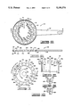
FIG. 2 is a partially cross-sectional and partially elevational view of the water spraying mixer used in the present invention.
FIG. 3 is a plan view of an orifice plate of a valve of the mixer shown in FIG. 2.
FIG. 4 is a cross-sectional view taken along lines 4--4 in FIG. 3.
FIG. 5 is a plan view of a valve plate of the valve of the mixer.
FIG. 6 is a cross-sectional view taken along lines 6--6 in FIG. 5.
FIG. 7 is a plan view of a water jet member of the valve of the water spraying mixer.
FIG. 8 is a cross section taken along lines 8--8 in FIG. 7.
FIG. 9 is a cross-sectional view of a corner of the water jet member taken along lines 9--9 in FIG. 7.
FIG. 10 presents a cross section of a part of the water jet member taken along lines 10--10 in FIG. 7.
FIG. 11 is a plan view of a diffuser of the mixer shown in FIG. 2.
Referring now to the drawings, and more particularly to FIG. 1, the apparatus for continuously mixing well treatment gels or similar fluids of the present invention is shown and generally designated by the numeral 10.
The polymer is introduced into the system by pouring it in bulk form into a hopper portion 14 of a feeder 16. Feeder 16 is preferably of a type which discharges an accurately metered quantity of polymer over time. The feeder illustrated is a metering feeder, such as an Acrison feeder. It should be understood, however, that the invention is not intended to be limited to this particular Acrison feeder. The important feature is that a device be used which provides an accurately metered quantity of polymer discharged therefrom.
The Acrison feeder has a large conditioning auger or agitator 18 adjacent to the bottom of hopper 14. Conditioning auger 18 of this prior art feeder "conditions" or stirs the polymer and breaks up any clumps of polymer that might be stuck together. After being stirred by conditioning auger 18, the polymer falls through an opening 20 into a feed chamber 22. A smaller metering auger 23 rotates within chamber 22, and the polymer is discharged from feeder 16 through an outlet 24. In the Acrison feeder, conditioning auger 18 and metering auger 23 rotate at dissimilar speeds. A control box 26 drives conditioning auger 18 and metering auger 23. A speed transducer 28 may be engaged with control box 26.
A water line 42 is connected to a water inlet 114 of mixer 38. Water line 42 may include a flow meter 44, such as a Halliburton turbine flow meter. Water line 42 is also connected by branches 46 and 48 to additional or auxiliary water inlets 206 and 208, respectively. Water may be supplied to water line 42 from a water tank or reservoir 50, or the water supply may be connected directly to the water line. A pump 51 may be used to pump from reservoir 50 as necessary.
A buffering compound or any other desired additive may also be introduced to water line 42 through a metering means 52. A pump 53 may be used as necessary to pump the buffering compound or other additive. When a buffer is required, the compound preferably is thus introduced or injected directly into the system with the water.
A controller 55 may be connected to speed transducer 28, flow meter 44, and pumps 51 and 53, thus providing a feedback means for controlling the flow rates of the polymer, water and any buffering compound or other additives. In this way, the polymer/water concentration and throughput are controlled.
The slurry is discharged from mixing tank 54 through an outlet 58 and flows through a slurry line 60 to inlet 62 of a holding tank 64. Holding tank 64 may also be referred to as secondary tank 64. The slurry may flow by gravity, but generally, a pumping means, such as centrifugal pump 66 will be installed in slurry line 60 to move the slurry. Pump 66 may also be described as a shear device 66 which applies shear to the fluid.
In one embodiment, the fluid passes through another shear device 68. It is well known that applying shear to the fluid will increase hydration and reduce the time necessary for the fluid to reach its maximum viscosity. Therefore, when time is a critical factor, shear device 66 and/or 68 may be necessary. The slurry will eventually reach its maximum viscosity after a certain period of time anyway, and if time is not critical, such as when the fluid is held for a lengthy period in holding tank 64, then shear devices 66 and/or 68 may be eliminated. Shear device 68 may be any device which provides a high shear to the fluid. Examples of such high shear devices include, but are not limited to, centrifugal pumps, rotating turbine paddles, static flow mixers or the like. These devices may be used singly, in series, and/or in combination.
The fluid is discharged from holding tank 64 through an outlet 70, and the fluid then flows to other devices known in the art and then to the well. For example, fluid flowing from outlet 70 of holding tank 64 may enter a fracturing blender which mixes sand with the slurry. Such downstream devices are known in the art and are therefore not illustrated in FIG. 1.
Referring now to FIG. 2, the details of water spraying mixer 38 will be discussed. This description of mixer 38 is substantially the same as that presented in prior U.S. patent application Ser. No. 07/412,255 which has already been incorporated herein by reference. Mixer 38 is illustrated as an axial flow device which conveys the polymer axially from the inlet to the outlet thereof. That is, there are no elbows or horizontal conduits through which the polymer must be conveyed during its mixing with water prior to being discharged into mixing tank 54.
The mixing water, as it exits orifice plate 146, flows in an axial direction and is subsequently turned and directed toward the polymer flow path coming from sleeve 134. This turning of the water flow direction is produced by the jet means 150 which in the preferred embodiment has grooves coinciding with the orifice plate 146 orifices. Thus, jet means 150 changes the direction of the mixing water from axially downward to slightly tangential and downward. This produces a downwardly spiraling column of fluid circulating about an open center or iris. In a preferred embodiment, the depths of the grooves of jet means 150 are staggered so that with high flow rates, backflow up passage 138 is prevented.
Referring now also to FIGS. 3 and 4, orifice plate 146 includes an annular member 152 having a central opening 153 defined by an inner periphery 154 about which the plurality of orifices 156 is defined. The orifices of the preferred embodiment include three sets of differently sized orifices 156a, 156b, 156c. Each set includes six orifices of the same size. In the illustrated embodiment, the orifices 156a have the smallest diameter, orifices 156b have a larger diameter, and the orifices 156c have the largest diameter of the three sets. These are spaced sequentially and equiangularly around the inner periphery 154 as best seen in FIG. 3. The orifices can be the same size or of different sizes and different arrangements.
Also defined about inner periphery 154 is a notch or shoulder defined by an annular surface 158 and an adjoining, perpendicularly extending cylindrical surface 160.
When orifice plate 146 is connected to water inlet manifold 114 by the retaining bolts 166, orifices 156 are disposed below exit port 124 of water inlet manifold 114. Orifice plate 146 is also concentrically disposed about inlet sleeve 134. A seal ring 168 seals orifice plate 146 and inlet sleeve 134. Thus, orifice plate 146 is disposed below and adjacent to valve plate 148.
The disposition of valve plate 148 concentrically about inlet sleeve 134 adjacent to exit port 124 of water inlet manifold 114 is shown in FIG. 2. As disposed, valve plate 148 is pivotably connected to orifice plate 146 so that the position to which valve plate 148 is pivoted determines which of orifices 156 are open to pass liquid. The overall construction of valve plate 148 is more clearly shown in FIGS. 5 and 6. The preferred embodiment of valve plate 148 includes a ring 170 from which an actuating arm 172 extends radially outwardly. Arm 172 can be engaged by a suitable actuating device (not shown).
The sets of orifices 156a, 156b, 156c are progressively opened as actuating arm 172 of valve plate 148 is moved clockwise for the orientation shown in FIG. 5 or into the page for the orientation shown in FIG. 2. This direction of rotation is limited when actuating arm 172 abuts the corresponding bolt 166. Opening of an orifice 156a, 156b, 156c occurs when a corresponding aperture or space 176a, 176b, 176c defined between teeth 174a, 174b, 174c overlies or registers with the respective orifice of inner periphery 154 of orifice plate 146. Thus these elements of valve plate 148 define means for simultaneously opening orifices 156a, 156b, 156c of a respective set in response to pivotation of valve plate 148. In the preferred embodiment, the sequence of opening orifices 156 is such that an overlap exists. For example, the set of orifices 156b starts to open before the set of orifices 156a is fully open. This overlap makes the flow area versus position much smoother, and it can be made to approximate a straight line response if desired.
Within the body of ring 170 there are defined two grooves 178 and 180. Groove 178 is in a surface of ring 170 facing orifice plate 146, and groove 180 is in a surface of ring 170 facing opposite or away from orifice plate 146. These receive seals, such as O- rings 182 and 184, respectively, as shown in FIG. 2 to seal against the top surface of orifice plate 146 and the bottom surface of water inlet manifold 114, respectively. Seal groove 180 has a greater diameter than seal groove 178, thus the groove 180 encompasses a greater area of valve plate 148 than is encompassed by groove 178. The pressure which exists during operation acts on the greater upper surface area of valve plate 148 sealed by seal 184 to bias valve plate 148 downwardly against orifice plate 146, thereby minimizing leakage between orifice plate 146 and valve plate 148.
The above-described orifice plate 146 and valve plate 148 are designed in the preferred embodiment to provide a valve through which fluid can be flowed at a constant velocity for different volumetric flow rates. As used herein, "constant velocity" does not mean absolutely no velocity difference, but rather the term encompasses small velocity differences which are not significant for practical purposes to which the invention is put.
As shown in FIG. 2, liquid jet means 150 is disposed adjacent to bottom end 142 of inlet sleeve 134 and in communication with orifice plate 146. Liquid jet means 150 directs water into a circulating flow path as the water from inlet manifold 114 is passed through orifice plate 146 so that the downward flow of the polymer from polymer inlet sleeve 134 mixes with the water in the circulating flow.
In the preferred embodiment of jet means 150 shown in FIGS. 2 and 7-10, the circulating flow is caused by the construction of jet means 150 which includes an axial body 188 having a plurality of grooves 198 defined therein for directing streams of the water exiting orifices 156 with which apertures 176 of valve plate 148 register so that the directed streams form a flow circulating about an axis 190 of axial body 188. See FIG. 8. Axis 190 is aligned with the axis of inlet sleeve 134 so that axial body 188 is coaxially related to inlet sleeve 134. This relationship is maintained, and axial body 188 is connected to the previously described assembly of mixer 38, by means of a retaining collar 192 having a flange 194 which carries an O-ring 195 and through which retaining bolts 166 extend as shown in FIG. 2.
Grooves 198 defined in interior surface 196 are of three sizes and orientations to correspond to the orifices 156a, 156b and 156c overlaying and aligned and registering with the grooves. The grooves of these three sets are respectively identified by the reference numerals 198a, 198b, 198c. The shape of each of these is more clearly shown in FIGS. 8-10. Each of the grooves is formed at an angle to a radius of the cylindrical shape of axial body 188. Each group of grooves 198 angles downwardly from a semicircular opening at the top in a manner which is oblique to axis 190. In a preferred embodiment, the groove depths are staggered in sequential sets wherein each of three grooves within a set extends to a different depth (e.g., sequentially deep, deeper, deepest). With high flow rates, this prevents backflow up passage 138 15 resulting from flow interference.
As a result of the orientation of grooves 198, the water received by the grooves is not angled directly downwardly or at axis 190; rather, the water is directed at an angle as indicated by arrows 200c, 200b, 200c in FIG. 7. The result of this angular directing of the flow is to create a downwardly spiraling flow as indicated by the arrow 202 in FIG. 7. This forms a void 204, sometimes referred to as an iris, about axis 190.
As a result of the aforementioned construction and operation of orifice plate 146, valve plate 148 and liquid jet means 150, valve 144 has a reduced susceptibility to clogging by particles in the mix water, it has a relatively fast opening response time, and it can be tailored to achieve different gains via the different orifice sizes in orifice plate 146. This construction and operation also provides a single source of water control which permits easier manual or automatic control (i.e., only valve plate 148 needs to be operated for water control). It also communicates more water energy from the same size pumps which have been used with prior systems. The downwardly spiraling flow created within jet means 150, wherein open iris 204 is formed, helps separate entrained air from the water/polymer mixture and helps break up the polymer.
As further shown in FIG. 2, additional or auxiliary inlets 206 and 208 of mixer 38 are characterized as inlet sleeves 206 and 208 which are substantially diametrically opposed and skewed towards the same direction as water jetting grooves 198 of jet means 150. That is, as illustrated in FIG. 2 inlet sleeves 206 and 208 are disposed in a downward direction and at a slightly tangential angle to create a circular flow pattern. Thus, the water flowing through inlet sleeves 206 and 208 enters the circulating flow below jet means 150 in the same direction of circulation. Inlet sleeves 206 and 208 are connected to axial body 188 of jet means 150 by a containment body or housing 210 as shown in FIG. 2. Containment body 210 extends below jet means 150.
The use of at least two additional or auxiliary inlets 206 and 208 allows a larger volume of water-polymer slurry or mix to be formed. For example, a typical maximum rate in a prior system is 8-10 barrels per minute, whereas up to approximately 35 barrels per minute can be formed with the present invention. This increased volume and flow rate provides greater mixing energy within mixer 38 which improves wetting and breaking up of the dry material.
Diffuser means 212 is connected to axial body 188 of jet means 150 by containment body 210 and an adjustment means for adjusting the distance diffuser means 212 is disposed below containment body 210. As shown in FIG. 2, the adjustment means includes a plurality of rods 220. The lower ends of rods 220 are attached to diffuser means 212; their upper ends are slidably received in thumbscrew brackets 222 attached to the lower end of containment body 210. The adjustment means permits diffuser means 212 to be adjusted to the surface of the body of the slurry when mixer 38 is disposed on the mixing tank 54 as illustrated in FIG. 1.
The outside diameter of diffuser means 212 is larger than the diameter of containment body 210. Diffuser means 212 has a hole 223 in the center. Baffles 216 are mounted in a direction such that the direction of rotation of the slurry as it exits the lower housing of mixer 38 defined by containment body 210 is reversed, thereby aiding in energy dissipation.
Diffuser means 212 dissipates energy at the surface of the body of the slurry when mixing tank 54 is up to its full operating capacity. This dissipation of energy helps reduce air entrainment. Having the slurry impact diffuser means 212 also helps mixing.
In the operation of mixer 38, as polymer is gravity fed or otherwise introduced through inlet sleeve 134, it first encounters the high velocity mixing water jets created within jet means 150. The flow of the mixing water at this point is controlled by operation of valve plate 148. Even at low water rates, most of the passageway through axial body 188 of jet means 150 is covered by the mixing water. Thus, it is difficult for the polymer to pass the initial mixing water section without being wetted by water. The mixture of polymer and water exiting the end of axial body 188 of jet means 150 is intersected by the jets of water flowing from auxiliary inlet sleeves 206 and 208. Through this two-stage high velocity mixing, the slurry circulating down the containment housing 210 is thoroughly mixed and homogeneous.
It will be seen, therefore, that the method and apparatus of the present invention for continuously mixing fracturing gels and the like are well adapted to carry out the ends and advantages mentioned as well as those inherent therein. While the presently preferred embodiment has been shown for the purposes of this disclosure, numerous changes in the arrangement and construction of parts may be made by those skilled in the art. All such changes are encompassed within the scope and spirit of the appended claims.
Claims (12)
1. A method of hydrating a polymer to produce a well treatment gel, said method comprising the steps of:
providing a predetermined quantity of a hydratable polymer in a substantially particulate form, said polymer having a hydration-delaying coating, to a solids inlet of a water spraying mixer;
supplying a stream of water to a water inlet of said mixer;
adding a buffering compound to said stream of water for breaking down said coating on said polymer; and
mixing said polymer and water in said mixer, said mixer comprising means for directing said water in a substantially spiralling flow within said mixer, thereby wetting substantially all of the polymer particles to form a water-polymer mix prior to discharge from said mixer.
2. The method of claim 1 wherein said buffering compound is added to said stream of water prior to entry of said stream of water into said mixer.
3. The method of claim 1 wherein said step of providing a predetermined quantity of polymer comprises:
adding bulk polymer to a metering feeder; and
accurately supplying said predetermined quantity of polymer from said feeder to said mixer.
4. The method of claim 3 wherein said mixer is an axial flow mixer.
5. The method of claim 1 further comprising the step of providing an air inlet opening for preventing formation of a vacuum in said feeder.
6. The method of claim 1 wherein said mixer comprises valve means for controlling the amount of water entering said mixer.
7. The method of claim 1 further comprising means for directing additional water to said mixer after said polymer is first contacted by water, thereby increasing mixing energy within said mixer and providing an increased volume of water-polymer mix.
8. The method of claim 1 further comprising flowing said water-polymer mix discharged from said mixer through a shear device for increasing the viscosification of said mix.
9. The method of claim 1 further comprising the steps of:
discharging said water-polymer mix from said mixer into a tank; and
agitating said mix in said tank.
10. A method of producing a well treatment gel comprising the steps of:
supplying a quantity of polymer having a hydration-delaying coating thereon to a metering feeder;
discharging a metered quantity of said polymer from said feeder into a water spraying mixer, said mixer comprising means for directing water in a substantially spiralling flow within said mixer;
continuously mixing buffered water with said polymer supplied to said mixer whereby said coating is broken down and thereby providing a substantially continuous discharge from said mixer of a buffered water-polymer slurry wherein said polymer is substantially completely wetted; and
discharging said slurry from said mixer into a tank.
11. The method of claim 10 wherein said polymer is supplied to said mixer without a suspension agent.
12. The method of claim 10 further comprising the step of flowing said slurry through a high shear device for increasing viscosification of said slurry.
Priority Applications (2)
| Application Number | Priority Date | Filing Date | Title |
|---|---|---|---|
| US07/693,995 US5190374A (en) | 1991-04-29 | 1991-04-29 | Method and apparatus for continuously mixing well treatment fluids |
| EP92303707A EP0511788A1 (en) | 1991-04-29 | 1992-04-24 | Method of making well treatment gel |
Applications Claiming Priority (1)
| Application Number | Priority Date | Filing Date | Title |
|---|---|---|---|
| US07/693,995 US5190374A (en) | 1991-04-29 | 1991-04-29 | Method and apparatus for continuously mixing well treatment fluids |
Publications (1)
| Publication Number | Publication Date |
|---|---|
| US5190374A true US5190374A (en) | 1993-03-02 |
Family
ID=24786999
Family Applications (1)
| Application Number | Title | Priority Date | Filing Date |
|---|---|---|---|
| US07/693,995 Expired - Fee Related US5190374A (en) | 1991-04-29 | 1991-04-29 | Method and apparatus for continuously mixing well treatment fluids |
Country Status (2)
| Country | Link |
|---|---|
| US (1) | US5190374A (en) |
| EP (1) | EP0511788A1 (en) |
Cited By (96)
| Publication number | Priority date | Publication date | Assignee | Title |
|---|---|---|---|---|
| US5382411A (en) * | 1993-01-05 | 1995-01-17 | Halliburton Company | Apparatus and method for continuously mixing fluids |
| US5522459A (en) * | 1993-06-03 | 1996-06-04 | Halliburton Company | Continuous multi-component slurrying process at oil or gas well |
| US5538341A (en) * | 1995-05-12 | 1996-07-23 | Halliburton Company | Apparatus for mixing |
| US5718507A (en) * | 1995-07-25 | 1998-02-17 | Gian; Michael | Dosifying apparatus for mixing a batch of mixed liquid product from separate bulk sources of supply of a liquid carrier and an additive |
| US5947596A (en) * | 1997-06-10 | 1999-09-07 | U.S. Filter/Stranco | Dry powder batch activation system |
| US5981446A (en) * | 1997-07-09 | 1999-11-09 | Schlumberger Technology Corporation | Apparatus, compositions, and methods of employing particulates as fracturing fluid compositions in subterranean formations |
| US6039470A (en) * | 1997-03-24 | 2000-03-21 | Conwell; Allyn B. | Particulate mixing system |
| US6250793B1 (en) * | 2000-05-23 | 2001-06-26 | Michael Gian | Animal feed additive application utilizing foam |
| US6254267B1 (en) * | 1997-11-06 | 2001-07-03 | Hydrotreat, Inc. | Method and apparatus for mixing dry powder into liquids |
| US20030008780A1 (en) * | 2000-02-09 | 2003-01-09 | Economy Mud Products Company | Method and product for use of guar powder in treating subterranean formations |
| US20030054963A1 (en) * | 2000-02-09 | 2003-03-20 | Economy Mud Products Company | Method and product for use of guar powder in treating subterranean formations |
| US20030081497A1 (en) * | 2001-10-26 | 2003-05-01 | Allen Thomas E. | Automatically adjusting annular jet mixer |
| US20030161211A1 (en) * | 2002-02-28 | 2003-08-28 | Duell Alan B. | Control system and method for forming slurries |
| US20030227819A1 (en) * | 2002-04-11 | 2003-12-11 | Mobius Technologies, Inc., A California Corporation | Control system and method for continuous mixing of slurry with removal of entrained bubbles |
| US20040008571A1 (en) * | 2002-07-11 | 2004-01-15 | Coody Richard L. | Apparatus and method for accelerating hydration of particulate polymer |
| US20040042335A1 (en) * | 2002-08-30 | 2004-03-04 | Cecala Randal G. | Apparatus and method for injecting dry bulk amendments for water and soil treatment |
| US6796704B1 (en) * | 2000-06-06 | 2004-09-28 | W. Gerald Lott | Apparatus and method for mixing components with a venturi arrangement |
| US20040190368A1 (en) * | 2001-10-26 | 2004-09-30 | Allen Thomas E. | Automatically adjusting annular jet mixer |
| US20040218463A1 (en) * | 2003-04-30 | 2004-11-04 | Allen Thomas E. | Gel mixing system |
| US20040256106A1 (en) * | 2003-06-19 | 2004-12-23 | Phillippi Max L. | Method and apparatus for hydrating a gel for use in a subterranean well field of the invention |
| US20050067351A1 (en) * | 2002-10-29 | 2005-03-31 | Graham Jayce L. | Gel hydration system |
| US6884884B2 (en) | 2001-06-11 | 2005-04-26 | Rhodia, Inc. | Galactomannan compositions and methods for making and using same |
| US6932169B2 (en) | 2002-07-23 | 2005-08-23 | Halliburton Energy Services, Inc. | System and method for developing and recycling drilling fluids |
| US20050185506A1 (en) * | 2003-04-30 | 2005-08-25 | Allen Thomas E. | Gel mixing system |
| US20050201197A1 (en) * | 2004-03-10 | 2005-09-15 | Duell Alan B. | System and method for mixing water and non-aqueous materials using measured water concentration to control addition of ingredients |
| US20050226097A1 (en) * | 2004-04-08 | 2005-10-13 | Allen Thomas E | First in first out hydration tanks |
| US20060107998A1 (en) * | 2004-11-05 | 2006-05-25 | Kholy Ismail E | Dry polymer hydration apparatus and methods of use |
| US20060146643A1 (en) * | 2003-04-30 | 2006-07-06 | Allen Thomas E | Gel mixing system |
| US20070153624A1 (en) * | 2005-12-30 | 2007-07-05 | Dykstra Jason D | Systems for determining a volumetric ratio of a material to the total materials in a mixing vessel |
| US20070153622A1 (en) * | 2005-12-30 | 2007-07-05 | Dykstra Jason D | Methods for volumetrically controlling a mixing apparatus |
| US20070153623A1 (en) * | 2005-12-30 | 2007-07-05 | Dykstra Jason D | Methods for determining a volumetric ratio of a material to the total materials in a mixing vessel |
| US20070171765A1 (en) * | 2005-12-30 | 2007-07-26 | Dykstra Jason D | Systems for volumetrically controlling a mixing apparatus |
| US20080062812A1 (en) * | 2006-03-16 | 2008-03-13 | Murphy Braden | Apparatus and method for premixing lost circulation material |
| US20080089169A1 (en) * | 2006-10-13 | 2008-04-17 | Chrisam Billy W | Loss circulation material blender |
| US20080298163A1 (en) * | 2007-06-01 | 2008-12-04 | Jean-Louis Pessin | Vibration Assisted Mixer |
| US20090163387A1 (en) * | 2007-07-17 | 2009-06-25 | Sullivan Philip F | Stabilizing Biphasic Concentrates Through the Addition of Small Amounts of High Molecular Weight Polyelectrolytes |
| US20090205824A1 (en) * | 2008-02-19 | 2009-08-20 | Sullivan Philip F | Polymeric Microspheres As Degradable Fluid Loss Additives In Oilfield Applications |
| US20100027371A1 (en) * | 2008-07-30 | 2010-02-04 | Bruce Lucas | Closed Blending System |
| US20100179076A1 (en) * | 2009-01-15 | 2010-07-15 | Sullivan Philip F | Filled Systems From Biphasic Fluids |
| US20100175881A1 (en) * | 2009-01-15 | 2010-07-15 | Sullivan Philip F | Using A Biphasic Solution As A Recyclable Coiled Tubing Cleanout Fluid |
| US20100184631A1 (en) * | 2009-01-16 | 2010-07-22 | Schlumberger Technology Corporation | Provision of viscous compositions below ground |
| US20100184630A1 (en) * | 2009-01-16 | 2010-07-22 | Sullivan Philip F | Breaking the rheology of a wellbore fluid by creating phase separation |
| US20100186959A1 (en) * | 2009-01-29 | 2010-07-29 | Halliburton Energy Services, Inc. | Methods for treating a well by simultaneously introducing into a mixer streams of water, a viscosity-increasing agent, and a particulate and introducing the mixture into the well |
| US20100271902A1 (en) * | 2006-03-16 | 2010-10-28 | Murphy Braden | Apparatus and method for premixing lost circulation material |
| US20100276150A1 (en) * | 2007-11-26 | 2010-11-04 | Schlumberger Technology Corporation | Provision of viscous compositions below ground |
| US7845516B2 (en) | 2005-04-04 | 2010-12-07 | Schlumberger Technology Corporation | System for precisely controlling a discharge rate of a product from a feeder bin |
| US20110003720A1 (en) * | 2007-07-17 | 2011-01-06 | Philip F Sullivan | Controlling the stability of water in water emulsions |
| US20110217129A1 (en) * | 2010-03-03 | 2011-09-08 | Halliburton Energy Services, Inc. | Pneumatic particulate material fill systems and methods |
| US20110305101A1 (en) * | 2007-08-13 | 2011-12-15 | Fred Brouillette | System for Manufacturing a Proportional Slurry |
| WO2012087388A1 (en) | 2010-12-20 | 2012-06-28 | Fts International Services, Llc. | Hydraulic fracturing with slick water from dry blends |
| US20120273206A1 (en) * | 2011-04-26 | 2012-11-01 | Clearwater International, Llc | Dry polymer mixing process for forming gelled fluids |
| US8409439B1 (en) | 2009-04-28 | 2013-04-02 | Nested Nozzle Mixers, Inc. | Pressurized digester vessel |
| WO2012121896A3 (en) * | 2011-03-10 | 2013-04-25 | Baker Hughes Incorporated | Well treatment methods and systems |
| WO2013085995A1 (en) | 2011-12-05 | 2013-06-13 | Saffioti Stephen M | System and method for producing homogenized oilfield gels |
| RU2502549C1 (en) * | 2012-05-03 | 2013-12-27 | Федеральное Государственное бюджетное образовательное учреждение высшего профессионального образования "Воронежский государственный университет инженерных технологий" ("ВГУИТ") | Emulsor |
| US20140110425A1 (en) * | 2012-10-19 | 2014-04-24 | Jason Pahl | System and method for portable dry chemical injection |
| US20140202702A1 (en) * | 2013-01-18 | 2014-07-24 | Chemright, Llc | In-Line, High Pressure Well Fluid Injection Blending |
| WO2014197131A1 (en) * | 2013-06-06 | 2014-12-11 | Baker Hughes Incorporated | Viscous fluid dilution system and method thereof |
| US20150013986A1 (en) * | 2009-09-18 | 2015-01-15 | Heat On-The-Fly, Llc | Water heating apparatus for continuous heated water flow and method for use in hydraulic fracturing |
| WO2015041995A1 (en) * | 2013-09-18 | 2015-03-26 | Schlumberger Canada Limited | Wellsite handling system for packaged wellsite materials and method of using same |
| WO2015076785A1 (en) * | 2013-11-19 | 2015-05-28 | Surefire Usa, Llc | Improved methods for manufacturing hydraulic fracturing fluid |
| WO2015076786A1 (en) * | 2013-11-19 | 2015-05-28 | Surefire Usa, Llc | Multi-pump systems for manufacturing hydraulic fracturing fluid |
| US9115557B1 (en) | 2013-12-03 | 2015-08-25 | Orteq Energy Technologies, Llc | Dust collection system |
| US9334438B2 (en) | 2007-07-17 | 2016-05-10 | Schlumberger Technology Corporation | Polymer delivery in well treatment applications |
| US9447313B2 (en) | 2013-06-06 | 2016-09-20 | Baker Hughes Incorporated | Hydration system for hydrating an additive and method |
| WO2016148868A1 (en) * | 2015-03-18 | 2016-09-22 | Schlumberger Technology Corporation | System and method for preparing a treatment fluid |
| US9457335B2 (en) | 2014-11-07 | 2016-10-04 | Schlumberger Technology Corporation | Hydration apparatus and method |
| US9518328B1 (en) | 2011-03-04 | 2016-12-13 | Cortec Corporation | Corrosion inhibiting gel |
| CN106640024A (en) * | 2017-01-12 | 2017-05-10 | 中国石油集团川庆钻探工程有限公司工程技术研究院 | Closed sand mixing device and method |
| US20170333858A1 (en) * | 2014-08-13 | 2017-11-23 | Ozbekogluith. Ihc. Ins. Muh. Ltd. Sti. | System For Analysis And Reuse Of Waste Liquids |
| US20180001281A1 (en) * | 2014-12-18 | 2018-01-04 | Tetra Laval Holdings & Finance S.A. | A mixing unit and a method for mixing |
| WO2018063180A1 (en) * | 2016-09-28 | 2018-04-05 | Halliburton Energy Services, Inc. | Increasing hydration time of high concentration gels |
| WO2018106913A1 (en) * | 2016-12-07 | 2018-06-14 | Chevron U.S.A. Inc. | Methods and systems for generating aqueous polymer solutions |
| US10137420B2 (en) | 2014-02-27 | 2018-11-27 | Schlumberger Technology Corporation | Mixing apparatus with stator and method |
| US20180371853A1 (en) * | 2017-06-21 | 2018-12-27 | Tracto-Technik Gmbh & Co. Kg | Mixing system and method for producing a drilling fluid for ground drilling and use in producting a drilling fluid for ground drilling |
| US10442985B2 (en) | 2016-06-17 | 2019-10-15 | Chemeor, Inc. | Easily dispersible polymer powder for hydrocarbon extraction |
| US10458216B2 (en) | 2009-09-18 | 2019-10-29 | Heat On-The-Fly, Llc | Water heating apparatus for continuous heated water flow and method for use in hydraulic fracturing |
| US10464071B2 (en) | 2013-09-18 | 2019-11-05 | Schlumberger Technology Corporation | System and method for preparing a treatment fluid |
| US10619087B2 (en) | 2015-12-08 | 2020-04-14 | Chevron U.S.A. Inc. | Methods for hydrocarbon recovery |
| US10625933B2 (en) | 2013-08-09 | 2020-04-21 | Schlumberger Technology Corporation | System and method for delivery of oilfield materials |
| US10626320B2 (en) | 2015-12-08 | 2020-04-21 | Chevron U.S.A. Inc. | Methods for hydrocarbon recovery |
| US10633174B2 (en) | 2013-08-08 | 2020-04-28 | Schlumberger Technology Corporation | Mobile oilfield materialtransfer unit |
| US10703963B1 (en) | 2019-08-30 | 2020-07-07 | PfP INDUSTRIES, LLC | Systems and methods of hydrating polymer additives |
| US10895114B2 (en) | 2012-08-13 | 2021-01-19 | Schlumberger Technology Corporation | System and method for delivery of oilfield materials |
| CN112742272A (en) * | 2020-12-21 | 2021-05-04 | 刘福钟 | Instant residual-glue-free epoxy dry-hanging glue multiple mixing device |
| EP3652414A4 (en) * | 2017-07-13 | 2021-06-30 | Noles Intellectual Properties, LLC | Dry polymer fracking system |
| CN113083044A (en) * | 2020-01-08 | 2021-07-09 | 中国石油天然气股份有限公司 | Continuous mixing device and method for solid resistance reducing agent |
| US20210275978A1 (en) * | 2020-03-04 | 2021-09-09 | Zl Eor Chemicals Ltd. | A Polymer Dispresion System for Use in a Hydraulic Fracturing Operation |
| US11220622B2 (en) | 2017-06-30 | 2022-01-11 | Chevron U.S.A. Inc. | High stability polymer compositions for enhanced oil recovery applications |
| US11439966B2 (en) * | 2018-11-19 | 2022-09-13 | Halliburton Energy Services, Inc. | High pressure static mixer |
| US11453146B2 (en) | 2014-02-27 | 2022-09-27 | Schlumberger Technology Corporation | Hydration systems and methods |
| US11713633B2 (en) * | 2021-07-28 | 2023-08-01 | Stewart & Stevenson Llc | Dry product additive unit |
| US11753580B2 (en) | 2015-12-08 | 2023-09-12 | Kemira Oyj | Inverse emulsion compositions |
| US11773315B2 (en) | 2016-03-01 | 2023-10-03 | Schlumberger Technology Corporation | Well treatment methods |
| US11819810B2 (en) | 2014-02-27 | 2023-11-21 | Schlumberger Technology Corporation | Mixing apparatus with flush line and method |
| US11846170B1 (en) * | 2023-02-02 | 2023-12-19 | Halliburton Energy Services, Inc. | Detection of solid delivery for slurry mixing |
Families Citing this family (8)
| Publication number | Priority date | Publication date | Assignee | Title |
|---|---|---|---|---|
| CA2114294A1 (en) * | 1993-01-05 | 1995-07-27 | Thomas Earle Allen | Apparatus and method for continuously mixing fluids |
| US8840298B2 (en) | 2009-01-28 | 2014-09-23 | Halliburton Energy Services, Inc. | Centrifugal mixing system |
| US20100329072A1 (en) * | 2009-06-30 | 2010-12-30 | Hagan Ed B | Methods and Systems for Integrated Material Processing |
| WO2018034641A1 (en) * | 2016-08-15 | 2018-02-22 | Halliburton Energy Services, Inc. | Vacuum particulate recovery systems for bulk material containers |
| CN110038476A (en) * | 2019-05-05 | 2019-07-23 | 安徽理工大学 | A kind of jet stream-stirring manifold type powdery flocculation medicament quantifies dispersion mixing system |
| CN113318654B (en) * | 2021-04-26 | 2022-11-08 | 四川宏华石油设备有限公司 | Fracturing fluid blending device and method |
| CN113457511B (en) * | 2021-08-03 | 2022-06-28 | 安徽韶美生物科技有限公司 | A quantitative charging equipment for producing blue light transdermal gel |
| CN113738636B (en) * | 2021-08-29 | 2022-03-29 | 湖北中油科昊机械制造有限公司 | Fracturing pump hydraulic end assembly |
Citations (16)
| Publication number | Priority date | Publication date | Assignee | Title |
|---|---|---|---|---|
| US2743909A (en) * | 1953-08-25 | 1956-05-01 | Joseph P Lawlor | Slurry feeder |
| US4014527A (en) * | 1973-12-20 | 1977-03-29 | Mobil Oil Corporation | Chemical blending system |
| US4077612A (en) * | 1973-12-04 | 1978-03-07 | Ricciardi Ronald J | Metering and wetting system |
| US4141656A (en) * | 1978-03-06 | 1979-02-27 | Tuaha Mian | Method and apparatus for wetting and mixing dry powders or particles with a wetting agent |
| US4184771A (en) * | 1978-08-24 | 1980-01-22 | Geosource Inc. | Centrifugal mud mixer |
| US4336145A (en) * | 1979-07-12 | 1982-06-22 | Halliburton Company | Liquid gel concentrates and methods of using the same |
| US4453829A (en) * | 1982-09-29 | 1984-06-12 | The Dow Chemical Company | Apparatus for mixing solids and fluids |
| US4466890A (en) * | 1979-07-12 | 1984-08-21 | Halliburton Company | Liquid gel concentrates and methods of using the same |
| US4643582A (en) * | 1985-10-08 | 1987-02-17 | Acrison, Inc. | Wetting chamber |
| US4764019A (en) * | 1987-09-01 | 1988-08-16 | Hughes Tool Company | Method and apparatus for mixing dry particulate material with a liquid |
| US4772646A (en) * | 1986-11-17 | 1988-09-20 | Halliburton Company | Concentrated hydrophilic polymer suspensions |
| US4779186A (en) * | 1986-12-24 | 1988-10-18 | Halliburton Company | Automatic density control system for blending operation |
| US4828034A (en) * | 1987-08-14 | 1989-05-09 | Dowell Schlumberger Incorporated | Method of hydrating oil based fracturing concentrate and continuous fracturing process using same |
| US4830505A (en) * | 1988-05-16 | 1989-05-16 | Standard Concrete Materials, Inc. | Particle wetting process and apparatus |
| US5046855A (en) * | 1989-09-21 | 1991-09-10 | Halliburton Company | Mixing apparatus |
| US5114239A (en) * | 1989-09-21 | 1992-05-19 | Halliburton Company | Mixing apparatus and method |
Family Cites Families (5)
| Publication number | Priority date | Publication date | Assignee | Title |
|---|---|---|---|---|
| US3432151A (en) * | 1967-01-26 | 1969-03-11 | Halliburton Co | Portable sand-fluid blender |
| US4311395A (en) * | 1979-06-25 | 1982-01-19 | Halliburton Company | Pivoting skid blender trailer |
| US4448535A (en) * | 1981-12-15 | 1984-05-15 | The Western Company Of North America | Apparatus for blending additives into a liquid |
| US4480696A (en) * | 1982-10-25 | 1984-11-06 | Halliburton Company | Fracturing method for stimulation of wells utilizing carbon dioxide based fluids |
| US5064582A (en) * | 1989-09-15 | 1991-11-12 | The Dow Chemical Company | Process and apparatus for recycling aqueous fluid absorbents fines |
-
1991
- 1991-04-29 US US07/693,995 patent/US5190374A/en not_active Expired - Fee Related
-
1992
- 1992-04-24 EP EP92303707A patent/EP0511788A1/en not_active Ceased
Patent Citations (17)
| Publication number | Priority date | Publication date | Assignee | Title |
|---|---|---|---|---|
| US2743909A (en) * | 1953-08-25 | 1956-05-01 | Joseph P Lawlor | Slurry feeder |
| US4077612A (en) * | 1973-12-04 | 1978-03-07 | Ricciardi Ronald J | Metering and wetting system |
| US4014527A (en) * | 1973-12-20 | 1977-03-29 | Mobil Oil Corporation | Chemical blending system |
| US4141656A (en) * | 1978-03-06 | 1979-02-27 | Tuaha Mian | Method and apparatus for wetting and mixing dry powders or particles with a wetting agent |
| US4184771A (en) * | 1978-08-24 | 1980-01-22 | Geosource Inc. | Centrifugal mud mixer |
| US4336145A (en) * | 1979-07-12 | 1982-06-22 | Halliburton Company | Liquid gel concentrates and methods of using the same |
| US4466890A (en) * | 1979-07-12 | 1984-08-21 | Halliburton Company | Liquid gel concentrates and methods of using the same |
| US4453829A (en) * | 1982-09-29 | 1984-06-12 | The Dow Chemical Company | Apparatus for mixing solids and fluids |
| US4643582A (en) * | 1985-10-08 | 1987-02-17 | Acrison, Inc. | Wetting chamber |
| US4772646A (en) * | 1986-11-17 | 1988-09-20 | Halliburton Company | Concentrated hydrophilic polymer suspensions |
| US4779186A (en) * | 1986-12-24 | 1988-10-18 | Halliburton Company | Automatic density control system for blending operation |
| US4828034A (en) * | 1987-08-14 | 1989-05-09 | Dowell Schlumberger Incorporated | Method of hydrating oil based fracturing concentrate and continuous fracturing process using same |
| US4764019A (en) * | 1987-09-01 | 1988-08-16 | Hughes Tool Company | Method and apparatus for mixing dry particulate material with a liquid |
| US4830505A (en) * | 1988-05-16 | 1989-05-16 | Standard Concrete Materials, Inc. | Particle wetting process and apparatus |
| US4830505B1 (en) * | 1988-05-16 | 1991-10-15 | Standard Concrete Products Inc | |
| US5046855A (en) * | 1989-09-21 | 1991-09-10 | Halliburton Company | Mixing apparatus |
| US5114239A (en) * | 1989-09-21 | 1992-05-19 | Halliburton Company | Mixing apparatus and method |
Non-Patent Citations (34)
| Title |
|---|
| "Feed System for Breaxit Polymers", demonstrated by representatives of Exxon Chemicals to employees of Halliburton Services on Apr. 4, 1989. |
| "Western Offshore Cementing Service" (undated), published by The Western Company of North America. |
| American Chemical Society Symposium Series 396, Oil Field Chemistry Enhanced Recovery and Production Stimulation, Section entitled "Dispersion of Gelling Agents", Chapter 2, pp. 72-74, Application of Chemistry in Oil and Gas Well Fracturing, 1989, written by Weldon M. Harms. |
| American Chemical Society Symposium Series 396, Oil Field Chemistry Enhanced Recovery and Production Stimulation, Section entitled Dispersion of Gelling Agents , Chapter 2, pp. 72 74, Application of Chemistry in Oil and Gas Well Fracturing, 1989, written by Weldon M. Harms. * |
| An article entitled "Integrated, Solid-Liquid Mixing System Wets Out Powders Without Forming Lumps", Berenstain et al., published in Chemical Processing, Mar., 1989. |
| An article entitled Integrated, Solid Liquid Mixing System Wets Out Powders Without Forming Lumps , Berenstain et al., published in Chemical Processing, Mar., 1989. * |
| Article entitled "Turbulent Mixing at High Dilution Ration in a Sulzer-Koch Static Mixer", published in Ind. Eng. Chem. Process Des. Dev. 1986. |
| Article entitled Turbulent Mixing at High Dilution Ration in a Sulzer Koch Static Mixer , published in Ind. Eng. Chem. Process Des. Dev. 1986. * |
| Bulletin 790 published in 1990 by Acrison, Inc. * |
| Bulletin No. BJI 73 156 (undated) published by Byron Jackson Inc., a subsidiary of Borg Warner in Houston, Texas. * |
| Bulletin No. BJI-73-156 (undated) published by Byron Jackson Inc., a subsidiary of Borg-Warner in Houston, Texas. |
| CPI, Nov. Dec., 1983, an article entitled Powder/Liquid Mixing It s Not Really Magic . * |
| CPI, Nov.-Dec., 1983, an article entitled "Powder/Liquid Mixing--It's Not Really Magic". |
| Feed System for Breaxit Polymers , demonstrated by representatives of Exxon Chemicals to employees of Halliburton Services on Apr. 4, 1989. * |
| Halliburton Sales & Service Catalog No. 43, published in 1985, p. 2416. * |
| Oil & Gas Journal Technology, Jun. 6, 1988, article entitled Continuous mix technology adds new flexibility to frac jobs . * |
| Oil & Gas Journal--Technology, Jun. 6, 1988, article entitled "Continuous mix technology adds new flexibility to frac jobs". |
| Petroleum Engineer International, Apr., 1988, pp. 51 54. * |
| Petroleum Engineer International, Apr., 1988, pp. 51-54. |
| Society of Petroleum Engineers Paper No. SPE 17535, "Diesel-Based Gel Concentrate Improves Rocky Mountain Region Fracture Treatments", presented at the SPE Rocky Mountain Regional Meeting, held in Casper, Wyoming, May 11-13, 1988. |
| Society of Petroleum Engineers Paper No. SPE 17535, Diesel Based Gel Concentrate Improves Rocky Mountain Region Fracture Treatments , presented at the SPE Rocky Mountain Regional Meeting, held in Casper, Wyoming, May 11 13, 1988. * |
| Society of Petroleum Engineers Paper No. SPE 18968, "Viscosity Measurement Throughout Frac Job Gives Increased Gel Control During Continuous Mixing", prepared for presentation at SPE Joint Rocky Mountain Regional/Low Permeability Reservoirs Symposium & Exhibition, Denver, Colorado, Mar. 6-8, 1989. |
| Society of Petroleum Engineers Paper No. SPE 18968, Viscosity Measurement Throughout Frac Job Gives Increased Gel Control During Continuous Mixing , prepared for presentation at SPE Joint Rocky Mountain Regional/Low Permeability Reservoirs Symposium & Exhibition, Denver, Colorado, Mar. 6 8, 1989. * |
| SPE Production Engineering, Nov., 1989, "Study of Continuously Mixed Crosslinked Fracturing Fluids With a Recirculating Flow-Loop Viscometer". |
| SPE Production Engineering, Nov., 1989, Study of Continuously Mixed Crosslinked Fracturing Fluids With a Recirculating Flow Loop Viscometer . * |
| Undated brochure entitled "The Ram--Recirculating Averaging Mixer for Consistent Slurry Weight," published by BJ-Titan; Bulletin BJABZ002 of B. J. Hughes (undated) entitled DUAL RAM--Dual Recirculating Averaging Mixer. |
| Undated brochure entitled The Ram Recirculating Averaging Mixer for Consistent Slurry Weight, published by BJ Titan; Bulletin BJABZ002 of B. J. Hughes (undated) entitled DUAL RAM Dual Recirculating Averaging Mixer. * |
| Undated brochure TSL 5011, Precision Meets Dependability for the Perfect Mix published by Dowell Schlumberger (undated). * |
| Undated brochure TSL-5011, "Precision Meets Dependability for the Perfect Mix" published by Dowell-Schlumberger (undated). |
| Undated flyer MC0009, "The Magcobar Cementing System", Magcobar Division of Dresser Industries, Inc. |
| Undated flyer MC0009, The Magcobar Cementing System , Magcobar Division of Dresser Industries, Inc. * |
| Undated Halliburton Services ads entitled "To those who've been trying to imitate Halliburton LGC systems for the past 11 years: Thanks for the compliment." and Oil-based LGC Systems--Two new ways to concentrate on wellsite economy. (undate). |
| Undated Halliburton Services ads entitled To those who ve been trying to imitate Halliburton LGC systems for the past 11 years: Thanks for the compliment. and Oil based LGC Systems Two new ways to concentrate on wellsite economy. (undate). * |
| Western Offshore Cementing Service (undated), published by The Western Company of North America. * |
Cited By (163)
| Publication number | Priority date | Publication date | Assignee | Title |
|---|---|---|---|---|
| US5382411A (en) * | 1993-01-05 | 1995-01-17 | Halliburton Company | Apparatus and method for continuously mixing fluids |
| US5522459A (en) * | 1993-06-03 | 1996-06-04 | Halliburton Company | Continuous multi-component slurrying process at oil or gas well |
| US5570743A (en) * | 1993-06-03 | 1996-11-05 | Halliburton Company | Continuous multi-component slurrying process at oil or gas well |
| US5538341A (en) * | 1995-05-12 | 1996-07-23 | Halliburton Company | Apparatus for mixing |
| US5718507A (en) * | 1995-07-25 | 1998-02-17 | Gian; Michael | Dosifying apparatus for mixing a batch of mixed liquid product from separate bulk sources of supply of a liquid carrier and an additive |
| US6039470A (en) * | 1997-03-24 | 2000-03-21 | Conwell; Allyn B. | Particulate mixing system |
| US5947596A (en) * | 1997-06-10 | 1999-09-07 | U.S. Filter/Stranco | Dry powder batch activation system |
| US5981446A (en) * | 1997-07-09 | 1999-11-09 | Schlumberger Technology Corporation | Apparatus, compositions, and methods of employing particulates as fracturing fluid compositions in subterranean formations |
| US6254267B1 (en) * | 1997-11-06 | 2001-07-03 | Hydrotreat, Inc. | Method and apparatus for mixing dry powder into liquids |
| US20030054963A1 (en) * | 2000-02-09 | 2003-03-20 | Economy Mud Products Company | Method and product for use of guar powder in treating subterranean formations |
| US20030008780A1 (en) * | 2000-02-09 | 2003-01-09 | Economy Mud Products Company | Method and product for use of guar powder in treating subterranean formations |
| US6250793B1 (en) * | 2000-05-23 | 2001-06-26 | Michael Gian | Animal feed additive application utilizing foam |
| US20050111298A1 (en) * | 2000-06-06 | 2005-05-26 | Lott W. G. | Apparatus and method for mixing components with a venturi arrangement |
| US6796704B1 (en) * | 2000-06-06 | 2004-09-28 | W. Gerald Lott | Apparatus and method for mixing components with a venturi arrangement |
| US20050164892A1 (en) * | 2001-06-11 | 2005-07-28 | Rhodia Inc. | Galactomannan compositions and methods for making and using same |
| US6884884B2 (en) | 2001-06-11 | 2005-04-26 | Rhodia, Inc. | Galactomannan compositions and methods for making and using same |
| US6802638B2 (en) | 2001-10-26 | 2004-10-12 | Thomas E. Allen | Automatically adjusting annular jet mixer |
| US20040190368A1 (en) * | 2001-10-26 | 2004-09-30 | Allen Thomas E. | Automatically adjusting annular jet mixer |
| US20030081497A1 (en) * | 2001-10-26 | 2003-05-01 | Allen Thomas E. | Automatically adjusting annular jet mixer |
| US7029165B2 (en) | 2001-10-26 | 2006-04-18 | Allen Thomas E | Automatically adjusting annular jet mixer |
| US20030161211A1 (en) * | 2002-02-28 | 2003-08-28 | Duell Alan B. | Control system and method for forming slurries |
| US20030227819A1 (en) * | 2002-04-11 | 2003-12-11 | Mobius Technologies, Inc., A California Corporation | Control system and method for continuous mixing of slurry with removal of entrained bubbles |
| US6994464B2 (en) * | 2002-04-11 | 2006-02-07 | Mobius Technologies, Inc | Control system and method for continuous mixing of slurry with removal of entrained bubbles |
| WO2004007894A3 (en) * | 2002-07-11 | 2004-05-13 | Richard L Coody | Apparatus and method for accelerating hydration of particulate polymer |
| WO2004007894A2 (en) | 2002-07-11 | 2004-01-22 | Coody Richard L | Apparatus and method for accelerating hydration of particulate polymer |
| US20040008571A1 (en) * | 2002-07-11 | 2004-01-15 | Coody Richard L. | Apparatus and method for accelerating hydration of particulate polymer |
| US6932169B2 (en) | 2002-07-23 | 2005-08-23 | Halliburton Energy Services, Inc. | System and method for developing and recycling drilling fluids |
| US7147361B2 (en) * | 2002-08-30 | 2006-12-12 | Wastewater Solutions, Inc | Methods for injecting dry bulk amendments for water and soil treatment |
| US20050088909A1 (en) * | 2002-08-30 | 2005-04-28 | Cecala Randal G. | Methods for injecting dry bulk amendments for water and soil treatment |
| US6979116B2 (en) * | 2002-08-30 | 2005-12-27 | Wastewater Solutions, Inc. | Apparatus for injecting dry bulk amendments for water and soil treatment |
| US20040042335A1 (en) * | 2002-08-30 | 2004-03-04 | Cecala Randal G. | Apparatus and method for injecting dry bulk amendments for water and soil treatment |
| US20050067351A1 (en) * | 2002-10-29 | 2005-03-31 | Graham Jayce L. | Gel hydration system |
| US20050067336A1 (en) * | 2002-10-29 | 2005-03-31 | Graham Jayce L. | Gel hydration system |
| US7229207B2 (en) * | 2002-10-29 | 2007-06-12 | Halliburton Energy Services, Inc. | Method for gel hydration system |
| US20060146643A1 (en) * | 2003-04-30 | 2006-07-06 | Allen Thomas E | Gel mixing system |
| US7581872B2 (en) * | 2003-04-30 | 2009-09-01 | Serva Corporation | Gel mixing system |
| US20040218463A1 (en) * | 2003-04-30 | 2004-11-04 | Allen Thomas E. | Gel mixing system |
| US7419296B2 (en) | 2003-04-30 | 2008-09-02 | Serva Corporation | Gel mixing system |
| US20050185506A1 (en) * | 2003-04-30 | 2005-08-25 | Allen Thomas E. | Gel mixing system |
| US7104328B2 (en) | 2003-06-19 | 2006-09-12 | Halliburton Energy Services, Inc. | Method and apparatus for hydrating a gel for use in a subterranean well |
| RU2445153C2 (en) * | 2003-06-19 | 2012-03-20 | Хэллибертон Энерджи Сервисиз, Инк. | Method of hydration of gel particles for processing borehole (versions) |
| US7048432B2 (en) | 2003-06-19 | 2006-05-23 | Halliburton Energy Services, Inc. | Method and apparatus for hydrating a gel for use in a subterranean formation |
| WO2004112948A1 (en) | 2003-06-19 | 2004-12-29 | Halliburton Energy Services, Inc. | Apparatus and method for hydrating e gel for use in a subterranean well |
| US20040256106A1 (en) * | 2003-06-19 | 2004-12-23 | Phillippi Max L. | Method and apparatus for hydrating a gel for use in a subterranean well field of the invention |
| US20060028914A1 (en) * | 2003-06-19 | 2006-02-09 | Halliburton Energy Services, Inc. | Method and apparatus for hydrating a gel for use in a subterranean well |
| US20050201197A1 (en) * | 2004-03-10 | 2005-09-15 | Duell Alan B. | System and method for mixing water and non-aqueous materials using measured water concentration to control addition of ingredients |
| US7284898B2 (en) | 2004-03-10 | 2007-10-23 | Halliburton Energy Services, Inc. | System and method for mixing water and non-aqueous materials using measured water concentration to control addition of ingredients |
| US20050226097A1 (en) * | 2004-04-08 | 2005-10-13 | Allen Thomas E | First in first out hydration tanks |
| US7223013B2 (en) | 2004-04-08 | 2007-05-29 | Allen Thomas E | First in first out hydration tanks |
| US7866881B2 (en) | 2004-11-05 | 2011-01-11 | Schlumberger Technology Corporation | Dry polymer hydration apparatus and methods of use |
| US20060107998A1 (en) * | 2004-11-05 | 2006-05-25 | Kholy Ismail E | Dry polymer hydration apparatus and methods of use |
| US7794135B2 (en) | 2004-11-05 | 2010-09-14 | Schlumberger Technology Corporation | Dry polymer hydration apparatus and methods of use |
| US7845516B2 (en) | 2005-04-04 | 2010-12-07 | Schlumberger Technology Corporation | System for precisely controlling a discharge rate of a product from a feeder bin |
| US20070153624A1 (en) * | 2005-12-30 | 2007-07-05 | Dykstra Jason D | Systems for determining a volumetric ratio of a material to the total materials in a mixing vessel |
| US20070153622A1 (en) * | 2005-12-30 | 2007-07-05 | Dykstra Jason D | Methods for volumetrically controlling a mixing apparatus |
| US7561943B2 (en) * | 2005-12-30 | 2009-07-14 | Halliburton Energy Services, Inc. | Methods for volumetrically controlling a mixing apparatus |
| US7567856B2 (en) * | 2005-12-30 | 2009-07-28 | Halliburton Energy Services, Inc. | Methods for determining a volumetric ratio of a material to the total materials in a mixing vessel |
| US20070153623A1 (en) * | 2005-12-30 | 2007-07-05 | Dykstra Jason D | Methods for determining a volumetric ratio of a material to the total materials in a mixing vessel |
| US20070171765A1 (en) * | 2005-12-30 | 2007-07-26 | Dykstra Jason D | Systems for volumetrically controlling a mixing apparatus |
| US20080062812A1 (en) * | 2006-03-16 | 2008-03-13 | Murphy Braden | Apparatus and method for premixing lost circulation material |
| US20100271902A1 (en) * | 2006-03-16 | 2010-10-28 | Murphy Braden | Apparatus and method for premixing lost circulation material |
| US20080089169A1 (en) * | 2006-10-13 | 2008-04-17 | Chrisam Billy W | Loss circulation material blender |
| US20080298163A1 (en) * | 2007-06-01 | 2008-12-04 | Jean-Louis Pessin | Vibration Assisted Mixer |
| US8043999B2 (en) | 2007-07-17 | 2011-10-25 | Schlumberger Technology Corporation | Stabilizing biphasic concentrates through the addition of small amounts of high molecular weight polyelectrolytes |
| US9475974B2 (en) | 2007-07-17 | 2016-10-25 | Schlumberger Technology Corporation | Controlling the stability of water in water emulsions |
| US9334438B2 (en) | 2007-07-17 | 2016-05-10 | Schlumberger Technology Corporation | Polymer delivery in well treatment applications |
| US20110003720A1 (en) * | 2007-07-17 | 2011-01-06 | Philip F Sullivan | Controlling the stability of water in water emulsions |
| US20090163387A1 (en) * | 2007-07-17 | 2009-06-25 | Sullivan Philip F | Stabilizing Biphasic Concentrates Through the Addition of Small Amounts of High Molecular Weight Polyelectrolytes |
| US8714809B2 (en) * | 2007-08-13 | 2014-05-06 | Texas Industries, Inc. | System for manufacturing a proportional slurry |
| US20110305101A1 (en) * | 2007-08-13 | 2011-12-15 | Fred Brouillette | System for Manufacturing a Proportional Slurry |
| US8517102B2 (en) | 2007-11-26 | 2013-08-27 | Schlumberger Technology Corporation | Provision of viscous compositions below ground |
| US20100276150A1 (en) * | 2007-11-26 | 2010-11-04 | Schlumberger Technology Corporation | Provision of viscous compositions below ground |
| US7703521B2 (en) | 2008-02-19 | 2010-04-27 | Schlumberger Technology Corporation | Polymeric microspheres as degradable fluid loss additives in oilfield applications |
| US20090205824A1 (en) * | 2008-02-19 | 2009-08-20 | Sullivan Philip F | Polymeric Microspheres As Degradable Fluid Loss Additives In Oilfield Applications |
| US20100027371A1 (en) * | 2008-07-30 | 2010-02-04 | Bruce Lucas | Closed Blending System |
| WO2010082158A1 (en) | 2009-01-14 | 2010-07-22 | Schlumberger Canada Limited | Stabilizing biphasic concentrates through the addition of small amounts of high molecular weight polyelectrolytes |
| US20100175881A1 (en) * | 2009-01-15 | 2010-07-15 | Sullivan Philip F | Using A Biphasic Solution As A Recyclable Coiled Tubing Cleanout Fluid |
| US7950459B2 (en) | 2009-01-15 | 2011-05-31 | Schlumberger Technology Corporation | Using a biphasic solution as a recyclable coiled tubing cleanout fluid |
| US20100179076A1 (en) * | 2009-01-15 | 2010-07-15 | Sullivan Philip F | Filled Systems From Biphasic Fluids |
| US20100184631A1 (en) * | 2009-01-16 | 2010-07-22 | Schlumberger Technology Corporation | Provision of viscous compositions below ground |
| US20100184630A1 (en) * | 2009-01-16 | 2010-07-22 | Sullivan Philip F | Breaking the rheology of a wellbore fluid by creating phase separation |
| US20100186959A1 (en) * | 2009-01-29 | 2010-07-29 | Halliburton Energy Services, Inc. | Methods for treating a well by simultaneously introducing into a mixer streams of water, a viscosity-increasing agent, and a particulate and introducing the mixture into the well |
| US7931088B2 (en) * | 2009-01-29 | 2011-04-26 | Halliburton Energy Services, Inc. | Methods for treating a well by simultaneously introducing into a mixer streams of water, a viscosity-increasing agent, and a particulate and introducing the mixture into the well |
| US8409439B1 (en) | 2009-04-28 | 2013-04-02 | Nested Nozzle Mixers, Inc. | Pressurized digester vessel |
| US8544827B1 (en) | 2009-04-28 | 2013-10-01 | Nested Nozzle Mixers, Inc. | Nested nozzle mixer |
| US11187067B2 (en) | 2009-09-18 | 2021-11-30 | Heat On-The-Fly, Llc | Water heating apparatus for continuous heated water flow and method for use in hydraulic fracturing |
| US10458216B2 (en) | 2009-09-18 | 2019-10-29 | Heat On-The-Fly, Llc | Water heating apparatus for continuous heated water flow and method for use in hydraulic fracturing |
| US10851631B2 (en) | 2009-09-18 | 2020-12-01 | Heat On-The-Fly, Llc | Water heating apparatus for continuous heated water flow and method for use in hydraulic fracturing |
| US9575495B2 (en) | 2009-09-18 | 2017-02-21 | Heat On-The-Fly, Llc | Water heating apparatus for continuous heated water flow and method for use in hydraulic fracturing |
| US9442498B2 (en) * | 2009-09-18 | 2016-09-13 | Heat On-The-Fly L.L.C. | Water heating apparatus for continuous heated water flow and method for use in hydraulic fracturing |
| US20150013986A1 (en) * | 2009-09-18 | 2015-01-15 | Heat On-The-Fly, Llc | Water heating apparatus for continuous heated water flow and method for use in hydraulic fracturing |
| US8313269B2 (en) | 2010-03-03 | 2012-11-20 | Halliburton Energy Services Inc. | Pneumatic particulate material fill systems and methods |
| US20110217129A1 (en) * | 2010-03-03 | 2011-09-08 | Halliburton Energy Services, Inc. | Pneumatic particulate material fill systems and methods |
| WO2012087388A1 (en) | 2010-12-20 | 2012-06-28 | Fts International Services, Llc. | Hydraulic fracturing with slick water from dry blends |
| US9518328B1 (en) | 2011-03-04 | 2016-12-13 | Cortec Corporation | Corrosion inhibiting gel |
| US8746338B2 (en) | 2011-03-10 | 2014-06-10 | Baker Hughes Incorporated | Well treatment methods and systems |
| WO2012121896A3 (en) * | 2011-03-10 | 2013-04-25 | Baker Hughes Incorporated | Well treatment methods and systems |
| CN103492664A (en) * | 2011-03-10 | 2014-01-01 | 贝克休斯公司 | Well treatment methods and systems |
| CN103492664B (en) * | 2011-03-10 | 2016-10-05 | 贝克休斯公司 | Well processing method and system |
| RU2594915C2 (en) * | 2011-03-10 | 2016-08-20 | Бэйкер Хьюз Инкорпорейтед | Well treatment methods and systems |
| US20120273206A1 (en) * | 2011-04-26 | 2012-11-01 | Clearwater International, Llc | Dry polymer mixing process for forming gelled fluids |
| US9022120B2 (en) * | 2011-04-26 | 2015-05-05 | Lubrizol Oilfield Solutions, LLC | Dry polymer mixing process for forming gelled fluids |
| WO2013085995A1 (en) | 2011-12-05 | 2013-06-13 | Saffioti Stephen M | System and method for producing homogenized oilfield gels |
| US9764497B2 (en) | 2011-12-05 | 2017-09-19 | Stewart & Stevenson, LLC | System and method for producing homogenized oilfield gels |
| RU2502549C1 (en) * | 2012-05-03 | 2013-12-27 | Федеральное Государственное бюджетное образовательное учреждение высшего профессионального образования "Воронежский государственный университет инженерных технологий" ("ВГУИТ") | Emulsor |
| US10895114B2 (en) | 2012-08-13 | 2021-01-19 | Schlumberger Technology Corporation | System and method for delivery of oilfield materials |
| US20140110425A1 (en) * | 2012-10-19 | 2014-04-24 | Jason Pahl | System and method for portable dry chemical injection |
| US9416604B2 (en) * | 2013-01-18 | 2016-08-16 | Chemright, Llc | In-line, high pressure well fluid injection blending |
| US20140202702A1 (en) * | 2013-01-18 | 2014-07-24 | Chemright, Llc | In-Line, High Pressure Well Fluid Injection Blending |
| US9447313B2 (en) | 2013-06-06 | 2016-09-20 | Baker Hughes Incorporated | Hydration system for hydrating an additive and method |
| US20140364346A1 (en) * | 2013-06-06 | 2014-12-11 | Baker Hughes Incorporated | Viscous fluid dilution system and method thereof |
| US10124307B2 (en) * | 2013-06-06 | 2018-11-13 | Baker Hughes, A Ge Company, Llc | Viscous fluid dilution system and method thereof |
| WO2014197131A1 (en) * | 2013-06-06 | 2014-12-11 | Baker Hughes Incorporated | Viscous fluid dilution system and method thereof |
| US20160367955A1 (en) * | 2013-06-06 | 2016-12-22 | Baker Hughes Incorporated | Viscous fluid dilution system and method thereof |
| US9452394B2 (en) * | 2013-06-06 | 2016-09-27 | Baker Hughes Incorporated | Viscous fluid dilution system and method thereof |
| US10633174B2 (en) | 2013-08-08 | 2020-04-28 | Schlumberger Technology Corporation | Mobile oilfield materialtransfer unit |
| US10625933B2 (en) | 2013-08-09 | 2020-04-21 | Schlumberger Technology Corporation | System and method for delivery of oilfield materials |
| US10464071B2 (en) | 2013-09-18 | 2019-11-05 | Schlumberger Technology Corporation | System and method for preparing a treatment fluid |
| US9593565B2 (en) | 2013-09-18 | 2017-03-14 | Schlumberger Technology Corporation | Wellsite handling system for packaged wellsite materials and method of using same |
| CN105264168A (en) * | 2013-09-18 | 2016-01-20 | 普拉德研究及开发股份有限公司 | Wellsite handling system for packaged wellsite materials and method of using same |
| WO2015041995A1 (en) * | 2013-09-18 | 2015-03-26 | Schlumberger Canada Limited | Wellsite handling system for packaged wellsite materials and method of using same |
| WO2015076786A1 (en) * | 2013-11-19 | 2015-05-28 | Surefire Usa, Llc | Multi-pump systems for manufacturing hydraulic fracturing fluid |
| WO2015076785A1 (en) * | 2013-11-19 | 2015-05-28 | Surefire Usa, Llc | Improved methods for manufacturing hydraulic fracturing fluid |
| US9115557B1 (en) | 2013-12-03 | 2015-08-25 | Orteq Energy Technologies, Llc | Dust collection system |
| US11819810B2 (en) | 2014-02-27 | 2023-11-21 | Schlumberger Technology Corporation | Mixing apparatus with flush line and method |
| US10137420B2 (en) | 2014-02-27 | 2018-11-27 | Schlumberger Technology Corporation | Mixing apparatus with stator and method |
| US11453146B2 (en) | 2014-02-27 | 2022-09-27 | Schlumberger Technology Corporation | Hydration systems and methods |
| US20170333858A1 (en) * | 2014-08-13 | 2017-11-23 | Ozbekogluith. Ihc. Ins. Muh. Ltd. Sti. | System For Analysis And Reuse Of Waste Liquids |
| US10532336B2 (en) * | 2014-08-13 | 2020-01-14 | Ozbekoglu Ith. Ihc. Ins. Muh. Ltd. Sti. | System for analysis and reuse of waste liquids |
| US9457335B2 (en) | 2014-11-07 | 2016-10-04 | Schlumberger Technology Corporation | Hydration apparatus and method |
| US20180001281A1 (en) * | 2014-12-18 | 2018-01-04 | Tetra Laval Holdings & Finance S.A. | A mixing unit and a method for mixing |
| RU2669413C1 (en) * | 2015-03-18 | 2018-10-11 | Шлюмбергер Текнолоджи Б.В. | System and method of preparing fluid for processing near-wellbore zone |
| WO2016148868A1 (en) * | 2015-03-18 | 2016-09-22 | Schlumberger Technology Corporation | System and method for preparing a treatment fluid |
| US10822539B2 (en) | 2015-12-08 | 2020-11-03 | Chevron U.S.A. Inc. | Methods for hydrocarbon recovery |
| US11753580B2 (en) | 2015-12-08 | 2023-09-12 | Kemira Oyj | Inverse emulsion compositions |
| US10619087B2 (en) | 2015-12-08 | 2020-04-14 | Chevron U.S.A. Inc. | Methods for hydrocarbon recovery |
| US10626320B2 (en) | 2015-12-08 | 2020-04-21 | Chevron U.S.A. Inc. | Methods for hydrocarbon recovery |
| US11084973B2 (en) | 2015-12-08 | 2021-08-10 | Chevron U.S.A. Inc. | Methods for hydrocarbon recovery |
| US11773315B2 (en) | 2016-03-01 | 2023-10-03 | Schlumberger Technology Corporation | Well treatment methods |
| US10442985B2 (en) | 2016-06-17 | 2019-10-15 | Chemeor, Inc. | Easily dispersible polymer powder for hydrocarbon extraction |
| US11060016B2 (en) | 2016-06-17 | 2021-07-13 | Chemeor, Inc. | Easily dispersible polymer powder for hydrocarbon extraction |
| WO2018063180A1 (en) * | 2016-09-28 | 2018-04-05 | Halliburton Energy Services, Inc. | Increasing hydration time of high concentration gels |
| US10641075B2 (en) | 2016-09-28 | 2020-05-05 | Halliburton Energy Services, Inc. | Increasing hydration time of high concentration gels |
| US10344129B2 (en) | 2016-12-07 | 2019-07-09 | Chevron U.S.A. Inc. | Methods and systems for generating aqueous polymer solutions |
| US10865279B2 (en) | 2016-12-07 | 2020-12-15 | Chevron U.S.A. Inc. | Methods and systems for generating aqueous polymer solutions |
| WO2018106913A1 (en) * | 2016-12-07 | 2018-06-14 | Chevron U.S.A. Inc. | Methods and systems for generating aqueous polymer solutions |
| US11261300B2 (en) | 2016-12-07 | 2022-03-01 | Chevron U.S.A. Inc. | Methods and systems for generating aqueous polymer solutions |
| CN106640024A (en) * | 2017-01-12 | 2017-05-10 | 中国石油集团川庆钻探工程有限公司工程技术研究院 | Closed sand mixing device and method |
| CN106640024B (en) * | 2017-01-12 | 2023-03-10 | 中国石油天然气集团有限公司 | Closed sand mixing device and method |
| US20180371853A1 (en) * | 2017-06-21 | 2018-12-27 | Tracto-Technik Gmbh & Co. Kg | Mixing system and method for producing a drilling fluid for ground drilling and use in producting a drilling fluid for ground drilling |
| US10662726B2 (en) * | 2017-06-21 | 2020-05-26 | Tracto-Technik Gmbh & Co. Kg | Mixing system and method for producing a drilling fluid for ground drilling and use in producing a drilling fluid for ground drilling |
| US11220622B2 (en) | 2017-06-30 | 2022-01-11 | Chevron U.S.A. Inc. | High stability polymer compositions for enhanced oil recovery applications |
| EP3652414A4 (en) * | 2017-07-13 | 2021-06-30 | Noles Intellectual Properties, LLC | Dry polymer fracking system |
| US11439966B2 (en) * | 2018-11-19 | 2022-09-13 | Halliburton Energy Services, Inc. | High pressure static mixer |
| US10703963B1 (en) | 2019-08-30 | 2020-07-07 | PfP INDUSTRIES, LLC | Systems and methods of hydrating polymer additives |
| CN113083044A (en) * | 2020-01-08 | 2021-07-09 | 中国石油天然气股份有限公司 | Continuous mixing device and method for solid resistance reducing agent |
| CN113083044B (en) * | 2020-01-08 | 2022-07-05 | 中国石油天然气股份有限公司 | Continuous mixing device and method for solid resistance reducing agent |
| US11148106B2 (en) * | 2020-03-04 | 2021-10-19 | Zl Eor Chemicals Ltd. | Polymer dispersion system for use in a hydraulic fracturing operation |
| US20210275978A1 (en) * | 2020-03-04 | 2021-09-09 | Zl Eor Chemicals Ltd. | A Polymer Dispresion System for Use in a Hydraulic Fracturing Operation |
| US11850560B2 (en) | 2020-03-04 | 2023-12-26 | Zl Eor Chemicals Ltd. | Polymer dispersion system for use in a hydraulic fracturing operation |
| CN112742272A (en) * | 2020-12-21 | 2021-05-04 | 刘福钟 | Instant residual-glue-free epoxy dry-hanging glue multiple mixing device |
| US11713633B2 (en) * | 2021-07-28 | 2023-08-01 | Stewart & Stevenson Llc | Dry product additive unit |
| US11846170B1 (en) * | 2023-02-02 | 2023-12-19 | Halliburton Energy Services, Inc. | Detection of solid delivery for slurry mixing |
Also Published As
| Publication number | Publication date |
|---|---|
| EP0511788A1 (en) | 1992-11-04 |
Similar Documents
| Publication | Publication Date | Title |
|---|---|---|
| US5190374A (en) | Method and apparatus for continuously mixing well treatment fluids | |
| US5382411A (en) | Apparatus and method for continuously mixing fluids | |
| US5426137A (en) | Method for continuously mixing fluids | |
| US7104328B2 (en) | Method and apparatus for hydrating a gel for use in a subterranean well | |
| US5046855A (en) | Mixing apparatus | |
| EP0419280B1 (en) | Mixing apparatus | |
| US7866881B2 (en) | Dry polymer hydration apparatus and methods of use | |
| US6749330B2 (en) | Cement mixing system for oil well cementing | |
| US6357906B1 (en) | Method and device for mixing a bulk material with a fluid | |
| US3256181A (en) | Method of mixing a pumpable liquid and particulate material | |
| EP0710148B1 (en) | An apparatus and a method for dissolving a particulate solid in a liquid | |
| CA3147867C (en) | Automated drilling-fluid additive system and method | |
| GB2028673A (en) | Centrifugal mixing | |
| US5538341A (en) | Apparatus for mixing | |
| CA2220972C (en) | Homogenizer/high shear mixing technology for on-the-fly hydration of fracturing fluids and on-the-fly mixing of cement slurries | |
| US4989987A (en) | Slurry mixing apparatus | |
| US3563517A (en) | Cement slurry mixing system | |
| CA2839611A1 (en) | Apparatus and method for continuously mixing fluids using dry additives | |
| CN207243696U (en) | Sludge treatment device | |
| US11598165B2 (en) | Automated drilling-fluid additive system and method | |
| US2585701A (en) | Mud and chemical mixer | |
| CA2191690A1 (en) | Homogenizer/high shear mixing technology for on-the-fly hydration of fracturing fluids and on-the-fly mixing of cement slurries |
Legal Events
| Date | Code | Title | Description |
|---|---|---|---|
| AS | Assignment |
Owner name: HALLIBURTON COMPANY, A CORPORATION OF DE, OKLAHOMA Free format text: ASSIGNMENT OF ASSIGNORS INTEREST.;ASSIGNORS:HARMS, WELDON M.;ALLEN, THOMAS E.;NORMAN, LEWIS R.;AND OTHERS;REEL/FRAME:005694/0506 Effective date: 19910429 |
|
| REMI | Maintenance fee reminder mailed | ||
| LAPS | Lapse for failure to pay maintenance fees | ||
| FP | Lapsed due to failure to pay maintenance fee |
Effective date: 19970305 |
|
| STCH | Information on status: patent discontinuation |
Free format text: PATENT EXPIRED DUE TO NONPAYMENT OF MAINTENANCE FEES UNDER 37 CFR 1.362 |