US5189555A - Parallax free optical sighting device - Google Patents
Parallax free optical sighting device Download PDFInfo
- Publication number
- US5189555A US5189555A US07/521,151 US52115190A US5189555A US 5189555 A US5189555 A US 5189555A US 52115190 A US52115190 A US 52115190A US 5189555 A US5189555 A US 5189555A
- Authority
- US
- United States
- Prior art keywords
- lens
- light
- light emitting
- emitting means
- parallax free
- Prior art date
- Legal status (The legal status is an assumption and is not a legal conclusion. Google has not performed a legal analysis and makes no representation as to the accuracy of the status listed.)
- Expired - Fee Related
Links
Images


Classifications
-
- G—PHYSICS
- G02—OPTICS
- G02B—OPTICAL ELEMENTS, SYSTEMS OR APPARATUS
- G02B23/00—Telescopes, e.g. binoculars; Periscopes; Instruments for viewing the inside of hollow bodies; Viewfinders; Optical aiming or sighting devices
- G02B23/14—Viewfinders
-
- G—PHYSICS
- G02—OPTICS
- G02B—OPTICAL ELEMENTS, SYSTEMS OR APPARATUS
- G02B23/00—Telescopes, e.g. binoculars; Periscopes; Instruments for viewing the inside of hollow bodies; Viewfinders; Optical aiming or sighting devices
- G02B23/02—Telescopes, e.g. binoculars; Periscopes; Instruments for viewing the inside of hollow bodies; Viewfinders; Optical aiming or sighting devices involving prisms or mirrors
- G02B23/10—Telescopes, e.g. binoculars; Periscopes; Instruments for viewing the inside of hollow bodies; Viewfinders; Optical aiming or sighting devices involving prisms or mirrors reflecting into the field of view additional indications, e.g. from collimator
- G02B23/105—Sighting devices with light source and collimating reflector
Definitions
- This invention relates to a parallax free sight, comprising an elongated light channel, with a concave-convex lens attached to one end of the light tunnel. On the concave side, there is a layer reflecting light of certain wave lengths. A transparent body is attached to the other end of the light channel, and a light emitting means is arranged in the focal point of the concave part of the lens between said lens and the transparent body.
- the light channel is intended to follow movements of an object to be aimed at by said sight.
- optical fire arms sights are frequently utilized in both hunting and military applications to improve targeting accuracy.
- the most frequently used type are telescopic sights, provided with a cross-hair in the lens system, which comprises a tube or a light channel.
- recently parallax free sights or reflex sights which preferably do not enlarge the image, and have aiming marks shaped as a spot or a ring have become more common.
- a major advantage with the latter type and sight is that the aiming spot does not have to be centered in the sight when aiming the sight and weapon. Thus, the aiming step is more rapid and safe.
- Another large advantage is that the sight does not enlarge. Only one eye has to be directed through the sight while the other can be kept open and directed also towards the target or target area, whereby the gunner increases substantially the general view of the target area.
- Sights free of parallax are based on the principal of a concave-convex lens having a semi-reflective layer on the concave side of the lens.
- the sight is arranged to be moved with and adjustable to the barrel of the fire arm, said concave and reflecting side of the lens being directed towards the eye of the gunner.
- the sight is mounted on a rail on the barrel and adjustable by means of adjustment screws or the like.
- the lens is also mounted in relation to the sight line of the gunner through the lens so that the focal point of the semi-reflective layer on the concave side of the lens is somewhat below the sight line.
- a light beam is directed at the aiming mark so that it is reflected off the lens in the direction of the eye of the gunner.
- the light beams reflected from the semi-reflective layer are parallel due to the construction of the lens.
- the aiming mark appears to the gunner as distant or at infinity. As the target normally is also distant from the gunner, both the target and the aiming mark can be focused at the same time, whereby the gun is readily and accurately directed towards the target. This type of sight is disclosed in the U.S. Pat. No. 4,346,995.
- the aiming mark is illuminated, normally by a light emitting diode or a similar device.
- Other types of luminous aiming marks comprise illuminous material.
- Rechargeable batteries are also used, but the state of charge of such batteries must be checked carefully before the sight is used so that the function of the sight has not deteriorated due to use. Any charging of the battery must be taken care of before using the sight, while practical problems exist when charging in connection with the actual use of the sight.
- a parallax free sight comprising a casing having a rectangular cross section forming an elongated light channel.
- a concave-convex lens with a parabolic shaped optical surface is attached to one end of the light channel, the concave side of the lens facing into the light channel.
- the perimeter dimensions of the lens are adapted to the rectangular shape and dimensions of the light channel, the longer sides of the rectangular lens perimeter is positioned in a horizontal plane when the sight is in use.
- An electrical light emitting element is arranged at the focal point of a semi-reflective mirror surface which is provided on the concave side of the lens inside the light channel.
- a battery contained within a protected space is connected to the light emitting element.
- At least one solar cell on an outside surface of the casing is provided, the solar cell being electrically connected to the electrical light emitting element.
- FIG. 1 is a longitudinal cross section of a sight according to the invention
- FIG. 2 is cross section of a sight according to the invention
- FIG. 3 is a graphic representation of the angular deviation of the target image in a sight according to prior art techniques at different points along a radius of the sight
- FIG. 4 is a graphic representation of the angular deviation of the target image in a sight at different points along a radius of the sight according to an alternative embodiment according to prior art techniques
- FIG. 5 is a graphic representation of the angular deviation of the target image in a sight according to the present invention, at different points along a radius of the sight.
- FIG. 6 illustrates the attachment of the light emitting diode directly to the solar cell
- FIG. 7 illustrates the connection of the solar cells to the battery/switch unit
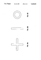
- FIG. 8A illustrates a cross shaped light emitting means
- FIG. 8B illustrates a bar-shaped light emitting means
- FIG. 8B is a ring shaped light emitting means.
- the sight according to FIG. 1 comprises a rectangular and parabolically formed concave-convex lens 10, which is attached in a light channel shaped as a tube 12 having rectangular cross section.
- the lens is attached close to one end of said light channel.
- a transparent body 13 which is directed towards the eye of the gunner.
- the body is rectangular.
- the tube 12 is provided with fastening means 16 for mounting the sight on a gun, preferably on the barrel of the gun.
- the side of the lens directed towards the transparent body 13 is parabolically shaped.
- the lens is mounted in the light channel in such a way that the focal point thereof falls inside of the light channel between the lens 10 and the transparent body 13, below the center line of the light channel.
- the center line of the light channel is defined as the sight line.
- a light emitting means which constitutes the aiming point, formed as a light emitting diode 11.
- the light emitting diode is formed as a ring, while in others the light emitting diode is replaced by an optical fiber, one end thereof opening into the focal point, and the second end thereof being supplied with light, e.g., from a light emitting diode.
- the lens is cut to parabolic shape while in another embodiment it is produced directly in this shape. Three possible configurations of the aiming point are illustrated in FIGS. 8A-8C.
- the parabolic surface of the lens 10 is coated with a partially reflecting layer 10a.
- the layer is reflective to a certain narrow frequency, around the frequency 650 nm, i.e., red light only, while light of other frequencies passes through the lens substantially without reflection.
- the center frequency for reflection is of course chosen in dependence of the frequency of the light emitted from the light emitting means.
- the other side of the lens is cut, or produced, in such a way that it is completely neutral to the light passed through the lens.
- a rechargeable battery switch unit 14 is provided, as is clear from FIG. 2, in a casing 17, projecting from the light channel.
- a switch not shown here is also provided between said battery and the light emitting diode. Because of the rectangular cross section of the light channel, the walls thereof are flat. Exterior on the upper side of the tube a flat solar cell 15 is flush-mounted, said solar cell supplying in this embodiment the battery with charging current. It is also possible that the solar cell directly, or occasionally through a buffer comprising, e.g., a capacitor, is connected to the light emitting diode, the battery in that case being redundant.
- FIG. 6 illustrates the solar cell 15 directly connected to the LED 11.
- the space available for the solar cell is also large.
- a solar cell with a large surface area, having a high output can be used.
- the sight is used preferably outdoors and mostly in daylight.
- the output of the solar cell is switched automatically between the battery and the light emitting diode, depending on the light falling on the solar cell.
- the battery/switch unit 14 of FIG. 7 allows the solar cell to power the LED directly or to charge the battery.
- the sight is arranged without a solar cell.
- the lens can be molded completely in plastics directly to a rectangular shape, fastening and possibly sealing material can be embedded or attached to the lens material for the attachment in the light channel. Also, lenses made of glass can be used.
- a sight substantially made in plastic material is advantageous as to weight and is convenient in many applications.
- the graphic representations of FIG. 3-FIG. 5 show the position of a point along the radius of the lens as a function of angular error or angular deviation existing in different types of sights.
- the angular deviation is defined as the angular deviation for each point of the target projected on the reflecting layer of the lens.
- the graphic representation of FIG. 3 relates to a conventional spherically cut lens, the y-axes specifying the position of the point along a radius of the lens starting from the optical center of the lens.
- the angular deviation is specified on the x-axes and is considered too large to be accepted.
- the graphic representation of FIG. 4 relates to a conventional so called double-cut lens, and as is clear from the graph, considering especially the different scale of the x-axes, the improvement of the lens characteristics is substantial. However, the angular deviation is still too large to be all together sufficient.
- the characteristics of a lens according to the present invention regarding the angular deviation is shown in FIG. 5. Please note the substantially enlarged scale of the x-axes of the graph. In this case the angular deviation can be neglected in all realistic circumstances.
Abstract
Description
Claims (9)
Applications Claiming Priority (2)
| Application Number | Priority Date | Filing Date | Title |
|---|---|---|---|
| SE8901657A SE464104B (en) | 1989-05-10 | 1989-05-10 | PARALLAX-FREE AIM |
| SE8901657 | 1989-05-10 |
Publications (1)
| Publication Number | Publication Date |
|---|---|
| US5189555A true US5189555A (en) | 1993-02-23 |
Family
ID=20375897
Family Applications (1)
| Application Number | Title | Priority Date | Filing Date |
|---|---|---|---|
| US07/521,151 Expired - Fee Related US5189555A (en) | 1989-05-10 | 1990-05-08 | Parallax free optical sighting device |
Country Status (2)
| Country | Link |
|---|---|
| US (1) | US5189555A (en) |
| SE (1) | SE464104B (en) |
Cited By (29)
| Publication number | Priority date | Publication date | Assignee | Title |
|---|---|---|---|---|
| GB2277606A (en) * | 1993-04-29 | 1994-11-02 | Aimpoint Ab | Optical sight having biaspheric element with partially reflecting layer |
| US5452131A (en) * | 1993-03-10 | 1995-09-19 | Sandberg Development Aktiebolag | Sighting device for small arms, comprising a variable aperature |
| US5471777A (en) * | 1993-11-18 | 1995-12-05 | Mcdonald; Kenneth E. | Firearm sighting device |
| GB2317711A (en) * | 1996-09-25 | 1998-04-01 | Firearms Research Ltd | Optical sighting device |
| WO2000044067A1 (en) * | 1999-01-20 | 2000-07-27 | Nokia Networks Oy | Arrangement for aiming a radio link antenna |
| EP1028343A1 (en) * | 1996-02-01 | 2000-08-16 | Firearms Research Limited | Optical sighting devices |
| US6519889B1 (en) * | 2000-07-26 | 2003-02-18 | Hensoldt Systemtechnik Gmbh | Bright point sight |
| US20050241210A1 (en) * | 2004-02-11 | 2005-11-03 | Vitronics Inc. | Dual sight scope system and method |
| US20060162226A1 (en) * | 2005-01-06 | 2006-07-27 | Eotech Acquisition Corp. | Aiming sight having fixed light emitting diode (LED) array and rotatable collimator |
| US20070214701A1 (en) * | 2004-05-06 | 2007-09-20 | Insight Technology, Inc. | Weapon aiming device |
| US7574810B1 (en) * | 2006-07-18 | 2009-08-18 | Truglo, Inc. | Illuminated reflective sighting device |
| WO2009136858A1 (en) | 2008-05-09 | 2009-11-12 | Gs Development Ab | Combination sight |
| US20100079750A1 (en) * | 2008-09-30 | 2010-04-01 | Koehler Albrecht | Coaxially Arranged, Off-Axis Optical System for a Sighting Device or Aiming Device |
| US20100083554A1 (en) * | 2008-10-02 | 2010-04-08 | Trijicon, Inc. | Optical sight |
| US7797843B1 (en) * | 1999-07-15 | 2010-09-21 | Gs Development Ab | Optical sight |
| EP2416201A2 (en) | 2010-08-05 | 2012-02-08 | L-3 Communications Eotech, Inc. | Multipurpose aiming sight with head-up display module |
| CN102456850A (en) * | 2011-09-29 | 2012-05-16 | 昆山维信诺显示技术有限公司 | OLED (Organic Light Emitting Diode) reticle, manufacturing method thereof and reflecting type sighting telescope |
| WO2013032894A1 (en) | 2011-09-02 | 2013-03-07 | Trijicon, Inc. | Reflex sight |
| US20130232845A1 (en) * | 2012-02-20 | 2013-09-12 | Vijay Singh | Battery free light emitting diode reflective dot gunsight |
| CN103681764A (en) * | 2013-11-28 | 2014-03-26 | 北京维信诺科技有限公司 | Organic light-emitting diode reticle (OLED) and manufacturing method thereof and telescopic sight |
| US9982965B2 (en) * | 2014-03-01 | 2018-05-29 | Huanic Corporation | Inner red-dot gun sighting device powered by solar cell and provided with micro-current LED light source |
| JP2018180270A (en) * | 2017-04-13 | 2018-11-15 | 株式会社東京スコープ | Dot sight |
| WO2019030912A1 (en) * | 2017-08-10 | 2019-02-14 | 株式会社東京マルイ | Dot sight |
| SE1850250A1 (en) * | 2018-03-07 | 2019-09-08 | Aimpoint Ab | Reflex sight |
| US10473427B1 (en) | 2017-07-17 | 2019-11-12 | Vista Outdoor Operations Llc | Holster system with removable sight cover |
| US20210247055A1 (en) * | 2018-09-03 | 2021-08-12 | Light Optical Works, Ltd. | Dot sight |
| US11236971B2 (en) * | 2019-07-10 | 2022-02-01 | Primary Arms, Llc | Solar powered cap assembly for optical sighting systems |
| US11287638B2 (en) | 2019-08-20 | 2022-03-29 | Francesco E. DeAngelis | Reflex sight with superluminescent micro-display, dynamic reticle, and metadata overlay |
| US11543209B2 (en) * | 2020-07-22 | 2023-01-03 | Noblex E-Optics Gmbh | Sighting arrangement comprising a prism system with a flat top surface |
Families Citing this family (1)
| Publication number | Priority date | Publication date | Assignee | Title |
|---|---|---|---|---|
| SE513594C2 (en) * | 1999-02-22 | 2000-10-09 | Gs Dev Ab | Device at an optical sight with illuminated benchmark |
Citations (12)
| Publication number | Priority date | Publication date | Assignee | Title |
|---|---|---|---|---|
| US3942901A (en) * | 1973-03-26 | 1976-03-09 | John Arne Ingemund Ekstrand | Optical sighting instrument with means for producing a sighting mark |
| US3963356A (en) * | 1973-12-11 | 1976-06-15 | Aga Aktiebolag | Optical sight |
| US4118126A (en) * | 1977-02-22 | 1978-10-03 | Westinghouse Air Brake Company | Method of locating a light at the focal point of a concave mirror of a signal lamp unit |
| US4346995A (en) * | 1980-07-14 | 1982-08-31 | Morris Donald D | Off axis optical sight system for a firearm |
| US4402605A (en) * | 1979-03-19 | 1983-09-06 | Aimpoint Ab | Firearms sighting instrument |
| US4665622A (en) * | 1985-11-18 | 1987-05-19 | Elbit Computers, Ltd. | Optical sighting device |
| US4743765A (en) * | 1984-09-19 | 1988-05-10 | Interaims Aktiebolag | Arrangement of a sighting mark and a light-producing source of energy therefor |
| US4804858A (en) * | 1987-04-08 | 1989-02-14 | Aimpoint Ab | Power supply circuit for a diode adapted to emit light in dependence of the prevailing surrounding light |
| US4830381A (en) * | 1986-08-15 | 1989-05-16 | Sellner Productions, Inc. | Simulated laser weapon and amusement application therefore |
| US4859058A (en) * | 1987-07-09 | 1989-08-22 | Ekstrand Per Olof S | Improved adjustment means for sighting instrument |
| US4940324A (en) * | 1988-05-25 | 1990-07-10 | American Advantage Company | Electronic sight having a larger horizontal viewing field than a vertical viewing field and method of making same |
| US4945646A (en) * | 1984-11-15 | 1990-08-07 | Interaims Aktiebolag | Arrangement in a luminous dot sighting instrument |
-
1989
- 1989-05-10 SE SE8901657A patent/SE464104B/en not_active IP Right Cessation
-
1990
- 1990-05-08 US US07/521,151 patent/US5189555A/en not_active Expired - Fee Related
Patent Citations (12)
| Publication number | Priority date | Publication date | Assignee | Title |
|---|---|---|---|---|
| US3942901A (en) * | 1973-03-26 | 1976-03-09 | John Arne Ingemund Ekstrand | Optical sighting instrument with means for producing a sighting mark |
| US3963356A (en) * | 1973-12-11 | 1976-06-15 | Aga Aktiebolag | Optical sight |
| US4118126A (en) * | 1977-02-22 | 1978-10-03 | Westinghouse Air Brake Company | Method of locating a light at the focal point of a concave mirror of a signal lamp unit |
| US4402605A (en) * | 1979-03-19 | 1983-09-06 | Aimpoint Ab | Firearms sighting instrument |
| US4346995A (en) * | 1980-07-14 | 1982-08-31 | Morris Donald D | Off axis optical sight system for a firearm |
| US4743765A (en) * | 1984-09-19 | 1988-05-10 | Interaims Aktiebolag | Arrangement of a sighting mark and a light-producing source of energy therefor |
| US4945646A (en) * | 1984-11-15 | 1990-08-07 | Interaims Aktiebolag | Arrangement in a luminous dot sighting instrument |
| US4665622A (en) * | 1985-11-18 | 1987-05-19 | Elbit Computers, Ltd. | Optical sighting device |
| US4830381A (en) * | 1986-08-15 | 1989-05-16 | Sellner Productions, Inc. | Simulated laser weapon and amusement application therefore |
| US4804858A (en) * | 1987-04-08 | 1989-02-14 | Aimpoint Ab | Power supply circuit for a diode adapted to emit light in dependence of the prevailing surrounding light |
| US4859058A (en) * | 1987-07-09 | 1989-08-22 | Ekstrand Per Olof S | Improved adjustment means for sighting instrument |
| US4940324A (en) * | 1988-05-25 | 1990-07-10 | American Advantage Company | Electronic sight having a larger horizontal viewing field than a vertical viewing field and method of making same |
Cited By (63)
| Publication number | Priority date | Publication date | Assignee | Title |
|---|---|---|---|---|
| US5452131A (en) * | 1993-03-10 | 1995-09-19 | Sandberg Development Aktiebolag | Sighting device for small arms, comprising a variable aperature |
| GB2276015B (en) * | 1993-03-10 | 1996-06-05 | Sandberg Dev Ab | A sighting device for small arms |
| US5440387A (en) * | 1993-04-29 | 1995-08-08 | Aimpoint Ab | Optical element of a parallax free sight |
| GB2277606B (en) * | 1993-04-29 | 1996-07-31 | Aimpoint Ab | An assembly of a light emitting means and an optical element of a parallel free sight. |
| GB2277606A (en) * | 1993-04-29 | 1994-11-02 | Aimpoint Ab | Optical sight having biaspheric element with partially reflecting layer |
| US5471777A (en) * | 1993-11-18 | 1995-12-05 | Mcdonald; Kenneth E. | Firearm sighting device |
| EP1028343A1 (en) * | 1996-02-01 | 2000-08-16 | Firearms Research Limited | Optical sighting devices |
| US6327806B1 (en) | 1996-09-25 | 2001-12-11 | Firearms Research Limited | Optical sighting devices |
| GB2317711A (en) * | 1996-09-25 | 1998-04-01 | Firearms Research Ltd | Optical sighting device |
| WO1998013717A2 (en) | 1996-09-25 | 1998-04-02 | Firearms Research Limited | Optical sighting devices |
| WO1998013717A3 (en) * | 1996-09-25 | 1998-05-28 | Clive Rawlinson Paige | Optical sighting devices |
| GB2317711B (en) * | 1996-09-25 | 2001-07-04 | Firearms Res Ltd | Optical sighting devices |
| US6538613B1 (en) | 1999-01-20 | 2003-03-25 | Nokia Corporation | Arrangement for aiming a radio link antenna |
| WO2000044067A1 (en) * | 1999-01-20 | 2000-07-27 | Nokia Networks Oy | Arrangement for aiming a radio link antenna |
| US7797843B1 (en) * | 1999-07-15 | 2010-09-21 | Gs Development Ab | Optical sight |
| US6519889B1 (en) * | 2000-07-26 | 2003-02-18 | Hensoldt Systemtechnik Gmbh | Bright point sight |
| US20050241210A1 (en) * | 2004-02-11 | 2005-11-03 | Vitronics Inc. | Dual sight scope system and method |
| US7640691B2 (en) | 2004-02-11 | 2010-01-05 | Philip B Karcher | Dual sight scope system and method |
| US20070214701A1 (en) * | 2004-05-06 | 2007-09-20 | Insight Technology, Inc. | Weapon aiming device |
| US7325354B2 (en) | 2004-05-06 | 2008-02-05 | Insight Technology, Inc. | Weapon aiming device |
| US20060162226A1 (en) * | 2005-01-06 | 2006-07-27 | Eotech Acquisition Corp. | Aiming sight having fixed light emitting diode (LED) array and rotatable collimator |
| US7225578B2 (en) * | 2005-01-06 | 2007-06-05 | Eotech Acquisition Corp. | Aiming sight having fixed light emitting diode (LED) array and rotatable collimator |
| US7574810B1 (en) * | 2006-07-18 | 2009-08-18 | Truglo, Inc. | Illuminated reflective sighting device |
| WO2009136858A1 (en) | 2008-05-09 | 2009-11-12 | Gs Development Ab | Combination sight |
| US9303952B2 (en) | 2008-05-09 | 2016-04-05 | Gs Development Ab | Combination sight |
| US20110067288A1 (en) * | 2008-05-09 | 2011-03-24 | Hakan Hakansson | Combination sight |
| CN102016487A (en) * | 2008-05-09 | 2011-04-13 | Gs发展公司 | Combination sight |
| DE102008049882A1 (en) | 2008-09-30 | 2010-04-08 | Analytik Jena Ag | Coaxially arranged off-axis optical system for a sighting or aiming device |
| US20100079750A1 (en) * | 2008-09-30 | 2010-04-01 | Koehler Albrecht | Coaxially Arranged, Off-Axis Optical System for a Sighting Device or Aiming Device |
| US7916290B2 (en) | 2008-09-30 | 2011-03-29 | Analytik Jena Ag | Coaxially arranged, off-axis optical system for a sighting device or aiming device |
| US20110203153A1 (en) * | 2008-10-02 | 2011-08-25 | Trijicon, Inc. | Optical sight |
| US8443541B2 (en) | 2008-10-02 | 2013-05-21 | Trijicon, Inc. | Optical sight |
| US8082688B2 (en) * | 2008-10-02 | 2011-12-27 | Trijicon, Inc. | Optical sight |
| US8099897B2 (en) * | 2008-10-02 | 2012-01-24 | Trijicon, Inc. | Optical sight |
| US20100083554A1 (en) * | 2008-10-02 | 2010-04-08 | Trijicon, Inc. | Optical sight |
| US20110219659A1 (en) * | 2008-10-02 | 2011-09-15 | Trijicon, Inc. | Optical sight |
| US8215050B2 (en) * | 2008-10-02 | 2012-07-10 | Trijicon, Inc. | Optical sight |
| EP2416201A2 (en) | 2010-08-05 | 2012-02-08 | L-3 Communications Eotech, Inc. | Multipurpose aiming sight with head-up display module |
| WO2013032894A1 (en) | 2011-09-02 | 2013-03-07 | Trijicon, Inc. | Reflex sight |
| EP2751513A1 (en) * | 2011-09-02 | 2014-07-09 | Trijicon, Inc. | Reflex sight |
| JP2014528051A (en) * | 2011-09-02 | 2014-10-23 | トリジコン インコーポレーテッドTrijicon,Inc. | Reflective sight |
| EP2751513A4 (en) * | 2011-09-02 | 2015-01-21 | Trijicon Inc | Reflex sight |
| US8966805B2 (en) | 2011-09-02 | 2015-03-03 | Trijicon, Inc. | Reflex sight |
| CN102456850A (en) * | 2011-09-29 | 2012-05-16 | 昆山维信诺显示技术有限公司 | OLED (Organic Light Emitting Diode) reticle, manufacturing method thereof and reflecting type sighting telescope |
| CN102456850B (en) * | 2011-09-29 | 2015-11-25 | 昆山维信诺显示技术有限公司 | A kind of OLED graticle and preparation method thereof and reflex sight |
| US20130232845A1 (en) * | 2012-02-20 | 2013-09-12 | Vijay Singh | Battery free light emitting diode reflective dot gunsight |
| CN103681764B (en) * | 2013-11-28 | 2018-04-27 | 固安翌光科技有限公司 | A kind of OLED graticles and preparation method thereof and formula gun sight of looking in the distance |
| CN103681764A (en) * | 2013-11-28 | 2014-03-26 | 北京维信诺科技有限公司 | Organic light-emitting diode reticle (OLED) and manufacturing method thereof and telescopic sight |
| US9982965B2 (en) * | 2014-03-01 | 2018-05-29 | Huanic Corporation | Inner red-dot gun sighting device powered by solar cell and provided with micro-current LED light source |
| JP2018180270A (en) * | 2017-04-13 | 2018-11-15 | 株式会社東京スコープ | Dot sight |
| US10473427B1 (en) | 2017-07-17 | 2019-11-12 | Vista Outdoor Operations Llc | Holster system with removable sight cover |
| US11105583B1 (en) | 2017-07-17 | 2021-08-31 | Vista Outdoor Operations Llc | Holster system with removable sight cover |
| US11555667B2 (en) | 2017-07-17 | 2023-01-17 | Vista Outdoor Operations Llc | Holster system with removable sight cover |
| WO2019030912A1 (en) * | 2017-08-10 | 2019-02-14 | 株式会社東京マルイ | Dot sight |
| JPWO2019030912A1 (en) * | 2017-08-10 | 2020-08-20 | 株式会社東京マルイ | Dot site |
| EP3667392A4 (en) * | 2017-08-10 | 2021-03-17 | TOKYO MARUI Co., Ltd. | Dot sight |
| US11280583B2 (en) | 2018-03-07 | 2022-03-22 | Aimpoint Ab | Reflex sight |
| SE1850250A1 (en) * | 2018-03-07 | 2019-09-08 | Aimpoint Ab | Reflex sight |
| US20210247055A1 (en) * | 2018-09-03 | 2021-08-12 | Light Optical Works, Ltd. | Dot sight |
| US11604344B2 (en) * | 2018-09-03 | 2023-03-14 | Light Optical Works, Ltd. | Dot sight |
| US11236971B2 (en) * | 2019-07-10 | 2022-02-01 | Primary Arms, Llc | Solar powered cap assembly for optical sighting systems |
| US11287638B2 (en) | 2019-08-20 | 2022-03-29 | Francesco E. DeAngelis | Reflex sight with superluminescent micro-display, dynamic reticle, and metadata overlay |
| US11543209B2 (en) * | 2020-07-22 | 2023-01-03 | Noblex E-Optics Gmbh | Sighting arrangement comprising a prism system with a flat top surface |
Also Published As
| Publication number | Publication date |
|---|---|
| SE464104B (en) | 1991-03-04 |
| SE8901657D0 (en) | 1989-05-10 |
| SE8901657L (en) | 1990-11-11 |
Similar Documents
| Publication | Publication Date | Title |
|---|---|---|
| US5189555A (en) | Parallax free optical sighting device | |
| KR900000059B1 (en) | Arrangement of a sighting mark and a light-producting source of energy therefor | |
| US5052801A (en) | Compact laser-assisted weapon sight | |
| US5359779A (en) | Illumination and laser sighting device for a weapon | |
| US7472830B2 (en) | Compact laser aiming assembly for a firearm | |
| US4313272A (en) | Laser beam firearm aim assisting methods and apparatus | |
| US7574810B1 (en) | Illuminated reflective sighting device | |
| US5493450A (en) | Sighting instrument | |
| US5373644A (en) | Reflex luminous dot sighting instrument with undesired dot light blocking | |
| US7325318B2 (en) | Compact multifunction sight | |
| US5054917A (en) | Automatic boresighting device for an optronic system | |
| US7997022B2 (en) | Method and apparatus for collimating and coaligning optical components | |
| US5040885A (en) | Telescope designator | |
| JPH10503833A (en) | Laser alignment system for small arms | |
| US4963096A (en) | Device and method for improving shooting skills | |
| KR200398487Y1 (en) | a Day-and-Night scope | |
| JPH0756088A (en) | Optical device of gunsight without parallax | |
| EP0069575A2 (en) | Improved collimator gun sight | |
| US4126394A (en) | Optical cant sensor for mortars | |
| US2925657A (en) | Sighting devices | |
| US3481658A (en) | Sighting telescopes having a luminous aiming mark | |
| KR820000561Y1 (en) | Night sight device | |
| GB1579796A (en) | Collimator gun sight | |
| US5020906A (en) | Boresight module | |
| EP1350072B1 (en) | Optical sight |
Legal Events
| Date | Code | Title | Description |
|---|---|---|---|
| AS | Assignment |
Owner name: AIMPOINT AB, JAGERSHILLGATAN 15, S-213 75 MALMO, S Free format text: ASSIGNMENT OF ASSIGNORS INTEREST.;ASSIGNOR:JORLOV, RICKARD;REEL/FRAME:005393/0497 Effective date: 19900608 |
|
| CC | Certificate of correction | ||
| FEPP | Fee payment procedure |
Free format text: PAYOR NUMBER ASSIGNED (ORIGINAL EVENT CODE: ASPN); ENTITY STATUS OF PATENT OWNER: LARGE ENTITY |
|
| FPAY | Fee payment |
Year of fee payment: 4 |
|
| FEPP | Fee payment procedure |
Free format text: PAYOR NUMBER ASSIGNED (ORIGINAL EVENT CODE: ASPN); ENTITY STATUS OF PATENT OWNER: LARGE ENTITY |
|
| FPAY | Fee payment |
Year of fee payment: 8 |
|
| REMI | Maintenance fee reminder mailed | ||
| LAPS | Lapse for failure to pay maintenance fees | ||
| STCH | Information on status: patent discontinuation |
Free format text: PATENT EXPIRED DUE TO NONPAYMENT OF MAINTENANCE FEES UNDER 37 CFR 1.362 |
|
| FP | Lapsed due to failure to pay maintenance fee |
Effective date: 20050223 |