US5188883A - Composite tape structures - Google Patents
Composite tape structures Download PDFInfo
- Publication number
- US5188883A US5188883A US07/709,469 US70946991A US5188883A US 5188883 A US5188883 A US 5188883A US 70946991 A US70946991 A US 70946991A US 5188883 A US5188883 A US 5188883A
- Authority
- US
- United States
- Prior art keywords
- layer
- tape
- water blocking
- metal tape
- tape layer
- Prior art date
- Legal status (The legal status is an assumption and is not a legal conclusion. Google has not performed a legal analysis and makes no representation as to the accuracy of the status listed.)
- Expired - Lifetime
Links
Images


Classifications
-
- G—PHYSICS
- G02—OPTICS
- G02B—OPTICAL ELEMENTS, SYSTEMS OR APPARATUS
- G02B6/00—Light guides; Structural details of arrangements comprising light guides and other optical elements, e.g. couplings
- G02B6/44—Mechanical structures for providing tensile strength and external protection for fibres, e.g. optical transmission cables
- G02B6/4479—Manufacturing methods of optical cables
- G02B6/4486—Protective covering
-
- B—PERFORMING OPERATIONS; TRANSPORTING
- B29—WORKING OF PLASTICS; WORKING OF SUBSTANCES IN A PLASTIC STATE IN GENERAL
- B29C—SHAPING OR JOINING OF PLASTICS; SHAPING OF MATERIAL IN A PLASTIC STATE, NOT OTHERWISE PROVIDED FOR; AFTER-TREATMENT OF THE SHAPED PRODUCTS, e.g. REPAIRING
- B29C48/00—Extrusion moulding, i.e. expressing the moulding material through a die or nozzle which imparts the desired form; Apparatus therefor
- B29C48/03—Extrusion moulding, i.e. expressing the moulding material through a die or nozzle which imparts the desired form; Apparatus therefor characterised by the shape of the extruded material at extrusion
- B29C48/07—Flat, e.g. panels
- B29C48/08—Flat, e.g. panels flexible, e.g. films
-
- G—PHYSICS
- G02—OPTICS
- G02B—OPTICAL ELEMENTS, SYSTEMS OR APPARATUS
- G02B6/00—Light guides; Structural details of arrangements comprising light guides and other optical elements, e.g. couplings
- G02B6/44—Mechanical structures for providing tensile strength and external protection for fibres, e.g. optical transmission cables
- G02B6/4401—Optical cables
- G02B6/4407—Optical cables with internal fluted support member
-
- G—PHYSICS
- G02—OPTICS
- G02B—OPTICAL ELEMENTS, SYSTEMS OR APPARATUS
- G02B6/00—Light guides; Structural details of arrangements comprising light guides and other optical elements, e.g. couplings
- G02B6/44—Mechanical structures for providing tensile strength and external protection for fibres, e.g. optical transmission cables
- G02B6/4401—Optical cables
- G02B6/4429—Means specially adapted for strengthening or protecting the cables
- G02B6/44384—Means specially adapted for strengthening or protecting the cables the means comprising water blocking or hydrophobic materials
-
- B—PERFORMING OPERATIONS; TRANSPORTING
- B29—WORKING OF PLASTICS; WORKING OF SUBSTANCES IN A PLASTIC STATE IN GENERAL
- B29C—SHAPING OR JOINING OF PLASTICS; SHAPING OF MATERIAL IN A PLASTIC STATE, NOT OTHERWISE PROVIDED FOR; AFTER-TREATMENT OF THE SHAPED PRODUCTS, e.g. REPAIRING
- B29C48/00—Extrusion moulding, i.e. expressing the moulding material through a die or nozzle which imparts the desired form; Apparatus therefor
-
- Y—GENERAL TAGGING OF NEW TECHNOLOGICAL DEVELOPMENTS; GENERAL TAGGING OF CROSS-SECTIONAL TECHNOLOGIES SPANNING OVER SEVERAL SECTIONS OF THE IPC; TECHNICAL SUBJECTS COVERED BY FORMER USPC CROSS-REFERENCE ART COLLECTIONS [XRACs] AND DIGESTS
- Y10—TECHNICAL SUBJECTS COVERED BY FORMER USPC
- Y10S—TECHNICAL SUBJECTS COVERED BY FORMER USPC CROSS-REFERENCE ART COLLECTIONS [XRACs] AND DIGESTS
- Y10S428/00—Stock material or miscellaneous articles
- Y10S428/913—Material designed to be responsive to temperature, light, moisture
-
- Y—GENERAL TAGGING OF NEW TECHNOLOGICAL DEVELOPMENTS; GENERAL TAGGING OF CROSS-SECTIONAL TECHNOLOGIES SPANNING OVER SEVERAL SECTIONS OF THE IPC; TECHNICAL SUBJECTS COVERED BY FORMER USPC CROSS-REFERENCE ART COLLECTIONS [XRACs] AND DIGESTS
- Y10—TECHNICAL SUBJECTS COVERED BY FORMER USPC
- Y10T—TECHNICAL SUBJECTS COVERED BY FORMER US CLASSIFICATION
- Y10T428/00—Stock material or miscellaneous articles
- Y10T428/24—Structurally defined web or sheet [e.g., overall dimension, etc.]
- Y10T428/24752—Laterally noncoextensive components
-
- Y—GENERAL TAGGING OF NEW TECHNOLOGICAL DEVELOPMENTS; GENERAL TAGGING OF CROSS-SECTIONAL TECHNOLOGIES SPANNING OVER SEVERAL SECTIONS OF THE IPC; TECHNICAL SUBJECTS COVERED BY FORMER USPC CROSS-REFERENCE ART COLLECTIONS [XRACs] AND DIGESTS
- Y10—TECHNICAL SUBJECTS COVERED BY FORMER USPC
- Y10T—TECHNICAL SUBJECTS COVERED BY FORMER US CLASSIFICATION
- Y10T428/00—Stock material or miscellaneous articles
- Y10T428/24—Structurally defined web or sheet [e.g., overall dimension, etc.]
- Y10T428/24777—Edge feature
- Y10T428/24793—Comprising discontinuous or differential impregnation or bond
-
- Y—GENERAL TAGGING OF NEW TECHNOLOGICAL DEVELOPMENTS; GENERAL TAGGING OF CROSS-SECTIONAL TECHNOLOGIES SPANNING OVER SEVERAL SECTIONS OF THE IPC; TECHNICAL SUBJECTS COVERED BY FORMER USPC CROSS-REFERENCE ART COLLECTIONS [XRACs] AND DIGESTS
- Y10—TECHNICAL SUBJECTS COVERED BY FORMER USPC
- Y10T—TECHNICAL SUBJECTS COVERED BY FORMER US CLASSIFICATION
- Y10T428/00—Stock material or miscellaneous articles
- Y10T428/24—Structurally defined web or sheet [e.g., overall dimension, etc.]
- Y10T428/24802—Discontinuous or differential coating, impregnation or bond [e.g., artwork, printing, retouched photograph, etc.]
- Y10T428/24843—Discontinuous or differential coating, impregnation or bond [e.g., artwork, printing, retouched photograph, etc.] with heat sealable or heat releasable adhesive layer
-
- Y—GENERAL TAGGING OF NEW TECHNOLOGICAL DEVELOPMENTS; GENERAL TAGGING OF CROSS-SECTIONAL TECHNOLOGIES SPANNING OVER SEVERAL SECTIONS OF THE IPC; TECHNICAL SUBJECTS COVERED BY FORMER USPC CROSS-REFERENCE ART COLLECTIONS [XRACs] AND DIGESTS
- Y10—TECHNICAL SUBJECTS COVERED BY FORMER USPC
- Y10T—TECHNICAL SUBJECTS COVERED BY FORMER US CLASSIFICATION
- Y10T428/00—Stock material or miscellaneous articles
- Y10T428/28—Web or sheet containing structurally defined element or component and having an adhesive outermost layer
- Y10T428/2804—Next to metal
-
- Y—GENERAL TAGGING OF NEW TECHNOLOGICAL DEVELOPMENTS; GENERAL TAGGING OF CROSS-SECTIONAL TECHNOLOGIES SPANNING OVER SEVERAL SECTIONS OF THE IPC; TECHNICAL SUBJECTS COVERED BY FORMER USPC CROSS-REFERENCE ART COLLECTIONS [XRACs] AND DIGESTS
- Y10—TECHNICAL SUBJECTS COVERED BY FORMER USPC
- Y10T—TECHNICAL SUBJECTS COVERED BY FORMER US CLASSIFICATION
- Y10T428/00—Stock material or miscellaneous articles
- Y10T428/28—Web or sheet containing structurally defined element or component and having an adhesive outermost layer
- Y10T428/2813—Heat or solvent activated or sealable
- Y10T428/2817—Heat sealable
- Y10T428/2826—Synthetic resin or polymer
Definitions
- a core of the cable is normally surrounded by a metal field which is, in turn, covered by an extruded polymeric jacket.
- a tape layer of swellable water blocking material between the metal shield and the core, this tape layer being provided by a tape of the swellable material which is wrapped around the core in an in-line operation and before the shield is added.
- a binder tape needs to be wrapped around the tape layer of water blocking material immediately after it has been applied around the core so as to hold it in position before the wrapping of the shield around the water blocking material.
- the use of a tape layer of swellable water blocking material has necessarily included extra processing steps and apparatus for the application of the binder together with attendant additional costs.
- the percentage "downtime" in use of the manufacturing process is potentially increased because of probable breakage of the binder tape. Binder tape breakage also tends to increase the amount of cable wastage.
- the present invention provides a tape in the use of which, for the manufacture of cable, a composite binder tape structure may be avoided while producing water blocking material underneath the shield.
- the invention also provides a method of making the inventive composite tape structure method.
- a composite tape structure comprising a metal tape layer and a layer of swellable water blocking material, the two layers bonded together with the layer of swellable water blocking material extending along one side surface of the metal tape layer.
- the composite tape structure of the invention as defined above may be applied to a cable core to provide the swellable water blocking material and the shield and is applied in a single operation with the swellable material supported by the metal layer, before, during and after application.
- the swellable water blocking material and the shield are applied simultaneously around the cable and a binder tape is thus not required for holding the swellable material in position. Any disadvantages which would be inherent in the use of a binding tape are thereby avoided.
- the swellable material is preferably provided as a tape layer and the metal tape layer and water blocking tape are bonded together.
- An adhesive may be provided upon the one side surface of the metal tape layer.
- the metal tape layer has a thermoplastic coating on the one side surface, the thermoplastic coating being softened to provide an adhesive.
- the metal tape layer is provided on one side surface with a thermoplastic coating extending continuously along one longitudinally extending edge region of the metal tape layer and on the other side surface with a thermoplastic coating extending continuously along the other edge region, and the one edge region of the metal layer extends laterally beyond the tape layer of swellable water blocking material so that the thermoplastic coating is unobscured on said one longitudinally extending edge region.
- the composite tape structure is wrapped around the core of a cable to provide a composite shield and a water blocking structure and with the shield layer on the outside of the water blocking layer, the two edge regions of the metal tape layer may be caused to overlap and the thermoplastic coatings to fuse together by the application of heat such as when extruding jacket material onto the shield.
- the composite tape structure according to the invention has laterally extending corrugations lying side-by-side longitudinally of the tape.
- a method of making a composite tape structure comprising providing a metal tape layer and a swellable water blocking material and causing a bond between the metal tape layer and the water blocking material with the water blocking material extending along and providing another layer on said one side surface of the metal tape layer.
- the layer of water blocking material may be provided by a tape layer which is laid against and bonded to the metal tape layer or by a powdered form of the swellable water blocking material which is applied along the one surface of the metal tape layer.
- FIG. 1 is an isometric view of part of a sectioned prior art cable
- FIG. 2 is a diagrammatic side elevational view of apparatus used in the manufacture of the prior art cable of FIG. 1;
- FIG. 3 is an isometric view of part of a sectioned cable using a composite tape structure according to a first embodiment as a composite shield and water blocking tape structure;
- FIG. 4 is a cross-sectional view through the cable of FIG. 3 taken along line IV--IV in FIG. 3;
- FIG. 5 is a diagrammatic side elevational view of apparatus for forming the composite tape structure of the first embodiment and applying it to a cable core during manufacture of the cable of the first embodiment;
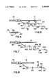
- FIG. 6 is a cross-sectional view taken along line VI--VI in FIG. 5 of the composite tape structure of the first embodiment.
- FIGS. 7 and 8 are diagrammatic side elevational views of apparatus for forming composite tape structures according to second and third embodiment and applying them to cable; cores during the manufacture of cables;
- FIG. 9 is another cross-sectional view through a cable using a composite tape structure of a fourth embodiment.
- FIGS. 10, 11 and 12 are diagrammatic side elevational views of apparatus for the manufacture of composite tape structures according to fifth, sixth and seventh embodiments.
- FIG. 13 is a diagrammatic side elevational view of apparatus for applying a composite tape structure to a cable core, the tape having been made upon the apparatus shown in any of FIGS. 10, 11 and 12.
- a cable core is normally surrounded by a metal shield and this, in turn, is surrounded by a polymeric jacket.
- the water blocking material is applied as a tape layer which is wrapped around the cable core before a metal tape layer is wrapped around the core for forming the metal shield. Because the swellable water blocking tape layer is extremely flimsy and non-rigid in nature, it is essential to wrap at least one binding tape helically around the layer of swellable water blocking material to hold it in its desired position around the core before application of the metal tape layer.
- FIG. 1 represents an optical cable 10.
- the optical cable 10 has a core 12 composed of an elongate plastic extruded core member 14, a longitudinally extending tensile reinforcing means which may be a central strength member 16, and transmission elements housed in helically extending grooves 19 formed around the outside of the core member 14.
- These transmission elements are either groups of optical fibers directly inserted into the grooves or alternatively, comprise flexible plastics tubes 18, as shown held within the grooves, the plastics tubes containing groups of optical fibers.
- a water blocking material which may comprise a grease or jelly water blocking substance, or a swellable water blocking powder surrounds the transmission elements within the grooves.
- a tape layer of swellable water blocking material 20 Surrounding the core 12 in this prior construction is a tape layer of swellable water blocking material 20 having longitudinally extending edges which abut or overlap one over the other.
- This tape layer is surrounded by one or possibly two helically extending binding tapes 22 and around the tape layer 20 is a corrugated metal shield 24.
- a corrugated metal shield 24 Immediately surrounding the metal shield is an extruded polymeric jacket 26.
- the cable 10 is manufactured partly by the use of the apparatus shown in FIG. 2.
- the core 12 is moved along a passline, through tape forming apparatus 28 at which the layer 20 of swellable water blocking tape is applied around the core, axially through two binding heads 30, to apply the binding tapes 22, and then through a further tape forming apparatus 32 at which the shield 24 is provided.
- the shield is provided by a flat metal tape 34 issuing from a reel 36, the tape 34 passing across a welder 37 for welding together tapes from successive reels.
- the tape 34 passes through corrugating rolls 38 to be formed with laterally extending and longitudinally spaced corrugations as shown at 39 in FIG. 2.
- binding heads 30 and the reeled binding tape add to the cost of manufacture of the cable. Further to this, binding tapes are known to break, sometimes frequently during operation. Such breakage adds to the cost of manufacture of a cable and also adds to the time required for its manufacture. Binding tape usage is therefore highly inconvenient and is expensive.
- an optical cable 40 comprises a core 41 and a jacket 43 similar in construction to those described in the first embodiment.
- Flexible plastic tubes 45 are disposed within and extend along grooves 47 of the core, the tubes each housing a group of optical fibers 49 (FIG. 4).
- the space in each groove surrounding its tube 45 is occupied by a conventional water blocking grease or jelly 51 or a swellable water blocking powder such as described in U.S. Pat. No. 4,401,366 granted to T. Hope.
- a composite shield and water blocking tape structure 42 formed from a composite tape structure 42a (FIG. 6) forming a first embodiment of the invention.
- the tape structure 42 is comprised of two layers, i.e.
- longitudinally extending edge regions 48 and 50 of the shield layer 44 overlap.
- the shield layer is coated completely over both sides with a plastic coating which is an ethylene copolymer.
- the confronting layers of ethylene copolymer at the overlapped edges 48 and 50 are fused together to provide a seal between the overlapped edges, the fusing together of the plastic layers being caused by a softening of the ethylene copolymer by heat provided during extrusion of the jacket 43 onto the shield.
- the layer 46 of the water blocking material does not extend between the overlapped edges, but the edges 52 of the water blocking material substantially butt together.
- no binding tape extends around the layer 46 of water blocking material.
- the composite tape structure 42a of the first embodiment is manufactured and applied to the core 41 of the cable 40 to form the composite shield and water blocking structure 42 in the following manner.
- the core 41 is fed through a shield forming apparatus 54 of conventional structure.
- a metal tape 44a for forming the shield layer 44 is drawn from a reel 56 and is passed downstream past a welder 58 and a heater 60 towards the shield forming apparatus 54.
- a tape 46a of the swellable water blocking material is unreeled from a reel 62 and is fed in the same direction.
- the swellable water blocking tape 46a is provided by a particulate swellable material, such as sodium polyacrylate, which is held upon a tape substrate or between substrates.
- the substrates are preferably non-woven and may be in the form of paper.
- the heater softens the ethylene copolymer covering one side of the tape and the tape 44a bearing the softened ethylene copolymer passes between pinch rolls 64 together with the tape 46a from reel 62.
- the softened copolymer sticks to the tape 46a so that, after hardening of the copolymer, the two tapes 44a and 46a are bonded together.
- the composite tape structure 42a having two layers formed of the bonded tapes 44a and 46a then passes between corrugating rolls 66 where the metal tape layer 44a is formed with longitudinally extending corrugations 68 as shown in FIG. 5, the tape 46a being forced to conform to the corrugated shape of the metal.
- the corrugating process positively increases the degree of bonding between the two layers.
- the tapes 44a and 46a are of such relative widths and are relatively disposed so that when combined together to form the composite tape structure 42a as shown in FIG. 6, the water blocking tape 46a extends only partly across the one side surface of the metal tape 44a so that this one side surface is not obscured by the tape 46a at the longitudinally extending edge region 48 of the metal tape.
- the longitudinally extending edge regions 48 and 50 overlap so that the ethylene copolymer coatings directly confront one another to enable the fusing process to take place between them.
- the width of the water blocking material tape layer 46 is such that the edges 52 substantially abut when assembled onto the core as described above and with reference to FIG. 4.
- binding heads, binding reels and binding tapes are completely unnecessary thereby avoiding disadvantages normally associated with use of binding tapes.
- the swellable water blocking layer 46 is successful in preventing moisture from passing along the inside surface of the metal shield layer 44. Contact of any portion of the layer 46 by moisture results in a swelling of the sodium polyacrylate material to provide its water blocking function by blocking all gaps between the shield layer and the core 41 and the water blocking substance 51 in the grooves.
- FIG. 7 shows an apparatus for the manufacture of a composite tape structure 42a of a second embodiment and for applying it to optical cable core.
- This structure 42a is of the same structure as that of the first embodiment with reference to FIG. 6 except that the ethylene copolymer does not adhere the tapes 44a and 46a together.
- the ethylene copolymer extends only along the surfaces of the tape 44a which provides the overlapping edge regions 48 and 50 of the shield layer 46 at which fusing is to occur between the coatings of the ethylene copolymer.
- the tape 46a is passed over an adhesive applicator 70.
- a heater 60 such as described with reference to FIG. 5 is not included.
- an adhesive is controllably coated onto the one surface of the tape 46 a to provide adherence to the tape 44a.
- the adhesive may be any suitable adhesive for this purpose and needs to be compatible with the materials of the two layers.
- One suitable adhesive is that supplied by Minnesota Manufacturing & Machinery Limited under the trade name "Super 77". This adhesive is used is a vapor barrier adhesive in buildings for causing adherence between plastic vapor barrier sheets and wooden studs.
- the apparatus shown in FIG. 8 is used in the manufacture of a composite tape structure of a third embodiment and for applying it to a cable.
- the structure of the third embodiment is substantially of the structure described with reference to the first embodiment except that the tape layer 46 of water blocking material is replaced by a layer of particulate sodium polyacrylate.
- the metal tape layer 44a passes from its reel 56 beneath a heater 60 as described in the first embodiment to soften the thermoplastic coating and then beneath a hopper 62 which supplies the particulate sodium polyacrylate material onto the softened copolymer as the tape passes beneath.
- the tape 44a bearing the particulate sodium polyacrylate then proceeds between the consolidating rolls 64 and the corrugating rolls 66 before proceeding to the shield forming apparatus 54.
- the swellable water blocking material extends only partly across the metal tape 44a so that a longitudinally extending edge region of the metal tape is completely unobscured as shown in FIG. 6.
- a composite tape structure which is basically of the structure shown in the first embodiment with reference to FIGS. 3 and 4 does not have the unobscured edge region.
- a composite shield and water blocking tape structure 78 lying between a core 79 and a polymeric jacket 81 has a corrugated metal shield layer 80 and a layer 82 of swellable water blocking material lying radially within the metal shield layer with the two layers bonded together.
- the two layers 80 and 82 are laterally coextensive so that the water blocking layer 82 extends between the overlapped longitudinally extending edge regions 84 and 86 of the metal shield layer.
- the edge regions 84 and 86 are not fused together as in the preceding embodiments.
- the interpositioning of the water blocking layer 82 between the edge regions 84 and 86 prevents the ingress of moisture between these edge regions and towards the cable core in that any moisture present beneath the jacket, upon contacting the edge of the layer 82 causes a swelling of layer 82 within the overlap to provide water blockage.
- the composite tape structure 78 of the cable may be constructed upon any of the apparatus described with regard to the first, second or third embodiments.
- composite shield and water blocking tape structure is of uncorrugated form so that the corrugating rolls 66 described in the apparatus are unnecessary.
- the metal of the composite tape structure itself may be of any suitable material such as carbon steel or aluminum.
- the composite tape structures provide tapes swellable water blocking in which overlap is avoided therefore reducing the cost of such an overlap.
- the shield layer may be positioned more closely around the core than would be possible if the swellable water blocking material were applied to the core before application of the shield layer.
- cable diameters may be advantageously minimized.
- these tape layers may have minimal strength in their supporting substrates merely relating to the unreeling process thereby minimizing the cost of such tapes.
- Composite tape structures according to the invention and for providing the metal shield layer and the layer of swellable water blocking material may be preformed and is unreeled as a preformed composite tape structure for wrapping around the cable core.
- manufacture of preformed tape structures are described.
- a preformed composite tape structure 90 is composed of a metal tape layer 92 and a tape layer 94 of the swellable water blocking material. These tape layers are fed respectively from reels 96 and 98 between consolidating rolls 100 at which they converge to form the tape 90.
- the tape 90 is reeled onto a reel 102 for storage purposes and before being placed in an in-line apparatus for the manufacture of an optical cable.
- the tape layer 92 has a coating of ethylene acrylic copolymer, on both of its surfaces as described in the first embodiment, and is fed beneath a heater 104 for softening the coating on one side of the layer 92 in a similar fashion to that described with reference to FIG. 5.
- the two tapes when passing between the consolidating rolls 100 bond together and the ethylene acrylic coating hardens to form a bond.
- the tape layer 94 is fed over an adhesive applicator 106 to apply adhesive to one side surface of the tape layer before passing the tape layers 92 and 94 between the consolidating rolls.
- the tape layer 92 need not have the ethylene acrylic copolymer covering the whole of each of its two sides.
- a composite tape 108 is formed from a metal tape layer 110 having a layer of sodium polyacrylate particulate material bonded to one of its surfaces.
- the metal tape layer 110 is provided with an adhesive from an adhesive applicator 112 before passing beneath a powder applicator 114 and then proceeding through consolidating rolls 116 to bond the particles to the one surface of the metal tape layer.
- the adhesive applicator 112 is replaced by a heater (not shown) for softening an ethylene acrylic layer on one side of the metal tape layer 110 so that the particles of sodium polyacrylate adhere to the softened layer.
- the swellable water blocking material may extend completely across the width of the metal tape layer or alternatively the metal tape layer may extend laterally beyond the water blocking material to provide an unobscured longitudinally extending edge region as shown in FIG. 6 for instance.
- an optical cable of the construction shown in any of the first to the fourth embodiments is provided upon apparatus having preformed tape structures 90 or 108 as described with reference to the fifth to seventh embodiments (FIGS. 10 to 12).
- the tape structure 90 or 108 on the spool 102 is fed directly through corrugating rollers 66 and then through the shield forming apparatus 54, as described with regard to FIG. 5, before being wrapped around the core 12 for the cable.
Abstract
Description
Claims (7)
Priority Applications (1)
| Application Number | Priority Date | Filing Date | Title |
|---|---|---|---|
| US07/709,469 US5188883A (en) | 1990-03-22 | 1991-06-03 | Composite tape structures |
Applications Claiming Priority (2)
| Application Number | Priority Date | Filing Date | Title |
|---|---|---|---|
| US07/498,257 US5039197A (en) | 1990-03-22 | 1990-03-22 | Cable and tape structures therefor |
| US07/709,469 US5188883A (en) | 1990-03-22 | 1991-06-03 | Composite tape structures |
Related Parent Applications (1)
| Application Number | Title | Priority Date | Filing Date |
|---|---|---|---|
| US07/498,257 Division US5039197A (en) | 1990-03-22 | 1990-03-22 | Cable and tape structures therefor |
Publications (1)
| Publication Number | Publication Date |
|---|---|
| US5188883A true US5188883A (en) | 1993-02-23 |
Family
ID=27052770
Family Applications (1)
| Application Number | Title | Priority Date | Filing Date |
|---|---|---|---|
| US07/709,469 Expired - Lifetime US5188883A (en) | 1990-03-22 | 1991-06-03 | Composite tape structures |
Country Status (1)
| Country | Link |
|---|---|
| US (1) | US5188883A (en) |
Cited By (33)
| Publication number | Priority date | Publication date | Assignee | Title |
|---|---|---|---|---|
| US5302428A (en) * | 1992-09-29 | 1994-04-12 | Shaw Industries Ltd. | Multi-layer wraparound heat shrink sleeve |
| WO1997008579A1 (en) * | 1995-08-24 | 1997-03-06 | Owens Corning | Water blocking optical cable reinforcement |
| US5777260A (en) * | 1995-03-14 | 1998-07-07 | Siemens Aktiengesellschaft | Coaxial cable additionally having at least one light waveguide |
| US5930431A (en) * | 1997-12-31 | 1999-07-27 | Siecor Operations, Llc | Fiber optic cable |
| USRE36307E (en) * | 1992-08-25 | 1999-09-21 | Pirelli Cable Corporation | Multi-layer power cable with metal sheath free to move relative to adjacent layers |
| US6003565A (en) * | 1998-02-26 | 1999-12-21 | Bgf Industries, Inc. | Woven fiberglass cable wrap |
| US6066798A (en) * | 1995-06-07 | 2000-05-23 | Siecor Corporation | Slotted core telecommunications cable |
| US6103317A (en) * | 1995-05-23 | 2000-08-15 | Glastic Corporation | Water swellable compositions |
| US6167180A (en) * | 1997-09-12 | 2000-12-26 | Alcatel | Cable having at least one layer of flexible strength members with adhesive and non-adhesive yarns for coupling an outer protective jacket and a buffer tube containing optical fibers |
| US6169834B1 (en) | 1998-05-13 | 2001-01-02 | Alcatel | Slotted composite cable having a cable housing with a tubular opening for copper pairs and a slot for an optical fiber |
| US6178278B1 (en) | 1997-11-13 | 2001-01-23 | Alcatel | Indoor/outdoor dry optical fiber cable |
| US6195486B1 (en) | 1998-06-02 | 2001-02-27 | Siecor Operations, Llc | Fiber optic cable having a component with an absorptive polymer coating and a method of making the cable |
| US6253012B1 (en) | 1998-11-12 | 2001-06-26 | Alcatel | Cycled fiber lock for cross-functional totally dry optical fiber loose tube cable |
| US6284367B1 (en) | 1996-11-14 | 2001-09-04 | Neptco, Inc. | Process for the preparation of nonwoven water blocking tapes and their use in cable manufacture |
| EP1170614A1 (en) * | 2000-06-07 | 2002-01-09 | Lucent Technologies Inc. | Dry-blocked armored cable having reduced water penetration |
| US6348236B1 (en) | 1996-08-23 | 2002-02-19 | Neptco, Inc. | Process for the preparation of water blocking tapes and their use in cable manufacture |
| US20020039869A1 (en) * | 2000-07-24 | 2002-04-04 | Felix Achille | Thermoplastic superabsorbent polymer blend compositions and their preparation |
| US6466720B1 (en) * | 1998-11-30 | 2002-10-15 | Pirelli General Plc | Optical fibre cable manufacture |
| US6542674B1 (en) | 2000-08-25 | 2003-04-01 | Corning Cable Systems Llc | Fiber optic cables with strength members |
| US20030103741A1 (en) * | 2001-11-30 | 2003-06-05 | Dieter Heinl | Optical fiber cable |
| US20030118295A1 (en) * | 2001-12-26 | 2003-06-26 | Lail Jason C. | Fiber optic cable having a ripcord |
| US6677394B1 (en) | 1996-12-18 | 2004-01-13 | Henkel Kommanditgesellschaft Auf Aktien | Swellable hotmelt adhesive |
| US6803400B1 (en) | 1998-12-23 | 2004-10-12 | Henkel Kommanditgesellschaft Auf Aktien | Water-swellable hot-melt-type adhesive |
| US20040229536A1 (en) * | 2003-05-16 | 2004-11-18 | Bahlmann Craig A. | Water blocking cable tape and methods for making same |
| WO2006061555A1 (en) * | 2004-12-07 | 2006-06-15 | Emtelle (Uk) Limited | Tube assembly accomodating optical fibres and method of manufacturing same |
| US7539380B1 (en) | 2007-11-26 | 2009-05-26 | Corning Cable Systems Llc | Fiber optic cables and assemblies for fiber toward the subscriber applications |
| US20090136184A1 (en) * | 2007-11-26 | 2009-05-28 | Abernathy George C | Fiber Optic Cables and Assemblies for Fiber Toward the Subscriber Applications |
| US20090280301A1 (en) * | 2008-05-06 | 2009-11-12 | Intertape Polymer Corp. | Edge coatings for tapes |
| US20100112294A1 (en) * | 2008-11-04 | 2010-05-06 | Shurtape Technologies, Inc. | Corrugated metallic foil tape |
| US20110229098A1 (en) * | 2008-09-23 | 2011-09-22 | Abernathy George C | Fiber optic cables and assemblies for fiber toward the subscriber applications |
| US9308703B2 (en) | 2008-11-04 | 2016-04-12 | Shurtape Technologies, Llc | Device for making corrugated metallic foil tape |
| US9715073B1 (en) * | 2015-02-19 | 2017-07-25 | Afl Telecommunications Llc | Optical trunk cable having web-connected sub-unitized configuration |
| JP2020091452A (en) * | 2018-12-07 | 2020-06-11 | 株式会社フジクラ | Optical fiber cable |
Citations (21)
| Publication number | Priority date | Publication date | Assignee | Title |
|---|---|---|---|---|
| US2224189A (en) * | 1939-06-12 | 1940-12-10 | Signode Steel Strapping Co | Metallic package-binder strap |
| US3574109A (en) * | 1967-05-09 | 1971-04-06 | Yutaka Yoshikawa | Heat insulating laminate |
| US3770556A (en) * | 1970-08-07 | 1973-11-06 | Reychem Corp | Wraparound closure sleeve |
| US4323721A (en) * | 1980-02-08 | 1982-04-06 | Belden Corporation | Electric cables with improved shielding member |
| US4324827A (en) * | 1979-01-17 | 1982-04-13 | Hiraoka & Co., Ltd. | Water-proof, fuse-bonding fabric |
| US4327246A (en) * | 1980-02-19 | 1982-04-27 | Belden Corporation | Electric cables with improved shielding members |
| US4421807A (en) * | 1981-02-26 | 1983-12-20 | Teroson Gmbh | Sheet-like sealing web |
| US4595431A (en) * | 1985-01-28 | 1986-06-17 | At&T Technologies, Inc. | Methods of and apparatus for applying a waterproofing material to a cable core wrap |
| US4606957A (en) * | 1985-01-04 | 1986-08-19 | Venture Tape Corp. | Pipe insulation with flap for extreme weather applications |
| US4767184A (en) * | 1986-04-21 | 1988-08-30 | Sumitomo Electric Industries, Ltd. | Waterproof optical cable |
| US4778700A (en) * | 1986-06-20 | 1988-10-18 | Knauf Fiber Glass Gmbh | Fiber glass product |
| US4842908A (en) * | 1987-09-15 | 1989-06-27 | Venture Tape Corp. | Insulation with tape adhering surface |
| US4874219A (en) * | 1988-05-17 | 1989-10-17 | American Telephone And Telegraph Company, At&T Bell Laboratories | Animal-resistant cable |
| US4956523A (en) * | 1989-05-05 | 1990-09-11 | United Wire & Cable (Canada) Inc. | Armoured electric cable with integral tensile members |
| US4963695A (en) * | 1986-05-16 | 1990-10-16 | Pirelli Cable Corporation | Power cable with metallic shielding tape and water swellable powder |
| US5010209A (en) * | 1988-12-20 | 1991-04-23 | Pirelli Cable Corp. | Power cable with water swellable agents and elongated metal elements outside cable insulation |
| US5013127A (en) * | 1990-04-26 | 1991-05-07 | Siecor Corporation | Flexible fiber optic distribution cable |
| US5023395A (en) * | 1987-03-26 | 1991-06-11 | Kt Technologies Inc. | Cable shielding tape |
| US5043538A (en) * | 1989-07-03 | 1991-08-27 | Southwire Company | Water resistant cable construction |
| US5077449A (en) * | 1989-11-13 | 1991-12-31 | Northern Telecom Limited | Electrical cable with corrugated metal shield |
| US5082719A (en) * | 1987-10-30 | 1992-01-21 | At&T Bell Laboratories | Water resistant communications cable |
-
1991
- 1991-06-03 US US07/709,469 patent/US5188883A/en not_active Expired - Lifetime
Patent Citations (21)
| Publication number | Priority date | Publication date | Assignee | Title |
|---|---|---|---|---|
| US2224189A (en) * | 1939-06-12 | 1940-12-10 | Signode Steel Strapping Co | Metallic package-binder strap |
| US3574109A (en) * | 1967-05-09 | 1971-04-06 | Yutaka Yoshikawa | Heat insulating laminate |
| US3770556A (en) * | 1970-08-07 | 1973-11-06 | Reychem Corp | Wraparound closure sleeve |
| US4324827A (en) * | 1979-01-17 | 1982-04-13 | Hiraoka & Co., Ltd. | Water-proof, fuse-bonding fabric |
| US4323721A (en) * | 1980-02-08 | 1982-04-06 | Belden Corporation | Electric cables with improved shielding member |
| US4327246A (en) * | 1980-02-19 | 1982-04-27 | Belden Corporation | Electric cables with improved shielding members |
| US4421807A (en) * | 1981-02-26 | 1983-12-20 | Teroson Gmbh | Sheet-like sealing web |
| US4606957A (en) * | 1985-01-04 | 1986-08-19 | Venture Tape Corp. | Pipe insulation with flap for extreme weather applications |
| US4595431A (en) * | 1985-01-28 | 1986-06-17 | At&T Technologies, Inc. | Methods of and apparatus for applying a waterproofing material to a cable core wrap |
| US4767184A (en) * | 1986-04-21 | 1988-08-30 | Sumitomo Electric Industries, Ltd. | Waterproof optical cable |
| US4963695A (en) * | 1986-05-16 | 1990-10-16 | Pirelli Cable Corporation | Power cable with metallic shielding tape and water swellable powder |
| US4778700A (en) * | 1986-06-20 | 1988-10-18 | Knauf Fiber Glass Gmbh | Fiber glass product |
| US5023395A (en) * | 1987-03-26 | 1991-06-11 | Kt Technologies Inc. | Cable shielding tape |
| US4842908A (en) * | 1987-09-15 | 1989-06-27 | Venture Tape Corp. | Insulation with tape adhering surface |
| US5082719A (en) * | 1987-10-30 | 1992-01-21 | At&T Bell Laboratories | Water resistant communications cable |
| US4874219A (en) * | 1988-05-17 | 1989-10-17 | American Telephone And Telegraph Company, At&T Bell Laboratories | Animal-resistant cable |
| US5010209A (en) * | 1988-12-20 | 1991-04-23 | Pirelli Cable Corp. | Power cable with water swellable agents and elongated metal elements outside cable insulation |
| US4956523A (en) * | 1989-05-05 | 1990-09-11 | United Wire & Cable (Canada) Inc. | Armoured electric cable with integral tensile members |
| US5043538A (en) * | 1989-07-03 | 1991-08-27 | Southwire Company | Water resistant cable construction |
| US5077449A (en) * | 1989-11-13 | 1991-12-31 | Northern Telecom Limited | Electrical cable with corrugated metal shield |
| US5013127A (en) * | 1990-04-26 | 1991-05-07 | Siecor Corporation | Flexible fiber optic distribution cable |
Cited By (63)
| Publication number | Priority date | Publication date | Assignee | Title |
|---|---|---|---|---|
| USRE36307E (en) * | 1992-08-25 | 1999-09-21 | Pirelli Cable Corporation | Multi-layer power cable with metal sheath free to move relative to adjacent layers |
| US5302428A (en) * | 1992-09-29 | 1994-04-12 | Shaw Industries Ltd. | Multi-layer wraparound heat shrink sleeve |
| US5777260A (en) * | 1995-03-14 | 1998-07-07 | Siemens Aktiengesellschaft | Coaxial cable additionally having at least one light waveguide |
| US6103317A (en) * | 1995-05-23 | 2000-08-15 | Glastic Corporation | Water swellable compositions |
| US6066798A (en) * | 1995-06-07 | 2000-05-23 | Siecor Corporation | Slotted core telecommunications cable |
| US6171526B1 (en) | 1995-06-07 | 2001-01-09 | Siecor Corporation | Method for making a grooved spacer for a telecommunications cable |
| WO1997008579A1 (en) * | 1995-08-24 | 1997-03-06 | Owens Corning | Water blocking optical cable reinforcement |
| US5689601A (en) * | 1995-08-24 | 1997-11-18 | Owens-Corning Fiberglas Technology Inc. | Water blocking optical cable reinforcement |
| US6348236B1 (en) | 1996-08-23 | 2002-02-19 | Neptco, Inc. | Process for the preparation of water blocking tapes and their use in cable manufacture |
| US6284367B1 (en) | 1996-11-14 | 2001-09-04 | Neptco, Inc. | Process for the preparation of nonwoven water blocking tapes and their use in cable manufacture |
| US6677394B1 (en) | 1996-12-18 | 2004-01-13 | Henkel Kommanditgesellschaft Auf Aktien | Swellable hotmelt adhesive |
| US6167180A (en) * | 1997-09-12 | 2000-12-26 | Alcatel | Cable having at least one layer of flexible strength members with adhesive and non-adhesive yarns for coupling an outer protective jacket and a buffer tube containing optical fibers |
| US6178278B1 (en) | 1997-11-13 | 2001-01-23 | Alcatel | Indoor/outdoor dry optical fiber cable |
| US5930431A (en) * | 1997-12-31 | 1999-07-27 | Siecor Operations, Llc | Fiber optic cable |
| US6003565A (en) * | 1998-02-26 | 1999-12-21 | Bgf Industries, Inc. | Woven fiberglass cable wrap |
| US6169834B1 (en) | 1998-05-13 | 2001-01-02 | Alcatel | Slotted composite cable having a cable housing with a tubular opening for copper pairs and a slot for an optical fiber |
| US6195486B1 (en) | 1998-06-02 | 2001-02-27 | Siecor Operations, Llc | Fiber optic cable having a component with an absorptive polymer coating and a method of making the cable |
| US6304699B2 (en) * | 1998-06-02 | 2001-10-16 | Corning Cable Systems Llc | Fiber optic cable having a component with an absorptive polymer coating and a method of making the cable |
| US6253012B1 (en) | 1998-11-12 | 2001-06-26 | Alcatel | Cycled fiber lock for cross-functional totally dry optical fiber loose tube cable |
| US6466720B1 (en) * | 1998-11-30 | 2002-10-15 | Pirelli General Plc | Optical fibre cable manufacture |
| US6803400B1 (en) | 1998-12-23 | 2004-10-12 | Henkel Kommanditgesellschaft Auf Aktien | Water-swellable hot-melt-type adhesive |
| EP1170614A1 (en) * | 2000-06-07 | 2002-01-09 | Lucent Technologies Inc. | Dry-blocked armored cable having reduced water penetration |
| US20020039869A1 (en) * | 2000-07-24 | 2002-04-04 | Felix Achille | Thermoplastic superabsorbent polymer blend compositions and their preparation |
| US6542674B1 (en) | 2000-08-25 | 2003-04-01 | Corning Cable Systems Llc | Fiber optic cables with strength members |
| US20030099448A1 (en) * | 2000-08-25 | 2003-05-29 | Gimblet Michael J. | Fiber optic cables with strength members |
| US6714710B2 (en) | 2000-08-25 | 2004-03-30 | Corning Cable Systems, Llc | Fiber optic cables with strength members |
| US20030103741A1 (en) * | 2001-11-30 | 2003-06-05 | Dieter Heinl | Optical fiber cable |
| US6788856B2 (en) | 2001-11-30 | 2004-09-07 | Ccs Technology, Inc. | Optical fiber cable with waterproofing agent |
| US20030118295A1 (en) * | 2001-12-26 | 2003-06-26 | Lail Jason C. | Fiber optic cable having a ripcord |
| US6813421B2 (en) | 2001-12-26 | 2004-11-02 | Corning Cable Systems Llc | Fiber optic cable having a ripcord |
| US20040229536A1 (en) * | 2003-05-16 | 2004-11-18 | Bahlmann Craig A. | Water blocking cable tape and methods for making same |
| US20040248484A1 (en) * | 2003-05-16 | 2004-12-09 | Bahlmann Craig A. | Ultrasonically bonded multilayer form and methods of making same |
| US6899776B2 (en) * | 2003-05-16 | 2005-05-31 | Neptco Incorporated | Water blocking cable tape and methods for making same |
| US20050197022A1 (en) * | 2003-05-16 | 2005-09-08 | Bahlmann Craig A. | Water blocking cable tape and methods for making same |
| US20070134627A1 (en) * | 2003-05-16 | 2007-06-14 | Bahlmann Craig A | Water blocking cable tape and methods for making the same |
| US7244337B2 (en) | 2003-05-16 | 2007-07-17 | Neptco Incorporated | Water blocking cable tape and methods for making same |
| WO2006061555A1 (en) * | 2004-12-07 | 2006-06-15 | Emtelle (Uk) Limited | Tube assembly accomodating optical fibres and method of manufacturing same |
| US20090136184A1 (en) * | 2007-11-26 | 2009-05-28 | Abernathy George C | Fiber Optic Cables and Assemblies for Fiber Toward the Subscriber Applications |
| US20090136187A1 (en) * | 2007-11-26 | 2009-05-28 | Abernathy George C | Fiber optic cables and assemblies for fiber toward the subscriber applications |
| US7567741B2 (en) | 2007-11-26 | 2009-07-28 | Corning Cable Systems Llc | Fiber optic cables and assemblies for fiber toward the subscriber applications |
| US20090232460A1 (en) * | 2007-11-26 | 2009-09-17 | Abernathy George C | Fiber Optic Cables and Assemblies for Fiber Toward the Subscriber Applications |
| US7796853B2 (en) | 2007-11-26 | 2010-09-14 | Corning Cable Systems Llc | Fiber optic cables and assemblies for fiber toward the subscriber applications |
| US7539380B1 (en) | 2007-11-26 | 2009-05-26 | Corning Cable Systems Llc | Fiber optic cables and assemblies for fiber toward the subscriber applications |
| US8404343B2 (en) | 2008-05-06 | 2013-03-26 | Intertape Polymer Corp. | Edge coatings for tapes |
| US20090280301A1 (en) * | 2008-05-06 | 2009-11-12 | Intertape Polymer Corp. | Edge coatings for tapes |
| US9273232B2 (en) | 2008-05-06 | 2016-03-01 | Intertape Polymer Corp. | Edge coatings for tapes |
| US20100285307A1 (en) * | 2008-05-06 | 2010-11-11 | Intertape Polymer Corp. | Edge coatings for tapes |
| US20100304096A2 (en) * | 2008-05-06 | 2010-12-02 | Intertape Polymer Corp. | Edge coatings for tapes |
| US8691381B2 (en) | 2008-05-06 | 2014-04-08 | Intertape Polymer Corp. | Edge coatings for tapes |
| US20110229098A1 (en) * | 2008-09-23 | 2011-09-22 | Abernathy George C | Fiber optic cables and assemblies for fiber toward the subscriber applications |
| US9477056B2 (en) | 2008-09-23 | 2016-10-25 | Corning Optical Communications LLC | Fiber optic cables and assemblies for fiber toward the subscriber applications |
| US8538216B2 (en) | 2008-09-23 | 2013-09-17 | Corning Cable Systems Llc | Fiber optic cables and assemblies for fiber toward the subscriber applications |
| US10684432B2 (en) | 2008-09-23 | 2020-06-16 | Corning Optical Communications LLC | Fiber optic cables and assemblies for fiber toward the subscriber applications |
| US8712200B1 (en) | 2008-09-23 | 2014-04-29 | Corning Cable Systems Llc | Fiber optic cables and assemblies for fiber toward the subscriber applications |
| US9989722B2 (en) | 2008-09-23 | 2018-06-05 | Corning Optical Communications LLC | Fiber optic cables and assemblies for fiber toward the subscriber applications |
| US20100112294A1 (en) * | 2008-11-04 | 2010-05-06 | Shurtape Technologies, Inc. | Corrugated metallic foil tape |
| US20130186560A1 (en) * | 2008-11-04 | 2013-07-25 | Shurtape Technologies, Llc | Corrugated metallic foil tape |
| US9308703B2 (en) | 2008-11-04 | 2016-04-12 | Shurtape Technologies, Llc | Device for making corrugated metallic foil tape |
| US8894790B2 (en) * | 2008-11-04 | 2014-11-25 | Shurtape Technologies, Llc | Corrugated metallic foil tape |
| US8747595B2 (en) * | 2008-11-04 | 2014-06-10 | Shurtape Technologies, Llc | Method of using a corrugated metallic foil tape |
| US20120152442A1 (en) * | 2008-11-04 | 2012-06-21 | Shurtape Technologies, Inc. | Corrugated metallic foil tape |
| US9715073B1 (en) * | 2015-02-19 | 2017-07-25 | Afl Telecommunications Llc | Optical trunk cable having web-connected sub-unitized configuration |
| JP2020091452A (en) * | 2018-12-07 | 2020-06-11 | 株式会社フジクラ | Optical fiber cable |
Similar Documents
| Publication | Publication Date | Title |
|---|---|---|
| US5188883A (en) | Composite tape structures | |
| US5039197A (en) | Cable and tape structures therefor | |
| CA2139960C (en) | Optical cable having powder embedded in plastic surfaces | |
| US4729629A (en) | Bonded sheath cable with lubricant over seam | |
| EP0945746B1 (en) | Optical-fiber cable and method of manufacturing the same | |
| US4197348A (en) | Wrapped elongated structure in which positioning of a one sided adhesive tape is such as to permit wrapping to move relative to a core | |
| JPH08507641A (en) | Multi-part cable assembly | |
| US5930431A (en) | Fiber optic cable | |
| EP0023154B1 (en) | Optical fibres cable and method of manufacturing it | |
| CA1213837A (en) | Process for manufacturing bundled pipe assembly | |
| US5515603A (en) | Method for manufacturing a coaxial cable | |
| WO1997026662A1 (en) | Cable having an at least partially oxidized armor layer and method and apparatus for making same | |
| US4518034A (en) | Method and apparatus for manufacturing cables having composite shield and armor sheath designs | |
| SK283011B6 (en) | A method of insulating a pipe with tubular sheathing | |
| GB2129156A (en) | Optical fibre cables | |
| JPH11337783A (en) | Optical cable | |
| JPS6123104A (en) | High density storage type optical fiber cable | |
| JPH02108012A (en) | Method and device for manufacturing optical waveguide ribbon | |
| CA2012742C (en) | Cable and tape structure therefor | |
| US3819434A (en) | Methods of making communications cables with sealed metallic moisture barriers | |
| US20020141712A1 (en) | Coated steel tape | |
| US5427643A (en) | Method of using an adhesive tape for overcoating splices in polymer coated metal tapes and method of using the same | |
| US20050032975A1 (en) | Protective member for protecting electric wires | |
| JPH10212678A (en) | Anticorrosive coated unbonded pc strand having high adhesivity and its processing | |
| JPH0659137A (en) | Method and tool laying optical fiber, and optical fiber wiring |
Legal Events
| Date | Code | Title | Description |
|---|---|---|---|
| STCF | Information on status: patent grant |
Free format text: PATENTED CASE |
|
| FEPP | Fee payment procedure |
Free format text: PAYOR NUMBER ASSIGNED (ORIGINAL EVENT CODE: ASPN); ENTITY STATUS OF PATENT OWNER: LARGE ENTITY |
|
| AS | Assignment |
Owner name: SIECOR CORPORATION, NORTH CAROLINA Free format text: ASSIGNMENT OF ASSIGNORS INTEREST;ASSIGNOR:NORTHERN TELECOM LIMITED;REEL/FRAME:006952/0792 Effective date: 19940225 |
|
| FPAY | Fee payment |
Year of fee payment: 4 |
|
| AS | Assignment |
Owner name: SIECOR TECHNOLOGY, INC., DELAWARE Free format text: ASSIGNMENT OF ASSIGNORS INTEREST;ASSIGNOR:SIECOR CORPORATION;REEL/FRAME:008955/0764 Effective date: 19971031 |
|
| FPAY | Fee payment |
Year of fee payment: 8 |
|
| FPAY | Fee payment |
Year of fee payment: 12 |