US5184260A - Magnetic tape drive with integral multiple-cassette removable magazine - Google Patents
Magnetic tape drive with integral multiple-cassette removable magazine Download PDFInfo
- Publication number
- US5184260A US5184260A US07/727,647 US72764791A US5184260A US 5184260 A US5184260 A US 5184260A US 72764791 A US72764791 A US 72764791A US 5184260 A US5184260 A US 5184260A
- Authority
- US
- United States
- Prior art keywords
- cassette
- cassettes
- deck
- pick
- combination
- Prior art date
- Legal status (The legal status is an assumption and is not a legal conclusion. Google has not performed a legal analysis and makes no representation as to the accuracy of the status listed.)
- Expired - Fee Related
Links
Images


Classifications
-
- G—PHYSICS
- G11—INFORMATION STORAGE
- G11B—INFORMATION STORAGE BASED ON RELATIVE MOVEMENT BETWEEN RECORD CARRIER AND TRANSDUCER
- G11B15/00—Driving, starting or stopping record carriers of filamentary or web form; Driving both such record carriers and heads; Guiding such record carriers or containers therefor; Control thereof; Control of operating function
- G11B15/675—Guiding containers, e.g. loading, ejecting cassettes
- G11B15/68—Automatic cassette changing arrangements; automatic tape changing arrangements
- G11B15/6885—Automatic cassette changing arrangements; automatic tape changing arrangements the cassettes being conveyed within a cassette storage location, e.g. within a storage bin or conveying by belt
Definitions
- This invention relates to a system and method for storing and retrieving magnetic tape cassettes of the kind ordinarily used for video, analog and digital sound, and for back-up of computer data. More particularly it relates to a tape transport platform for recording data on and reading data from magnetic tape cartridges or cassettes. The invention is described as incorporated in a computer data back-up system.
- Magnetic tape cassettes are in wide use for recording and playing back both analog and digital signals.
- One particular application is for providing a back-up storage system for computer data.
- Such tape cassettes require little room and are capable of storing large amounts of data.
- the cassettes are placed in and removed from the tape drive system manually.
- Various kinds of devices have been proposed for storing and recovering the tape cassettes automatically.
- U.S. Pat. No. 3,603,597 to Haake describes a system for storing a number of cassettes in a storage bin and successively loading the cassettes into and removing them from a play station.
- a storage bin holds a number of cassettes in a vertical stack.
- the cassettes are removed from the bottom position and restored to the top position of the bin.
- the cassettes move vertically by gravity while in the bin, so horizontal operation of the bin is not feasible.
- the cassette gripper consists of a u-shaped member that receives the cassette through an open end which prohibits loading the cassette from one of the lengthwise edges.
- U.S. Pat. No. 3,658,193 to Gross describes a cassette storage system in which the cassettes are stacked in a hopper positioned above the tape player. The cassettes are successively placed in the tape player and then discharged from the player into a discharge hopper. The cassettes are not returned to the original storage hopper.
- U.S. Pat. No. 3,797,923 to Thavenaz shows a cassette handling mechanism in which image cassettes are moved into position for projection and then rewound automatically when returned to storage status.
- U.S. Pat. No. 3,848,264 to Wilson shows a cassette storage chamber in which the casettes are positioned on edge in a horizontal row.
- a transducer for playing the tapes is mounted for horizontal movement along the row of cassettes. The cassettes are not moved individually from a storage position to a play position.
- U.S. Pat. No. 3,883,895 to Kawsharasaki shows a cassette storage arrangement in which a first compartment contains cassettes to be positioned in the player while a second compartment receives the cassettes after playing and replaces a cassette from the second compartment as the bottom most cassette in a stack of cassettes in the first compartment. No arrangement for gripping and handling individual cassettes away from the storage chamber is shown.
- U.S. Pat. No. 4,071,857 to Whitney et al. discloses a cassette handling system in which cassettes from a first storage magazine are fed into a player and from the player into a separate output magazine. The cassettes are conveyed by an endless conveyor. No system is shown for handling individual cassettes away from the storage compartment.
- U.S. Pat. No. 4,860,133 to Baranski describes a large cassette library in which cassettes are loaded manually into one side of the storage assembly and removed automatically from the other side for playing. No mechanism for handling individual cassettes apart from the storage assembly is described.
- a number of data storage cassettes are held in a removeable magazine.
- the magazine forms part of a tape drive by which the magnetic tapes are recorded or played.
- the tape drive records digital computer back-up data onto a cassette until the tape is filled.
- the tape is then automatically removed from the tape drive, replaced in the storage magazine, and a new tape placed in the tape drive.
- the magazine is removed and replaced with a new magazine containing unrecorded tape cassettes.
- the removable magazine holds two parallel decks of magnetic tape cassettes that are moved under positive driving force along a continuous rectangular pathway formed by two vertically-displaced decks. From a pick-up position in the magazine, a cassette is automatically extracted by a robotic arm and placed in the tape platform for reading or writing by a conventional tape drive mechanism. When the use of the cassette is finished, it is ejected by the tape drive. A sensor activates the robotic arm to return the cassette to the pick-up position.
- Each deck has one unoccupied cassette space. If during the sequence of operations, the cassettes on the lower deck are moved by the width of one cassette in one direction, the cassettes on the upper deck are moved the same distance in the opposite direction. This movement results in a vacant position at the end of the upper deck farthest away from the pick-up position.
- the cassette in the pick-up position is either removed and loaded into the tape deck or the cycle is continued with the cassettes on the upper deck moving one cassette width toward the rear of the magazine and those on the lower deck moving forward.
- One of the cassettes is then lifted automatically from the lower deck to fill the pick-up position while simultaneously the cassette on the upper deck at the rear of the magazine is forced downward into the lower deck.
- any tape cassette in the magazine may be selected to be loaded into the tape drive.
- the tapes are loaded sequentially into the tape drive until all of the tapes are full, at which time the magazine is replaced by another magazine carrying a supply of unrecorded tapes.
- Movement of the cassettes is produced by reciprocating drivers along the sides of the magazines.
- the casettes are moved in only one direction by the reciprocating drivers and are locked to prevent movement in the opposite direction.
- the cassette is held by a gripper that engages one surface of the cassette at spaced points and a movable, spring biased, clamping member that engages the opposite side of the cassette adjacent the rear edge of the cassette.
- the storage system is formed into an integral structure with a standard tape player and no modification of the tape drive unit is required.
- the horizontal magazine of this invention requires only two empty spaces irrespective of the number of cassettes.
- the magazine that holds the cassettes is removable from the storage unit permitting an unlimited potential library of cassettes.
- the removable magazine does not include any electric motor drives and is automatically disengaged from the cassette driving mechanism by its removal, thus permitting economical use of multiple magazines.
- the robotic arm that removes the cassettes from the pick-up position is completely out of the way when not in use of facilitate removal and replacement of the magazine.
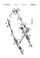
- FIG. 1 is a longitudinal cross section through a tape drive with a removable magazine holding four tape cassettes
- FIG. 2 is a perspective view of the cassette magazine after removal from the housing and tape drive with the cassettes removed;
- FIG. 3 is a top view of the magazine of FIG. 2;
- FIG. 4 is a view of the right side of the magazine of FIG. 2 with portions of the side wall removed to show the interior construction;
- FIG. 5 is a section along line 5--5 of FIG. 3;
- FIG. 6 is a cross section along line 6--6 of FIG. 3 with the cassettes on the upper deck advanced one position to the right and those on the lower deck one position to the left, which is the normal or "home" position of the cassettes when the magazine is removed from the tape drive;
- FIG. 7 is a cross section along line 7--7 of FIG. 3 with the tape cartridges removed;
- FIG. 8 is a partial cross section along line 8--8 of FIG. 4;
- FIG. 9 is a cross section along line 9--9 of FIG. 8;
- FIG. 10 is a section along line 10--10 of FIG. 4;
- FIG. 11 is a partial cross section similar to FIG. 1 showing the gripper engaging a cassette in the pick-up position
- FIG. 12 is a schematic sectional view generally along line 6--6 of FIG. 3 with the cassettes removed and the cassette transfer mechanism at the maximum back stroke, the pick-up position for the front cassette;
- FIG. 13 is a schematic view similar to FIG. 12 with the upper and lower cassette transfer mechanism at the maximum forward stroke, the home position for the cassettes;
- FIG. 14 is a partial perspective view illustrating the operation of the cassette transfer mechanism
- FIG. 15 is a partial perspective view illustrating the operation of the mechanism for transferring cassettes from the upper to the lower deck
- FIG. 16 is a top view similar to FIG. 1 with the magazine and tape drive mechanism removed;
- FIG. 17 is a cross section along line 17--17 of FIG. 16;
- FIG. 18 is a cross section along line 18--18 of FIG. 16;
- FIG. 19 is a cross section along line 19--19 of FIG. 16;
- FIG. 20 is a cross section along line 20--20 of FIG. 19;
- FIG. 21 is a partial cross section along line 21--21 of FIG. 19 with the cassette gripper in its closed position;
- FIG. 22 is a partial cross section along line 21--21 of FIG. 19 with the cassette gripper in its open position;
- FIG. 23 is a partial cross section along line 23--23 of FIG. 19 with the cassette gripper in its closed position;
- FIG. 24 is a partial cross section along line 24--24 of FIG. 16;
- FIG. 25 is a partial cross section along line 25--25 of FIG. 16;
- FIG. 26 is an exploded perspective view illustrating parts of the mechanism for opening and closing the cassette gripper
- FIG. 27 is a partial perspective view showing the cassette gripper transport mechanism
- FIG. 28 is a partial diagrammatic view illustrating the direction control mechanism for transporting the cassette gripper
- FIG. 29 is a top view of the bottom cover of the magazine with the cassettes removed;
- FIG. 30 is an elevational view of the gripper assembly
- FIG. 31 is a diagrammatic rear view of the gripper opening and closing mechanism along line 31--31 of FIG. 30;
- FIG. 32 is a face view of the lead nut showing the angular slot
- FIG. 33 is a face view of an internal control member for opening and closing the gripper
- FIG. 34 is a diagrammatic top view of the cassette gripper
- FIG. 35 is a partial sectional view illustrating the slip clutch for use in both the cassette drive mechanism and in the motion control of the gripper;
- FIG. 36 is an exploded perspective view illustrating details of the slip clutch of FIG. 34;
- FIG. 37 is a cross section of the assembled slip clutch showing the bushing and flexible sleeve
- FIG. 38 is a cross section of the bushing
- FIG. 39 is a cross section of the flexible sleeve before deformation.
- FIG. 40 is an exaggerated view of the flexible sleeve after the preassembly deformation.
- a conventional tape drive is mounted in a housing 4 along with a removable magazine, generally indicated at 6, that stores the tape cassettes 8.
- the cassette magazine 6 is locked in position within the housing 4 by a lever 12.
- the tape drive 2 is conventional in every respect and the loading and unloading functions associated with the magazine 6 are modified in each case to adapt them to the particular dimensions and characteristics of the tape drive.
- the magazine 6 is positioned below the tape drive 2 and the entrance to the tape drive, for loading and unloading the cassettes, faces the forward end of the housing 4 (toward the left as viewed in FIG. 1).
- the "entrance position" where casettes are delivered by the tape drive 2 for transfer to the magazine 6 is indicated at 15.
- the operation of the loading and unloading functions of the tape drive and the magazine is controlled by conventional electronic circuits of known design and are not described here.
- the magazine 6 holds four cassette tapes 8, although magazines holding six or more cassettes can be constructed in the same manner as described here merely by lengthening the magazine.
- an unrecorded cassette is loaded from the magazine into the tape drive where it records back-up date until the tape is fully recorded.
- the tape cassette is then expelled from the tape drive and, when the presence of a tape cassette is sensed at the entrance of the tape drive 2, the cassette is automatically replaced in the magazine 6.
- the cassettes in the magazine are then shifted in position and a new unrecorded tape cassette is placed in the tape drive 2. This process continues until all four of the tape cassettes are fully recorded.
- a signal alerts the operator for replacement of the magazine.
- the entire operating procedures are automatic under the control of known electronic circuits.
- cassettes 8A, 8B, 8C and 8D are positioned in the magazine 6.
- the cassettes are lying flat in two decks one above the other.
- the cassettes 8A and 8B are on the upper deck and cassettes 8C and 8C are on the lower deck.
- the cassette 8A is shown in the "pick-up" position on the upper deck. It is from this position that a cassette is removed from or replaced in the magazine.
- the space, indicated at 14, directly beneath cassette 8A is vacant.
- the two cassettes 8A and 8B are moved together horizontally one cassette space toward the rear end of the magazine 6, indicated at 16R.
- the cassettes 8C and 8D are transferred horizontally one cassette width toward the front end of the magazine, indicated at 16F, so that the cassette 8C occupies the position directly beneath the pick-up position vacated by cassette 8A. This is the "home" position of the cassettes inside the magazine when the magazine is removed from the tape drive.
- the cassette C is then transferred vertically from the lower to the upper deck to occupy the pick-up position.
- the cassette 8B is transferred vertically from the upper to the lower deck into the empty space vacated by the cassette 8D.
- cassettes are transferred to and from the tape drive 2 by a cassette gripper, generally indicated at 18, which is shown in FIG. 1 in solid lines at its load/unload position at the entrance 15 to the tape drive 2. Other positions assumed by the cassette gripper are shown in dotted outlines. The construction and operation of the gripper 18 will be described more fully later.
- the cassettes in the bottom deck rest on the floor 20 of the magazine with the cassettes positioned beneath support members 21 and 21A (FIG. 9). These supports provide support for the center cassette position of the upper deck, but are terminated at the front and rear edges of that position to permit transfer of the cassettes from one deck to another at the ends of the magazine.
- a pair of rams 32UL and 32UR (FIG. 14) are positioned in grooves in the walls and bottom and top covers of the magazine to reciprocate longitudinally.
- the ram 32UR carries a projecting tab 33UR at the end that engages the rear end of the cassette in the pick-up position, as the ram moves toward the end 16R (to the right as viewed in FIG. 14), the tab 33UR (along with a similar tab on the opposing ram 32UL) pushes the upper cassette in the pick-up position toward the right.
- the ram 32UL is a mirror image of the ram 32UR.
- a rack 34UR on the bottom of the ram engages the top of a pinion 36R (see also FIGS. 12, 13 and 15).
- the pinion 36R is connected by a shaft 37 to a similar pinion 36L on the opposite side of the magazine and to a drive gear 38 on the outside of the magazine.
- the gear 38 is hidden in a recess in the side of the magazine (see also FIG. 2) so that the gear cannot be manually tampered with or accidentally rotated.
- a groove 39 in the magazine sidewall extends from the gear 38 to the rear of the magazine to permit a pinion drive (to be described later) to engage the gear 38. This arrangement permits easy withdrawal and replacement of the magazine.
- the gear 38 is driven in a clockwise direction, as viewed in FIGS. 2 and 14, to move the upper deck cassettes toward the rear of the magazine.
- a spring loaded pawl 40UL in the side of the ram 32UL (FIG. 14) and a similar pawl 40UR (not visible in FIG. 14) in the inner surface of the ram 32UR engage the rear edge of the adjacent cassette.
- the drive is reversed and the rams 32UR and 32UL return toward the forward end of the magazine.
- the spring mounted pawls 40UL and 40UR pass freely over the cassette during the return stroke.
- Two additional pawls 40CA and 40CB (FIG.
- the tabs 33UR and 33UL are also the spring mounted to allow the vertical transfer of the bottom front cassette into the pick-up position during the return stroke.
- one cassette on the upper deck is moved toward the rear end 16R of the magazine 6, and one cassette on the lower deck moves toward the forward end 16F.
- the cassette in the upper deck farthest to the rear is pushed downward into the vacant space on the lower deck and the forward cassette on the lower deck is forced upwardly into the pick-up position on the upper deck.
- an arm 48UR (FIGS. 12-14) is pivotally mounted by a pin 49UR to the inner wall of the magazine housing.
- a cassette push plate 50UR is secured to a slide 51UR that is mounted for vertical movement in a groove in the magazine housing.
- a pin 52UR engages a slot 53UR in the arm 48UR to secure the slide 51UR to the arm 48UR.
- the push plate 50UR is nested inside the top cover and rests on the top of the cassette on the upper deck nearest the end 16R.
- a pin 54UR on the arm 48UR slidably engages a ramp groove 56UR in the side of the ram 32UR.
- the pin 54UR slides in a linear portion of the groove 56UR that is level with a fixed pin 49UR.
- the arm 48UR is thus maintained in a horizontal position during that motion of the ram, keeping the cassette push plate 50UR nested inside the top cover allowing the cassette to slide under it during the forward stroke.
- the pin 54UR engages a ramp portion of the groove 56UR that forces the pin 54UR downward causing the arm 48UR to pivot about the fixed pin 49UR.
- the plate 50UR pushed one end of the cassette downward to the lower deck.
- FIGS. 12 and 13 show schematically the mechanism on the left side of the magazine 6 as viewed in FIG. 2.
- the ram 32LL (and the opposite ram 32LR, (now shown in this view) are at the far front position having moved the lower deck cassettes to the front of the magazine.
- the ram 32LL is driven by the same rack and pinion arrangement as in the upper deck except the racks are on the upper edge and engage the lower sides of the pinions 36R and 36L (See also FIG. 14).
- the drive shaft 37 is driven in a counter clockwise direction, the ram 32LL is driven toward the rear of the magazine, while the cassettes are prevented from mvoing by resilient pwals 57FA and 57FB (see FIG. 8, not shown in FIG. 29) formed in the floor of the magazine and extending upward into the path of the lower-deck cassettes.
- These pawls have a sloping upper surface so that the pawls are deflected permit the cassettes to slide over them when moving toward the front of the magazine, but preventing movement of the cassettes in the opposite direction.
- the pin 54LL extending from the arm 48LL rides in a linear portion of the ramp groove 56LL in the ram 32LL. Since the linear portion of the groove 56LL is in horizontal alignment with the fixed pivot pin 49LL, the arm 48LL remains horizontal until the ramp portion of the groove 56LL, reaches the pin 54LL at which time the pin 54LL is forced upwardly to pivot the arm 48LL about the fixed pin 49LL to the position shown in FIG. 12.
- the arm 48LL carries a push plate 50LL that, in cooperation with an identical lift arrangement on the opposite side of the magazine, forces the cassette upward into the pick-up position on the upper deck.
- the push plate 50LL and the opposite one 50LR are brought quickly back to nesting in recesses 76 in the floor of the magazine to allow the newly arriving cassette to slide over them without interference.
- the guiding slots 74 in each side of the magazine maintain the sliding motion of the push plates 50LL and 50LR straight up and down during the cassette transfer (see also FIG. 15).
- two elongated cylindrical pawls 58 are positioned in slots in opposite walls of the magazine.
- the pawl 58, as shown in FIG. 2, and an opposing pawl (not shown) in the opposite wall of the magazine 6 are spring biased inwardly so that the cassette can be easily pushed upward over the pawls by the push plates 50LL and 50LR, forcing the pawls inwardly into the retaining slots.
- the pawls provide sufficient support to prevent the cassette from dropping back to the lower deck.
- two similar pawls (now shown), similarly biased by springs, prevent a cassette on the upper deck at the rear of the magazine from falling by its own weight to the lower deck.
- the magazine may be operated in any position and it is not necessary to have a full complement of cassettes: the transfer functions can be performed with only one cassette in the magazine.
- the horizontal and vertical transfer of the cassettes 8 within the magazine 6 is powered by an electric motor 79 (FIG. 27); the gripper 18 is opened and closed by an electric motor 80 (FIGS. 26 and 27); and the gripper 18 is transferred between the pick-up position in the magazine 6 and the entrance to the tape drive 2 by a motor 81 (FIG. 27).
- FIGS. 16 through 25 show details of the robotic mechanism that transports the cassettes between the pick-up position of the magazine 6 and the entrance position of the tape drive 2.
- the cassette gripper 18 consists of two rigid upper ears 82A and 82B (see FIGS. 16, 27 and 29), that engage the upper surface of the cassette at two spaced contact points, and a rotatable stiff wire spring finger 86 that engages the lower surface of the cassette near the rear edge.
- the finger 86 which is biased by a spring member 90 (FIG. 27) toward its open position, is secured to an actuating shaft 88 supported by a bearing 92 (FIG. 34) integral with a supporting cantilever arm 94.
- the finger 86 presses upwardly against the undersurface of the cassette and forces it upwardly against the ears 82A and 82B. These ears fit closely against the surface of the cassette and the finger 86 is adjacent the very rear edge of the cassette allowing the cassette to be placed far enough into the tape deck opening to accommodate the cassette handling mechanisms of the various tape deck designs.
- the cassette which may contain valuable information, be prevented from being damaged even in the event of a malfunction of the mechanisms. If an object strikes the cassette while it is being gripped, the flexing of the spring biased finger 86 will permit the cassette to be removed from the gripper without damage to the cassette.
- the arm 94 is supported by a slide bar 98 (FIG. 27) that is slidably mounted in a vertical slot 102 in a stanchion, generally indicated at 104, that is itself mounted for horizontal movement along a track 106 (FIG. 30) secured to the base of the housing 4 (FIG. 1).
- the shaft 88 extends beyond the slide bar 98 (FIG.
- FIG. 21 illustrates the position of the arm 114 when the gripper finger 86 is in its closed position.
- the roller 116 rolls along the wall 115 of the U-shaped recess in the control member 110 to maintain the gripper in closed position.
- the arm 114 rotates clockwise, as shown in FIG. 22, driven by the spring 90, causing the the finger 86 to open and release the cassette.
- the roller 116 rides on the recess wall 115 of the control member 110 and the open position of the gripper finger 86 is unaffected.
- a number of laterally displaced ball bearings 118 are positioned between the upper and lower ends of the control member 110 and the adjacent surfaces of the transverse opening 112 in the stanchion 104.
- a roller 122 is mounted on the end of a short shaft 123 (FIG. 30) extending from the rear surface of the control member 110 through a horizontal slot.
- the roller 122 is positioned in a slot 124 in the surface of a lead nut 126.
- the slot 124 extends at an angle from the vertical (FIG. 32) so that as the nut 126 moves vertically the control member 110 is shifted horizontally.
- the nut 126 is supported for vertical movement by a pair of support rods 128A and 128B (FIGS. 26 and 31) that extend between two platforms 132U and 132L formed integrally with the stanchion 104.
- a lead screw 134 in threaded engagement with the nut 126 extends from a bearing 136 in the platform 132U through an opening in the platform 132L and is connected to the drive shaft of the motor 80 that is secured to the platform 132L on the stanchion 104.
- the cassette gripper 18 can be lowered to engage a cassette in the pick-up position in the magazine 6.
- the motor 80 then drives the lead screw 134 to lift the nut 126 vertically upward forcing the control member 110 to move sideways to the position shown in FIG. 21 closing the gripper finger 86 on the cassette.
- the control member 110 may then be lifted vertically to raise the cassette to the level of the entrance position 15 of the tape drive 2. The cassette remains firmly gripped during this vertical transition.
- the nut 126 merely strikes the upper platform 132U at the top of the movement or the platform 132L at the bottom of the stroke.
- the load on the motor 80 is increased and the current drawn by the motor increases accordingly. This increase in motor current is sensed by known circuit means (not shown) to interrupt the power to the motor.
- two similar O-rings 138C and 138D are positioned around the lower portions of the support rods 128A and 128B between the nut 126 and the lower motion limiting platform 132L.
- the gripper 18 When the tape drive 2 ejects a cassette to the gripper 18 at the entrance position, the presence of the cassette is sensed by a conventional beam sensor, indicated diagrammatically at 139 in FIG. 27. When the sensor 139 is activated, the gripper 18 closes upon the cassette and transports it the pick-up position of the magazine 6. In moving from the entrance position to the pick-up position in the magazine, the gripper arm 94 follows an L-shaped path in which the cassette is moved horizontally away from the tape drive 2 and then vertically downward to the pick-up position. Conversely, in transferring a cassette from the pick-up position in the magazine, the gripper arm 94 moves vertically upward and then horizontally to the entrance position.
- the stanchion 104 including the motor 80 and the gripper opening and closing mechanism, are moved horizontally.
- An L-shaped guiding track 140 (FIGS. 27 and 28) guides the cassette gripper arm 94 along its vertical and horizontal paths without possibility of failure.
- a roller 141 rotates on a stud 142 that is secured to the slide bar 98 (diagrammatically illustrated in FIG. 27) that is integral with the cantilever gripper arm 94 and slides vertically up and down inside the stanchion 104.
- the stud 142, and the roller 141 must move vertically from the position indicated at A in FIG. 28 to the position indicated at B, then horizontally from position B to position C, carrying with it the slide bar 98 and gripper arm 94.
- This motion is produced by a rigid 3-point lever 144 that is mounted on three triangularly positioned connection points for horizontal and rotary movement.
- One of the three point connections is made by the stud 142 and roller 141 to the slide bar 98 near its base.
- the roller 142 rides along the edge of an L-shaped guide track 140.
- the lever 144 is pivotally connected by a stud 148 to a base 152 that forms an integral part of the stanchion 104 and is slidably mounted on the track 106 (FIG. 30).
- the connection point at the stud 148 is restricted to horizontal movement.
- the third of the three point connections is pivotally connected by a stud 154 to a driving ram 156 shown in FIG. 27 and indicated diagrammatically by the horizontal line 156 in FIG. 28.
- the roller 141 is free to move horizontally on the track 140 pulled by the stud 154 that is moving back to position C'.
- the lever 144 and the stud 148 are also moving backward to the position indicated at C". This is the maximum backward position with the gripper 18 at the tape drive entrance position 15 or, as will be explained later, slightly to the left of the entrance position 15 as viewed in FIG. 27 and to the right of it as viewed in FIG. 1.
- Reverse motion of the ram 156 will move the stud 154 from position C' to B' while the roller 141 is rolling horizontally on the track 146 until it reaches the position B. It is then free to drop vertically down to position A.
- the slide bar 98 and the gripper arm 18 are moved so that the gripper is in the pick-up position in the magazine 6.
- the track 146 is a simple piece of flat sheet metal positioned to guide the path of the roller 141.
- the horizontal movement of the ram, 156 is provided by the electric motor 81 through a pinion 168 (FIGS. 16, 17, 24 and 27) driven by a conventional worm gear arrangement generally indicated at 172A (FIG. 25) that drives a rack on the bottom of the ram 156.
- a gear 174 is connected to an output shaft 175 through a slip clutch, generally indicated at 176 in FIG. 25, that limits the maximum torque applied to the pinion 168.
- This allows the stroke of the ram 156 to be limited by hard stops while eliminating the possibility of mechanical damage.
- the drive is actuated in one direction and continues until the ram 156 is blocked from further movement.
- the increased load on the motor 81 increases the current through the motor and this increase actuates an electronic circuit of conventional type (not shown) that interrupts the current to the motor.
- a worm 178 driven by the motor 81 drives a worm gear 180 that is mounted to rotate freely on an output shaft 175 connected to the ram drive pinion 168.
- a flexible sleeve 186 is rotatably mounted on a bushing 188 that is keyed to the output shaft 175.
- the worm gear 180 engages and drives the flexible sleeve 186 by means of two notches 192A and 192B and engaging tabs 194 (only one of which is shown in FIG. 36).
- the flexible sleeve 186 (FIG. 39) is formed initially with an inner diameter D2 that is slightly larger than the outside diameter D1 of the bushing 188 (FIG. 38), that is, the diameter of the sleeve is such that if it were perfectly round there would be negligible friction between the sleeve and the bushing 188.
- the flexible sleeve 186 Prior to assembly, however, the flexible sleeve 186 is permanently deformed, as by flattening to form a generally oval shape, so that opposite points on the perimeter are pressed inwardly so that the smallest diameter H (FIG. 40) is significantly, but only slightly, less than the Diameter D1 of the bushing 188.
- the flexible sleeve 186 is formed of beryllium bronze, stainless steel or other spring type metal.
- the bushing 188 is preferably formed of a wear resistant plastic such as nylon.
- the application of these forces produces a frictional contact between the two surfaces that allows a torque to be transmitted between the flexible sleeve 186 and the bushing 188.
- the magnitude of the maximum torque that can be transmitted is a function of the magnitude of the forces F and F'. The magnitude of the forces depends, among other factors, on materials, size, and the degree of deformation imparted to the flexible sleeve prior to its assembly on the bushing 188. When the torque reaches its maximum value, slippage occurs between the sleeve 186 and the bushing 188 thus preventing an excessive torque from being transmitted.
- the spring rate of the material that forms the flexible sleeve will maintain the forces F and F' at a near constant value to provide a relatively stable maximum torque transmission.
- the torque transmission level can be set simply by controlling the degree of deformation of the flexible sleeve 186. Once set, the slip clutch needs no further adjustment and is relatively tamper proof.
- the gripper 18 transfers the cassette from the pick-up position in the magazine to the entrance position 15.
- the rear end of the drive ram 156 (FIG. 27) closes a switch 195 that opens the gripper 18.
- the gripper remains open as the ram 156 continues to move toward the left as viewed in FIG. 27.
- the gripper 18 inserts the cassette into the tape drive 2 until the stanchion 104 strikes an abutment causing the current to the motor 81 to be interrupted. At this point, the cassette is "swallowed" by the tape drive mechanism 2.
- the motor 81 is then actuated to reverse the motor 81 and move the gripper away from the tape drive 2 until the switch 195 is opened by movement of the ram 156 and disconnects the motor 81.
- the switch 195 is mechanically positioned in the path of the ram 156 at a point that will cause the gripper 18 to open during the motion of the gripper toward the tape drive 2 before "swallowing" of the cassette by the tape drive mechanism occurs.
- the switch 195 stops the return movement of the gripper at a point where the cassette will be positioned to receive a cassette ejected from the tape drive.
- the gripper remains in this position until the sensor 139 indicates that a cassette has been ejected by the tape drive 2.
- the gripper arm 18 is then closed and the cassette is transferred to the pick-up position in the magazine 6.
- worm gear arrangement generally indicated at 172A (FIG. 24) to a magazine drive pinion 196 (see also FIG. 16).
- the worm gear drive arrangement may be identical with the worm gear arrangement 172.
- a slip clutch, generally indicated at 176A, is included in the drive train and is identical to the slip clutch 176, already described.
- the pinion 196 is positioned so that when the magazine 6 is inserted into the housing 4, the pinion passes along the groove 39 in the wall of the magazine and, when the magazine is fully inserted, engages the drive gear 38 on the side of the magazine.
Abstract
Description
Claims (37)
Priority Applications (3)
| Application Number | Priority Date | Filing Date | Title |
|---|---|---|---|
| US07/727,647 US5184260A (en) | 1990-07-19 | 1991-07-09 | Magnetic tape drive with integral multiple-cassette removable magazine |
| US07/909,061 US5345349A (en) | 1990-07-19 | 1992-07-02 | Magazine latching and ejection mechanism for a cassette autoloader |
| US07/909,066 US5319991A (en) | 1990-07-19 | 1992-07-02 | Motor coupling with angular compliance |
Applications Claiming Priority (3)
| Application Number | Priority Date | Filing Date | Title |
|---|---|---|---|
| US55557690A | 1990-07-19 | 1990-07-19 | |
| US67991091A | 1991-04-03 | 1991-04-03 | |
| US07/727,647 US5184260A (en) | 1990-07-19 | 1991-07-09 | Magnetic tape drive with integral multiple-cassette removable magazine |
Related Parent Applications (2)
| Application Number | Title | Priority Date | Filing Date |
|---|---|---|---|
| US55557690A Continuation-In-Part | 1990-07-19 | 1990-07-19 | |
| US67991091A Continuation-In-Part | 1990-07-19 | 1991-04-03 |
Related Child Applications (2)
| Application Number | Title | Priority Date | Filing Date |
|---|---|---|---|
| US07/909,066 Continuation-In-Part US5319991A (en) | 1990-07-19 | 1992-07-02 | Motor coupling with angular compliance |
| US07/909,061 Continuation-In-Part US5345349A (en) | 1990-07-19 | 1992-07-02 | Magazine latching and ejection mechanism for a cassette autoloader |
Publications (1)
| Publication Number | Publication Date |
|---|---|
| US5184260A true US5184260A (en) | 1993-02-02 |
Family
ID=27415704
Family Applications (1)
| Application Number | Title | Priority Date | Filing Date |
|---|---|---|---|
| US07/727,647 Expired - Fee Related US5184260A (en) | 1990-07-19 | 1991-07-09 | Magnetic tape drive with integral multiple-cassette removable magazine |
Country Status (1)
| Country | Link |
|---|---|
| US (1) | US5184260A (en) |
Cited By (23)
| Publication number | Priority date | Publication date | Assignee | Title |
|---|---|---|---|---|
| US5469310A (en) * | 1989-11-13 | 1995-11-21 | Wangdat, Inc. | Automated cassette loader |
| EP0725398A2 (en) * | 1995-02-03 | 1996-08-07 | Sony Corporation | Auto-loading system for recording medium cartridge |
| US5638348A (en) * | 1994-03-08 | 1997-06-10 | Hyundai Electronics Industrial Co., Ltd. | Automatic cartridge-exchanging apparatus and method for mini-disk player |
| WO1998021376A1 (en) * | 1996-11-15 | 1998-05-22 | Brush Wellman Inc. | High strength cast aluminum-beryllium alloys containing magnesium |
| USD415126S (en) * | 1998-07-24 | 1999-10-12 | Exabyte Corporation | Cartridge library |
| US6144521A (en) * | 1997-11-14 | 2000-11-07 | Exabyte Corporation | Tape cartridge magazine with structure to prevent improper loading of cartridges |
| US6160678A (en) * | 1992-05-15 | 2000-12-12 | Hewlett-Packard Company | Autochanger for storing and transferring multiple media items, such as tape cartridges, relative to a read/write mechanism |
| US6175467B1 (en) | 1997-11-14 | 2001-01-16 | Exabyte Corporation | Data cartridge library with cartridge transport assembly |
| US6312534B1 (en) | 1994-04-01 | 2001-11-06 | Brush Wellman, Inc. | High strength cast aluminum-beryllium alloys containing magnesium |
| US6462900B1 (en) | 2000-11-09 | 2002-10-08 | Exabyte Corporation | Cartridge picker robot with ribbon cable for cartridge library |
| US6466396B1 (en) | 2000-11-09 | 2002-10-15 | Exabyte Corporation | Cartridge library |
| US6473261B1 (en) | 2000-11-09 | 2002-10-29 | Exabyte Corporation | Cartridge overinsertion protection for cartridge library |
| US6612499B2 (en) | 2002-01-24 | 2003-09-02 | Exabyte Corporation | Calibration cartridge for automated cartridge library and method of using same |
| US6781789B2 (en) * | 2001-09-28 | 2004-08-24 | Storage Technology Corporation | Dual cartridges storage array cell for data storage |
| US20070058287A1 (en) * | 2005-09-15 | 2007-03-15 | Kenichi Hori | Media cartridge autoloader |
| US20080282281A1 (en) * | 2007-05-11 | 2008-11-13 | White Christopher M | Cartridge engagement apparatus and method for cartridge library |
| US20080278847A1 (en) * | 2007-05-11 | 2008-11-13 | Barkley John A | Method and apparatus for positioning drives in cartridge library |
| US20080282275A1 (en) * | 2007-05-11 | 2008-11-13 | Zaczek Thomas E | Entry/exit port method and apparatus for cartridge library |
| US20080278839A1 (en) * | 2007-05-11 | 2008-11-13 | Tandberg Data Corporation | Multi-dimensional transport method and apparatus for cartridge library |
| US20080282278A1 (en) * | 2007-05-11 | 2008-11-13 | Tandberg Data Corporation | Transport method and apparatus for cartridge library |
| US20090040653A1 (en) * | 2007-08-10 | 2009-02-12 | Andrew Stuart Green | Variable spring-force mechanism for advancing tape media cartridges in a deep slot cell |
| US7518822B1 (en) * | 2006-03-13 | 2009-04-14 | International Business Machines Corporation | Data storage cartridge gripper with deep-reach |
| US20110181980A1 (en) * | 2010-01-22 | 2011-07-28 | Fujitsu Limited | Library apparatus |
Citations (9)
| Publication number | Priority date | Publication date | Assignee | Title |
|---|---|---|---|---|
| US3603597A (en) * | 1969-04-25 | 1971-09-07 | Bell & Howell Co | Tape recorder |
| US3658193A (en) * | 1969-11-21 | 1972-04-25 | Data Instr Co | Magnetic tape cassette changer |
| US3797923A (en) * | 1972-10-10 | 1974-03-19 | Bolex Int Sa | Cinematographic projector |
| US3848264A (en) * | 1973-06-08 | 1974-11-12 | C Wilson | Magnetic tape cartridge changer |
| US3883895A (en) * | 1972-06-14 | 1975-05-13 | Victor Company Of Japan | Cartridge changer |
| US4071857A (en) * | 1976-09-10 | 1978-01-31 | Dictaphone Corporation | Cassette changer apparatus |
| US4614474A (en) * | 1983-08-31 | 1986-09-30 | Sony Corporation | Device for exchanging disks |
| US4860133A (en) * | 1986-04-11 | 1989-08-22 | Ampex Corporation | Cassette bin structure including a bin section for loading and unloading cassettes |
| US5089920A (en) * | 1989-11-13 | 1992-02-18 | Wangdat, Inc. | Loader mechanism for tape cartridge systems |
-
1991
- 1991-07-09 US US07/727,647 patent/US5184260A/en not_active Expired - Fee Related
Patent Citations (9)
| Publication number | Priority date | Publication date | Assignee | Title |
|---|---|---|---|---|
| US3603597A (en) * | 1969-04-25 | 1971-09-07 | Bell & Howell Co | Tape recorder |
| US3658193A (en) * | 1969-11-21 | 1972-04-25 | Data Instr Co | Magnetic tape cassette changer |
| US3883895A (en) * | 1972-06-14 | 1975-05-13 | Victor Company Of Japan | Cartridge changer |
| US3797923A (en) * | 1972-10-10 | 1974-03-19 | Bolex Int Sa | Cinematographic projector |
| US3848264A (en) * | 1973-06-08 | 1974-11-12 | C Wilson | Magnetic tape cartridge changer |
| US4071857A (en) * | 1976-09-10 | 1978-01-31 | Dictaphone Corporation | Cassette changer apparatus |
| US4614474A (en) * | 1983-08-31 | 1986-09-30 | Sony Corporation | Device for exchanging disks |
| US4860133A (en) * | 1986-04-11 | 1989-08-22 | Ampex Corporation | Cassette bin structure including a bin section for loading and unloading cassettes |
| US5089920A (en) * | 1989-11-13 | 1992-02-18 | Wangdat, Inc. | Loader mechanism for tape cartridge systems |
Cited By (33)
| Publication number | Priority date | Publication date | Assignee | Title |
|---|---|---|---|---|
| US5469310A (en) * | 1989-11-13 | 1995-11-21 | Wangdat, Inc. | Automated cassette loader |
| US6476999B1 (en) | 1992-05-15 | 2002-11-05 | Hewlett-Packard Company | Autochanger for storing and transferring multiple media items, such as tape cartridges, relative to a read/write mechanism |
| US6160678A (en) * | 1992-05-15 | 2000-12-12 | Hewlett-Packard Company | Autochanger for storing and transferring multiple media items, such as tape cartridges, relative to a read/write mechanism |
| US5638348A (en) * | 1994-03-08 | 1997-06-10 | Hyundai Electronics Industrial Co., Ltd. | Automatic cartridge-exchanging apparatus and method for mini-disk player |
| US6312534B1 (en) | 1994-04-01 | 2001-11-06 | Brush Wellman, Inc. | High strength cast aluminum-beryllium alloys containing magnesium |
| EP0725398A2 (en) * | 1995-02-03 | 1996-08-07 | Sony Corporation | Auto-loading system for recording medium cartridge |
| EP0725398A3 (en) * | 1995-02-03 | 1996-12-27 | Sony Corp | Auto-loading system for recording medium cartridge |
| US5793564A (en) * | 1995-02-03 | 1998-08-11 | Sony Corporation | Auto-loading system for interfacing a magazine of recording medium cartridges with a recording/reproducing apparatus |
| WO1998021376A1 (en) * | 1996-11-15 | 1998-05-22 | Brush Wellman Inc. | High strength cast aluminum-beryllium alloys containing magnesium |
| US6175467B1 (en) | 1997-11-14 | 2001-01-16 | Exabyte Corporation | Data cartridge library with cartridge transport assembly |
| US6229666B1 (en) | 1997-11-14 | 2001-05-08 | Exabyte Corporation | Data cartridge library having a pivoting cartridge transport |
| US6233111B1 (en) | 1997-11-14 | 2001-05-15 | Exabyte Corporation | Data cartridge library having a pivoting cartridge transport and a cartridge status indicator |
| US6236530B1 (en) | 1997-11-14 | 2001-05-22 | Exabyte Corporation | Data cartridge library having a pivoting cartridge transport |
| US6144521A (en) * | 1997-11-14 | 2000-11-07 | Exabyte Corporation | Tape cartridge magazine with structure to prevent improper loading of cartridges |
| USD415126S (en) * | 1998-07-24 | 1999-10-12 | Exabyte Corporation | Cartridge library |
| US6473261B1 (en) | 2000-11-09 | 2002-10-29 | Exabyte Corporation | Cartridge overinsertion protection for cartridge library |
| US6466396B1 (en) | 2000-11-09 | 2002-10-15 | Exabyte Corporation | Cartridge library |
| US6462900B1 (en) | 2000-11-09 | 2002-10-08 | Exabyte Corporation | Cartridge picker robot with ribbon cable for cartridge library |
| US6781789B2 (en) * | 2001-09-28 | 2004-08-24 | Storage Technology Corporation | Dual cartridges storage array cell for data storage |
| US6612499B2 (en) | 2002-01-24 | 2003-09-02 | Exabyte Corporation | Calibration cartridge for automated cartridge library and method of using same |
| US20070058287A1 (en) * | 2005-09-15 | 2007-03-15 | Kenichi Hori | Media cartridge autoloader |
| US7518822B1 (en) * | 2006-03-13 | 2009-04-14 | International Business Machines Corporation | Data storage cartridge gripper with deep-reach |
| US20080278839A1 (en) * | 2007-05-11 | 2008-11-13 | Tandberg Data Corporation | Multi-dimensional transport method and apparatus for cartridge library |
| US20080282275A1 (en) * | 2007-05-11 | 2008-11-13 | Zaczek Thomas E | Entry/exit port method and apparatus for cartridge library |
| US20080278847A1 (en) * | 2007-05-11 | 2008-11-13 | Barkley John A | Method and apparatus for positioning drives in cartridge library |
| US20080282278A1 (en) * | 2007-05-11 | 2008-11-13 | Tandberg Data Corporation | Transport method and apparatus for cartridge library |
| US20080282281A1 (en) * | 2007-05-11 | 2008-11-13 | White Christopher M | Cartridge engagement apparatus and method for cartridge library |
| US7777985B2 (en) | 2007-05-11 | 2010-08-17 | Tandberg Data Corporation | Transport method and apparatus for cartridge library utilizing cam slot and follower for moving a robot carriage |
| US7777986B2 (en) | 2007-05-11 | 2010-08-17 | Tandberg Data Corporation | Multi-dimensional transport method and drive subsystems in a cartridge library apparatus |
| US20090040653A1 (en) * | 2007-08-10 | 2009-02-12 | Andrew Stuart Green | Variable spring-force mechanism for advancing tape media cartridges in a deep slot cell |
| US7894157B2 (en) * | 2007-08-10 | 2011-02-22 | International Business Machines Corporation | Variable spring-force mechanism for advancing tape media cartridges in a deep slot cell |
| US20110181980A1 (en) * | 2010-01-22 | 2011-07-28 | Fujitsu Limited | Library apparatus |
| US8488269B2 (en) * | 2010-01-22 | 2013-07-16 | Fujitsu Limited | Library apparatus |
Similar Documents
| Publication | Publication Date | Title |
|---|---|---|
| US5184260A (en) | Magnetic tape drive with integral multiple-cassette removable magazine | |
| US5274620A (en) | Compact disc handling mechanism | |
| US5469310A (en) | Automated cassette loader | |
| US4918548A (en) | Cartridge loader | |
| EP0402394B1 (en) | Automatic magnetic tape cartridge stack loader for tape drive systems | |
| JP3633928B2 (en) | Auto changer | |
| JP3338442B2 (en) | Autoloader for magnetic tape cartridge | |
| US4071857A (en) | Cassette changer apparatus | |
| EP0623924A2 (en) | Magazine drawer manipulation system for a data carrier loader | |
| US5045958A (en) | Positioner for magnetic tape cartridge magazine | |
| US4092685A (en) | Cassette changer apparatus having priority eject | |
| US3756608A (en) | Automatic cassette changer | |
| US4807066A (en) | Cassette changer for magnetic recording-reproduction apparatus | |
| US5144506A (en) | Cassette loader having simultaneous pusher and gripper movement | |
| EP0467187A2 (en) | Magnetic tape drive with integral multiple-cassette removable magazine | |
| US4099209A (en) | Electronic control system for multiple cassette record and/or playback apparatus | |
| US5128817A (en) | Tape drive autoloader apparatus for 8 mm magnetic tape cartridges | |
| US6870703B2 (en) | Dual feed through cassette transfer apparatus | |
| US20020044765A1 (en) | Method and apparatus for continuous feed of disks for recording digital video signals and authenticating the digitally recorded disks | |
| DE69637456T2 (en) | Playback device for recording media | |
| US5247407A (en) | Disk loading system | |
| EP0569636A1 (en) | Autochanger | |
| KR950010967B1 (en) | Cd auto-changer player | |
| JPH0278053A (en) | Cassette automatic exchanger for memory disk | |
| JPH0470710B2 (en) |
Legal Events
| Date | Code | Title | Description |
|---|---|---|---|
| FEPP | Fee payment procedure |
Free format text: PAYOR NUMBER ASSIGNED (ORIGINAL EVENT CODE: ASPN); ENTITY STATUS OF PATENT OWNER: SMALL ENTITY |
|
| AS | Assignment |
Owner name: ENCYNOVA INC., COLORADO Free format text: ASSIGNMENT OF ASSIGNORS INTEREST.;ASSIGNOR:PIERRAT, MICHEL A.;REEL/FRAME:006376/0192 Effective date: 19921105 |
|
| CC | Certificate of correction | ||
| AS | Assignment |
Owner name: HASTINGS PORK CORPORATION, COLORADO Free format text: ASSIGNMENT OF ASSIGNORS INTEREST;ASSIGNOR:ENCYNOVA, INC.;REEL/FRAME:006969/0244 Effective date: 19940222 Owner name: ANDREW, WILLIAM V., ARIZONA Free format text: SUMMARY OF CONDITIONAL ASSIGNMENT OF PATENT RIGHTS;ASSIGNOR:TAPEWORKS, L.P.;REEL/FRAME:006969/0258 Effective date: 19940421 Owner name: ANDREW, EDWARD J., JR., ILLINOIS Free format text: SECURITY INTEREST;ASSIGNOR:TAPEWORKS, L.P.;REEL/FRAME:006969/0254 Effective date: 19940414 Owner name: TAPEWORKS, L.P., COLORADO Free format text: ASSIGNMENT OF ASSIGNORS INTEREST;ASSIGNOR:TAPEWORKS, INC.;REEL/FRAME:006969/0251 Effective date: 19940330 Owner name: ANDREW, RICHARD G., TEXAS Free format text: SECURITY INTEREST;ASSIGNOR:TAPEWORKS, L.P.;REEL/FRAME:006969/0254 Effective date: 19940414 Owner name: WILLETT, KATHRYN A., ILLINOIS Free format text: SECURITY INTEREST;ASSIGNOR:TAPEWORKS, L.P.;REEL/FRAME:006969/0254 Effective date: 19940414 Owner name: TAPEWORKS, INC., COLORADO Free format text: ASSIGNMENT OF ASSIGNORS INTEREST;ASSIGNORS:THOMPSON, HAYDEN;HASTINGS PORK CORPORATION;REEL/FRAME:006969/0248 Effective date: 19940222 Owner name: ANDREW, LAUREL J., ARIZONA Free format text: SUMMARY OF CONDITIONAL ASSIGNMENT OF PATENT RIGHTS;ASSIGNOR:TAPEWORKS, L.P.;REEL/FRAME:006969/0258 Effective date: 19940421 Owner name: ANDREW, RICHARD G., ARIZONA Free format text: SUMMARY OF CONDITIONAL ASSIGNMENT OF PATENT RIGHTS;ASSIGNOR:TAPEWORKS, L.P.;REEL/FRAME:006969/0258 Effective date: 19940421 Owner name: ANDREW, EDITH G. AND EDWARD J., ARIZONA Free format text: SUMMARY OF CONDITIONAL ASSIGNMENT OF PATENT RIGHTS;ASSIGNOR:TAPEWORKS, L.P.;REEL/FRAME:006969/0258 Effective date: 19940421 Owner name: THOMPSON, HAYDEN, COLORADO Free format text: ASSIGNMENT OF ASSIGNORS INTEREST;ASSIGNOR:ENCYNOVA, INC.;REEL/FRAME:006969/0244 Effective date: 19940222 Owner name: ANDREW, EDWARD J., JR., ARIZONA Free format text: SUMMARY OF CONDITIONAL ASSIGNMENT OF PATENT RIGHTS;ASSIGNOR:TAPEWORKS, L.P.;REEL/FRAME:006969/0258 Effective date: 19940421 Owner name: WILLETT, KATHRYN A., ARIZONA Free format text: SUMMARY OF CONDITIONAL ASSIGNMENT OF PATENT RIGHTS;ASSIGNOR:TAPEWORKS, L.P.;REEL/FRAME:006969/0258 Effective date: 19940421 Owner name: ANDREW, LAUREL J., CALIFORNIA Free format text: SECURITY INTEREST;ASSIGNOR:TAPEWORKS, L.P.;REEL/FRAME:006969/0254 Effective date: 19940414 Owner name: ANDREW, WILLIAM, ARIZONA Free format text: SECURITY INTEREST;ASSIGNOR:TAPEWORKS, L.P.;REEL/FRAME:006969/0254 Effective date: 19940414 Owner name: ANDREW, EDITH G. AND EDWARD J., ILLINOIS Free format text: SECURITY INTEREST;ASSIGNOR:TAPEWORKS, L.P.;REEL/FRAME:006969/0254 Effective date: 19940414 |
|
| AS | Assignment |
Owner name: ANDREW, EDWARD J., ILLINOIS Free format text: ASSIGNMENT OF ASSIGNORS INTEREST;ASSIGNOR:TAPEWORKS, L.P.;REEL/FRAME:008059/0354 Effective date: 19960628 Owner name: ANDREW, LAUREL J., NEVADA Free format text: ASSIGNMENT OF ASSIGNORS INTEREST;ASSIGNOR:TAPEWORKS, L.P.;REEL/FRAME:008059/0354 Effective date: 19960628 Owner name: WILLETT, KATHRYN A., ILLINOIS Free format text: ASSIGNMENT OF ASSIGNORS INTEREST;ASSIGNOR:TAPEWORKS, L.P.;REEL/FRAME:008059/0354 Effective date: 19960628 Owner name: ANDREW, RICHARD G., TEXAS Free format text: ASSIGNMENT OF ASSIGNORS INTEREST;ASSIGNOR:TAPEWORKS, L.P.;REEL/FRAME:008059/0354 Effective date: 19960628 Owner name: ANDREW, WILLIAM V., ARIZONA Free format text: ASSIGNMENT OF ASSIGNORS INTEREST;ASSIGNOR:TAPEWORKS, L.P.;REEL/FRAME:008059/0354 Effective date: 19960628 Owner name: ANDREW, EDWARD J., JR., ILLINOIS Free format text: ASSIGNMENT OF ASSIGNORS INTEREST;ASSIGNOR:TAPEWORKS, L.P.;REEL/FRAME:008059/0354 Effective date: 19960628 |
|
| REMI | Maintenance fee reminder mailed | ||
| LAPS | Lapse for failure to pay maintenance fees | ||
| FP | Lapsed due to failure to pay maintenance fee |
Effective date: 19970205 |
|
| STCH | Information on status: patent discontinuation |
Free format text: PATENT EXPIRED DUE TO NONPAYMENT OF MAINTENANCE FEES UNDER 37 CFR 1.362 |