US5171276A - Knee joint prosthesis - Google Patents
Knee joint prosthesis Download PDFInfo
- Publication number
- US5171276A US5171276A US07/462,528 US46252890A US5171276A US 5171276 A US5171276 A US 5171276A US 46252890 A US46252890 A US 46252890A US 5171276 A US5171276 A US 5171276A
- Authority
- US
- United States
- Prior art keywords
- prosthesis
- cement
- fixation
- placed against
- tissue
- Prior art date
- Legal status (The legal status is an assumption and is not a legal conclusion. Google has not performed a legal analysis and makes no representation as to the accuracy of the status listed.)
- Expired - Lifetime
Links
Images

Classifications
-
- A—HUMAN NECESSITIES
- A61—MEDICAL OR VETERINARY SCIENCE; HYGIENE
- A61F—FILTERS IMPLANTABLE INTO BLOOD VESSELS; PROSTHESES; DEVICES PROVIDING PATENCY TO, OR PREVENTING COLLAPSING OF, TUBULAR STRUCTURES OF THE BODY, e.g. STENTS; ORTHOPAEDIC, NURSING OR CONTRACEPTIVE DEVICES; FOMENTATION; TREATMENT OR PROTECTION OF EYES OR EARS; BANDAGES, DRESSINGS OR ABSORBENT PADS; FIRST-AID KITS
- A61F2/00—Filters implantable into blood vessels; Prostheses, i.e. artificial substitutes or replacements for parts of the body; Appliances for connecting them with the body; Devices providing patency to, or preventing collapsing of, tubular structures of the body, e.g. stents
- A61F2/02—Prostheses implantable into the body
- A61F2/30—Joints
- A61F2/38—Joints for elbows or knees
- A61F2002/3895—Joints for elbows or knees unicompartimental
Definitions
- the present invention relates broadly to prosthetic implants, and more particularly, to prostheses for human joints, such as the knee, implantable by means of arthroscopic as well as open surgical techniques.
- the natural knee joint includes the bottom part of the femur, constituted by the two condyles, the lower parts of which bear upon the complementary shaped upper surface plateaus of the tibia through the intermediary of cartilage or meniscus. Connection through the knee is provided by means of ligaments which also provide joint stability and assist in absorbing stresses applied to the knee.
- the femur, cartilage and tibia are normally subjected to significant compression loading in supporting the weight of the body.
- Movement of the normal knee is not a true hinged joint about a single center but, rather, is a complex action including rocking, gliding and axial rotation.
- the rocking movement then changes to a combined sliding and pivoting movement wherein successive points on the femoral condyles slide forward on the tibial plateaus until full flexion is obtained.
- the flexion movement is polycentric, that is, about different centers which are not fixed in one position but lie in a somewhat spiral or polycentric pathway.
- Knee prostheses of the first category possess significant disadvantages in that they generally involve the removal of natural ligaments and only permit motion about a single axis as opposed to the controlled rotation and translation characteristic of a natural, healthy knee.
- Knee prostheses of the second type generally include femoral components secured to the condylar surfaces of the femur, typically having cylindrical bearing surfaces, and tibial components fixed to the tibial plateaus, the femoral components bearing against the upper surfaces of corresponding tibial components. Examples of prostheses of the latter type are shown in U.S. Pat. No. 4,470,158 to Pappas et al; U.S. Pat. No. 4,211,228 to Cloutier; U.S. Pat. No. 4,207,627 to Cloutier; and U.S. Pat. No. 3,953,899 to Charnley.
- unicompartmental knee replacement In addition to total knee replacement, unicompartmental knee replacement is known wherein a single compartment of the knee is surgically restored. Typically, the medial or lateral portion of the tibio-femoral joint is replaced without sacrificing normal remaining structure in the knee.
- U.S. Pat. No. 4,340,978 to Buechel et al discloses a unicompartmental knee replacement device including a tibial platform secured to the tibia and having a track for receiving a bearing insert.
- a femoral component is attached to one of the condylar surfaces of the femur and is provided with a generally convex spherical inferior surface for engaging the superior surface of the bearing insert. Similar unicompartmental knee implants are shown in U.S.
- the misalignment and anchoring problems associated with conventional prostheses are due in part to the fact that the prosthesis is secured in place by means of cement applied to the prosthesis after a trial fit and prior to actual fixation.
- the joint may have been precisely prepared to accept the prosthesis, and although the femoral and tibial components may have been accurately aligned during trial fitting, deviation from the desired location is apt to occur when the prosthesis is removed to place cement on the prepared bone surface and then replaced on the bone surface.
- the prior art prosthetic devices have another disadvantage in that excess cement tends to escape from between the bone and the implant around the edges of the implant.
- the excess cement if not removed, may deteriorate and crumble, thereby becoming a source of possible irritation. Additionally, cracking and breakage of the cement may lead to loosening of the cement bond, thus jeopardizing the integrity of the cemented parts. Therefore, additional steps are typically undertaken to remove the excess cement squeezed out during the surgical procedure.
- Buechel et al ('978) is directed to a unicompartmental knee prosthesis wherein the prosthesis components must be removed after a satisfactory trial fit to allow cement to be placed on the bone surfaces. The components are then reintroduced into the surgical site, located in the pre-established position and firmly held in compression with the bone until complete polymerization has been obtained. Excess cement is removed from the edges of the prosthetic component by a scalpel and curette. Similarly, Charnley teaches inserting cement through a hole cut into the head of the tibia.
- Treace discloses a knee prosthesis for fixation to the femur including a curved body provided with a plurality of cement holding rings fixedly attached to and extending upwardly from the upper surface of the body.
- the femur must be prepared by drilling slots therein for receiving the cement holding rings subsequent to cement being injected into the slots.
- Another object of the present invention is to provide a prosthesis permitting cement to be supplied between the prosthesis and the prepared tissue surface after the prosthesis has been positioned on the tissue surface.
- a further object of the present invention is to provide a prosthesis which can be implanted utilizing arthroscopic surgical techniques.
- An additional object of the invention is to utilize a rim to control rotation of a femoral prosthesis during fixation by cement.
- the present invention has another object in that unicompartmental prosthetic total knee replacement can be performed with the use of modular tibial components, bearing inserts and femoral components.
- Another object of the invention is to provide a tibial prosthesis receiving bearing inserts of varying thicknesses to provide accurate alignment.
- a prosthesis includes a body having a fixation surface for placement adjacent the surface of the tissue, such as bone, to which the prosthesis is to be affixed.
- a recess is formed in the fixation surface of the body such that, when the fixation surface is positioned adjacent the bone surface, the recess is substantially closed off by the bone surface to define a cement receiving chamber.
- Securing means such as a screw or post member secures the body member in position on the bone surface.
- a channel formed in the prosthetic body establishes communication between the cement receiving chamber and the exterior of the body member, and cement is introduced into the cement receiving chamber via the channel.
- the prosthesis may be cemented in place while in the desired position and secured against movement.
- the invention further contemplates a wall or rim extending from the fixation surface for penetrating the bone surface when the prosthesis is in position thereon so as to provide additional stability.
- the rim extends along and at least partially surrounds the recess to serve as a seal or trap for preventing release of cement from the cement receiving chamber thereby augmenting cement pressurization.
- the prostheses can be placed using arthroscopic surgical techniques, textured surfaces enhance the prosthesis-cement interface, the asymmetrical shape of the tibial prosthesis component provides optimal coverage of the tibial plateau, the modular design allows variation of final tibial thickness, the femoral prosthesis component does not interfere with the patella, two spaced tapered posts on the femoral prosthesis component provide rotational stability, a rim extending along a recess in the fixation surface of the femoral prosthesis component resists rotation of the implant and augments cement pressurization, a rim extending along a recess in the fixation surface of the tibial prosthesis component holds the implant in place and augments cement pressurization, and a portal or channel through the tibial and femoral prosthesis components allows placement of bone cement between the implant and the prepared bone surface after the implant has been accurately positioned on the bone surface without moving the implant.
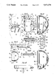
- FIG. 1 is a side view of the knee joint prosthesis of the present invention with the femur and tibia shown in phantom.
- FIG. 2 is a top plan view of the tibial prosthesis component of the present invention.
- FIG. 3 is a bottom plan view of the tibial prosthesis component of FIG. 2.
- FIG. 4 is a cross-section of the tibial prosthesis component taken along line 4--4 of FIG. 2.
- FIG. 5 is an enlarged fragmentary view taken along line 5--5 of FIG. 4.
- FIG. 6 is a broken side view of the tibial prosthesis component with a bearing insert shown in phantom.
- FIG. 7 is a top view of a bearing insert of the present invention.
- FIG. 8 is a section of the bearing insert taken along line 8--8 of FIG. 7.
- FIG. 9 is a bottom plan view of another embodiment of the tibial prosthesis component of the present invention.
- FIG. 10 is a side view of a further embodiment of the tibial prosthesis component of the present invention.
- FIG. 11 is a side view of the femoral prosthesis component of the present invention.
- FIG. 12 is a top view of the femoral prosthesis component of FIG. 11.
- FIG. 13 is an anterior view of the femoral prosthesis component of FIG. 11.
- FIG. 14 is an enlarged fragmentary view in section taken along line 14--14 of FIG. 11.
- the present invention relates to prostheses for implant in the body and is particularly described in connection with a prosthesis or implant for the knee joint.
- a preferred embodiment for a knee joint prosthesis implant according to the present invention is shown in FIG. 1 and includes a tibial prosthesis component 12, a femoral prosthesis component 14 and a bearing insert 60.
- the tibial component 12 is affixed to a suitably prepared site on the upper plateau 16 of the tibia 18, shown in phantom.
- the femoral component 14 is affixed to a suitably prepared site on a condyle 20 of a femur 22, shown in phantom.
- FIGS. 2-6 show a preferred embodiment of the tibial component 12 including a body 24 which, viewed from the top, has a generally asymmetrical, D-shaped configuration with an arcuate side wall 26 joined to a generally planar side wall 28 via curved side wall sections 29.
- the body 24 has a top or upper surface 30 connecting the upper edges of the planar side wall 28, the arcuate side wall 26 and the curved side wall sections 29.
- the body has a bottom or fixation surface 32 connecting the lower edges of the planar side wall 28, the arcuate side wall 26 and the curved side wall sections 29.
- a cavity 34 is formed in the top surface 30 of the body 24 defined by a planar cavity side wall 36 joined to an arcuate cavity side wall 38 by curved cavity wall end sections 40 and a cavity bottom wall 42 joining the lower edges of cavity side walls 36, 38 and 40.
- An inwardly tapered through hole 44 is formed in the cavity bottom wall 42 and extends substantially perpendicularly through the body 24.
- each curved cavity wall end section 40 has a lip 46 projecting from the curved cavity wall section into the interior of the cavity 34.
- the lip 46 has a chamfered surface 48 extending downwardly from the top surface 30 of the body at an angle of approximately 45°.
- the surface 48 terminates in a vertical cavity facing surface 50 which joins curved cavity wall section 40 via a horizontal surface 52.
- Curved cavity wall sections 40 extend downwardly from horizontal surface 52 to cavity bottom wall 42 at an angle of approximately 20° toward the interior of the cavity 34 such that lips 46 form grooves in the side wall curved end sections 40.
- the top surface 30 of the body 24 is generally flat except for a sloping surface 54 at an anterior portion extending from a straight edge 56 located on the top surface downwardly at an angle of approximately 30° with respect to the parallel top and bottom surfaces to meet the side walls of the body.
- a through hole 58 is formed in the anterior portion to extend through the body from sloping surface 54 to bottom surface 32 at an angle of approximately 60° with respect to the bottom surface 32 and perpendicular to surface 54.
- the body has an upper surface 68 joining the upper ends of the insert side walls 62, 64 and 66, while the lower ends of the side walls are joined by a lower surface 70.
- Upper surface 68 is slightly concave when viewed from the side, as shown in FIGS. 6 and 8.
- Each curved end section 66 is provided with a flexible protruding lip 72 extending upwardly and outwardly from the lower surface 70 toward the upper surface 68 at an angle of approximately 20° with respect to the end section 66, as best illustrated in FIG. 8, to terminate in an upper edge 73 spaced from the side wall curved end section 66.
- the insert 60 has a configuration mating with the configuration of cavity 34 and is received in the cavity 34, as shown in phantom in FIG.
- insert side walls 62, 64 and 66 in close abutment with the respective cavity side walls 36, 38 and 40 and the lips 72 engaged in the grooves beneath lips 46 to securely retain the insert in position within the cavity.
- a range of inserts ranging in thickness, for example, from approximately 8 mm to 15 mm as measured from the insert upper surface 68 to the insert lower surface 70, is provided so that the proper fit can be attained.
- the upper surface 68 of the insert will be elevated with respect to the top surface 30 of the tibial component body by varying amounts depending upon the thickness of the particular insert.
- the bearing insert is integrally fabricated in a unitary manner of ultrahigh molecular weight polyethylene.
- the fixation surface 32 of the body 24 has a recess 74 therein defined within the confines of the side walls 26, 28 and 29 of the body.
- a channel or portal 76 connects the recess 74 to the exterior of the body and extends from the recess 74 through the arcuate side wall 26 at the anterior portion of the body.
- the recess 74 and the channel 76 share a common end wall 78 which defines the depth to which the recess and channel extend above the bottom surface 32 into the interior of the body.
- a land 80 along the fixation surface 32 isolates the through hole 44 from the recess 74, while a land 82 along the fixation surface 32 isolates the through hole 58 from the recess 74.
- a rim 84 projects from the bottom surface 32 spaced from but following the curve of arcuate side wall 26 with an interruption at the location of channel 76. As is most clearly depicted in FIGS. 4 and 5, the rim 84 is triangular in cross-sectional configuration, with the apex of the triangle forming a sharp bottommost edge 86 for the body. The rim 84 defines a wall extending along the recess 74 and at least partially surrounding the recess.
- the tibial component 12 is provided in a range of sizes, for example, with the dimension A of the body ranging from approximately 37.5 mm to approximately 54 mm and the dimension B ranging from approximately 21 mm to approximately 33 mm, as shown in FIG. 2, to accommodate a range of sizes for optimal coverage of the tibial plateau.
- the asymmetrical "D" configuration of the body further contributes to optimal tibial plateau coverage in order to present a contact area for the femoral component coinciding with that of a normal knee.
- the tibial component 12 is particularly designed to be affixed to a suitably prepared tibial plateau through arthroscopic surgical techniques; however, the tibial component can be used in normal open surgery procedures for prosthetic knee replacement.
- the body can be grasped by an appropriate surgical instrument and placed in position on the tibial plateau with the bottommost edge 86 resting upon the tibial plateau.
- the body is affixed by a cancellous bone screw 88 inserted at an angle through hole 58 and into the anterior portion of the tibia as illustrated in FIG. 1.
- a second cancellous bone screw 90 can be inserted through the body into the tibia via through hole 44 if desired.
- the recess 74 formed in the bottom surface 32 of the body define, together with the tibial plateau, an enclosed cement receiving chamber which communicates with the exterior of the body through channel 76.
- a bone cement preferably low viscosity methyl-methacrylate, is injected into the chamber through channel 76 to form a physical bond between the body and the tibial plateau. It can be seen, therefore, that the tibial component can properly be positioned prior to the application of cement and need not be moved or disturbed in any manner thereby assuring precise and accurate positioning.
- the cement can be inserted in the cement receiving chamber by means of a needle or syringe to be compatible with arthroscopic techniques.
- the rim 84 forms a seal around the cement receiving chamber with respect to the tibial plateau to augment filling of the cement receiving chamber, and the rim 84 penetrates the tibial surface to establish a seal preventing escape of cement from the chamber while the bottom surface 32 engages the tibial plateau. Additionally, the rim 84 stabilizes the position of the tibial component on the tibial plateau.
- the lands 80 and 82 along the bottom surface 32 isolate the respective fixation screws from the cement so that the screws can be removed, if necessary.
- the bottom surface 32 and the wall 78 of recess 74 are textured to enhance the interface between the body and the cement.
- the invention contemplates a right medial/left lateral orientation for the tibial component in addition to the left medial/right lateral illustrated herein.
- a suitable bearing insert 60 can be inserted after the body has been implanted, or the insert 60 can be mounted in the body prior to implanting the body.
- FIG. 9 Another embodiment of a tibial component according to the present invention is shown in FIG. 9 wherein a body 88 is essentially the same as body 24 except that through hole 44 has been eliminated and the recess 90 follows the arcuate wall 26, as does end wall 92.
- the body 88 thus accommodates only a single screw which, due to its position at the anterior portion of the implant, provides sufficient fixation.
- FIG. 10 A further embodiment of the present invention is shown in FIG. 10 and is essentially the same as the tibial component of FIG. 9 except that a post 96 depends from the end wall 92 of the recess 90 at substantially the same position as through hole 44 shown in FIG. 3.
- the post 96 is intended to be inserted into a corresponding drilled hole in the tibial plateau.
- the post 96 is tapered to allow a press fit into the corresponding hole.
- the femoral component 14 of the prosthesis of the present invention is illustrated in FIGS. 11-15 and includes a body 100 having a curved configuration defining an arcuate outer bearing surface 102 with an anterior or distal end 104 and a posterior end 106.
- the bearing surface 102 is generally polycentric, that is, the surface lies on arcs of circles having more than one center and more than one radius to approximate the natural articulating surface of a femoral condyle.
- the posterior end 106 curves somewhat sharply while the anterior end 104 curves somewhat gradually. In other words, the radius cf an imaginary circle in which the anterior end 104 lies is greater than the radius of an imaginary circle in which the posterior end 106 lies.
- Body 100 further includes an inner fixation surface which joins the bearing surface 102 at side and end edges.
- the fixation surface includes a planar posterior section 118, a planar chamfer section 120 and a planar distal section 122.
- the posterior and distal sections 118 and 122 are oriented substantially perpendicular with respect to each other, while chamfer section 120 is oriented at an angle of substantially 45° with respect to the posterior and distal sections.
- the body 100 has a generally straight medial side edge 110 and a generally straight lateral side edge 112 parallel to edge 110 but about one half the length of the edge 110.
- the side edge 112 is joined to side edge 110 via a generally polycentric curved edge 114.
- An arcuate posterior edge 116 joins the opposite ends of the side edges 110 and 112.
- Side edge 110 extends along the sides of the posterior, chamfer and distal sections of the fixation surface.
- Side edge 112 extends along the sides of the posterior and chamfer sections and along a portion of the side of the distal section, the curved edge 114 extending along the remaining portion of the side of the distal section.
- a recess 124 is formed in the chamfer section 120 and the distal section 122 of the fixation surface.
- a side wall 126 of the recess 124 generally follows the side edges 110, 112 and 114 of the body 100, running generally parallel thereto but separated therefrom by a portion of the fixation surface.
- the recess is provided with a bottom surface 128 and terminates along a bottom edge 130 of the posterior section 118.
- a channel 132 is formed in the bottom surface 128 of the recess 124 extending generally parallel to the side edge 110 of the body 100 in the distal section 122 and through the curved side edge 114 of the body to establish communication with the exterior.
- Posts 136 and 138 project upwardly substantially perpendicular to bottom surface 128, preferably at an inclination of 5° from the plane of the posterior section 118.
- the posts 136 and 138 are generally cone-shaped and have respective tapered top ends 140 and 142. As depicted in FIG. 11, the post 136 is longer than the post 138, the post 138 being around two-thirds the length of post 136.
- a rim 144 projects from the fixation surface, spaced from but lying generally parallel to side edges 110, 112 and 114 of the body 100. As can be seen in FIG.
- the rim 144 also lies generally parallel to the side wall 126 of the recess 124 so as to at least partially surround the recess 124 along the chamfer section 120 and the distal section 122.
- the rim 144 is preferably triangular in cross-sectional configuration to provide a relatively sharp edge 148 as was discussed in connection with rim 84 for the tibial component 12 and as shown in FIG. 14.
- a semi-circular indentation 150 is provided on each side of the body 100 in distal section 122 proximate side edges 110 and 112 as shown in FIGS. 11, 12 and 13.
- the femoral component 14 is adapted to be positioned on a condylar surface of the femur after the surface has been suitably cut and shaped to conform to the fixation surface of the body 100.
- the femoral component may be positioned by means of open or arthroscopic surgical techniques with the indentations 150 engaged by a surgical tool for placement of the femoral component on the prepared femoral condyle.
- the posts 136 and 138 are fitted into drilled holes in the cut distal end of the femoral condyle, the tapered upper ends 140 and 142 of the posts allowing for a press fit.
- the rim 144 penetrates the bone to enhance securement and forms a seal with respect to the bone around the cement receiving chamber formed by the recess 124 and the surface of the bone.
- Cement is introduced into the chamber through the channel 132 by means of a syringe, a needle or the like as discussed in connection with the tibial component.
- the rim 144 inhibits rotation of the femoral component as do the posts 136 and 138.
- the fixation surface and the recess bottom surface 128 are textured to enhance the interface between the femoral component and the cement.
- the tibial and femoral components are preferably fabricated of metal, the preferred material for the tibial component being implant grade titanium, and for the femoral component cobalt-chromium.
- the surface 102 of the femoral component cooperates with the concave surface 68 of bearing insert 60 to allow the same freedom of movement afforded by a healthy knee.
- the nonmetallic insert 60 provides a bearing surface for the metallic femoral component similar to the cartilage in a natural knee joint.
- the plastic material from which the insert is fabricated provides a low coefficient of friction between the contacting surfaces and minimizes the rate of wear of the contacting surfaces of the components.
- the femoral component be available in a number of sizes, and in right medial/left lateral and left medial/right lateral versions to prevent interference with the patella.
- the knee joint prosthesis of the present invention can be used in conventional open, total knee replacement surgical procedures but is particularly useful for implant using arthroscopic surgical techniques due to the simplified cementing procedures and the stability permitted by the tibial and femoral prosthesis components coupled with the modular nature thereof and the use of bearing inserts of varying sizes to produce desired tibial thicknesses or heights.
- Method and apparatus for implant of the knee joint prosthesis of the present invention are disclosed in an application filed concurrently herewith by the same inventors, entitled “Methods and Apparatus for Arthroscopic Prosthetic Knee Replacement", the disclosure of which is incorporated herein by reference.
Abstract
Description
Claims (9)
Priority Applications (11)
| Application Number | Priority Date | Filing Date | Title |
|---|---|---|---|
| US07/462,528 US5171276A (en) | 1990-01-08 | 1990-01-08 | Knee joint prosthesis |
| AT91903749T ATE157859T1 (en) | 1990-01-08 | 1991-01-07 | PROSTHESIS |
| JP3503550A JPH05503644A (en) | 1990-01-08 | 1991-01-07 | knee joint prosthesis |
| PCT/US1991/000114 WO1991010412A1 (en) | 1990-01-08 | 1991-01-07 | Knee joint prosthesis |
| CA002073328A CA2073328C (en) | 1990-01-08 | 1991-01-07 | Knee joint prosthesis |
| EP91903749A EP0510103B1 (en) | 1990-01-08 | 1991-01-07 | Prosthesis |
| DE69127613T DE69127613T2 (en) | 1990-01-08 | 1991-01-07 | PROSTHESIS |
| AU72330/91A AU651085B2 (en) | 1990-01-08 | 1991-01-07 | Knee joint prosthesis |
| US07/773,268 US5201768A (en) | 1990-01-08 | 1991-10-09 | Prosthesis for implant on the tibial plateau of the knee |
| US07/773,408 US5207711A (en) | 1990-01-08 | 1991-10-09 | Knee joint prosthesis |
| US07/773,410 US5336266A (en) | 1990-01-08 | 1991-10-09 | Knee joint prosthesis |
Applications Claiming Priority (1)
| Application Number | Priority Date | Filing Date | Title |
|---|---|---|---|
| US07/462,528 US5171276A (en) | 1990-01-08 | 1990-01-08 | Knee joint prosthesis |
Related Child Applications (3)
| Application Number | Title | Priority Date | Filing Date |
|---|---|---|---|
| US07/773,410 Division US5336266A (en) | 1990-01-08 | 1991-10-09 | Knee joint prosthesis |
| US07/773,408 Division US5207711A (en) | 1990-01-08 | 1991-10-09 | Knee joint prosthesis |
| US07/773,268 Division US5201768A (en) | 1990-01-08 | 1991-10-09 | Prosthesis for implant on the tibial plateau of the knee |
Publications (1)
| Publication Number | Publication Date |
|---|---|
| US5171276A true US5171276A (en) | 1992-12-15 |
Family
ID=23836767
Family Applications (2)
| Application Number | Title | Priority Date | Filing Date |
|---|---|---|---|
| US07/462,528 Expired - Lifetime US5171276A (en) | 1990-01-08 | 1990-01-08 | Knee joint prosthesis |
| US07/773,410 Expired - Lifetime US5336266A (en) | 1990-01-08 | 1991-10-09 | Knee joint prosthesis |
Family Applications After (1)
| Application Number | Title | Priority Date | Filing Date |
|---|---|---|---|
| US07/773,410 Expired - Lifetime US5336266A (en) | 1990-01-08 | 1991-10-09 | Knee joint prosthesis |
Country Status (8)
| Country | Link |
|---|---|
| US (2) | US5171276A (en) |
| EP (1) | EP0510103B1 (en) |
| JP (1) | JPH05503644A (en) |
| AT (1) | ATE157859T1 (en) |
| AU (1) | AU651085B2 (en) |
| CA (1) | CA2073328C (en) |
| DE (1) | DE69127613T2 (en) |
| WO (1) | WO1991010412A1 (en) |
Cited By (114)
| Publication number | Priority date | Publication date | Assignee | Title |
|---|---|---|---|---|
| US5344460A (en) * | 1992-10-30 | 1994-09-06 | Encore Orthopedics, Inc. | Prosthesis system |
| US5441538A (en) * | 1993-04-12 | 1995-08-15 | Bonutti; Peter M. | Bone implant and method of securing |
| US5474559A (en) * | 1993-07-06 | 1995-12-12 | Zimmer, Inc. | Femoral milling instrumentation for use in total knee arthroplasty with optional cutting guide attachment |
| US5480444A (en) * | 1994-06-02 | 1996-01-02 | Incavo; Stephen J. | Hybrid tibial tray knee prosthesis |
| US5593411A (en) * | 1995-03-13 | 1997-01-14 | Zimmer, Inc. | Orthopaedic milling guide for milling intersecting planes |
| US5601563A (en) * | 1995-08-25 | 1997-02-11 | Zimmer, Inc. | Orthopaedic milling template with attachable cutting guide |
| US5609643A (en) * | 1995-03-13 | 1997-03-11 | Johnson & Johnson Professional, Inc. | Knee joint prosthesis |
| US5653714A (en) * | 1996-02-22 | 1997-08-05 | Zimmer, Inc. | Dual slide cutting guide |
| US5658293A (en) * | 1995-10-10 | 1997-08-19 | Zimmer, Inc. | Guide platform associated with intramedullary rod |
| US5743915A (en) * | 1993-07-06 | 1998-04-28 | Zimmer, Inc. | Femoral milling instrumentation for use in total knee arthoroplasty with optional cutting guide attachment |
| US5871546A (en) * | 1995-09-29 | 1999-02-16 | Johnson & Johnson Professional, Inc. | Femoral component condyle design for knee prosthesis |
| US5876460A (en) * | 1996-09-06 | 1999-03-02 | Bloebaum; Roy D. | Cemented prosthetic component and placement method |
| US6059831A (en) * | 1999-03-31 | 2000-05-09 | Biomet, Inc. | Method of implanting a uni-condylar knee prosthesis |
| WO2000030570A3 (en) * | 1998-11-23 | 2000-08-31 | Coripharm Medizinprodukte Gmbh | Partial endoprosthesis for knee joints and grinding tool for working a tibia |
| WO2000025700A3 (en) * | 1998-11-04 | 2000-09-08 | Blake A Stamper | Orthopedic prosthesis with cement compression ring |
| US6120546A (en) * | 1997-12-05 | 2000-09-19 | Sulzer Orthopedics Inc. | Implantable prosthesis having spring-engaged hole plugs |
| WO2002102254A2 (en) | 2001-06-14 | 2002-12-27 | Gerard Engh | Apparatus and method for sculpting the surface of a bone joint |
| US6503280B2 (en) | 2000-12-26 | 2003-01-07 | John A. Repicci | Prosthetic knee and method of inserting |
| FR2839442A1 (en) * | 2002-05-10 | 2003-11-14 | Dedienne Sante | Knee prosthesis comprises tibial base with wall in which there is long reinforcement and intermediate plate with comprising wall with projecting rib tightly engaged in reinforcement |
| US20060100714A1 (en) * | 2003-04-02 | 2006-05-11 | Ortho Development Corporation | Tibial augment connector |
| US20060235537A1 (en) * | 2005-04-18 | 2006-10-19 | Accin Corporation | Unicondylar knee implant |
| US20060259149A1 (en) * | 2005-03-07 | 2006-11-16 | David Barrett | Surgical assembly |
| US20070032876A1 (en) * | 2005-08-05 | 2007-02-08 | Ron Clark | Knee joint prosthesis |
| US7255712B1 (en) | 1997-04-15 | 2007-08-14 | Active Implants Corporation | Bone growth promoting implant |
| US20070299531A1 (en) * | 2006-06-22 | 2007-12-27 | Depuy Products, Inc. | Tibial insert and method for implanting the same |
| US20070299530A1 (en) * | 2006-06-22 | 2007-12-27 | Depuy Products, Inc. | Tibial insert having a reinforced keel |
| US20070299529A1 (en) * | 2006-06-22 | 2007-12-27 | Depuy Products, Inc. | Tibial insert having multiple keels |
| US20070299532A1 (en) * | 2006-06-22 | 2007-12-27 | Depuy Products, Inc. | Tibial insert having a keel including a bore formed therein |
| US7572295B2 (en) | 2001-12-04 | 2009-08-11 | Active Implants Corporation | Cushion bearing implants for load bearing applications |
| US20090228114A1 (en) * | 2008-02-29 | 2009-09-10 | Ron Clark | Femoral Prosthesis |
| US20090270995A1 (en) * | 2005-06-30 | 2009-10-29 | James Matthew Rhodes | Tibial insert and associated surgical method |
| US20090306670A1 (en) * | 2005-04-18 | 2009-12-10 | Uni-Knee, Llc | Unicondylar Knee Instrument System |
| US20100033560A1 (en) * | 2008-08-06 | 2010-02-11 | Hitachi High-Technologies Corporation | Method and Apparatus of Tilted Illumination Observation |
| US7695479B1 (en) | 2005-04-12 | 2010-04-13 | Biomet Manufacturing Corp. | Femoral sizer |
| US7695520B2 (en) | 2006-05-31 | 2010-04-13 | Biomet Manufacturing Corp. | Prosthesis and implementation system |
| US20100094429A1 (en) * | 2008-10-02 | 2010-04-15 | Mako Surgical Corp. | Prosthetic device for knee joint and methods of implanting and removing same |
| US7708741B1 (en) | 2001-08-28 | 2010-05-04 | Marctec, Llc | Method of preparing bones for knee replacement surgery |
| US7749229B1 (en) | 2000-01-14 | 2010-07-06 | Marctec, Llc | Total knee arthroplasty through shortened incision |
| US7758653B2 (en) | 2002-05-23 | 2010-07-20 | Active Implants Corporation | Implants |
| US7780672B2 (en) | 2006-02-27 | 2010-08-24 | Biomet Manufacturing Corp. | Femoral adjustment device and associated method |
| US7789885B2 (en) | 2003-01-15 | 2010-09-07 | Biomet Manufacturing Corp. | Instrumentation for knee resection |
| US7799084B2 (en) | 2002-10-23 | 2010-09-21 | Mako Surgical Corp. | Modular femoral component for a total knee joint replacement for minimally invasive implantation |
| US7803193B2 (en) | 1995-09-04 | 2010-09-28 | Active Implants Corporation | Knee prosthesis having a deformable articulation surface |
| US7837690B2 (en) | 2003-01-15 | 2010-11-23 | Biomet Manufacturing Corp. | Method and apparatus for less invasive knee resection |
| US7887542B2 (en) | 2003-01-15 | 2011-02-15 | Biomet Manufacturing Corp. | Method and apparatus for less invasive knee resection |
| US7959635B1 (en) | 2000-01-14 | 2011-06-14 | Marctec, Llc. | Limited incision total joint replacement methods |
| USD642263S1 (en) | 2007-10-25 | 2011-07-26 | Otismed Corporation | Arthroplasty jig blank |
| US8070752B2 (en) | 2006-02-27 | 2011-12-06 | Biomet Manufacturing Corp. | Patient specific alignment guide and inter-operative adjustment |
| US8123758B2 (en) | 2003-12-08 | 2012-02-28 | Biomet Manufacturing Corp. | Femoral guide for implanting a femoral knee prosthesis |
| US8160345B2 (en) | 2008-04-30 | 2012-04-17 | Otismed Corporation | System and method for image segmentation in generating computer models of a joint to undergo arthroplasty |
| US8157869B2 (en) | 2007-01-10 | 2012-04-17 | Biomet Manufacturing Corp. | Knee joint prosthesis system and method for implantation |
| US8157868B2 (en) | 2008-10-10 | 2012-04-17 | New York University | Implants for the treatment of osteoarthritis of the knee |
| US8163028B2 (en) | 2007-01-10 | 2012-04-24 | Biomet Manufacturing Corp. | Knee joint prosthesis system and method for implantation |
| US8187280B2 (en) | 2007-10-10 | 2012-05-29 | Biomet Manufacturing Corp. | Knee joint prosthesis system and method for implantation |
| US8221430B2 (en) | 2007-12-18 | 2012-07-17 | Otismed Corporation | System and method for manufacturing arthroplasty jigs |
| US20120209390A1 (en) * | 2009-02-10 | 2012-08-16 | Tornier Sas | Implant for bone and cartilage reconstruction |
| US8265949B2 (en) | 2007-09-27 | 2012-09-11 | Depuy Products, Inc. | Customized patient surgical plan |
| US8287601B2 (en) | 2010-09-30 | 2012-10-16 | Depuy Products, Inc. | Femoral component of a knee prosthesis having an angled cement pocket |
| US8311306B2 (en) | 2008-04-30 | 2012-11-13 | Otismed Corporation | System and method for image segmentation in generating computer models of a joint to undergo arthroplasty |
| US8317870B2 (en) | 2010-09-30 | 2012-11-27 | Depuy Products, Inc. | Tibial component of a knee prosthesis having an angled cement pocket |
| US8328873B2 (en) | 2007-01-10 | 2012-12-11 | Biomet Manufacturing Corp. | Knee joint prosthesis system and method for implantation |
| US8343159B2 (en) | 2007-09-30 | 2013-01-01 | Depuy Products, Inc. | Orthopaedic bone saw and method of use thereof |
| US8357111B2 (en) | 2007-09-30 | 2013-01-22 | Depuy Products, Inc. | Method and system for designing patient-specific orthopaedic surgical instruments |
| US8460303B2 (en) | 2007-10-25 | 2013-06-11 | Otismed Corporation | Arthroplasty systems and devices, and related methods |
| US8460302B2 (en) | 2006-12-18 | 2013-06-11 | Otismed Corporation | Arthroplasty devices and related methods |
| US8480679B2 (en) | 2008-04-29 | 2013-07-09 | Otismed Corporation | Generation of a computerized bone model representative of a pre-degenerated state and useable in the design and manufacture of arthroplasty devices |
| US8545509B2 (en) | 2007-12-18 | 2013-10-01 | Otismed Corporation | Arthroplasty system and related methods |
| US8551100B2 (en) | 2003-01-15 | 2013-10-08 | Biomet Manufacturing, Llc | Instrumentation for knee resection |
| US8562616B2 (en) | 2007-10-10 | 2013-10-22 | Biomet Manufacturing, Llc | Knee joint prosthesis system and method for implantation |
| US8617175B2 (en) | 2008-12-16 | 2013-12-31 | Otismed Corporation | Unicompartmental customized arthroplasty cutting jigs and methods of making the same |
| US8617171B2 (en) | 2007-12-18 | 2013-12-31 | Otismed Corporation | Preoperatively planning an arthroplasty procedure and generating a corresponding patient specific arthroplasty resection guide |
| US8715291B2 (en) | 2007-12-18 | 2014-05-06 | Otismed Corporation | Arthroplasty system and related methods |
| US8734455B2 (en) | 2008-02-29 | 2014-05-27 | Otismed Corporation | Hip resurfacing surgical guide tool |
| US8737700B2 (en) | 2007-12-18 | 2014-05-27 | Otismed Corporation | Preoperatively planning an arthroplasty procedure and generating a corresponding patient specific arthroplasty resection guide |
| US8747439B2 (en) | 2000-03-13 | 2014-06-10 | P Tech, Llc | Method of using ultrasonic vibration to secure body tissue with fastening element |
| US8777875B2 (en) | 2008-07-23 | 2014-07-15 | Otismed Corporation | System and method for manufacturing arthroplasty jigs having improved mating accuracy |
| US8801719B2 (en) | 2002-05-15 | 2014-08-12 | Otismed Corporation | Total joint arthroplasty system |
| US8808329B2 (en) | 1998-02-06 | 2014-08-19 | Bonutti Skeletal Innovations Llc | Apparatus and method for securing a portion of a body |
| US8814902B2 (en) | 2000-05-03 | 2014-08-26 | Bonutti Skeletal Innovations Llc | Method of securing body tissue |
| US20140277548A1 (en) * | 2013-03-15 | 2014-09-18 | Mako Surgical Corp. | Unicondylar tibial knee implant |
| US8845687B2 (en) | 1996-08-19 | 2014-09-30 | Bonutti Skeletal Innovations Llc | Anchor for securing a suture |
| US8845699B2 (en) | 1999-08-09 | 2014-09-30 | Bonutti Skeletal Innovations Llc | Method of securing tissue |
| WO2014159561A1 (en) * | 2013-03-14 | 2014-10-02 | Moximed, Inc. | Active and passive devices for redistributing forces for the medial and lateral knee |
| US20140343686A1 (en) * | 2011-12-07 | 2014-11-20 | Smith & Newphew, Inc. | Orthopedic augments having recessed pockets |
| US8940046B2 (en) | 2010-10-01 | 2015-01-27 | Maxx Orthopedics, Inc. | Method of implanting a prosthesis device using bone cement in liquid form |
| US9017336B2 (en) | 2006-02-15 | 2015-04-28 | Otismed Corporation | Arthroplasty devices and related methods |
| US9308094B2 (en) | 2012-05-14 | 2016-04-12 | Moximed, Inc. | Active and passive devices for redistributing forces for the medial and lateral knee |
| US9402637B2 (en) | 2012-10-11 | 2016-08-02 | Howmedica Osteonics Corporation | Customized arthroplasty cutting guides and surgical methods using the same |
| WO2016141141A1 (en) * | 2015-03-05 | 2016-09-09 | Trauner Kenneth B | Bone implant augment method and apparatus |
| US20170035583A1 (en) * | 2014-05-07 | 2017-02-09 | Otto Bock Healthcare Gmbh | Method for connecting at least two structural parts of an orthopedic component and orthopedic component having at least two structural parts |
| US9700329B2 (en) | 2006-02-27 | 2017-07-11 | Biomet Manufacturing, Llc | Patient-specific orthopedic instruments |
| US9743935B2 (en) | 2011-03-07 | 2017-08-29 | Biomet Manufacturing, Llc | Patient-specific femoral version guide |
| US9770238B2 (en) | 2001-12-03 | 2017-09-26 | P Tech, Llc | Magnetic positioning apparatus |
| US9795399B2 (en) | 2006-06-09 | 2017-10-24 | Biomet Manufacturing, Llc | Patient-specific knee alignment guide and associated method |
| US9808262B2 (en) | 2006-02-15 | 2017-11-07 | Howmedica Osteonics Corporation | Arthroplasty devices and related methods |
| US9913734B2 (en) | 2006-02-27 | 2018-03-13 | Biomet Manufacturing, Llc | Patient-specific acetabular alignment guides |
| US9968376B2 (en) | 2010-11-29 | 2018-05-15 | Biomet Manufacturing, Llc | Patient-specific orthopedic instruments |
| US10159498B2 (en) | 2008-04-16 | 2018-12-25 | Biomet Manufacturing, Llc | Method and apparatus for manufacturing an implant |
| US10206695B2 (en) | 2006-02-27 | 2019-02-19 | Biomet Manufacturing, Llc | Femoral acetabular impingement guide |
| US10278711B2 (en) | 2006-02-27 | 2019-05-07 | Biomet Manufacturing, Llc | Patient-specific femoral guide |
| US10390845B2 (en) | 2006-02-27 | 2019-08-27 | Biomet Manufacturing, Llc | Patient-specific shoulder guide |
| US10426492B2 (en) | 2006-02-27 | 2019-10-01 | Biomet Manufacturing, Llc | Patient specific alignment guide with cutting surface and laser indicator |
| US10441428B2 (en) | 2010-05-03 | 2019-10-15 | New York University | Early intervention knee implant device and methods |
| US10507029B2 (en) | 2006-02-27 | 2019-12-17 | Biomet Manufacturing, Llc | Patient-specific acetabular guides and associated instruments |
| US10582934B2 (en) | 2007-11-27 | 2020-03-10 | Howmedica Osteonics Corporation | Generating MRI images usable for the creation of 3D bone models employed to make customized arthroplasty jigs |
| US10603179B2 (en) | 2006-02-27 | 2020-03-31 | Biomet Manufacturing, Llc | Patient-specific augments |
| US10722310B2 (en) | 2017-03-13 | 2020-07-28 | Zimmer Biomet CMF and Thoracic, LLC | Virtual surgery planning system and method |
| US10743937B2 (en) | 2006-02-27 | 2020-08-18 | Biomet Manufacturing, Llc | Backup surgical instrument system and method |
| USD907207S1 (en) * | 2018-12-13 | 2021-01-05 | Christiaan Rudolf Oosthuizen | Tibial component |
| USD907208S1 (en) * | 2018-12-13 | 2021-01-05 | Christiaan Rudolf Oosthuizen | Fixed bearing insert |
| US11051829B2 (en) | 2018-06-26 | 2021-07-06 | DePuy Synthes Products, Inc. | Customized patient-specific orthopaedic surgical instrument |
| US11534313B2 (en) | 2006-02-27 | 2022-12-27 | Biomet Manufacturing, Llc | Patient-specific pre-operative planning |
| US11554019B2 (en) | 2007-04-17 | 2023-01-17 | Biomet Manufacturing, Llc | Method and apparatus for manufacturing an implant |
| US11950786B2 (en) | 2021-07-02 | 2024-04-09 | DePuy Synthes Products, Inc. | Customized patient-specific orthopaedic surgical instrument |
Families Citing this family (68)
| Publication number | Priority date | Publication date | Assignee | Title |
|---|---|---|---|---|
| EP0611559A1 (en) * | 1993-02-18 | 1994-08-24 | Societe Civile Essor | Unicondylar knee prostheses |
| DE19647155C2 (en) * | 1996-11-14 | 1998-11-19 | Plus Endoprothetik Ag | Implant |
| US8480754B2 (en) | 2001-05-25 | 2013-07-09 | Conformis, Inc. | Patient-adapted and improved articular implants, designs and related guide tools |
| US5941911A (en) * | 1997-01-16 | 1999-08-24 | Buechel; Frederick F. | Orthopedic prosthesis employing bone screws and cement |
| GB9713186D0 (en) * | 1997-06-24 | 1997-08-27 | Univ Sheffield | Artificial joints |
| US5879407A (en) * | 1997-07-17 | 1999-03-09 | Waggener; Herbert A. | Wear resistant ball and socket joint |
| DE69839308T2 (en) * | 1998-07-27 | 2009-04-16 | Amedica Corp., Salt Lake City | CEMENTED PROSTHETIC COMPONENT |
| US6132468A (en) * | 1998-09-10 | 2000-10-17 | Mansmann; Kevin A. | Arthroscopic replacement of cartilage using flexible inflatable envelopes |
| US20050209703A1 (en) * | 1999-04-02 | 2005-09-22 | Fell Barry M | Surgically implantable prosthetic system |
| US7491235B2 (en) * | 1999-05-10 | 2009-02-17 | Fell Barry M | Surgically implantable knee prosthesis |
| US20050033424A1 (en) * | 1999-05-10 | 2005-02-10 | Fell Barry M. | Surgically implantable knee prosthesis |
| US7297161B2 (en) * | 1999-05-10 | 2007-11-20 | Fell Barry M | Surgically implantable knee prosthesis |
| US7338524B2 (en) * | 1999-05-10 | 2008-03-04 | Fell Barry M | Surgically implantable knee prosthesis |
| US6299645B1 (en) * | 1999-07-23 | 2001-10-09 | William S. Ogden | Dove tail total knee replacement unicompartmental |
| US6554866B1 (en) * | 1999-10-29 | 2003-04-29 | Sulzer Orthopedics Ltd. | Mono-condylar knee joint prosthesis |
| US8114163B2 (en) | 2000-04-10 | 2012-02-14 | Biomet Manufacturing Corp. | Method and apparatus for adjusting height and angle for a radial head |
| US8920509B2 (en) | 2000-04-10 | 2014-12-30 | Biomet Manufacturing, Llc | Modular radial head prosthesis |
| US8535382B2 (en) | 2000-04-10 | 2013-09-17 | Biomet Manufacturing, Llc | Modular radial head prostheses |
| US6520964B2 (en) | 2000-05-01 | 2003-02-18 | Std Manufacturing, Inc. | System and method for joint resurface repair |
| US6610067B2 (en) | 2000-05-01 | 2003-08-26 | Arthrosurface, Incorporated | System and method for joint resurface repair |
| US6569202B2 (en) * | 2001-04-02 | 2003-05-27 | Whiteside Biomechanics, Inc. | Tray and liner for joint replacement system |
| US6482209B1 (en) * | 2001-06-14 | 2002-11-19 | Gerard A. Engh | Apparatus and method for sculpting the surface of a joint |
| US6797006B2 (en) * | 2002-06-18 | 2004-09-28 | Zimmer Technology, Inc. | Porous unicondylar knee |
| US7033397B2 (en) * | 2003-02-03 | 2006-04-25 | Zimmer Technology, Inc. | Mobile bearing unicondylar tibial knee prosthesis |
| US6916341B2 (en) * | 2003-02-20 | 2005-07-12 | Lindsey R. Rolston | Device and method for bicompartmental arthroplasty |
| US8388624B2 (en) | 2003-02-24 | 2013-03-05 | Arthrosurface Incorporated | Trochlear resurfacing system and method |
| FR2856916B1 (en) * | 2003-07-04 | 2006-01-06 | Biomet Merck France | UNICOMPARTIMENTAL KNEE PROSTHESIS |
| AR043908A1 (en) * | 2004-02-27 | 2005-08-17 | Morhac Martin Jorge Dr | MEDIAL OR SIDE FEMORAL COMPONENT AND MEDIAL-SIDE UNICOMPARTIMENTAL PROTECTION OF KNEE |
| US20090270994A1 (en) * | 2004-02-27 | 2009-10-29 | Roberto Schaefer | Medial and lateral femoral implants for single-compartment knee prosthesis |
| EP1574185B1 (en) * | 2004-03-09 | 2012-05-23 | Zimmer Technology, Inc. | Tibial knee component with a mobile bearing |
| CA2572584A1 (en) | 2004-06-28 | 2006-01-12 | Arthrosurface, Inc. | System for articular surface replacement |
| US8852195B2 (en) | 2004-07-09 | 2014-10-07 | Zimmer, Inc. | Guide templates for surgical implants and related methods |
| FR2885031B1 (en) * | 2005-05-02 | 2007-07-13 | Patrick Hechard | PROSTHETIC PIECE COMPRISING A PROSTHESIS FOR REPLACING AN ARTICULATION BETWEEN TWO BONDS OF A HUMAN BEING OR THE LIKE |
| AU2006297137A1 (en) * | 2005-09-30 | 2007-04-12 | Conformis Inc. | Joint arthroplasty devices |
| CN101534750B (en) * | 2006-09-06 | 2015-12-16 | 史密夫和内修有限公司 | With implant and the relevant method of transitional surface |
| AU2007332787A1 (en) | 2006-12-11 | 2008-06-19 | Arthrosurface Incorporated | Retrograde resection apparatus and method |
| US7582118B2 (en) * | 2007-02-06 | 2009-09-01 | Zimmer Technology, Inc. | Femoral trochlea prostheses |
| US8128704B2 (en) * | 2007-02-06 | 2012-03-06 | Zimmer, Inc. | Femoral trochlea prostheses |
| US8328874B2 (en) | 2007-03-30 | 2012-12-11 | Depuy Products, Inc. | Mobile bearing assembly |
| US8142510B2 (en) | 2007-03-30 | 2012-03-27 | Depuy Products, Inc. | Mobile bearing assembly having a non-planar interface |
| US8764841B2 (en) | 2007-03-30 | 2014-07-01 | DePuy Synthes Products, LLC | Mobile bearing assembly having a closed track |
| US8147558B2 (en) | 2007-03-30 | 2012-04-03 | Depuy Products, Inc. | Mobile bearing assembly having multiple articulation interfaces |
| US8147557B2 (en) | 2007-03-30 | 2012-04-03 | Depuy Products, Inc. | Mobile bearing insert having offset dwell point |
| US7896924B1 (en) | 2008-01-09 | 2011-03-01 | Howmedica Osteonics Corp. | Unicondylar femoral prosthetic implant component |
| US8430930B2 (en) | 2008-12-18 | 2013-04-30 | 4-Web, Inc. | Truss implant |
| WO2010099231A2 (en) | 2009-02-24 | 2010-09-02 | Conformis, Inc. | Automated systems for manufacturing patient-specific orthopedic implants and instrumentation |
| US10945743B2 (en) | 2009-04-17 | 2021-03-16 | Arthrosurface Incorporated | Glenoid repair system and methods of use thereof |
| WO2010121250A1 (en) | 2009-04-17 | 2010-10-21 | Arthrosurface Incorporated | Glenoid resurfacing system and method |
| CA2759027C (en) | 2009-04-17 | 2020-02-25 | Arthrosurface Incorporated | Glenoid resurfacing system and method |
| AU2010327987B2 (en) | 2009-12-11 | 2015-04-02 | Conformis, Inc. | Patient-specific and patient-engineered orthopedic implants |
| AU2011222404A1 (en) | 2010-03-05 | 2012-09-27 | Arthrosurface Incorporated | Tibial resurfacing system and method |
| WO2012021764A2 (en) | 2010-08-13 | 2012-02-16 | Smith & Nephew, Inc. | Orthopaedic implants and methods |
| GB2483492A (en) | 2010-09-10 | 2012-03-14 | John Goodfellow | Femoral prosthetic component with extension |
| CN103476363B (en) | 2011-02-15 | 2017-06-30 | 康复米斯公司 | Operation and the instrument of change and/or asymmetry are dissected in improved suitable patient's type joint implant and treatment, assessment, correction, modification and/or adaptation |
| US9066716B2 (en) | 2011-03-30 | 2015-06-30 | Arthrosurface Incorporated | Suture coil and suture sheath for tissue repair |
| US20130030529A1 (en) * | 2011-07-29 | 2013-01-31 | Jessee Hunt | Implant interface system and method |
| BR112014002240B1 (en) * | 2011-09-19 | 2021-05-11 | Tecres S.P.A | Temporary modular spacer device for human body joints |
| WO2013096399A1 (en) * | 2011-12-19 | 2013-06-27 | Smith & Nephew, Inc. | Orthopedic insert systems and methods |
| WO2013096746A1 (en) | 2011-12-22 | 2013-06-27 | Arthrosurface Incorporated | System and method for bone fixation |
| US9468448B2 (en) | 2012-07-03 | 2016-10-18 | Arthrosurface Incorporated | System and method for joint resurfacing and repair |
| CN104780870B (en) | 2012-09-25 | 2018-03-02 | 4网络公司 | Programmable implant and the method for repairing bone structure using programmable implant |
| EP2967873A4 (en) | 2013-03-15 | 2017-03-01 | 4-web, Inc. | Traumatic bone fracture repair systems and methods |
| US9492200B2 (en) | 2013-04-16 | 2016-11-15 | Arthrosurface Incorporated | Suture system and method |
| US11607319B2 (en) | 2014-03-07 | 2023-03-21 | Arthrosurface Incorporated | System and method for repairing articular surfaces |
| US10624748B2 (en) | 2014-03-07 | 2020-04-21 | Arthrosurface Incorporated | System and method for repairing articular surfaces |
| US20150250472A1 (en) | 2014-03-07 | 2015-09-10 | Arthrosurface Incorporated | Delivery System for Articular Surface Implant |
| US11160663B2 (en) | 2017-08-04 | 2021-11-02 | Arthrosurface Incorporated | Multicomponent articular surface implant |
| WO2020186099A1 (en) | 2019-03-12 | 2020-09-17 | Arthrosurface Incorporated | Humeral and glenoid articular surface implant systems and methods |
Citations (40)
| Publication number | Priority date | Publication date | Assignee | Title |
|---|---|---|---|---|
| FR1046920A (en) * | 1951-11-15 | 1953-12-09 | Support device during limb amputations | |
| US3852830A (en) * | 1973-02-15 | 1974-12-10 | Richards Mfg Co | Knee prosthesis |
| US3953899A (en) * | 1973-05-17 | 1976-05-04 | Chas. F. Thackray Limited | Knee arthroplasty |
| US3958278A (en) * | 1974-04-22 | 1976-05-25 | National Research Development Corporation | Endoprosthetic knee joint |
| US4000525A (en) * | 1975-08-21 | 1977-01-04 | The United States Of America As Represented By The Secretary Of The Navy | Ceramic prosthetic implant suitable for a knee joint plateau |
| US4034418A (en) * | 1975-05-26 | 1977-07-12 | The Governing Council Of The University Of Toronto | Artificial knee joint |
| US4055862A (en) * | 1976-01-23 | 1977-11-01 | Zimmer Usa, Inc. | Human body implant of graphitic carbon fiber reinforced ultra-high molecular weight polyethylene |
| US4085466A (en) * | 1974-11-18 | 1978-04-25 | National Research Development Corporation | Prosthetic joint device |
| SU719625A1 (en) * | 1978-04-26 | 1980-03-05 | Центральный Ордена Трудового Красного Знамени Научно-Исследовательский Институт Травматологии И Ортопедии Им. Н.Н.Приорова | Artificial knee joint |
| US4193140A (en) * | 1975-12-19 | 1980-03-18 | Richards Manufacturing Company, Inc. | Knee prosthesis |
| US4207627A (en) * | 1979-01-18 | 1980-06-17 | Cloutier Jean Marie | Knee prosthesis |
| US4211228A (en) * | 1979-01-24 | 1980-07-08 | Cloutier Jean Marie | Multipurpose tibial template |
| US4219893A (en) * | 1977-09-01 | 1980-09-02 | United States Surgical Corporation | Prosthetic knee joint |
| US4274163A (en) * | 1979-07-16 | 1981-06-23 | The Regents Of The University Of California | Prosthetic fixation technique |
| US4309778A (en) * | 1979-07-02 | 1982-01-12 | Biomedical Engineering Corp. | New Jersey meniscal bearing knee replacement |
| US4340978A (en) * | 1979-07-02 | 1982-07-27 | Biomedical Engineering Corp. | New Jersey meniscal bearing knee replacement |
| US4355429A (en) * | 1979-01-26 | 1982-10-26 | Osteo Ag | Slide prosthesis for the knee joint |
| US4470158A (en) * | 1978-03-10 | 1984-09-11 | Biomedical Engineering Corp. | Joint endoprosthesis |
| US4531243A (en) * | 1982-10-05 | 1985-07-30 | Sulzer Brothers Limited | Artificial hip joint socket |
| US4563778A (en) * | 1983-02-23 | 1986-01-14 | Minnesota Mining And Manufacturing Company | Prosthetic acetabular cup |
| US4593685A (en) * | 1983-10-17 | 1986-06-10 | Pfizer Hospital Products Group Inc. | Bone cement applicator |
| US4653489A (en) * | 1984-04-02 | 1987-03-31 | Tronzo Raymond G | Fenestrated hip screw and method of augmented fixation |
| US4711639A (en) * | 1984-09-11 | 1987-12-08 | S+G Implants Gmbh | Anchorage for tibia plates |
| US4714474A (en) * | 1986-05-12 | 1987-12-22 | Dow Corning Wright Corporation | Tibial knee joint prosthesis with removable articulating surface insert |
| US4728332A (en) * | 1984-11-28 | 1988-03-01 | Albrektsson Bjoern | Artificial menisco-tibial joint |
| US4743261A (en) * | 1986-01-27 | 1988-05-10 | Epinette Jean Alain | Tibial component for unicompartmental knee prosthesis for a cementness implantation |
| US4769040A (en) * | 1986-11-18 | 1988-09-06 | Queen's University At Kingston | Tibial prosthesis |
| SU1424829A1 (en) * | 1987-01-30 | 1988-09-23 | Ш.Б.-Ахмедов, П.И Чобану, А.И. Крецу и Н.Ш Ахмедов | Endoprosthesis for hip joint |
| US4795468A (en) * | 1987-12-23 | 1989-01-03 | Zimmer, Inc. | Mechanism and method for locking a bearing insert to the base of a prosthetic implant |
| US4838891A (en) * | 1984-11-28 | 1989-06-13 | Branemark Per Ingvar | Joint prothesis |
| EP0320138A1 (en) * | 1987-11-30 | 1989-06-14 | Philip Christopher Noble | Sealing device for introducing cement into a bone canal |
| US4865607A (en) * | 1985-10-02 | 1989-09-12 | Ulrich Witzel | Tibial plate for a knee-joint endoprosthesis |
| US4888024A (en) * | 1985-11-08 | 1989-12-19 | Powlan Roy Y | Prosthetic device and method of fixation within the medullary cavity of bones |
| US4892550A (en) * | 1985-12-30 | 1990-01-09 | Huebsch Donald L | Endoprosthesis device and method |
| US4892547A (en) * | 1988-02-03 | 1990-01-09 | Biomet, Inc. | Partially stabilized knee prosthesis |
| DE3937786A1 (en) * | 1989-11-14 | 1990-07-26 | Jansson Volkmar Dipl Ing Dr Me | Internal prosthesis for hip joint - contains passage for cement insertion between it and bone |
| US4963152A (en) * | 1986-10-27 | 1990-10-16 | Intermedics Orthopedics, Inc. | Asymmetric prosthetic tibial component |
| US4979957A (en) * | 1989-09-11 | 1990-12-25 | Zimmer, Inc. | Textured prosthetic implant |
| US4997448A (en) * | 1989-02-13 | 1991-03-05 | Feiler Frederic C | Proximal cement sealing plug for hip prosthesis |
| US5041141A (en) * | 1987-11-03 | 1991-08-20 | Orthopaedic Technology B.V. | Method of shaping an endo-prosthesis, a femoral head prosthesis, an acetabulum prosthesis and a method of fixing a femoral head prosthesis in a bone |
Family Cites Families (3)
| Publication number | Priority date | Publication date | Assignee | Title |
|---|---|---|---|---|
| GB1485771A (en) * | 1973-09-07 | 1977-09-14 | Nat Res Dev | Prosthetic bone joint devices |
| US4166292A (en) * | 1977-09-08 | 1979-09-04 | Carbomedics, Inc. | Stress reinforced artificial joint prostheses |
| US4714473A (en) * | 1985-07-25 | 1987-12-22 | Harrington Arthritis Research Center | Knee prosthesis |
-
1990
- 1990-01-08 US US07/462,528 patent/US5171276A/en not_active Expired - Lifetime
-
1991
- 1991-01-07 JP JP3503550A patent/JPH05503644A/en active Pending
- 1991-01-07 CA CA002073328A patent/CA2073328C/en not_active Expired - Lifetime
- 1991-01-07 AT AT91903749T patent/ATE157859T1/en not_active IP Right Cessation
- 1991-01-07 DE DE69127613T patent/DE69127613T2/en not_active Expired - Fee Related
- 1991-01-07 EP EP91903749A patent/EP0510103B1/en not_active Expired - Lifetime
- 1991-01-07 AU AU72330/91A patent/AU651085B2/en not_active Ceased
- 1991-01-07 WO PCT/US1991/000114 patent/WO1991010412A1/en active IP Right Grant
- 1991-10-09 US US07/773,410 patent/US5336266A/en not_active Expired - Lifetime
Patent Citations (40)
| Publication number | Priority date | Publication date | Assignee | Title |
|---|---|---|---|---|
| FR1046920A (en) * | 1951-11-15 | 1953-12-09 | Support device during limb amputations | |
| US3852830A (en) * | 1973-02-15 | 1974-12-10 | Richards Mfg Co | Knee prosthesis |
| US3953899A (en) * | 1973-05-17 | 1976-05-04 | Chas. F. Thackray Limited | Knee arthroplasty |
| US3958278A (en) * | 1974-04-22 | 1976-05-25 | National Research Development Corporation | Endoprosthetic knee joint |
| US4085466A (en) * | 1974-11-18 | 1978-04-25 | National Research Development Corporation | Prosthetic joint device |
| US4034418A (en) * | 1975-05-26 | 1977-07-12 | The Governing Council Of The University Of Toronto | Artificial knee joint |
| US4000525A (en) * | 1975-08-21 | 1977-01-04 | The United States Of America As Represented By The Secretary Of The Navy | Ceramic prosthetic implant suitable for a knee joint plateau |
| US4193140A (en) * | 1975-12-19 | 1980-03-18 | Richards Manufacturing Company, Inc. | Knee prosthesis |
| US4055862A (en) * | 1976-01-23 | 1977-11-01 | Zimmer Usa, Inc. | Human body implant of graphitic carbon fiber reinforced ultra-high molecular weight polyethylene |
| US4219893A (en) * | 1977-09-01 | 1980-09-02 | United States Surgical Corporation | Prosthetic knee joint |
| US4470158A (en) * | 1978-03-10 | 1984-09-11 | Biomedical Engineering Corp. | Joint endoprosthesis |
| SU719625A1 (en) * | 1978-04-26 | 1980-03-05 | Центральный Ордена Трудового Красного Знамени Научно-Исследовательский Институт Травматологии И Ортопедии Им. Н.Н.Приорова | Artificial knee joint |
| US4207627A (en) * | 1979-01-18 | 1980-06-17 | Cloutier Jean Marie | Knee prosthesis |
| US4211228A (en) * | 1979-01-24 | 1980-07-08 | Cloutier Jean Marie | Multipurpose tibial template |
| US4355429A (en) * | 1979-01-26 | 1982-10-26 | Osteo Ag | Slide prosthesis for the knee joint |
| US4309778A (en) * | 1979-07-02 | 1982-01-12 | Biomedical Engineering Corp. | New Jersey meniscal bearing knee replacement |
| US4340978A (en) * | 1979-07-02 | 1982-07-27 | Biomedical Engineering Corp. | New Jersey meniscal bearing knee replacement |
| US4274163A (en) * | 1979-07-16 | 1981-06-23 | The Regents Of The University Of California | Prosthetic fixation technique |
| US4531243A (en) * | 1982-10-05 | 1985-07-30 | Sulzer Brothers Limited | Artificial hip joint socket |
| US4563778A (en) * | 1983-02-23 | 1986-01-14 | Minnesota Mining And Manufacturing Company | Prosthetic acetabular cup |
| US4593685A (en) * | 1983-10-17 | 1986-06-10 | Pfizer Hospital Products Group Inc. | Bone cement applicator |
| US4653489A (en) * | 1984-04-02 | 1987-03-31 | Tronzo Raymond G | Fenestrated hip screw and method of augmented fixation |
| US4711639A (en) * | 1984-09-11 | 1987-12-08 | S+G Implants Gmbh | Anchorage for tibia plates |
| US4838891A (en) * | 1984-11-28 | 1989-06-13 | Branemark Per Ingvar | Joint prothesis |
| US4728332A (en) * | 1984-11-28 | 1988-03-01 | Albrektsson Bjoern | Artificial menisco-tibial joint |
| US4865607A (en) * | 1985-10-02 | 1989-09-12 | Ulrich Witzel | Tibial plate for a knee-joint endoprosthesis |
| US4888024A (en) * | 1985-11-08 | 1989-12-19 | Powlan Roy Y | Prosthetic device and method of fixation within the medullary cavity of bones |
| US4892550A (en) * | 1985-12-30 | 1990-01-09 | Huebsch Donald L | Endoprosthesis device and method |
| US4743261A (en) * | 1986-01-27 | 1988-05-10 | Epinette Jean Alain | Tibial component for unicompartmental knee prosthesis for a cementness implantation |
| US4714474A (en) * | 1986-05-12 | 1987-12-22 | Dow Corning Wright Corporation | Tibial knee joint prosthesis with removable articulating surface insert |
| US4963152A (en) * | 1986-10-27 | 1990-10-16 | Intermedics Orthopedics, Inc. | Asymmetric prosthetic tibial component |
| US4769040A (en) * | 1986-11-18 | 1988-09-06 | Queen's University At Kingston | Tibial prosthesis |
| SU1424829A1 (en) * | 1987-01-30 | 1988-09-23 | Ш.Б.-Ахмедов, П.И Чобану, А.И. Крецу и Н.Ш Ахмедов | Endoprosthesis for hip joint |
| US5041141A (en) * | 1987-11-03 | 1991-08-20 | Orthopaedic Technology B.V. | Method of shaping an endo-prosthesis, a femoral head prosthesis, an acetabulum prosthesis and a method of fixing a femoral head prosthesis in a bone |
| EP0320138A1 (en) * | 1987-11-30 | 1989-06-14 | Philip Christopher Noble | Sealing device for introducing cement into a bone canal |
| US4795468A (en) * | 1987-12-23 | 1989-01-03 | Zimmer, Inc. | Mechanism and method for locking a bearing insert to the base of a prosthetic implant |
| US4892547A (en) * | 1988-02-03 | 1990-01-09 | Biomet, Inc. | Partially stabilized knee prosthesis |
| US4997448A (en) * | 1989-02-13 | 1991-03-05 | Feiler Frederic C | Proximal cement sealing plug for hip prosthesis |
| US4979957A (en) * | 1989-09-11 | 1990-12-25 | Zimmer, Inc. | Textured prosthetic implant |
| DE3937786A1 (en) * | 1989-11-14 | 1990-07-26 | Jansson Volkmar Dipl Ing Dr Me | Internal prosthesis for hip joint - contains passage for cement insertion between it and bone |
Cited By (208)
| Publication number | Priority date | Publication date | Assignee | Title |
|---|---|---|---|---|
| US5344460A (en) * | 1992-10-30 | 1994-09-06 | Encore Orthopedics, Inc. | Prosthesis system |
| US5441538A (en) * | 1993-04-12 | 1995-08-15 | Bonutti; Peter M. | Bone implant and method of securing |
| US6217617B1 (en) * | 1993-04-12 | 2001-04-17 | Peter M. Bonutti | Bone implant and method of securing |
| US5624462A (en) * | 1993-04-12 | 1997-04-29 | Bonutti; Peter M. | Bone implant and method of securing |
| US5474559A (en) * | 1993-07-06 | 1995-12-12 | Zimmer, Inc. | Femoral milling instrumentation for use in total knee arthroplasty with optional cutting guide attachment |
| US5860981A (en) * | 1993-07-06 | 1999-01-19 | Dennis W. Burke | Guide for femoral milling instrumention for use in total knee arthroplasty |
| US5769855A (en) * | 1993-07-06 | 1998-06-23 | Zimmer Inc. | Femoral milling instrumentation for use in total knee arthroplasty with optional cutting guide attachment |
| US5743915A (en) * | 1993-07-06 | 1998-04-28 | Zimmer, Inc. | Femoral milling instrumentation for use in total knee arthoroplasty with optional cutting guide attachment |
| US5683471A (en) * | 1994-06-02 | 1997-11-04 | Incavo; Stephen J. | Hybrid tibial tray knee prosthesis |
| US5480444A (en) * | 1994-06-02 | 1996-01-02 | Incavo; Stephen J. | Hybrid tibial tray knee prosthesis |
| US5593411A (en) * | 1995-03-13 | 1997-01-14 | Zimmer, Inc. | Orthopaedic milling guide for milling intersecting planes |
| US5609643A (en) * | 1995-03-13 | 1997-03-11 | Johnson & Johnson Professional, Inc. | Knee joint prosthesis |
| US5601563A (en) * | 1995-08-25 | 1997-02-11 | Zimmer, Inc. | Orthopaedic milling template with attachable cutting guide |
| US7803193B2 (en) | 1995-09-04 | 2010-09-28 | Active Implants Corporation | Knee prosthesis having a deformable articulation surface |
| US5871546A (en) * | 1995-09-29 | 1999-02-16 | Johnson & Johnson Professional, Inc. | Femoral component condyle design for knee prosthesis |
| US5658293A (en) * | 1995-10-10 | 1997-08-19 | Zimmer, Inc. | Guide platform associated with intramedullary rod |
| US5653714A (en) * | 1996-02-22 | 1997-08-05 | Zimmer, Inc. | Dual slide cutting guide |
| US8845687B2 (en) | 1996-08-19 | 2014-09-30 | Bonutti Skeletal Innovations Llc | Anchor for securing a suture |
| US6355067B1 (en) | 1996-09-06 | 2002-03-12 | Aaron. A. Hofmann | Cemented prosthetic component and placement method |
| US5876460A (en) * | 1996-09-06 | 1999-03-02 | Bloebaum; Roy D. | Cemented prosthetic component and placement method |
| US7255712B1 (en) | 1997-04-15 | 2007-08-14 | Active Implants Corporation | Bone growth promoting implant |
| US6120546A (en) * | 1997-12-05 | 2000-09-19 | Sulzer Orthopedics Inc. | Implantable prosthesis having spring-engaged hole plugs |
| US8808329B2 (en) | 1998-02-06 | 2014-08-19 | Bonutti Skeletal Innovations Llc | Apparatus and method for securing a portion of a body |
| US6179876B1 (en) | 1998-11-04 | 2001-01-30 | Blake A. Stamper | Orthopedic prosthesis with cement compression ring and method |
| WO2000025700A3 (en) * | 1998-11-04 | 2000-09-08 | Blake A Stamper | Orthopedic prosthesis with cement compression ring |
| WO2000030570A3 (en) * | 1998-11-23 | 2000-08-31 | Coripharm Medizinprodukte Gmbh | Partial endoprosthesis for knee joints and grinding tool for working a tibia |
| US6059831A (en) * | 1999-03-31 | 2000-05-09 | Biomet, Inc. | Method of implanting a uni-condylar knee prosthesis |
| US8845699B2 (en) | 1999-08-09 | 2014-09-30 | Bonutti Skeletal Innovations Llc | Method of securing tissue |
| US7828852B2 (en) | 2000-01-14 | 2010-11-09 | Marctec, Llc. | Inlaid articular implant |
| US7931690B1 (en) | 2000-01-14 | 2011-04-26 | Marctec, Llc | Method of resurfacing an articular surface of a bone |
| US7749229B1 (en) | 2000-01-14 | 2010-07-06 | Marctec, Llc | Total knee arthroplasty through shortened incision |
| US8425522B2 (en) | 2000-01-14 | 2013-04-23 | Bonutti Skeletal Innovations Llc | Joint replacement method |
| US9192459B2 (en) | 2000-01-14 | 2015-11-24 | Bonutti Skeletal Innovations Llc | Method of performing total knee arthroplasty |
| US8632552B2 (en) | 2000-01-14 | 2014-01-21 | Bonutti Skeletal Innovations Llc | Method of preparing a femur and tibia in knee arthroplasty |
| US8133229B1 (en) * | 2000-01-14 | 2012-03-13 | Marctec, Llc. | Knee arthroplasty method |
| US9101443B2 (en) | 2000-01-14 | 2015-08-11 | Bonutti Skeletal Innovations Llc | Methods for robotic arthroplasty |
| US7959635B1 (en) | 2000-01-14 | 2011-06-14 | Marctec, Llc. | Limited incision total joint replacement methods |
| US8784495B2 (en) | 2000-01-14 | 2014-07-22 | Bonutti Skeletal Innovations Llc | Segmental knee arthroplasty |
| US9795394B2 (en) | 2000-01-14 | 2017-10-24 | Bonutti Skeletal Innovations Llc | Method for placing implant using robotic system |
| US7837736B2 (en) | 2000-01-14 | 2010-11-23 | Marctec, Llc | Minimally invasive surgical systems and methods |
| US7806896B1 (en) | 2000-01-14 | 2010-10-05 | Marctec, Llc | Knee arthroplasty method |
| US7806897B1 (en) | 2000-01-14 | 2010-10-05 | Marctec, Llc | Knee arthroplasty and preservation of the quadriceps mechanism |
| US8747439B2 (en) | 2000-03-13 | 2014-06-10 | P Tech, Llc | Method of using ultrasonic vibration to secure body tissue with fastening element |
| US8814902B2 (en) | 2000-05-03 | 2014-08-26 | Bonutti Skeletal Innovations Llc | Method of securing body tissue |
| US6503280B2 (en) | 2000-12-26 | 2003-01-07 | John A. Repicci | Prosthetic knee and method of inserting |
| US6726724B2 (en) | 2000-12-26 | 2004-04-27 | John A. Repicci | Prosthetic knee |
| WO2002102254A2 (en) | 2001-06-14 | 2002-12-27 | Gerard Engh | Apparatus and method for sculpting the surface of a bone joint |
| US7708741B1 (en) | 2001-08-28 | 2010-05-04 | Marctec, Llc | Method of preparing bones for knee replacement surgery |
| US10321918B2 (en) | 2001-08-28 | 2019-06-18 | Bonutti Skeletal Innovations Llc | Methods for robotic surgery using a cannula |
| US10231739B1 (en) | 2001-08-28 | 2019-03-19 | Bonutti Skeletal Innovations Llc | System and method for robotic surgery |
| US8834490B2 (en) | 2001-08-28 | 2014-09-16 | Bonutti Skeletal Innovations Llc | Method for robotic arthroplasty using navigation |
| US8840629B2 (en) | 2001-08-28 | 2014-09-23 | Bonutti Skeletal Innovations Llc | Robotic arthroplasty system including navigation |
| US8858557B2 (en) | 2001-08-28 | 2014-10-14 | Bonutti Skeletal Innovations Llc | Method of preparing a femur and tibia in knee arthroplasty |
| US9763683B2 (en) | 2001-08-28 | 2017-09-19 | Bonutti Skeletal Innovations Llc | Method for performing surgical procedures using optical cutting guides |
| US8641726B2 (en) | 2001-08-28 | 2014-02-04 | Bonutti Skeletal Innovations Llc | Method for robotic arthroplasty using navigation |
| US9060797B2 (en) | 2001-08-28 | 2015-06-23 | Bonutti Skeletal Innovations Llc | Method of preparing a femur and tibia in knee arthroplasty |
| US8623030B2 (en) | 2001-08-28 | 2014-01-07 | Bonutti Skeletal Innovations Llc | Robotic arthroplasty system including navigation |
| US10470780B2 (en) | 2001-08-28 | 2019-11-12 | Bonutti Skeletal Innovations Llc | Systems and methods for ligament balancing in robotic surgery |
| US9770238B2 (en) | 2001-12-03 | 2017-09-26 | P Tech, Llc | Magnetic positioning apparatus |
| US8814946B2 (en) | 2001-12-04 | 2014-08-26 | Active Implants Corporation | Cushion bearing implants for load bearing applications |
| EP2145604A1 (en) | 2001-12-04 | 2010-01-20 | Active Implants Corporation | Cushion bearing implants for load bearing applications |
| US7572295B2 (en) | 2001-12-04 | 2009-08-11 | Active Implants Corporation | Cushion bearing implants for load bearing applications |
| FR2839442A1 (en) * | 2002-05-10 | 2003-11-14 | Dedienne Sante | Knee prosthesis comprises tibial base with wall in which there is long reinforcement and intermediate plate with comprising wall with projecting rib tightly engaged in reinforcement |
| US8801719B2 (en) | 2002-05-15 | 2014-08-12 | Otismed Corporation | Total joint arthroplasty system |
| US8801720B2 (en) | 2002-05-15 | 2014-08-12 | Otismed Corporation | Total joint arthroplasty system |
| US7758653B2 (en) | 2002-05-23 | 2010-07-20 | Active Implants Corporation | Implants |
| US7799084B2 (en) | 2002-10-23 | 2010-09-21 | Mako Surgical Corp. | Modular femoral component for a total knee joint replacement for minimally invasive implantation |
| US8551100B2 (en) | 2003-01-15 | 2013-10-08 | Biomet Manufacturing, Llc | Instrumentation for knee resection |
| US9023053B2 (en) | 2003-01-15 | 2015-05-05 | Biomet Manufacturing, Llc | Instrumentation for knee resection |
| US9693788B2 (en) | 2003-01-15 | 2017-07-04 | Biomet Manufacturing, Llc | Instrumentation for knee resection |
| US8870883B2 (en) | 2003-01-15 | 2014-10-28 | Biomet Manufacturing, Llc | Method for less invasive knee resection |
| US7887542B2 (en) | 2003-01-15 | 2011-02-15 | Biomet Manufacturing Corp. | Method and apparatus for less invasive knee resection |
| US7837690B2 (en) | 2003-01-15 | 2010-11-23 | Biomet Manufacturing Corp. | Method and apparatus for less invasive knee resection |
| US7789885B2 (en) | 2003-01-15 | 2010-09-07 | Biomet Manufacturing Corp. | Instrumentation for knee resection |
| US8518047B2 (en) | 2003-01-15 | 2013-08-27 | Biomet Manufacturing, Llc | Method and apparatus for less invasive knee resection |
| US8016891B2 (en) | 2003-04-02 | 2011-09-13 | Ortho Development Corporation | Tibial augment connector |
| US20060100714A1 (en) * | 2003-04-02 | 2006-05-11 | Ortho Development Corporation | Tibial augment connector |
| US8123758B2 (en) | 2003-12-08 | 2012-02-28 | Biomet Manufacturing Corp. | Femoral guide for implanting a femoral knee prosthesis |
| US8834486B2 (en) | 2003-12-08 | 2014-09-16 | Biomet Manufacturing, Llc | Femoral guide for implanting a femoral knee prosthesis |
| US20060259149A1 (en) * | 2005-03-07 | 2006-11-16 | David Barrett | Surgical assembly |
| US8034058B2 (en) * | 2005-03-17 | 2011-10-11 | Depuy International Limited | Tibial cement skirt assembly |
| US7695479B1 (en) | 2005-04-12 | 2010-04-13 | Biomet Manufacturing Corp. | Femoral sizer |
| US8057478B2 (en) | 2005-04-18 | 2011-11-15 | Arthrex, Inc. | Unicondylar knee instrument system |
| US20060235537A1 (en) * | 2005-04-18 | 2006-10-19 | Accin Corporation | Unicondylar knee implant |
| US7578850B2 (en) | 2005-04-18 | 2009-08-25 | Uni-Knee, Llc | Unicondylar knee implant |
| US20090306670A1 (en) * | 2005-04-18 | 2009-12-10 | Uni-Knee, Llc | Unicondylar Knee Instrument System |
| US8709091B2 (en) * | 2005-06-30 | 2014-04-29 | DePuy Synthes Products, LLC | Tibial insert and associated surgical method |
| US20090270995A1 (en) * | 2005-06-30 | 2009-10-29 | James Matthew Rhodes | Tibial insert and associated surgical method |
| US20070032876A1 (en) * | 2005-08-05 | 2007-02-08 | Ron Clark | Knee joint prosthesis |
| US7862619B2 (en) | 2005-08-05 | 2011-01-04 | Vot, Llc | Knee joint prosthesis |
| US9017336B2 (en) | 2006-02-15 | 2015-04-28 | Otismed Corporation | Arthroplasty devices and related methods |
| US9808262B2 (en) | 2006-02-15 | 2017-11-07 | Howmedica Osteonics Corporation | Arthroplasty devices and related methods |
| US9700329B2 (en) | 2006-02-27 | 2017-07-11 | Biomet Manufacturing, Llc | Patient-specific orthopedic instruments |
| US10278711B2 (en) | 2006-02-27 | 2019-05-07 | Biomet Manufacturing, Llc | Patient-specific femoral guide |
| US8070752B2 (en) | 2006-02-27 | 2011-12-06 | Biomet Manufacturing Corp. | Patient specific alignment guide and inter-operative adjustment |
| US7780672B2 (en) | 2006-02-27 | 2010-08-24 | Biomet Manufacturing Corp. | Femoral adjustment device and associated method |
| US10603179B2 (en) | 2006-02-27 | 2020-03-31 | Biomet Manufacturing, Llc | Patient-specific augments |
| US10390845B2 (en) | 2006-02-27 | 2019-08-27 | Biomet Manufacturing, Llc | Patient-specific shoulder guide |
| US10743937B2 (en) | 2006-02-27 | 2020-08-18 | Biomet Manufacturing, Llc | Backup surgical instrument system and method |
| US9913734B2 (en) | 2006-02-27 | 2018-03-13 | Biomet Manufacturing, Llc | Patient-specific acetabular alignment guides |
| US10426492B2 (en) | 2006-02-27 | 2019-10-01 | Biomet Manufacturing, Llc | Patient specific alignment guide with cutting surface and laser indicator |
| US10206695B2 (en) | 2006-02-27 | 2019-02-19 | Biomet Manufacturing, Llc | Femoral acetabular impingement guide |
| US11534313B2 (en) | 2006-02-27 | 2022-12-27 | Biomet Manufacturing, Llc | Patient-specific pre-operative planning |
| US10507029B2 (en) | 2006-02-27 | 2019-12-17 | Biomet Manufacturing, Llc | Patient-specific acetabular guides and associated instruments |
| US7695520B2 (en) | 2006-05-31 | 2010-04-13 | Biomet Manufacturing Corp. | Prosthesis and implementation system |
| US9795399B2 (en) | 2006-06-09 | 2017-10-24 | Biomet Manufacturing, Llc | Patient-specific knee alignment guide and associated method |
| US11576689B2 (en) | 2006-06-09 | 2023-02-14 | Biomet Manufacturing, Llc | Patient-specific knee alignment guide and associated method |
| US10893879B2 (en) | 2006-06-09 | 2021-01-19 | Biomet Manufacturing, Llc | Patient-specific knee alignment guide and associated method |
| US10206697B2 (en) | 2006-06-09 | 2019-02-19 | Biomet Manufacturing, Llc | Patient-specific knee alignment guide and associated method |
| US8764839B2 (en) | 2006-06-22 | 2014-07-01 | DePuy Synthes Products, LLC | Tibial insert having a keel including a bore formed therein |
| US20070299532A1 (en) * | 2006-06-22 | 2007-12-27 | Depuy Products, Inc. | Tibial insert having a keel including a bore formed therein |
| US8114165B2 (en) | 2006-06-22 | 2012-02-14 | Depuy Products, Inc. | Tibial insert and method for implanting the same |
| US20070299531A1 (en) * | 2006-06-22 | 2007-12-27 | Depuy Products, Inc. | Tibial insert and method for implanting the same |
| US20070299530A1 (en) * | 2006-06-22 | 2007-12-27 | Depuy Products, Inc. | Tibial insert having a reinforced keel |
| US20070299529A1 (en) * | 2006-06-22 | 2007-12-27 | Depuy Products, Inc. | Tibial insert having multiple keels |
| US8163027B2 (en) | 2006-06-22 | 2012-04-24 | Depuy Products, Inc. | Tibial insert having a reinforced keel |
| US8540778B2 (en) | 2006-06-22 | 2013-09-24 | DePuy Synthes Products, LLC | Tibial insert having multiple keels |
| US8460302B2 (en) | 2006-12-18 | 2013-06-11 | Otismed Corporation | Arthroplasty devices and related methods |
| US8480751B2 (en) | 2007-01-10 | 2013-07-09 | Biomet Manufacturing, Llc | Knee joint prosthesis system and method for implantation |
| US8157869B2 (en) | 2007-01-10 | 2012-04-17 | Biomet Manufacturing Corp. | Knee joint prosthesis system and method for implantation |
| US8936648B2 (en) | 2007-01-10 | 2015-01-20 | Biomet Manufacturing, Llc | Knee joint prosthesis system and method for implantation |
| US8328873B2 (en) | 2007-01-10 | 2012-12-11 | Biomet Manufacturing Corp. | Knee joint prosthesis system and method for implantation |
| US8163028B2 (en) | 2007-01-10 | 2012-04-24 | Biomet Manufacturing Corp. | Knee joint prosthesis system and method for implantation |
| US11554019B2 (en) | 2007-04-17 | 2023-01-17 | Biomet Manufacturing, Llc | Method and apparatus for manufacturing an implant |
| US8265949B2 (en) | 2007-09-27 | 2012-09-11 | Depuy Products, Inc. | Customized patient surgical plan |
| US11931049B2 (en) | 2007-09-30 | 2024-03-19 | DePuy Synthes Products, Inc. | Apparatus and method for fabricating a customized patient-specific orthopaedic instrument |
| US10828046B2 (en) | 2007-09-30 | 2020-11-10 | DePuy Synthes Products, Inc. | Apparatus and method for fabricating a customized patient-specific orthopaedic instrument |
| US8343159B2 (en) | 2007-09-30 | 2013-01-01 | Depuy Products, Inc. | Orthopaedic bone saw and method of use thereof |
| US10028750B2 (en) | 2007-09-30 | 2018-07-24 | DePuy Synthes Products, Inc. | Apparatus and method for fabricating a customized patient-specific orthopaedic instrument |
| US11696768B2 (en) | 2007-09-30 | 2023-07-11 | DePuy Synthes Products, Inc. | Apparatus and method for fabricating a customized patient-specific orthopaedic instrument |
| US8357111B2 (en) | 2007-09-30 | 2013-01-22 | Depuy Products, Inc. | Method and system for designing patient-specific orthopaedic surgical instruments |
| US8377068B2 (en) | 2007-09-30 | 2013-02-19 | DePuy Synthes Products, LLC. | Customized patient-specific instrumentation for use in orthopaedic surgical procedures |
| US8357166B2 (en) | 2007-09-30 | 2013-01-22 | Depuy Products, Inc. | Customized patient-specific instrumentation and method for performing a bone re-cut |
| US8398645B2 (en) | 2007-09-30 | 2013-03-19 | DePuy Synthes Products, LLC | Femoral tibial customized patient-specific orthopaedic surgical instrumentation |
| US8361076B2 (en) | 2007-09-30 | 2013-01-29 | Depuy Products, Inc. | Patient-customizable device and system for performing an orthopaedic surgical procedure |
| US9763793B2 (en) | 2007-10-10 | 2017-09-19 | Biomet Manufacturing, Llc | Knee joint prosthesis system and method for implantation |
| US8562616B2 (en) | 2007-10-10 | 2013-10-22 | Biomet Manufacturing, Llc | Knee joint prosthesis system and method for implantation |
| US10736747B2 (en) | 2007-10-10 | 2020-08-11 | Biomet Manufacturing, Llc | Knee joint prosthesis system and method for implantation |
| US8187280B2 (en) | 2007-10-10 | 2012-05-29 | Biomet Manufacturing Corp. | Knee joint prosthesis system and method for implantation |
| USD642263S1 (en) | 2007-10-25 | 2011-07-26 | Otismed Corporation | Arthroplasty jig blank |
| USD691719S1 (en) | 2007-10-25 | 2013-10-15 | Otismed Corporation | Arthroplasty jig blank |
| US8460303B2 (en) | 2007-10-25 | 2013-06-11 | Otismed Corporation | Arthroplasty systems and devices, and related methods |
| US10582934B2 (en) | 2007-11-27 | 2020-03-10 | Howmedica Osteonics Corporation | Generating MRI images usable for the creation of 3D bone models employed to make customized arthroplasty jigs |
| US8737700B2 (en) | 2007-12-18 | 2014-05-27 | Otismed Corporation | Preoperatively planning an arthroplasty procedure and generating a corresponding patient specific arthroplasty resection guide |
| US8617171B2 (en) | 2007-12-18 | 2013-12-31 | Otismed Corporation | Preoperatively planning an arthroplasty procedure and generating a corresponding patient specific arthroplasty resection guide |
| US9649170B2 (en) | 2007-12-18 | 2017-05-16 | Howmedica Osteonics Corporation | Arthroplasty system and related methods |
| US8545509B2 (en) | 2007-12-18 | 2013-10-01 | Otismed Corporation | Arthroplasty system and related methods |
| US8221430B2 (en) | 2007-12-18 | 2012-07-17 | Otismed Corporation | System and method for manufacturing arthroplasty jigs |
| US8968320B2 (en) | 2007-12-18 | 2015-03-03 | Otismed Corporation | System and method for manufacturing arthroplasty jigs |
| US8715291B2 (en) | 2007-12-18 | 2014-05-06 | Otismed Corporation | Arthroplasty system and related methods |
| US8100981B2 (en) | 2008-02-29 | 2012-01-24 | Vot, Llc | Tibial prosthesis |
| US9408618B2 (en) | 2008-02-29 | 2016-08-09 | Howmedica Osteonics Corporation | Total hip replacement surgical guide tool |
| US20090228114A1 (en) * | 2008-02-29 | 2009-09-10 | Ron Clark | Femoral Prosthesis |
| US8226727B2 (en) * | 2008-02-29 | 2012-07-24 | Vot, Llc | Femoral prosthesis |
| US20090228112A1 (en) * | 2008-02-29 | 2009-09-10 | Ron Clark | Tibial Prosthesis |
| US8734455B2 (en) | 2008-02-29 | 2014-05-27 | Otismed Corporation | Hip resurfacing surgical guide tool |
| US10159498B2 (en) | 2008-04-16 | 2018-12-25 | Biomet Manufacturing, Llc | Method and apparatus for manufacturing an implant |
| US9646113B2 (en) | 2008-04-29 | 2017-05-09 | Howmedica Osteonics Corporation | Generation of a computerized bone model representative of a pre-degenerated state and useable in the design and manufacture of arthroplasty devices |
| US8480679B2 (en) | 2008-04-29 | 2013-07-09 | Otismed Corporation | Generation of a computerized bone model representative of a pre-degenerated state and useable in the design and manufacture of arthroplasty devices |
| US8311306B2 (en) | 2008-04-30 | 2012-11-13 | Otismed Corporation | System and method for image segmentation in generating computer models of a joint to undergo arthroplasty |
| US9208263B2 (en) | 2008-04-30 | 2015-12-08 | Howmedica Osteonics Corporation | System and method for image segmentation in generating computer models of a joint to undergo arthroplasty |
| US8483469B2 (en) | 2008-04-30 | 2013-07-09 | Otismed Corporation | System and method for image segmentation in generating computer models of a joint to undergo arthroplasty |
| US8532361B2 (en) | 2008-04-30 | 2013-09-10 | Otismed Corporation | System and method for image segmentation in generating computer models of a joint to undergo arthroplasty |
| US8160345B2 (en) | 2008-04-30 | 2012-04-17 | Otismed Corporation | System and method for image segmentation in generating computer models of a joint to undergo arthroplasty |
| US8777875B2 (en) | 2008-07-23 | 2014-07-15 | Otismed Corporation | System and method for manufacturing arthroplasty jigs having improved mating accuracy |
| US20100033560A1 (en) * | 2008-08-06 | 2010-02-11 | Hitachi High-Technologies Corporation | Method and Apparatus of Tilted Illumination Observation |
| US20100094429A1 (en) * | 2008-10-02 | 2010-04-15 | Mako Surgical Corp. | Prosthetic device for knee joint and methods of implanting and removing same |
| US9717598B2 (en) * | 2008-10-02 | 2017-08-01 | Mako Surgical Corp. | Prosthetic device for knee joint and methods of implanting and removing same |
| AU2009298425B2 (en) * | 2008-10-02 | 2015-05-14 | Mako Surgical Corp. | Prosthetic device for knee joint and methods of implanting and removing same |
| US8157868B2 (en) | 2008-10-10 | 2012-04-17 | New York University | Implants for the treatment of osteoarthritis of the knee |
| US8603179B2 (en) | 2008-10-10 | 2013-12-10 | New York University | Implants for the treatment of osteoarthritis of the knee |
| US9125747B2 (en) | 2008-10-10 | 2015-09-08 | New York University | Implants for the treatment of osteoarthritis of the knee |
| US8617175B2 (en) | 2008-12-16 | 2013-12-31 | Otismed Corporation | Unicompartmental customized arthroplasty cutting jigs and methods of making the same |
| US20120209390A1 (en) * | 2009-02-10 | 2012-08-16 | Tornier Sas | Implant for bone and cartilage reconstruction |
| US10105229B2 (en) * | 2009-02-10 | 2018-10-23 | Tornier | Methods for bone and cartilage reconstruction |
| US11197762B2 (en) | 2009-02-10 | 2021-12-14 | Tornier Sas | Implant for bone and cartilage reconstruction |
| US11324522B2 (en) | 2009-10-01 | 2022-05-10 | Biomet Manufacturing, Llc | Patient specific alignment guide with cutting surface and laser indicator |
| US10893876B2 (en) | 2010-03-05 | 2021-01-19 | Biomet Manufacturing, Llc | Method and apparatus for manufacturing an implant |
| US10441428B2 (en) | 2010-05-03 | 2019-10-15 | New York University | Early intervention knee implant device and methods |
| US9724202B2 (en) | 2010-09-30 | 2017-08-08 | Depuy Ireland Unlimited Company | Femoral component of a knee prosthesis having an angled cement pocket |
| US8845746B2 (en) | 2010-09-30 | 2014-09-30 | Depuy (Ireland) | Femoral component of a knee prosthesis having an angled posterior cement pocket |
| US8317870B2 (en) | 2010-09-30 | 2012-11-27 | Depuy Products, Inc. | Tibial component of a knee prosthesis having an angled cement pocket |
| US8287601B2 (en) | 2010-09-30 | 2012-10-16 | Depuy Products, Inc. | Femoral component of a knee prosthesis having an angled cement pocket |
| US8940046B2 (en) | 2010-10-01 | 2015-01-27 | Maxx Orthopedics, Inc. | Method of implanting a prosthesis device using bone cement in liquid form |
| US11234719B2 (en) | 2010-11-03 | 2022-02-01 | Biomet Manufacturing, Llc | Patient-specific shoulder guide |
| US9968376B2 (en) | 2010-11-29 | 2018-05-15 | Biomet Manufacturing, Llc | Patient-specific orthopedic instruments |
| US9743935B2 (en) | 2011-03-07 | 2017-08-29 | Biomet Manufacturing, Llc | Patient-specific femoral version guide |
| US20180064541A1 (en) * | 2011-12-07 | 2018-03-08 | Smith & Nephew, Inc. | Orthopedic augments having recessed pockets |
| US9814582B2 (en) * | 2011-12-07 | 2017-11-14 | Smith & Nephew, Inc. | Orthopedic augments having recessed pockets |
| US20140343686A1 (en) * | 2011-12-07 | 2014-11-20 | Smith & Newphew, Inc. | Orthopedic augments having recessed pockets |
| US11135067B2 (en) | 2011-12-07 | 2021-10-05 | Smith & Nephew, Inc. | Orthopedic augments having recessed pockets |
| US10045848B2 (en) | 2012-05-14 | 2018-08-14 | Moximed, Inc. | Active and passive devices for redistributing forces for the medial and lateral knee |
| US9308094B2 (en) | 2012-05-14 | 2016-04-12 | Moximed, Inc. | Active and passive devices for redistributing forces for the medial and lateral knee |
| US9402637B2 (en) | 2012-10-11 | 2016-08-02 | Howmedica Osteonics Corporation | Customized arthroplasty cutting guides and surgical methods using the same |
| WO2014159561A1 (en) * | 2013-03-14 | 2014-10-02 | Moximed, Inc. | Active and passive devices for redistributing forces for the medial and lateral knee |
| US20140277548A1 (en) * | 2013-03-15 | 2014-09-18 | Mako Surgical Corp. | Unicondylar tibial knee implant |
| US9445909B2 (en) * | 2013-03-15 | 2016-09-20 | Mako Surgical Corp. | Unicondylar tibial knee implant |
| US20140343681A1 (en) * | 2013-03-15 | 2014-11-20 | Mako Surgical Corp. | Unicondylar tibial knee implant |
| US9907658B2 (en) | 2013-03-15 | 2018-03-06 | Mako Surgical Corp. | Unicondylar tibial knee implant |
| US9744044B2 (en) * | 2013-03-15 | 2017-08-29 | Mako Surgical Corp. | Unicondylar tibial knee implant |
| US20170035583A1 (en) * | 2014-05-07 | 2017-02-09 | Otto Bock Healthcare Gmbh | Method for connecting at least two structural parts of an orthopedic component and orthopedic component having at least two structural parts |
| US11590005B2 (en) | 2014-05-07 | 2023-02-28 | Ottobock Se & Co. Kgaa | Method for connecting at least two structural parts of an orthopedic component and orthopedic component having at least two structural parts |
| WO2016141141A1 (en) * | 2015-03-05 | 2016-09-09 | Trauner Kenneth B | Bone implant augment method and apparatus |
| US10722310B2 (en) | 2017-03-13 | 2020-07-28 | Zimmer Biomet CMF and Thoracic, LLC | Virtual surgery planning system and method |
| US11051829B2 (en) | 2018-06-26 | 2021-07-06 | DePuy Synthes Products, Inc. | Customized patient-specific orthopaedic surgical instrument |
| USD907207S1 (en) * | 2018-12-13 | 2021-01-05 | Christiaan Rudolf Oosthuizen | Tibial component |
| USD907208S1 (en) * | 2018-12-13 | 2021-01-05 | Christiaan Rudolf Oosthuizen | Fixed bearing insert |
| US11950786B2 (en) | 2021-07-02 | 2024-04-09 | DePuy Synthes Products, Inc. | Customized patient-specific orthopaedic surgical instrument |
Also Published As
| Publication number | Publication date |
|---|---|
| DE69127613T2 (en) | 1998-03-26 |
| AU7233091A (en) | 1991-08-05 |
| CA2073328C (en) | 2000-06-13 |
| AU651085B2 (en) | 1994-07-14 |
| JPH05503644A (en) | 1993-06-17 |
| US5336266A (en) | 1994-08-09 |
| WO1991010412A1 (en) | 1991-07-25 |
| EP0510103B1 (en) | 1997-09-10 |
| EP0510103A1 (en) | 1992-10-28 |
| ATE157859T1 (en) | 1997-09-15 |
| EP0510103A4 (en) | 1993-07-28 |
| CA2073328A1 (en) | 1991-07-09 |
| DE69127613D1 (en) | 1997-10-16 |
Similar Documents
| Publication | Publication Date | Title |
|---|---|---|
| US5171276A (en) | Knee joint prosthesis | |
| US5207711A (en) | Knee joint prosthesis | |
| US5201768A (en) | Prosthesis for implant on the tibial plateau of the knee | |
| US8226727B2 (en) | Femoral prosthesis | |
| US6139581A (en) | Posterior compensation tibial tray | |
| US4808185A (en) | Tibial prosthesis, template and reamer | |
| US3987500A (en) | Surgically implantable total ankle prosthesis | |
| US8709091B2 (en) | Tibial insert and associated surgical method | |
| EP0183669B1 (en) | Joint prosthesis | |
| US5383937A (en) | Recessed patellar prosthesis | |
| US4205400A (en) | Metallo-polymeric prosthesis with cavitied interconnection | |
| CA1298039C (en) | Prosthesis for tibial component of knee joint | |
| US7862619B2 (en) | Knee joint prosthesis | |
| US20050154470A1 (en) | Modular phrosthesis assembly including tapered adjustments | |
| EP3400911B1 (en) | Tibial tray with fixation features | |
| EP1154741B1 (en) | Orthopedic prosthesis with cement compression ring | |
| CA2628841A1 (en) | Mounting system and method for enhancing implant fixation to bone | |
| US20210338448A1 (en) | Talar Ankle Implant | |
| US20220202580A1 (en) | Cementless Screw-In-Peg Fixation |
Legal Events
| Date | Code | Title | Description |
|---|---|---|---|
| AS | Assignment |
Owner name: CONCEPT, INC., A CORP. OF FL, FLORIDA Free format text: ASSIGNMENT OF ASSIGNORS INTEREST.;ASSIGNORS:CASPARI, RICHARD B.;ROBERTS, JEFFREY G.;TREACE, JAMES T.;REEL/FRAME:005478/0679;SIGNING DATES FROM 19900302 TO 19900404 |
|
| AS | Assignment |
Owner name: LINVATEC CORPORATION Free format text: 12-26-1990 FL;ASSIGNOR:CONCEPT, INC.;REEL/FRAME:005803/0257 Effective date: 19901220 |
|
| STCF | Information on status: patent grant |
Free format text: PATENTED CASE |
|
| FPAY | Fee payment |
Year of fee payment: 4 |
|
| AS | Assignment |
Owner name: ZIMMER, INC., INDIANA Free format text: ASSIGNMENT OF ASSIGNORS INTEREST;ASSIGNORS:CASPARI, RICHARD B.;CASPARI ENTERPRISES, INC.;REEL/FRAME:009798/0284 Effective date: 19990211 |
|
| AS | Assignment |
Owner name: BRISTOL-MYERS SQIBB COMPANY, NEW YORK Free format text: ASSIGNMENT OF ASSIGNORS INTEREST;ASSIGNOR:ZIMMER, INC.;REEL/FRAME:009833/0170 Effective date: 19990316 |
|
| FPAY | Fee payment |
Year of fee payment: 8 |
|
| AS | Assignment |
Owner name: ZIMMER, INC., INDIANA Free format text: ASSIGNMENT OF ASSIGNORS INTEREST;ASSIGNOR:BRISTOL-MYERS SQUIBB COMPANY;REEL/FRAME:012729/0494 Effective date: 20020114 |
|
| AS | Assignment |
Owner name: ZIMMER TECHNOLOGY, INC., ILLINOIS Free format text: ASSIGNMENT OF ASSIGNORS INTEREST;ASSIGNOR:ZIMMER, INC.;REEL/FRAME:013862/0766 Effective date: 20020628 |
|
| FEPP | Fee payment procedure |
Free format text: PAYOR NUMBER ASSIGNED (ORIGINAL EVENT CODE: ASPN); ENTITY STATUS OF PATENT OWNER: LARGE ENTITY |
|
| FPAY | Fee payment |
Year of fee payment: 12 |