US5170176A - Quadrifilar helix antenna - Google Patents
Quadrifilar helix antenna Download PDFInfo
- Publication number
- US5170176A US5170176A US07/659,657 US65965791A US5170176A US 5170176 A US5170176 A US 5170176A US 65965791 A US65965791 A US 65965791A US 5170176 A US5170176 A US 5170176A
- Authority
- US
- United States
- Prior art keywords
- helix
- conductors
- linear
- linear conductors
- axis
- Prior art date
- Legal status (The legal status is an assumption and is not a legal conclusion. Google has not performed a legal analysis and makes no representation as to the accuracy of the status listed.)
- Expired - Lifetime
Links
Images


Classifications
-
- H—ELECTRICITY
- H01—ELECTRIC ELEMENTS
- H01Q—ANTENNAS, i.e. RADIO AERIALS
- H01Q11/00—Electrically-long antennas having dimensions more than twice the shortest operating wavelength and consisting of conductive active radiating elements
- H01Q11/02—Non-resonant antennas, e.g. travelling-wave antenna
- H01Q11/08—Helical antennas
Definitions
- the present invention relates to a small mobile antenna in a mobile satellite communication system.
- the mobile satellite communication system can provide a high quality communication service in a wide area.
- a communication service for ships is now available all over the world by using the INMALSAT system.
- Mobile communication systems for aircraft, and/or land mobile stations have also now been developed.
- a small antenna which has half sphere coverage does not need to track a desired satellite, and is considered promising for making an antenna small.
- a circularly polarized radio wave is used for a mobile satellite communication system, and a mobile antenna with a wide angle, and excellent axis-ratio characteristics has been required.
- a quadrifilar helix antenna which has four coils is considered to be one of the candidates for a small mobile antenna.
- a prior quadrifilar helix antenna for example, is shown in "Resonant Quadrafilar Helix" by C. C. Kilgus in IEEE Trans. vol.AP-17, May 1969.
- FIG. 7 shows a structure of a prior quadrifilar helix antenna.
- the numeral 41 is a feed circuit
- 42 through 45 are feed lines
- 46 through 49 are helix conductors.
- the helix conductors 47, 48 and 49 are fed with the phase differences 90°, 180° and 270°, respectively, in comparison with that of the helix conductor 46, and the antenna radiates circularly polarized waves.
- the shape of the antenna is defined by its pitch distance, the number of helix turns and the radius of the helix conductors.
- One example of each of those parameters for achieving an almost half sphere beam are 1 ⁇ of pitch the distance, 0.5 turn, and 0.1 ⁇ of the radius of helix conductors, where ⁇ is the wavelength to be used.
- FIG. 8 shows the radiation characteristics of the prior quadrifilar helix antenna having said parameters.
- ⁇ is the angle between a observation point and a helix axis; a solid line and a dotted line show the radiation pattern for a co-circular polarization, and that for the anti-circular polarization, respectively.
- the prior quadrifilar helix antenna has a wide beam, and excellent axis-ratio characteristics in a wide area as shown in FIG. 8.
- a prior quadrifilar helix antenna has the disadvantages that the value of the parameters for the desired characteristics are severely restricted, and it is impossible to provide a smaller-sized antenna.
- a mobile antenna receives not only a direct wave from a satellite, but also reflected waves by the sea-surface.
- the direct wave and reflected waves interfere with each other, and the receive level is subject to fading which is called a multipath fading due to sea-surface reflection (denoted by "multipath fading” hereafter).
- the reflected wave when a circularly polarized wave is reflected by the sea-surface, the reflected wave has an elliptical polarization whose major axis is almost parallel to the sea-surface. Therefore, from the view point of the rejection of reflected waves, it is preferable that the polarization characteristics of the mobile antenna in the direction of the reflected waves is orthogonal to those characteristics of the reflected waves. In other words, it is preferable that the major axis of an elliptical polarization is directed as vertical as possible.
- a prior quadrifilar helix antenna has the elliptical polarization in which the major axis is directed in an almost horizontal direction, and therefore, it tends to be affected by the multipath fading.
- FIG. 9 shows the polarization characteristics of the sea-surface reflection waves with the elevation angle of 5 degrees, and those of the antenna's sea-surface reflection direction (5 degrees under horizon) of a prior quadrifilar helix antenna.
- the numeral 61 is the sea-surface
- 62 is the polarization characteristic of the sea-surface reflection waves
- 63 is polarization characteristics of a prior quadrifilar helix antenna.
- a prior quadrifilar helix antenna has the elliptical polarization whose major axis is essentially parallel to the sea-surface. Therefore, a prior antenna receives a significant amount of the sea-surface reflection waves, and is subsequently affected by the multipath fading.
- a quadrifilar helix antenna comprising a feed circuit located on a z-axis of xyz rectangular coordinates system; four feed lines extending from said feed circuit so that those feed lines are perpendicular to one another and are parallel to the xy plane; four helix conductors of which their center axis coincides with the z-axis, and all the helix conductors have the same winding direction; and four linear conductors at either end or both ends of each of said helix conductors so that those linear conductors are parallel to the z-axis, and all the linear conductors have the same length.
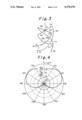
- FIG. 1 shows a structure of a quadrifilar helix antenna according to the present invention
- FIG. 2 shows the radiation pattern of a quadrifilar helix antenna of FIG. 1,
- FIG. 3 shows a structure of the second embodiment of the quadrifilar helix antenna according to the present invention
- FIG. 4 shows the radiation pattern of the quadrifilar helix antenna of FIG. 3,
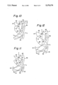
- FIG. 5 shows a structure of the third embodiment of a quadrifilar helix antenna according to the present invention
- FIG. 6 shows polarization characteristics of the sea-surface reflection waves, and the quadrifilar helix antenna of FIG. 5 in the sea-surface reflection direction
- FIG. 7 shows a prior quadrifilar helix antenna
- FIG. 8 shows the radiation pattern of the prior antenna of FIG. 7,
- FIG. 9 shows polarization characteristics of the sea-surface reflected waves, and the antenna in the sea-surface reflection direction in the prior art.
- FIG. 10 shows a structure of a quadrifilar helix antenna according to FIG. 1 incorporating linear short-circuiting conductors
- FIG. 11 shows a structure of a quadrifilar helix antenna according to FIG. 3 incorporating linear short-circuiting conductors
- FIG. 12 shows a structure of a quadrifilar helix antenna according to FIG. 5 incorporating linear short-circuiting conductors.
- FIG. 1 shows the quadrifilar helix antenna according to the present invention.
- the quadrifilar helix antenna has the feed circuit 41 which is located on the z-axis of the xyz rectangular coordinates system, four feed lines 42 through 45 extending from said feed circuit 41 so that those feed lines are perpendicular to one another and are parallel to the xy plane, four helix conductors 46 through 49 attached to one end of each of said feed lines so that the center axis of the helix coincides with the z-axis, and all the helixes are wound in the same direction, and four linear conductors 11 through 14 inserted between each of said feed lines 42-45 and each of said helix conductors 46-49 so that those linear conductors are parallel to the z-axis and all the linear conductors have the same length.
- each helix conductors which have no linear conductor attached, 46-49, may be open as shown in FIG. 1.
- each of said ends may be connected with one another by using linear conductors 51, 52 which are perpendicular to one another as shown in FIG. 10.
- FIG. 2 shows the radiation pattern of the antenna of FIG. 1.
- the parameters for FIG. 2 include that the length of the linear conductors 11-14 is 0.04 ⁇ , the pitch length of the helix conductors 46-49 is 1 ⁇ , the number of turns of each helix conductor 46-49 is 0.5, and the radius of the helix is 0.04 ⁇ , where ⁇ is the wavelength. It can be seen from FIG. 2 that he quadrifilar helix antenna with the above parameters has the wide beam, and excellent axis-ratio characteristics as compared with those of FIG. 8.
- the preferable parameter ranges of the antenna for providing the excellent characteristics in terms of the radiation pattern and axial ratio are 0.02-0.06 ⁇ for the length of the linear conductors 11-14, 0.9-1.1 ⁇ for the pitch length of the helix conductors 46-49, and 0.4-0.6 for the number of turns of the helix and 0.02-0.06 ⁇ for the radius of the helix.
- FIG. 3 shows the structure of the second embodiment of the present invention quadrifilar helix antenna.
- the quadrifilar helix antenna has the feed circuit 41 located on the z-axis of the xyz rectangular coordinates system, four feed lines 42 through 45 extending from said feed circuit 41 so that those feed lines are perpendicular to one another and are parallel to the xy plane, four helix conductors 46 through 49 attached to one end of each of the related feed lines so that the center axis of the helix coincides with the z-axis, and the winding direction of all the helixes is same, and four linear conductors 15 through 18 attached to one end of each of the helix conductors so that those linear conductors are parallel to the z-axis, and all the helix conductors have the same length.
- An opposite end of the linear conductors 15-18 at which no helix conductors are attached may be open as shown in FIG. 3.
- said ends may be short-circuited by using linear conductors 51, 52 perpendicular to one another as shown in FIG. 11.
- One example of the parameters which provide an excellent radiation pattern and axis-ratio characteristics is 0.04 ⁇ for the length of the linear conductors 11-14, 1 ⁇ for the pitch length of the helix conductors 46-49, 0.5 for the number of turns of the helix and 0.04 ⁇ for the radius of the helix.
- FIG. 4 shows the radiation pattern of the antenna which has the above parameters. It should be noted in FIG. 4 that the present antenna has a wide beam and good axis-ratio characteristics as compared with these FIG. 8. Since the radius of the present antenna is almost less than half that of the prior art of FIG. 8, the present invention may provide the smaller antenna.
- the preferable ranges of the antenna parameters to provide the excellent characteristics in terms of radiation pattern and axial ratio are 0.02-0.06 ⁇ for the length of the linear conductors 11-14, 0.9-1.1 ⁇ for the pitch length of the helix conductors 46-49, and 0.4-0.6 for the number of turns of the helix and 0.02-0.06 ⁇ for the radius of the helix.
- FIG. 5 shows the third embodiment of the present helix antenna.
- the antenna has the feed circuit 41 located on the z-axis of the xyz rectangular coordinates system, four feed lines 42-45 extending from said feed circuit 41 so that those feed lines are perpendicular to one another and are parallel to the xy plane, four helix conductors 46-49 so that the center axis coincides with the z-axis with all the helix conductors having the same winding direction.
- the first four linear conductors 11 through 14 are inserted between the feed lines 42-45, and the helix conductors 46-49 so that those linear conductors are parallel to the z-axis and all the linear conductors have the same length.
- the second four linear conductors 15 through 18 are attached to the other end of the helix conductors so that those linear conductors are parallel to the z-axis, and all have the same length.
- An opposite end of the linear conductors 15-18 at which no helix conductors are attached may be open as shown in FIG. 5.
- said ends may be short-circuited by using linear conductors 51, 52 perpendicular to each other as shown in FIG. 12.
- the structure of FIG. 5 can also provide the wide beam and the small size of the antenna which has less radius of the helix than that of the prior art shown in FIG. 7.
- the ranges of the parameters of the case of FIG. 5 to provide excellent characteristics in terms of radiation pattern and axial ratio are 0.02-0.06 ⁇ for the length of the first linear conductors 11-14, 0.02-0.06 ⁇ of the length of the second linear conductors 15-18, 0.9-1.1 ⁇ for the pitch length of the helix conductors 46-49, 0.4-0.6 for the number of turns of the helix and 0.02-0.06 ⁇ for the radius of the helix, where ⁇ is the wavelength.
- the embodiment of FIG. 5 has more freedom in determining the parameters to provide excellent characteristics as compared with those of FIG. 1 and FIG. 3.
- FIG. 6 shows the polarization characteristics of the sea-surface reflection wave and the present helix antenna which has the parameters of 0.04 ⁇ for the length of the first linear conductors 11-14, 0.04 ⁇ for the second length of the linear conductors 15-18, 1 ⁇ for the pitch length of the helix conductors 46-49, 0.5 for the number of turns of the helix, and 0.06 ⁇ for the radius of the helix.
- the numeral 64 shows the polarization characteristics in the sea-surface reflection direction (5 degrees below the horizon) of the present helix antenna.
- the major axis of the elliptical polarization of the present helix antenna in the sea-surface reflection direction (5-10 degrees below the horizon) is inclined by about 40 degree from the vertical polarization direction (50 degree from the sea-surface.)
- the direction of the major axis of the elliptical polarization of the present antenna has a large angle from that of the sea-surface reflection waves. Therefore, the multipath fading is expected to be reduced considerably.
- a fading depth of about 10 dB in the case of a prior antenna is observed, while that of about 7.5 dB in the case of the present antennas. Therefore, the amount of the fading depth is improved by 2.5 dB (about half for the required power) when the present invention is employed.
- the present antenna may have a wider range of parameters to provide the excellent antenna characteristics as compared with a prior antenna.
- a large design freedom is obtained.
- the size of the present antenna is smaller than that of the prior art antenna.
- the multipath fading which becomes a serious problem at a low elevation angle in the mobile satellite communication can be significantly reduced.
- a feed line, a linear conductor and a helix conductor may be either integral and can be made of a single conductive wire, or those members can be made of separate conductive wires which are coupled with one another.
Abstract
Description
Claims (11)
Applications Claiming Priority (2)
| Application Number | Priority Date | Filing Date | Title |
|---|---|---|---|
| JP2-44627 | 1990-02-27 | ||
| JP2044627A JP2586675B2 (en) | 1990-02-27 | 1990-02-27 | 4-wire helical antenna |
Publications (1)
| Publication Number | Publication Date |
|---|---|
| US5170176A true US5170176A (en) | 1992-12-08 |
Family
ID=12696666
Family Applications (1)
| Application Number | Title | Priority Date | Filing Date |
|---|---|---|---|
| US07/659,657 Expired - Lifetime US5170176A (en) | 1990-02-27 | 1991-02-25 | Quadrifilar helix antenna |
Country Status (3)
| Country | Link |
|---|---|
| US (1) | US5170176A (en) |
| JP (1) | JP2586675B2 (en) |
| GB (1) | GB2243724B (en) |
Cited By (36)
| Publication number | Priority date | Publication date | Assignee | Title |
|---|---|---|---|---|
| US5346300A (en) * | 1991-07-05 | 1994-09-13 | Sharp Kabushiki Kaisha | Back fire helical antenna |
| US5450093A (en) * | 1994-04-20 | 1995-09-12 | The United States Of America As Represented By The Secretary Of The Navy | Center-fed multifilar helix antenna |
| US5485170A (en) * | 1993-05-10 | 1996-01-16 | Amsc Subsidiary Corporation | MSAT mast antenna with reduced frequency scanning |
| US5541617A (en) * | 1991-10-21 | 1996-07-30 | Connolly; Peter J. | Monolithic quadrifilar helix antenna |
| US5587719A (en) * | 1994-02-04 | 1996-12-24 | Orbital Sciences Corporation | Axially arrayed helical antenna |
| US5594461A (en) * | 1993-09-24 | 1997-01-14 | Rockwell International Corp. | Low loss quadrature matching network for quadrifilar helix antenna |
| US5635945A (en) * | 1995-05-12 | 1997-06-03 | Magellan Corporation | Quadrifilar helix antenna |
| US5668565A (en) * | 1994-12-22 | 1997-09-16 | Orbital Science Corporation | Flexible feed line for an antenna system |
| US5721558A (en) * | 1996-05-03 | 1998-02-24 | Cta Space Systems, Inc. | Deployable helical antenna |
| US5861839A (en) * | 1997-05-19 | 1999-01-19 | Trw Inc. | Antenna apparatus for creating a 2D image |
| US5896113A (en) * | 1996-12-20 | 1999-04-20 | Ericsson Inc. | Quadrifilar helix antenna systems and methods for broadband operation in separate transmit and receive frequency bands |
| US5909196A (en) * | 1996-12-20 | 1999-06-01 | Ericsson Inc. | Dual frequency band quadrifilar helix antenna systems and methods |
| US5920292A (en) * | 1996-12-20 | 1999-07-06 | Ericsson Inc. | L-band quadrifilar helix antenna |
| US5977932A (en) * | 1994-02-04 | 1999-11-02 | Orbital Sciences Corporation | Self-deploying helical structure |
| US6011524A (en) * | 1994-05-24 | 2000-01-04 | Trimble Navigation Limited | Integrated antenna system |
| US6025816A (en) * | 1996-12-24 | 2000-02-15 | Ericsson Inc. | Antenna system for dual mode satellite/cellular portable phone |
| US6163302A (en) * | 1999-10-29 | 2000-12-19 | Telefonaktiebolaget Lm Ericsson (Publ) | Flexible dual-mode antenna for mobile stations |
| US6181298B1 (en) * | 1999-08-19 | 2001-01-30 | Ems Technologies Canada, Ltd. | Top-fed quadrafilar helical antenna |
| US6181297B1 (en) | 1994-08-25 | 2001-01-30 | Symmetricom, Inc. | Antenna |
| US6211840B1 (en) * | 1998-10-16 | 2001-04-03 | Ems Technologies Canada, Ltd. | Crossed-drooping bent dipole antenna |
| US6229499B1 (en) | 1999-11-05 | 2001-05-08 | Xm Satellite Radio, Inc. | Folded helix antenna design |
| US6300917B1 (en) | 1999-05-27 | 2001-10-09 | Sarantel Limited | Antenna |
| US6369776B1 (en) | 1999-02-08 | 2002-04-09 | Sarantel Limited | Antenna |
| US6459916B1 (en) * | 1996-04-16 | 2002-10-01 | Kyocera Corporation | Portable radio communication device |
| US6535179B1 (en) | 2001-10-02 | 2003-03-18 | Xm Satellite Radio, Inc. | Drooping helix antenna |
| US6552693B1 (en) | 1998-12-29 | 2003-04-22 | Sarantel Limited | Antenna |
| US20030206143A1 (en) * | 2002-05-03 | 2003-11-06 | Goldstein Mark Lawrence | Broadband quardifilar helix with high peak gain on the horizon |
| US6690336B1 (en) | 1998-06-16 | 2004-02-10 | Symmetricom, Inc. | Antenna |
| US20060208080A1 (en) * | 2004-11-05 | 2006-09-21 | Goliath Solutions Llc. | Distributed RFID antenna array utilizing circular polarized helical antennas |
| US20080094307A1 (en) * | 2006-10-24 | 2008-04-24 | Com Dev International Ltd. | Dual polarized multifilar antenna |
| US20080094308A1 (en) * | 2006-10-24 | 2008-04-24 | Com Dev International Ltd. | Dual polarized multifilar antenna |
| US8106846B2 (en) | 2009-05-01 | 2012-01-31 | Applied Wireless Identifications Group, Inc. | Compact circular polarized antenna |
| US8618998B2 (en) | 2009-07-21 | 2013-12-31 | Applied Wireless Identifications Group, Inc. | Compact circular polarized antenna with cavity for additional devices |
| US11183763B2 (en) | 2019-12-31 | 2021-11-23 | Atlanta RFtech LLC | Low profile dual-band quadrifilar antenna |
| US11303034B2 (en) | 2019-12-16 | 2022-04-12 | City University Of Hong Kong | Parallel-plate antenna |
| CN114995526A (en) * | 2022-08-02 | 2022-09-02 | 荣耀终端有限公司 | Method for guiding and adjusting pointing direction of satellite antenna and electronic equipment |
Families Citing this family (5)
| Publication number | Priority date | Publication date | Assignee | Title |
|---|---|---|---|---|
| AU693616B2 (en) * | 1994-12-06 | 1998-07-02 | Andrew Llc | A helical antenna |
| NO993414L (en) | 1998-07-22 | 2000-01-23 | Vistar Telecommunications Inc | Integrated antenna |
| GB2485084B (en) * | 2009-07-02 | 2014-10-01 | Elektrobit Wireless Comm Oy | Multiresonance helix antenna |
| JP6914598B2 (en) * | 2017-10-03 | 2021-08-04 | 日本アンテナ株式会社 | Circularly polarized antenna and diversity communication system |
| JP6906863B2 (en) * | 2017-10-03 | 2021-07-21 | 日本アンテナ株式会社 | Circularly polarized antenna and diversity communication system |
Citations (3)
| Publication number | Priority date | Publication date | Assignee | Title |
|---|---|---|---|---|
| US4396920A (en) * | 1979-12-09 | 1983-08-02 | David Grimberg | Broad-band small-size radio-frequency antenna system |
| US4658262A (en) * | 1985-02-19 | 1987-04-14 | Duhamel Raymond H | Dual polarized sinuous antennas |
| EP0241921A1 (en) * | 1986-04-15 | 1987-10-21 | Alcatel Espace | High-efficiency antenna |
Family Cites Families (3)
| Publication number | Priority date | Publication date | Assignee | Title |
|---|---|---|---|---|
| GB840850A (en) * | 1955-07-19 | 1960-07-13 | Telefunken Gmbh | Improvements relating to high frequency aerial-arrangements |
| JPS6330006A (en) * | 1986-07-23 | 1988-02-08 | Sony Corp | Helical antenna |
| JPS6454407U (en) * | 1987-09-29 | 1989-04-04 |
-
1990
- 1990-02-27 JP JP2044627A patent/JP2586675B2/en not_active Expired - Fee Related
-
1991
- 1991-02-25 US US07/659,657 patent/US5170176A/en not_active Expired - Lifetime
- 1991-02-26 GB GB9103984A patent/GB2243724B/en not_active Expired - Fee Related
Patent Citations (3)
| Publication number | Priority date | Publication date | Assignee | Title |
|---|---|---|---|---|
| US4396920A (en) * | 1979-12-09 | 1983-08-02 | David Grimberg | Broad-band small-size radio-frequency antenna system |
| US4658262A (en) * | 1985-02-19 | 1987-04-14 | Duhamel Raymond H | Dual polarized sinuous antennas |
| EP0241921A1 (en) * | 1986-04-15 | 1987-10-21 | Alcatel Espace | High-efficiency antenna |
Non-Patent Citations (8)
| Title |
|---|
| "Multielement, Fractional Turn Helices", Kilgus, IEEE Transactions On Antennas And Propagation, Jul., 1968, pp. 499-500. |
| "Resonant Quadrafilar Helix", Kilgus et al, IEEE Transactions On Antennas And Propagation, May, 1969, pp. 349-351. |
| "Shaped-Conical Radiation Pattern Performance of the Backfire Quadrifilar Helix", Kilgus, IEEE Transactions On Antennas And Propagation, May, 1975, pp. 392-397. |
| Kilgus, "Resonant Quadrifilar Helix Design" The Microwave Journal, Dec. 1970, pp. 49-54. |
| Kilgus, Resonant Quadrifilar Helix Design The Microwave Journal, Dec. 1970, pp. 49 54. * |
| Multielement, Fractional Turn Helices , Kilgus, IEEE Transactions On Antennas And Propagation, Jul., 1968, pp. 499 500. * |
| Resonant Quadrafilar Helix , Kilgus et al, IEEE Transactions On Antennas And Propagation, May, 1969, pp. 349 351. * |
| Shaped Conical Radiation Pattern Performance of the Backfire Quadrifilar Helix , Kilgus, IEEE Transactions On Antennas And Propagation, May, 1975, pp. 392 397. * |
Cited By (41)
| Publication number | Priority date | Publication date | Assignee | Title |
|---|---|---|---|---|
| US5346300A (en) * | 1991-07-05 | 1994-09-13 | Sharp Kabushiki Kaisha | Back fire helical antenna |
| US5541617A (en) * | 1991-10-21 | 1996-07-30 | Connolly; Peter J. | Monolithic quadrifilar helix antenna |
| US5485170A (en) * | 1993-05-10 | 1996-01-16 | Amsc Subsidiary Corporation | MSAT mast antenna with reduced frequency scanning |
| US5604972A (en) * | 1993-05-10 | 1997-02-25 | Amsc Subsidiary Corporation | Method of manufacturing a helical antenna |
| US5594461A (en) * | 1993-09-24 | 1997-01-14 | Rockwell International Corp. | Low loss quadrature matching network for quadrifilar helix antenna |
| US5977932A (en) * | 1994-02-04 | 1999-11-02 | Orbital Sciences Corporation | Self-deploying helical structure |
| US5587719A (en) * | 1994-02-04 | 1996-12-24 | Orbital Sciences Corporation | Axially arrayed helical antenna |
| US5450093A (en) * | 1994-04-20 | 1995-09-12 | The United States Of America As Represented By The Secretary Of The Navy | Center-fed multifilar helix antenna |
| US6011524A (en) * | 1994-05-24 | 2000-01-04 | Trimble Navigation Limited | Integrated antenna system |
| US6181297B1 (en) | 1994-08-25 | 2001-01-30 | Symmetricom, Inc. | Antenna |
| US5668565A (en) * | 1994-12-22 | 1997-09-16 | Orbital Science Corporation | Flexible feed line for an antenna system |
| US5635945A (en) * | 1995-05-12 | 1997-06-03 | Magellan Corporation | Quadrifilar helix antenna |
| US6459916B1 (en) * | 1996-04-16 | 2002-10-01 | Kyocera Corporation | Portable radio communication device |
| US5721558A (en) * | 1996-05-03 | 1998-02-24 | Cta Space Systems, Inc. | Deployable helical antenna |
| US5896113A (en) * | 1996-12-20 | 1999-04-20 | Ericsson Inc. | Quadrifilar helix antenna systems and methods for broadband operation in separate transmit and receive frequency bands |
| US5909196A (en) * | 1996-12-20 | 1999-06-01 | Ericsson Inc. | Dual frequency band quadrifilar helix antenna systems and methods |
| US5920292A (en) * | 1996-12-20 | 1999-07-06 | Ericsson Inc. | L-band quadrifilar helix antenna |
| US6025816A (en) * | 1996-12-24 | 2000-02-15 | Ericsson Inc. | Antenna system for dual mode satellite/cellular portable phone |
| US5861839A (en) * | 1997-05-19 | 1999-01-19 | Trw Inc. | Antenna apparatus for creating a 2D image |
| US6690336B1 (en) | 1998-06-16 | 2004-02-10 | Symmetricom, Inc. | Antenna |
| US6211840B1 (en) * | 1998-10-16 | 2001-04-03 | Ems Technologies Canada, Ltd. | Crossed-drooping bent dipole antenna |
| US6552693B1 (en) | 1998-12-29 | 2003-04-22 | Sarantel Limited | Antenna |
| US6369776B1 (en) | 1999-02-08 | 2002-04-09 | Sarantel Limited | Antenna |
| US6300917B1 (en) | 1999-05-27 | 2001-10-09 | Sarantel Limited | Antenna |
| US6181298B1 (en) * | 1999-08-19 | 2001-01-30 | Ems Technologies Canada, Ltd. | Top-fed quadrafilar helical antenna |
| US6163302A (en) * | 1999-10-29 | 2000-12-19 | Telefonaktiebolaget Lm Ericsson (Publ) | Flexible dual-mode antenna for mobile stations |
| US6229499B1 (en) | 1999-11-05 | 2001-05-08 | Xm Satellite Radio, Inc. | Folded helix antenna design |
| US6535179B1 (en) | 2001-10-02 | 2003-03-18 | Xm Satellite Radio, Inc. | Drooping helix antenna |
| US20030206143A1 (en) * | 2002-05-03 | 2003-11-06 | Goldstein Mark Lawrence | Broadband quardifilar helix with high peak gain on the horizon |
| US6812906B2 (en) * | 2002-05-03 | 2004-11-02 | Harris Corporation | Broadband quardifilar helix with high peak gain on the horizon |
| US7614556B2 (en) * | 2004-11-05 | 2009-11-10 | Goliath Solutions, Llc | Distributed RFID antenna array utilizing circular polarized helical antennas |
| US20060208080A1 (en) * | 2004-11-05 | 2006-09-21 | Goliath Solutions Llc. | Distributed RFID antenna array utilizing circular polarized helical antennas |
| US20080094307A1 (en) * | 2006-10-24 | 2008-04-24 | Com Dev International Ltd. | Dual polarized multifilar antenna |
| US20080094308A1 (en) * | 2006-10-24 | 2008-04-24 | Com Dev International Ltd. | Dual polarized multifilar antenna |
| US7817101B2 (en) | 2006-10-24 | 2010-10-19 | Com Dev International Ltd. | Dual polarized multifilar antenna |
| US8106846B2 (en) | 2009-05-01 | 2012-01-31 | Applied Wireless Identifications Group, Inc. | Compact circular polarized antenna |
| US8618998B2 (en) | 2009-07-21 | 2013-12-31 | Applied Wireless Identifications Group, Inc. | Compact circular polarized antenna with cavity for additional devices |
| US11303034B2 (en) | 2019-12-16 | 2022-04-12 | City University Of Hong Kong | Parallel-plate antenna |
| US11183763B2 (en) | 2019-12-31 | 2021-11-23 | Atlanta RFtech LLC | Low profile dual-band quadrifilar antenna |
| CN114995526A (en) * | 2022-08-02 | 2022-09-02 | 荣耀终端有限公司 | Method for guiding and adjusting pointing direction of satellite antenna and electronic equipment |
| CN114995526B (en) * | 2022-08-02 | 2023-01-10 | 荣耀终端有限公司 | Method for guiding and adjusting pointing direction of satellite antenna and electronic equipment |
Also Published As
| Publication number | Publication date |
|---|---|
| GB2243724B (en) | 1994-04-06 |
| GB2243724A (en) | 1991-11-06 |
| JP2586675B2 (en) | 1997-03-05 |
| GB9103984D0 (en) | 1991-04-10 |
| JPH03248603A (en) | 1991-11-06 |
Similar Documents
| Publication | Publication Date | Title |
|---|---|---|
| US5170176A (en) | Quadrifilar helix antenna | |
| US4115782A (en) | Microwave antenna system | |
| US5173715A (en) | Antenna with curved dipole elements | |
| US3906509A (en) | Circularly polarized helix and spiral antennas | |
| JP3089933B2 (en) | Antenna device | |
| US5255005A (en) | Dual layer resonant quadrifilar helix antenna | |
| US6320553B1 (en) | Multiple frequency reflector antenna with multiple feeds | |
| US6184845B1 (en) | Dielectric-loaded antenna | |
| CA2233637C (en) | Composite antenna | |
| US5450093A (en) | Center-fed multifilar helix antenna | |
| AU618804B2 (en) | Monopole/l-shaped parasitic elements for circularly/ eliptically polarized wave transceiving | |
| US6133891A (en) | Quadrifilar helix antenna | |
| US5099249A (en) | Microstrip antenna for vehicular satellite communications | |
| US5467095A (en) | Low profile antenna | |
| US4369449A (en) | Linearly polarized omnidirectional antenna | |
| US3681772A (en) | Modulated arm width spiral antenna | |
| EP3314694B1 (en) | Multi-filar helical antenna | |
| US6545649B1 (en) | Low backlobe variable pitch quadrifilar helix antenna system for mobile satellite applications | |
| US3618114A (en) | Conical logarithmic-spiral antenna | |
| EP0431764B1 (en) | Antenna with curved dipole elements | |
| EP0777920B1 (en) | Nonsquinting end-fed quadrifilar helical antenna | |
| US4315264A (en) | Circularly polarized antenna with circular arrays of slanted dipoles mounted around a conductive mast | |
| JPH07283651A (en) | Nondirectional antenna, nondirectional vhf antenna, nondirectional uhf antenna, and nondirectional vhf/uhf antenna | |
| CN113922059A (en) | Conical helical antenna | |
| Sakaguchi et al. | A circularly polarized omnidirectional small helical antenna |
Legal Events
| Date | Code | Title | Description |
|---|---|---|---|
| AS | Assignment |
Owner name: KOKUSAI DENSHIN DENWA CO., LTD., 3-2, NISHI-SHINJU Free format text: ASSIGNMENT OF ASSIGNORS INTEREST.;ASSIGNORS:YASUNAGA, MASAYUKI;SHIOKAWA, TAKAYASU;REEL/FRAME:005618/0787 Effective date: 19910212 |
|
| FEPP | Fee payment procedure |
Free format text: PAYER NUMBER DE-ASSIGNED (ORIGINAL EVENT CODE: RMPN); ENTITY STATUS OF PATENT OWNER: LARGE ENTITY Free format text: PAYOR NUMBER ASSIGNED (ORIGINAL EVENT CODE: ASPN); ENTITY STATUS OF PATENT OWNER: LARGE ENTITY |
|
| STCF | Information on status: patent grant |
Free format text: PATENTED CASE |
|
| FEPP | Fee payment procedure |
Free format text: PAYOR NUMBER ASSIGNED (ORIGINAL EVENT CODE: ASPN); ENTITY STATUS OF PATENT OWNER: LARGE ENTITY |
|
| FPAY | Fee payment |
Year of fee payment: 4 |
|
| FPAY | Fee payment |
Year of fee payment: 8 |
|
| AS | Assignment |
Owner name: KDD CORPORATION, JAPAN Free format text: CHANGE OF NAME;ASSIGNOR:KOKUSAI DENSHIN DENWA CO., LTD.;REEL/FRAME:013835/0725 Effective date: 19981201 |
|
| AS | Assignment |
Owner name: DDI CORPORATION, JAPAN Free format text: MERGER;ASSIGNOR:KDD CORPORATION;REEL/FRAME:013957/0664 Effective date: 20001001 |
|
| AS | Assignment |
Owner name: KDDI CORPORATION, JAPAN Free format text: CHANGE OF NAME;ASSIGNOR:DDI CORPORATION;REEL/FRAME:014083/0804 Effective date: 20010401 |
|
| FPAY | Fee payment |
Year of fee payment: 12 |