US5167528A - Method of manufacturing an electrical connector - Google Patents

Method of manufacturing an electrical connector Download PDF

Info

Publication number
US5167528A
US5167528A US07/685,656 US68565691A US5167528A US 5167528 A US5167528 A US 5167528A US 68565691 A US68565691 A US 68565691A US 5167528 A US5167528 A US 5167528A
Authority
US
United States
Prior art keywords
contactors
housings
free end
base
connector
Prior art date
Legal status (The legal status is an assumption and is not a legal conclusion. Google has not performed a legal analysis and makes no representation as to the accuracy of the status listed.)
Expired - Lifetime
Application number
US07/685,656
Inventor
Youichi Nishiyama
Hisahiro Ono
Current Assignee (The listed assignees may be inaccurate. Google has not performed a legal analysis and makes no representation or warranty as to the accuracy of the list.)
Panasonic Electric Works Co Ltd
Original Assignee
Matsushita Electric Works Ltd
Priority date (The priority date is an assumption and is not a legal conclusion. Google has not performed a legal analysis and makes no representation as to the accuracy of the date listed.)
Filing date
Publication date
Priority claimed from JP4284990U external-priority patent/JPH0472471U/ja
Priority claimed from JP3030386A external-priority patent/JP2871128B2/en
Application filed by Matsushita Electric Works Ltd filed Critical Matsushita Electric Works Ltd
Assigned to MATSUSHITA ELECTRIC WORKS, LTD., 1048, OAZA-KADOMA, KADOMA-SHI, OSAKA 571, JAPAN A CORP OF JAPAN reassignment MATSUSHITA ELECTRIC WORKS, LTD., 1048, OAZA-KADOMA, KADOMA-SHI, OSAKA 571, JAPAN A CORP OF JAPAN ASSIGNMENT OF ASSIGNORS INTEREST. Assignors: NISHIYAMA, YOUICHI, ONO, HISAHIRO
Application granted granted Critical
Publication of US5167528A publication Critical patent/US5167528A/en
Assigned to PANASONIC ELECTRIC WORKS CO., LTD. reassignment PANASONIC ELECTRIC WORKS CO., LTD. CHANGE OF NAME (SEE DOCUMENT FOR DETAILS). Assignors: MATSUSHITA ELECTRIC WORKS, LTD.
Anticipated expiration legal-status Critical
Expired - Lifetime legal-status Critical Current

Links

Images

Classifications

    • HELECTRICITY
    • H01ELECTRIC ELEMENTS
    • H01RELECTRICALLY-CONDUCTIVE CONNECTIONS; STRUCTURAL ASSOCIATIONS OF A PLURALITY OF MUTUALLY-INSULATED ELECTRICAL CONNECTING ELEMENTS; COUPLING DEVICES; CURRENT COLLECTORS
    • H01R9/00Structural associations of a plurality of mutually-insulated electrical connecting elements, e.g. terminal strips or terminal blocks; Terminals or binding posts mounted upon a base or in a case; Bases therefor
    • HELECTRICITY
    • H01ELECTRIC ELEMENTS
    • H01RELECTRICALLY-CONDUCTIVE CONNECTIONS; STRUCTURAL ASSOCIATIONS OF A PLURALITY OF MUTUALLY-INSULATED ELECTRICAL CONNECTING ELEMENTS; COUPLING DEVICES; CURRENT COLLECTORS
    • H01R43/00Apparatus or processes specially adapted for manufacturing, assembling, maintaining, or repairing of line connectors or current collectors or for joining electric conductors
    • H01R43/20Apparatus or processes specially adapted for manufacturing, assembling, maintaining, or repairing of line connectors or current collectors or for joining electric conductors for assembling or disassembling contact members with insulating base, case or sleeve
    • H01R43/24Assembling by moulding on contact members
    • HELECTRICITY
    • H01ELECTRIC ELEMENTS
    • H01RELECTRICALLY-CONDUCTIVE CONNECTIONS; STRUCTURAL ASSOCIATIONS OF A PLURALITY OF MUTUALLY-INSULATED ELECTRICAL CONNECTING ELEMENTS; COUPLING DEVICES; CURRENT COLLECTORS
    • H01R12/00Structural associations of a plurality of mutually-insulated electrical connecting elements, specially adapted for printed circuits, e.g. printed circuit boards [PCB], flat or ribbon cables, or like generally planar structures, e.g. terminal strips, terminal blocks; Coupling devices specially adapted for printed circuits, flat or ribbon cables, or like generally planar structures; Terminals specially adapted for contact with, or insertion into, printed circuits, flat or ribbon cables, or like generally planar structures
    • H01R12/70Coupling devices
    • H01R12/71Coupling devices for rigid printing circuits or like structures
    • H01R12/712Coupling devices for rigid printing circuits or like structures co-operating with the surface of the printed circuit or with a coupling device exclusively provided on the surface of the printed circuit
    • H01R12/716Coupling device provided on the PCB
    • HELECTRICITY
    • H01ELECTRIC ELEMENTS
    • H01RELECTRICALLY-CONDUCTIVE CONNECTIONS; STRUCTURAL ASSOCIATIONS OF A PLURALITY OF MUTUALLY-INSULATED ELECTRICAL CONNECTING ELEMENTS; COUPLING DEVICES; CURRENT COLLECTORS
    • H01R12/00Structural associations of a plurality of mutually-insulated electrical connecting elements, specially adapted for printed circuits, e.g. printed circuit boards [PCB], flat or ribbon cables, or like generally planar structures, e.g. terminal strips, terminal blocks; Coupling devices specially adapted for printed circuits, flat or ribbon cables, or like generally planar structures; Terminals specially adapted for contact with, or insertion into, printed circuits, flat or ribbon cables, or like generally planar structures
    • H01R12/70Coupling devices
    • H01R12/71Coupling devices for rigid printing circuits or like structures
    • H01R12/72Coupling devices for rigid printing circuits or like structures coupling with the edge of the rigid printed circuits or like structures
    • H01R12/73Coupling devices for rigid printing circuits or like structures coupling with the edge of the rigid printed circuits or like structures connecting to other rigid printed circuits or like structures
    • HELECTRICITY
    • H01ELECTRIC ELEMENTS
    • H01RELECTRICALLY-CONDUCTIVE CONNECTIONS; STRUCTURAL ASSOCIATIONS OF A PLURALITY OF MUTUALLY-INSULATED ELECTRICAL CONNECTING ELEMENTS; COUPLING DEVICES; CURRENT COLLECTORS
    • H01R13/00Details of coupling devices of the kinds covered by groups H01R12/70 or H01R24/00 - H01R33/00
    • H01R13/02Contact members
    • H01R13/28Contacts for sliding cooperation with identically-shaped contact, e.g. for hermaphroditic coupling devices
    • HELECTRICITY
    • H01ELECTRIC ELEMENTS
    • H01RELECTRICALLY-CONDUCTIVE CONNECTIONS; STRUCTURAL ASSOCIATIONS OF A PLURALITY OF MUTUALLY-INSULATED ELECTRICAL CONNECTING ELEMENTS; COUPLING DEVICES; CURRENT COLLECTORS
    • H01R4/00Electrically-conductive connections between two or more conductive members in direct contact, i.e. touching one another; Means for effecting or maintaining such contact; Electrically-conductive connections having two or more spaced connecting locations for conductors and using contact members penetrating insulation
    • H01R4/02Soldered or welded connections
    • H01R4/028Soldered or welded connections comprising means for preventing flowing or wicking of solder or flux in parts not desired
    • HELECTRICITY
    • H01ELECTRIC ELEMENTS
    • H01RELECTRICALLY-CONDUCTIVE CONNECTIONS; STRUCTURAL ASSOCIATIONS OF A PLURALITY OF MUTUALLY-INSULATED ELECTRICAL CONNECTING ELEMENTS; COUPLING DEVICES; CURRENT COLLECTORS
    • H01R43/00Apparatus or processes specially adapted for manufacturing, assembling, maintaining, or repairing of line connectors or current collectors or for joining electric conductors
    • H01R43/16Apparatus or processes specially adapted for manufacturing, assembling, maintaining, or repairing of line connectors or current collectors or for joining electric conductors for manufacturing contact members, e.g. by punching and by bending
    • YGENERAL TAGGING OF NEW TECHNOLOGICAL DEVELOPMENTS; GENERAL TAGGING OF CROSS-SECTIONAL TECHNOLOGIES SPANNING OVER SEVERAL SECTIONS OF THE IPC; TECHNICAL SUBJECTS COVERED BY FORMER USPC CROSS-REFERENCE ART COLLECTIONS [XRACs] AND DIGESTS
    • Y10TECHNICAL SUBJECTS COVERED BY FORMER USPC
    • Y10TTECHNICAL SUBJECTS COVERED BY FORMER US CLASSIFICATION
    • Y10T29/00Metal working
    • Y10T29/49Method of mechanical manufacture
    • Y10T29/49002Electrical device making
    • Y10T29/49117Conductor or circuit manufacturing
    • Y10T29/49204Contact or terminal manufacturing
    • Y10T29/49208Contact or terminal manufacturing by assembling plural parts
    • Y10T29/4922Contact or terminal manufacturing by assembling plural parts with molding of insulation
    • YGENERAL TAGGING OF NEW TECHNOLOGICAL DEVELOPMENTS; GENERAL TAGGING OF CROSS-SECTIONAL TECHNOLOGIES SPANNING OVER SEVERAL SECTIONS OF THE IPC; TECHNICAL SUBJECTS COVERED BY FORMER USPC CROSS-REFERENCE ART COLLECTIONS [XRACs] AND DIGESTS
    • Y10TECHNICAL SUBJECTS COVERED BY FORMER USPC
    • Y10TTECHNICAL SUBJECTS COVERED BY FORMER US CLASSIFICATION
    • Y10T29/00Metal working
    • Y10T29/49Method of mechanical manufacture
    • Y10T29/49002Electrical device making
    • Y10T29/49117Conductor or circuit manufacturing
    • Y10T29/49204Contact or terminal manufacturing
    • Y10T29/49208Contact or terminal manufacturing by assembling plural parts
    • Y10T29/49222Contact or terminal manufacturing by assembling plural parts forming array of contacts or terminals

Landscapes

  • Engineering & Computer Science (AREA)
  • Manufacturing & Machinery (AREA)
  • Coupling Device And Connection With Printed Circuit (AREA)

Abstract

A connector includes a pair of housings mutually engageable integrally, and a plurality of contactors secured at their base portions to each of the housings so that the contactors of the both housings are contactable with each other respectively at their free ends when the housings are engaged integral to each other, mutually with a clicking resiliency provided by means of a sloped step made in each contactor between the base and free end portions, whereby the contactor capable of providing a reliable clicking action denoting completion of the connection is rendered manufacturable without requiring highly precise administration.

Description

BACKGROUND OF THE INVENTION
This invention relates to connectors and methods for manufacturing the same.
The connectors of the kind referred to find their utility specifically when used at a multiple-wire connecting section in various types of wiring systems.
DESCRIPTION OF RELATED ART
For the connector of the kind referred to, an example has been disclosed in Japanese Laid-Open Utility Model Publication of A. Shimada, in which one of a pair of housings made of a synthetic resin is formed to have a projecting wall while the other housing is provided with a recess for accommodating the projecting wall so that the both housings will be engageable with each other, contactors of bar-shaped conducting metal material are provided on both sides of the projecting wall and opposing side walls of the recess, and the corresponding ones of the contactors are mutually contactable upon the engagement of the both housings.
In this instance of the known connector, the contactors are provided in the identical configuration throughout the ones on both sides of the projecting wall of the one housing and the ones on the opposing side walls of the recess of the other housing, so that these conductors are embedded at their base end portion in the housings while they are respectively provided with a tapered face slanted toward free end portion and swelled at the free end to be a contacting part by means of an expanding work or the like, corresponding ones of the contactors come into contact with each other at two points when the pair of the housing are engaged to each other so as to attain a highly reliable connection between the contactors of the both housings.
In the engagement of the both connector housings, however, the swelled contacting parts are caused to simply slide along the tapered face, so that it has been uneasy to clearly determine with finger tip of the like tactile sense and, if the contactors are inserted beyond a proper contacting degree between the contactors, there arises a problem that the housings are thereby caused to be damaged. While it may be possible, on the other hand, to arrange the contactors so that corresponding ones of the contactors are properly brought into contact at two points with each other when the pair of the housings are intimately engaged to each other, the tapered faces of the respective contactors are required to be so controlled as to be constant in the tapered angle, whereby it is made necessary to execute the expansion work or the like with a highly controlled amount of the working, and there arises a problem that the manufacture becomes extremely complicated. This tendency becomes more remarkable as the contactors are made smaller and, when the contactors are formed through the expansion work, it becomes more complicated to deal with expansion fins as the contactors are made smaller, so as to render the manufacture to be difficult in general, to be detrimental in elevated costs.
SUMMARY OF THE INVENTION
A primary object of the present invention is, therefore, to provide a connector which is capable of allowing the connecting and disconnecting operation to be smoothly performed, providing a reliable clicking action upon completion of the connection to assure a clear tactility of the connection completion, and rendering the manufacture to be extremely easy and inexpensive while still allowing the size of the connector to be sufficiently minimized.
According to the present invention, this object can be established by a connector in which a pair of housings are provided for being mutually engageable, and contactors made to have an elasticity are secured at their base portions to each of the housings to be mutually resiliently brought into contact at contacting parts formed at free ends, wherein the contactors are provided respectively with a sloped step between the secured base portion and the free end for providing a clicking action.
Other objects and advantages of the present invention shall be made clear in following description of the invention shall be made clear in following description of the invention detailed with reference to accompanying drawings.
BRIEF EXPLANATION OF DRAWINGS
FIG. 1 shows in a cross section of an embodiment of the connector according to the present invention, shown in mutual engaging state of a pair of housings;
FIG. 2 is a side elevation of one of the housings of the connector shown in FIG. 1, with a part of the housing shown as removed;
FIG. 3 shows in a perspective view one of contactors employed in the connector of FIG. 1;
FIG. 4 is an explanatory view for contacting state between the contactors of the both housings forming the connector of FIG. 1;
FIG. 5 is an explanatory view for a state in which the clicking action is attained in the connector of FIG. 1;
FIG. 6 is a diagram for showing the relationship between the engaging strength and the engaging stroke of the contactors in the connector of FIG. 1;
FIG. 7 are explanatory views for the sequence of the contacting operation between the contactors of the both housings of the connector shown in FIG. 1;
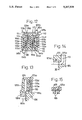
FIG. 8 shows in a cross section of one of the housings in another embodiment of the connector according to the present invention;
FIG. 9 is a plan view of the housing of the connector shown in FIG. 8;
FIG. 10 is a side elevation of the housing of the connector shown in FIG. 8 with a part of the housing shown as removed;
FIG. 11 is a bottom view of the housing of the connector shown in FIG. 8;
FIG. 12 shows in a cross section of the connector shown in FIG. 8 with the both housings in engaging state;
FIGS. 13 and 14 are fragmentary sectioned views of dies employed for manufacturing the connector of FIG. 8;
FIG. 15 is a fragmentary sectioned view of the dies of FIG. 14 taken along line XV-XV;
FIGS. 16 and 17 are explanatory views for a couple of parts of manufacturing steps of the connector shown in FIG. 8;
FIG. 18 shows in a perspective view one of the housings employed in a further embodiment of the connector according to the present invention;
FIG. 19 is a side elevation of the connector of FIG. 18 in the engaging state of the both housings;
FIG. 20 is a front view of the connector of FIG. 18 in the engaging state;
FIG. 21 shows in a fragmentary perspective view in still another embodiment of the connector according to the present invention, with the both housings shown as disengaged from each other; and
FIG. 22 is a fragmentary sectioned view in locking state of locking metal fittings employed in the connector of FIG. 21.
While the present invention shall now be described with reference to the preferred embodiments shown in the accompanying drawings, it should be appreciated that its intention is not to limit the present invention only to such embodiments shown but rather to include all alterations, modifications and equivalent arrangements possible within the scope of appended claims.
DETAILED DESCRIPTION OF THE PREFERRED EMBODIMENTS
Referring to FIGS. 1 to 3, a connector 10 according to the present invention comprises a pair of housings 11 and 12, which are formed with a synthetic resin material mutually into an identical configuration, preferably in a box shape. In their endwise view, the housings 11 and 12 respectively comprise one longitudinal half 11a or 12a and the other longitudinal half 11b or 12b, which two halves 11a and 11b or 12a and 12b are defining between them a groove 11c or 12c, the one half 11a or 12a is formed relatively smaller than the other half 11b or 12b, and the both housings 11 and 12 are formed to be mutually engageable, with the respective halves disposed to interdigitate so that the one half 11a of the one housing 11 will be disposed inside the other half 12b of the other housing 12 while the other half 11b of the one housing 11 will be disposed outside the one half 12a of the other housing 12.
In the respective housings 11 and 12, two arrays of contactors 13 and 14 are provided as disposed along the inner side wall of their one halves 11a and 12a, as seen in FIG. 1, while these contactors 13 and 14 are formed as punched out of flat and thin metal plate and formed substantially into a bar shape with such conducting metal material as a copper alloy and the like, as shown in FIG. 3. The respective contactors 13 and 14 are secured at their base portions 13a and 14a as urged into holding holes 15 and 16 made in bottom wall parts of the one halves 11a and 12a while extended ends 13b and 14b out of the bottom wall parts are bent outward into an L-shape. Along the inner side walls of the other halves 11b and 12b of the both housings 11 and 12. Further, along the inner side walls of the other halves 11b and 12b of the both housings 11 and 12, further two arrays of contactors 17 and 18 formed in the same manner as the foregoing contactors 13 and 14 are provided, so that the contactors 17 and 18 are also urged at their base portions 17a and 18a into holding holes 19 and 20 made in bottom wall parts of the other halves 11b and 12b of the both housings 11 and 12 while extended ends 17b and 18b out of the bottom wall parts are bent outward also into an L-shape.
The foregoing arrays of the contactors 13, 14 and 17, 18 are respectively made to be the same number of the conductors, so that a concurrent connection of multiple wires may be realized (since the arrangement of the respective arrays of the contactors 13, 14, 17 and 18 are substantially the same and, in FIG. 2, the housing 11 and the contactor array 13 disposed along the one half 11a of the housing 11 only are shown in FIG. 2). In this case, the extended ends 13b, 14b and 17b, 18b bent into the L-shape are disposed to extend mutually in opposite directions on the bottom wall parts of the housings 11 and 12, that is, adjacent to non-open side of the housings, so as to allow the connector to be easily mounted to, for example, a printed circuit substrate (not shown). Further, at both longitudinal end portions of the housings 11 and 12, there are provided upward and downward projections 21a and 21b for positioning the connector to the printed circuit substrate, as well as fixing metal terminals 22a and 22b, preferably, for mounting the connector to the printed circuit substrate (while FIG. 2 shows only the one housing 11, the other housing 12 is formed substantially in the same manner).
The contactors 13, 14, 17 and 18 shall now be detailed with reference to FIG. 3 but, since they are substantially all in identical formation, only one of the contactors 13 will be explained here as an example. That is, the contactor 13 is formed to have at a free end portion 13c a contacting part 13d bent into an L-shape at a relatively shallow angle and provided with a plating of such a noble metal as gold or the like which is excellent in the electric contact stability. Between the base portion 13a and the free end portion 13c, there is provided a slanted step 13e formed at an angle of about 30 degrees, preferably, so as to allow a reliable clicking action to be attained upon completion of the connection between the respective contactors of the both housing. It is preferable that these contacting part 13d and slanted step 13e are formed by means of a bending process with proper dies or the like since, according to such process, the required working can be easily executed even when a sufficient size minimization is attempted, with a higher precisioned work stably executed, in contrast to conventional expanding work. At the base portions 13a of the contactor 13, further, there are provided such projections 13f that will frictionally engage with inner face of the holding hole 15. All other contactors 14, 17 and 18 are formed in the same manner as the contactor 13 and their respective portions are denoted with the same suffixes as given to the contactor 13 in the drawings.
Now, as the housings 11 and 12 formed in a pair as has been described are engaged to each other, the respective arrays of the contactors 13 and 18 as well as 17 and 14 are also brought into resilient engagement with each other while mutually being caused to bendingly deform so as to come into a reliable contacting state at two points through their contacting parts 13d and 18d as well as 17d and 14d. That is, as shown in FIG. 4, the mutually opposing pair of the contactors 13 and 18 or 14 and 17 are made to engage at their contacting parts 13d and 18d or 14d and 17d with a portion closer to the base portions of the opposing contactors, while being resiliently bent by one another, so that, as represented by a solid line curve x of the relationship between the engaging strength and the engaging stroke of FIG. 6, in particular, by a portion between two points B and E of the curve, with the engaging strength between the opposing contactors varied relatively gradually so as to allow the both housings 11 and 12 to be engageable smoothly simply with finger tips or the like. During this engaging operation, the mutually sliding contacting parts 13d and 18d or 14d and 17d are caused to hit and pass the sloped steps 18e and 13e or 17e and 14e (see FIG. 5), upon which the mutual engaging strength is caused to become abruptly large to reach the maximum value and again abruptly smaller as is evident from a portion of the curve x adjacent a point E of FIG. 6, whereby a clicking action is provided to the finger tips so as to allow the completion of the contacting operation sensed by the operator.
Referring more in detail to the contacting operation of the connector according the present invention with reference also to FIGS. 7(A) to 7(F), a gradual engagement of the pair of the housings 11 and 12 with each other causes the opposing contactors 13 and 18, for example, initially to hit each other at their contacting parts 13d and 18d as seen in FIG. 7(A), then to be slightly bent in mutually separating direction while keeping mutual engagement as seen in FIG. 7(B), and thereafter to once flex back after passing through the contacting parts 13d and 18d so as to mutually resiliently with each other at two points as seen in FIG. 7(C). Up to this moment, the engaging strength is caused to vary as represented by a portion between points A and C of the solid line curve x in FIG. 6, in which the engaging strength in initial period of the contacting operation is once increased abruptly as is evident from a portion adjacent the point B of the curve x to allow the operator to sense the initiation of the contacting operation. Further, as the engaging strangth applied to the both housings 11 and 12 is increasingly continued, the tip end contacting parts 13d and 18d of the contactors 13 and 18 come to ride on the sloped steps 18e and 13e as shown in FIG. 7(D), and the contacting parts 13d and 18d slidingly passed through the sloped steps 18e and 13e as in FIG. 7(E) are brought into resilient contact with the contactors 18 and 13 at their portions closer to the base portions as in FIG. 7(F) so that the contactors 13 and 18 are brought into contact with each other mutually at two points with a high resilient contacting force, during which the engaging strength will vary as represented by a part following the point C and between points D and F of the solid line curve x in FIG. 6, as will be readily appreciated. Further, the variation in the engaging strength between the both housings of the connector of the present invention, as represented by the solid line curve x in FIG. 6, is more abrupt than that of a known connector as represented by a broken line curve y also shown in FIG. 6 so that, as will be also readily appreciated, an excellent clicking action can be attained.
In FIGS. 8 to 12, there is shown another embodiment of the connector according to the present invention, in which the respective arrays of the contactors are secured as integrally molded with the respective housings. In these drawings, the substantially identical constituent members with those in the foregoing embodiment of FIGS. 1-7 are denoted by the same reference numerals as used in FIGS. 1-7 but as added by 100. Referring more specifically to the present embodiment, the four arrays of the contactors 113, 114, 117 and 118 are formed as bent substantially into a Z-shape at their part from the base portions 113a to the externally extended ends 113b, 114b, 117b and 118b, and are integrally molded along the respective halves 111a, 111b, 112a and 112b of the both housings 111 and 112 as embedded therein at an intermediate portions of the Z-shape bent parts. Further, the contactors 113, 114, 117 and 118 are so arranged that their parts including the free end portions 113c, 114c, 117c and 118c having the shallow L-shaped contacting parts 113d, 114d, 117d and 118d as well as the sloped steps 113e, 114e, 117e and 118e are extended along the inner side faces of the housing halves 111a, 111b, 112a and 112b while the other extended ends 113b and 117b out of the housing 111 as well as the extended ends 114b and 118b out of the housing 112 are disposed to extend mutually in opposite directions, for ready mounting of the connector to the printed circuit substrate (not shown).
In the bottom wall parts of the housings 111 and 112, further, there are provided through holes 123a, 123b, 124a and 124b at positions adjacent to securing positions of the contactors 113, 114, 117 and 118, so that these through holes will function as discharge ports for a cleaning liquid.
In the present embodiment, too, the mutual engagement of the both housings 111 and 112 causes the mutually opposing arrays of the contactors 113 and 118 as well as 117 and 114 to resiliently bend each other and eventually to be brought into the reliable contacting state as optimumly resiliently contacted at the two points with each other, throught the substantially the same sequences of the variation in the engaging strength as shown in FIG. 6 and providing the excellent clicking action upon the completion of the connecting operation (as seen particularly in FIG. 12). In addition, according to the present embodiment, the Z-shaped bending of the respective contactors will be effective to soften any shock applied when the opposing contactors are mutually engaged upon the engagement of the housings 111 and 112. Further, with the integral molding of the contactors 113, 114, 117 and 118 with the housings 111 and 112, it is made possible to render the length of a range for which the contactors directly contact with the housings to be larger, so as to be able to firmly secure the respective contactors to the housings. On the other hand, the contactors are to be partly embedded in the housings as integrally molded therewith, so that a reinforcement can be provided to the housings. Further, since the contactors are to be firmly secured to the housings while an effective reinforcement of the housings can be realized at their portions where the contactors are molded integrally with the housings, it is made possible to render the thickness of the bottom wall parts of the housings 111 and 112 to be smaller though the through holes 123a, 123b and 124a, 124b are made in the portions, and thus to effectively reduce the entire height of the connector.
Next, the steps for integrally molding the contactors 113, 114, 117 and 118 with the housings 111 and 112 shall be described with reference to one of the contactors 113 as an example. That is, as shown in FIG. 13, an upper molding die 125 is provided with a recess 125a for accommodating therein the free end part 113c of the contactor 113, a partition 125c is provided to the die 125 between the recess 125b for integrally forming the half 111a of the housing 111 and, along bottom end face of this partition 125c, a so-called parting line, there is provided a groove 125d substantially of an identical width with that of the contactor 113 at its intermediate portion bent into the Z-shape (see FIGS. 15 and 16). The contactor 113 is thus inserted at the intermediate portion into the groove 125d, and a lower die 126 is fitted to the upper die 125 with a corner of the lower die 126 engaged to a part of the intermediate portion in the base portion 113a of the contactor 113 inserted in the groove 125d of the upper die 125 to thereby close the recess 125a, as shown in FIG. 14. Then, the base portion 113a of the contactor 113 inserted in the recess 125b of the upper die 125 and exposed out of the lower die 126 is bent at a proper position, and a synthetic resin is poured into the recess 125b and into a cavity defined between a slide core 126a and the lower die 126, whereby the housing 113 and the intermediate portion at the base portion 113a of the contactor 113 can be integrally molded. In this event, the other recess 125a of the upper die 125 is closed by the lower die 126 and base portion 113a of the contactor 113 so that no synthetic resin will enter therein. Thereafter, the extended end 113b of the contactor 113 is subjected to a bending work at a position closer to the bottom wall face of the housing 111. Provided at this time that a distance between the bottom wall face of the housing 111 and the bent position at the extended portion 113b of the contactor 113 is kept small, it is made possible to execute reliably a soldering work of the extended end 113b with respect to the printed circuit substrate 127 as shown in FIG. 17 even when the solder 127a is apt to flow upward along the extended end 113b of the contactor 113, without causing a so-called wicking phenomenon as restricted by the bottom wall face of the housing 111. Further, the extended ends 113b and 117b as well as 114b and 118b of the respective arrays of the connectors 113 and 114 as well as 114 and 118 respectively disposed to oppose each other are extended mutually in opposite directions so that a space between these extended ends can be well utilized as a vacant space and, in mounting the connector to the printed circuit substrate 127, a highly dense wiring can be provided onto the substrate 127 immediately below the connector.
In the above described embodiment with reference to FIGS. 8 to 17, other constituent elements and their function are the same as those in the foregoing embodiment of FIGS. 1 to 7.
In FIGS. 18 to 20, there is shown still another embodiment of the connector according to the present invention, in which the both housings 211 and 212 are provided at their both longitudinal end faces with each of a pair of engaging metal fittings 222A and 222B, as secured thereto by means of, for example, an integral molding. Each of the metal fittings 222A and 222B comprises a notch 222Aa or 222Ba and a projection 222Ab or 222Bb, so that the projection 222Bb of the metal fitting 222B will engage in the notch 222Aa of the metal fitting 222A while the projection 222Ab of the metal fitting 222A will engage in the notch 222Ba of the metal fitting 222B, whereby, when the both housings 211 and 212 are mutually disconnected, they can be effectively guided in their separating direction by means of the projections and notches even when any twisting force of the like external force is applied, so as to prevent any twisting or the like stress from being given to the housings 211 and 212. Consequently, soldered parts between the connector and the printed circuit substrate can be prevented from being impaired or damaged by the twisting or the like stress.
Further, it is preferable that the foregoing engaging metal fittings 222A and 222B are made to function also as grounding terminals. Further, it is also preferable that fixing metal terminals 230 and 230a for mounting the connector to the printed circuit substrate are provided to the both longitudinal ends of the housings as divided to both side edges at each end, so as to allow part 228 of printed circuit pattern on the printed circuit substrate 227 can be disposed between the both-side divided metal terminals 230 or 230a, as shown in FIG. 18, and the effective surface area of providing the circuit pattern can be increased.
In the embodiment of FIGS. 18 to 20, all other constituent elements and their functions are the same as those in the foregoing embodiments and, in these drawings, the same elements as those in the embodiments of FIGS. 1 to 7 are denoted by the same reference numerals as the ones used in FIGS. 1 to 7 but as added by 200.
In FIGS. 21 and 22, there is shown still another embodiment of the connector according to the present invention, in which engaging metal fittings 322A and 322B are secured to the respective longitudinal ends of the both housings 3111 and 312, while one 322A of the metal fittings is provided with a projection 322Aa and the other metal fitting 322B is made to have a receiving hole 322Ba, so that the projection 322Aa will engage in the receiving hole 322Ba upon engagement of the housings 311 and 312 with each other. Accordingly, the both housings 311 and 312 engaged with each other are made into locked state with such engaging metal fittings 322A and 322B, and the connecting parts or the like of the connector with the printed circuit substrate can be prevented from being affected by any externally given stress applied to the housings 311 and 312 and concentrated in particular to the extended terminals of the contactors. All other constituent elements and their functions in this embodiment are the same as those in the respective foregoing embodiments, and the same both-side divided provisions of fixing metal fittings 330 and 330a as in the embodiment of FIGS. 18 to 20 can be also adopted in the present instance.

Claims (2)

What is claimed is:
1. A method for manufacturing a connector which comprises a pair of housings engageable with each other and contactors secured at their base portion by a bottom wall part of each of said housings for resilient contact at contacting point of free end portion with corresponding ones of said contactors of the other housing, the method comprising the steps of preparing a pair of upper and lower dies mutually defining between them first and second recesses and a parting line having grooves substantially of an identical width with said contactors, first recess being provided for accommodating therein said base portion and free end portion of each of the contactors including a sloped step made between the base and free end portions for providing a clicking action, inserting the base portions of the respective contactors in the grooves of said dies and the free end portions of the contactors in said first recess of the dies, engaging the upper and lower dies with each other to close said first recess with the base portions of the contactors in said grooves and the dies in engagement, and pouring a synthetic resin into said second recess to integrally mold the housing with the base portions of the contactors.
2. The method of claim 1, wherein said contactors are each respectively of a bar-shaped member formed as punched out of a thin metal plate and made to have said base portion, sloped step and free end portion which has said contacting between the base and free end portions by means of a bending point, and the steps further comprise, subsequent to said step of pouring the synthetic resin, a step of bending an extended end part of the base portion of the contactors at a position close to said bottom wall part of said housing.
US07/685,656 1990-04-20 1991-04-16 Method of manufacturing an electrical connector Expired - Lifetime US5167528A (en)

Applications Claiming Priority (4)

Application Number Priority Date Filing Date Title
JP4284990U JPH0472471U (en) 1990-04-20 1990-04-20
JP2-42849[U] 1990-04-20
JP3-30386 1991-02-25
JP3030386A JP2871128B2 (en) 1991-02-25 1991-02-25 Connector and manufacturing method thereof

Publications (1)

Publication Number Publication Date
US5167528A true US5167528A (en) 1992-12-01

Family

ID=26368714

Family Applications (1)

Application Number Title Priority Date Filing Date
US07/685,656 Expired - Lifetime US5167528A (en) 1990-04-20 1991-04-16 Method of manufacturing an electrical connector

Country Status (2)

Country Link
US (1) US5167528A (en)
KR (1) KR940007695Y1 (en)

Cited By (77)

* Cited by examiner, † Cited by third party
Publication number Priority date Publication date Assignee Title
WO1994028599A1 (en) * 1993-05-20 1994-12-08 Berg Technology, Inc. Electrical connector
EP0658951A1 (en) * 1993-12-14 1995-06-21 Molex Incorporated Electrical connector for use in coupling two printed boards
WO1996032831A1 (en) * 1995-04-18 1996-10-24 The Whitaker Corporation Electrical connector and connector assembly
US5575674A (en) * 1994-07-29 1996-11-19 The Whitaker Corporation Connector adapted for hermaphroditic construction
US5626482A (en) * 1994-12-15 1997-05-06 Molex Incorporated Low profile surface mountable electrical connector assembly
WO1998000885A1 (en) * 1996-06-28 1998-01-08 Berg Technology, Inc. Electrical connector
US5772474A (en) * 1995-09-07 1998-06-30 Molex Incorporated Electrical connector with embedded terminals
US5830018A (en) * 1995-12-12 1998-11-03 Molex Incorporated Low profile surface mountable electrical connector assembly
US5876217A (en) * 1996-03-14 1999-03-02 Molex Incorporated Electric connector assembly with improved retention characteristics
US5885092A (en) * 1996-06-21 1999-03-23 Molex Incorporated Electric connector assembly with improved registration characteristics
US5906518A (en) * 1995-04-18 1999-05-25 The Whitaker Corporation Electrical connector and connector assembly
EP0926780A2 (en) * 1997-12-26 1999-06-30 Japan Solderless Terminal Mfg. Co., Ltd. A connector for a printed circuit board and a production method therefor
US6010370A (en) * 1996-12-20 2000-01-04 Molex Incorporated Insert molded electrical connector and method for producing same
US6219913B1 (en) * 1997-01-13 2001-04-24 Sumitomo Wiring Systems, Ltd. Connector producing method and a connector produced by insert molding
US6471539B1 (en) * 2001-12-04 2002-10-29 Hon Hai Precision Ind. Co., Ltd. Electrical connector couple having mating indication device
US20050142922A1 (en) * 2003-12-25 2005-06-30 Junya Akasaka Electrical connector assembly
US20060019517A1 (en) * 2001-11-14 2006-01-26 Fci Americas Technology, Inc. Impedance control in electrical connectors
US20060035530A1 (en) * 2001-11-14 2006-02-16 Fci Americas Technology, Inc. High speed differential transmission structures without grounds
US7000317B1 (en) * 1999-08-30 2006-02-21 Fci Americas Technology, Inc. Method for manufacturing electrical connectors for enhancing coplanarity
US20060234531A1 (en) * 2001-11-14 2006-10-19 Fci Americas Technology, Inc. Shieldless, high-speed electrical connectors
US20060286864A1 (en) * 2005-06-21 2006-12-21 Bethurum Gary C Electrical Disconnect With Push-In Connectors
EP1790042A1 (en) * 2004-08-13 2007-05-30 Fci High density, low noise, high speed mezzanine connector
US20070155227A1 (en) * 2005-12-27 2007-07-05 Ddk Ltd. Electrical connector
US20080050949A1 (en) * 2006-06-21 2008-02-28 Bethurum Gary C Electrical disconnect with adjacent wire receptacle boxes
DE10303072B4 (en) * 2002-01-29 2008-05-08 Japan Aviation Electronics Industry, Ltd. Connector and meter
US20080207014A1 (en) * 2005-01-28 2008-08-28 Molex Incorporated Board Mounted Electrical Connector
US20080203547A1 (en) * 2007-02-26 2008-08-28 Minich Steven E Insert molded leadframe assembly
US7429176B2 (en) 2001-07-31 2008-09-30 Fci Americas Technology, Inc. Modular mezzanine connector
US7462924B2 (en) 2006-06-27 2008-12-09 Fci Americas Technology, Inc. Electrical connector with elongated ground contacts
US7497735B2 (en) 2004-09-29 2009-03-03 Fci Americas Technology, Inc. High speed connectors that minimize signal skew and crosstalk
US7497736B2 (en) 2006-12-19 2009-03-03 Fci Americas Technology, Inc. Shieldless, high-speed, low-cross-talk electrical connector
US7500871B2 (en) 2006-08-21 2009-03-10 Fci Americas Technology, Inc. Electrical connector system with jogged contact tails
US7524209B2 (en) 2003-09-26 2009-04-28 Fci Americas Technology, Inc. Impedance mating interface for electrical connectors
US20090130912A1 (en) * 2007-11-15 2009-05-21 Fci Americas Technology, Inc. Electrical connector mating guide
US20090181580A1 (en) * 2005-06-21 2009-07-16 Ideal Industries, Inc. Electrical disconnect with push-in connectors
US20100055988A1 (en) * 2007-08-30 2010-03-04 Shuey Joseph B Mezzanine-type electrical connectors
US20100075516A1 (en) * 2008-09-25 2010-03-25 Horchler David C Hermaphroditic Electrical Connector
US7708569B2 (en) 2006-10-30 2010-05-04 Fci Americas Technology, Inc. Broadside-coupled signal pair configurations for electrical connectors
US7713088B2 (en) 2006-10-05 2010-05-11 Fci Broadside-coupled signal pair configurations for electrical connectors
US20100167569A1 (en) * 2008-12-31 2010-07-01 Stoner Stuart C Gender-Neutral Electrical Connector
US7967647B2 (en) * 2007-02-28 2011-06-28 Fci Americas Technology Llc Orthogonal header
US20110294351A1 (en) * 2010-05-31 2011-12-01 Hon Hai Precision Industry Co., Ltd. Board to board connector with low profile
US8137119B2 (en) 2007-07-13 2012-03-20 Fci Americas Technology Llc Electrical connector system having a continuous ground at the mating interface thereof
US8267721B2 (en) 2009-10-28 2012-09-18 Fci Americas Technology Llc Electrical connector having ground plates and ground coupling bar
US20130102177A1 (en) * 2011-10-21 2013-04-25 Ohio Associated Enterprises, Llc Electrical contact with redundant contact points
US20130102199A1 (en) * 2011-10-21 2013-04-25 Ohio Associated Enterprises, Llc Hermaphroditic interconnect system
US8540525B2 (en) 2008-12-12 2013-09-24 Molex Incorporated Resonance modifying connector
US8545240B2 (en) 2008-11-14 2013-10-01 Molex Incorporated Connector with terminals forming differential pairs
US8608510B2 (en) 2009-07-24 2013-12-17 Fci Americas Technology Llc Dual impedance electrical connector
US8616919B2 (en) 2009-11-13 2013-12-31 Fci Americas Technology Llc Attachment system for electrical connector
US8657616B2 (en) 2011-05-24 2014-02-25 Fci Americas Technology Llc Electrical contact normal force increase
US8715003B2 (en) 2009-12-30 2014-05-06 Fci Americas Technology Llc Electrical connector having impedance tuning ribs
US8715005B2 (en) 2011-03-31 2014-05-06 Hon Hai Precision Industry Co., Ltd. High speed high density connector assembly
US8764464B2 (en) 2008-02-29 2014-07-01 Fci Americas Technology Llc Cross talk reduction for high speed electrical connectors
USD718253S1 (en) 2012-04-13 2014-11-25 Fci Americas Technology Llc Electrical cable connector
US8905651B2 (en) 2012-01-31 2014-12-09 Fci Dismountable optical coupling device
USD720698S1 (en) 2013-03-15 2015-01-06 Fci Americas Technology Llc Electrical cable connector
US8944831B2 (en) 2012-04-13 2015-02-03 Fci Americas Technology Llc Electrical connector having ribbed ground plate with engagement members
USD727268S1 (en) 2012-04-13 2015-04-21 Fci Americas Technology Llc Vertical electrical connector
USD727852S1 (en) 2012-04-13 2015-04-28 Fci Americas Technology Llc Ground shield for a right angle electrical connector
US9048583B2 (en) 2009-03-19 2015-06-02 Fci Americas Technology Llc Electrical connector having ribbed ground plate
USD733662S1 (en) 2013-01-25 2015-07-07 Fci Americas Technology Llc Connector housing for electrical connector
US9136634B2 (en) 2010-09-03 2015-09-15 Fci Americas Technology Llc Low-cross-talk electrical connector
USD746236S1 (en) 2012-07-11 2015-12-29 Fci Americas Technology Llc Electrical connector housing
US9257778B2 (en) 2012-04-13 2016-02-09 Fci Americas Technology High speed electrical connector
US9277649B2 (en) 2009-02-26 2016-03-01 Fci Americas Technology Llc Cross talk reduction for high-speed electrical connectors
US20160233708A1 (en) * 2013-09-12 2016-08-11 Kimree Hi-Tech Inc. Electronic cigarette charging apparatus
CN105977678A (en) * 2016-04-29 2016-09-28 中航光电科技股份有限公司 Electric conduction contact component and electric connector using same
US9543703B2 (en) 2012-07-11 2017-01-10 Fci Americas Technology Llc Electrical connector with reduced stack height
US20170214183A1 (en) * 2016-01-25 2017-07-27 Yazaki Corporation Accommodation confirming structure for electronic component, electrical connection box, and wire harness
CN107134677A (en) * 2016-02-26 2017-09-05 莫列斯有限公司 Electric connector and electric connector combination
DE202017003723U1 (en) * 2017-07-14 2018-10-16 WAGO Verwaltungsgesellschaft mit beschränkter Haftung Connectors
CN110247213A (en) * 2018-03-08 2019-09-17 广濑电机株式会社 Intermediate electric connector and electric connector assembly
CN107809018B (en) * 2016-09-09 2020-09-29 广濑电机株式会社 Electrical connector for circuit board and electrical connector assembly for circuit board
US10868396B1 (en) * 2019-06-26 2020-12-15 Te Connectivity Corporation Small pitch high-speed connectors
US10998655B2 (en) 2016-04-28 2021-05-04 Panasonic Intellectual Property Management Co., Ltd. Connector and connection system
US11431120B2 (en) * 2020-03-16 2022-08-30 Foxconn (Kunshan) Computer Connector Co., Ltd. Terminal module and mating assembly thereof

Citations (4)

* Cited by examiner, † Cited by third party
Publication number Priority date Publication date Assignee Title
US4337574A (en) * 1978-12-14 1982-07-06 Amp Incorporated Method of manufacturing electrical connector receptacles
JPH0195672A (en) * 1987-10-08 1989-04-13 Sony Corp Data compressing method for color picture
US4863402A (en) * 1986-10-17 1989-09-05 Ohio Associated Enterprises, Inc. Method and apparatus for making electrical connecting device
US5074039A (en) * 1990-10-26 1991-12-24 Amp Incorporated Method of manufacturing electrical connectors

Patent Citations (4)

* Cited by examiner, † Cited by third party
Publication number Priority date Publication date Assignee Title
US4337574A (en) * 1978-12-14 1982-07-06 Amp Incorporated Method of manufacturing electrical connector receptacles
US4863402A (en) * 1986-10-17 1989-09-05 Ohio Associated Enterprises, Inc. Method and apparatus for making electrical connecting device
JPH0195672A (en) * 1987-10-08 1989-04-13 Sony Corp Data compressing method for color picture
US5074039A (en) * 1990-10-26 1991-12-24 Amp Incorporated Method of manufacturing electrical connectors

Non-Patent Citations (1)

* Cited by examiner, † Cited by third party
Title
IBM Technical Bulletin, vol. 1, No. 4, Dec. 1958. *

Cited By (132)

* Cited by examiner, † Cited by third party
Publication number Priority date Publication date Assignee Title
WO1994028599A1 (en) * 1993-05-20 1994-12-08 Berg Technology, Inc. Electrical connector
US5842875A (en) * 1993-12-14 1998-12-01 Molex Incorporated Electric connector assembly for use in coupling two printed boards
EP0658951A1 (en) * 1993-12-14 1995-06-21 Molex Incorporated Electrical connector for use in coupling two printed boards
US5639248A (en) * 1993-12-14 1997-06-17 Molex Incorporated Electric connector assembly for use in couplings two printed boards
US5641290A (en) * 1993-12-14 1997-06-24 Molex Incorporated Electric connector assembly for use in coupling two printed boards
US5575674A (en) * 1994-07-29 1996-11-19 The Whitaker Corporation Connector adapted for hermaphroditic construction
US5626482A (en) * 1994-12-15 1997-05-06 Molex Incorporated Low profile surface mountable electrical connector assembly
WO1996032831A1 (en) * 1995-04-18 1996-10-24 The Whitaker Corporation Electrical connector and connector assembly
US5906518A (en) * 1995-04-18 1999-05-25 The Whitaker Corporation Electrical connector and connector assembly
US5772474A (en) * 1995-09-07 1998-06-30 Molex Incorporated Electrical connector with embedded terminals
US5830018A (en) * 1995-12-12 1998-11-03 Molex Incorporated Low profile surface mountable electrical connector assembly
US5876217A (en) * 1996-03-14 1999-03-02 Molex Incorporated Electric connector assembly with improved retention characteristics
US5885092A (en) * 1996-06-21 1999-03-23 Molex Incorporated Electric connector assembly with improved registration characteristics
WO1998000885A1 (en) * 1996-06-28 1998-01-08 Berg Technology, Inc. Electrical connector
US6010370A (en) * 1996-12-20 2000-01-04 Molex Incorporated Insert molded electrical connector and method for producing same
US6219913B1 (en) * 1997-01-13 2001-04-24 Sumitomo Wiring Systems, Ltd. Connector producing method and a connector produced by insert molding
EP0926780A2 (en) * 1997-12-26 1999-06-30 Japan Solderless Terminal Mfg. Co., Ltd. A connector for a printed circuit board and a production method therefor
EP0926780A3 (en) * 1997-12-26 2000-10-11 Japan Solderless Terminal Mfg. Co., Ltd. A connector for a printed circuit board and a production method therefor
US7000317B1 (en) * 1999-08-30 2006-02-21 Fci Americas Technology, Inc. Method for manufacturing electrical connectors for enhancing coplanarity
US8056225B2 (en) * 1999-08-30 2011-11-15 Fci Americas Technology, Inc. Method for manufacturing electrical connectors for enhancing coplanarity
US20060075634A1 (en) * 1999-08-30 2006-04-13 Berg Technology, Inc. Method for manufacturing electrical connectors for enhancing coplanarity
US7429176B2 (en) 2001-07-31 2008-09-30 Fci Americas Technology, Inc. Modular mezzanine connector
US20060019517A1 (en) * 2001-11-14 2006-01-26 Fci Americas Technology, Inc. Impedance control in electrical connectors
US20060035530A1 (en) * 2001-11-14 2006-02-16 Fci Americas Technology, Inc. High speed differential transmission structures without grounds
US20060234531A1 (en) * 2001-11-14 2006-10-19 Fci Americas Technology, Inc. Shieldless, high-speed electrical connectors
US7390200B2 (en) 2001-11-14 2008-06-24 Fci Americas Technology, Inc. High speed differential transmission structures without grounds
US7467955B2 (en) 2001-11-14 2008-12-23 Fci Americas Technology, Inc. Impedance control in electrical connectors
US7442054B2 (en) 2001-11-14 2008-10-28 Fci Americas Technology, Inc. Electrical connectors having differential signal pairs configured to reduce cross-talk on adjacent pairs
US7331800B2 (en) 2001-11-14 2008-02-19 Fci Americas Technology, Inc. Shieldless, high-speed electrical connectors
US6471539B1 (en) * 2001-12-04 2002-10-29 Hon Hai Precision Ind. Co., Ltd. Electrical connector couple having mating indication device
DE10303072B4 (en) * 2002-01-29 2008-05-08 Japan Aviation Electronics Industry, Ltd. Connector and meter
US7837504B2 (en) 2003-09-26 2010-11-23 Fci Americas Technology, Inc. Impedance mating interface for electrical connectors
US7524209B2 (en) 2003-09-26 2009-04-28 Fci Americas Technology, Inc. Impedance mating interface for electrical connectors
US20050142922A1 (en) * 2003-12-25 2005-06-30 Junya Akasaka Electrical connector assembly
EP1790042A4 (en) * 2004-08-13 2007-10-03 Framatome Connectors Int High density, low noise, high speed mezzanine connector
EP1790042A1 (en) * 2004-08-13 2007-05-30 Fci High density, low noise, high speed mezzanine connector
US7497735B2 (en) 2004-09-29 2009-03-03 Fci Americas Technology, Inc. High speed connectors that minimize signal skew and crosstalk
US20080207014A1 (en) * 2005-01-28 2008-08-28 Molex Incorporated Board Mounted Electrical Connector
US7658636B2 (en) 2005-01-28 2010-02-09 Molex Incorporated Board mounted electrical connector
US20090227132A1 (en) * 2005-06-21 2009-09-10 Ideal Industries, Inc. Electrical Disconnect with Push-In Connectors
US7887353B2 (en) 2005-06-21 2011-02-15 Ideal Industries, Inc. Electrical disconnect with push-in connectors
US7771217B2 (en) 2005-06-21 2010-08-10 Ideal Industries, Inc. Electrical disconnect with push-in connectors
US20090017694A1 (en) * 2005-06-21 2009-01-15 Bethurum Gary C Electrical disconnect with push-in connectors
US7753718B2 (en) 2005-06-21 2010-07-13 Ideal Industries, Inc. Electrical disconnect with push-in connectors
US20060286864A1 (en) * 2005-06-21 2006-12-21 Bethurum Gary C Electrical Disconnect With Push-In Connectors
US7988481B2 (en) * 2005-06-21 2011-08-02 Ideal Industries, Inc. Electrical disconnect with push-in connectors
US20090181580A1 (en) * 2005-06-21 2009-07-16 Ideal Industries, Inc. Electrical disconnect with push-in connectors
US7540770B2 (en) * 2005-12-27 2009-06-02 Ddk Ltd. Electrical connector
US20070155227A1 (en) * 2005-12-27 2007-07-05 Ddk Ltd. Electrical connector
US7727002B2 (en) 2006-06-21 2010-06-01 Ideal Industries, Inc. Electrical disconnect with adjacent wire receptacle boxes
US20080050949A1 (en) * 2006-06-21 2008-02-28 Bethurum Gary C Electrical disconnect with adjacent wire receptacle boxes
US7462924B2 (en) 2006-06-27 2008-12-09 Fci Americas Technology, Inc. Electrical connector with elongated ground contacts
US7500871B2 (en) 2006-08-21 2009-03-10 Fci Americas Technology, Inc. Electrical connector system with jogged contact tails
US7837505B2 (en) 2006-08-21 2010-11-23 Fci Americas Technology Llc Electrical connector system with jogged contact tails
US7713088B2 (en) 2006-10-05 2010-05-11 Fci Broadside-coupled signal pair configurations for electrical connectors
US7708569B2 (en) 2006-10-30 2010-05-04 Fci Americas Technology, Inc. Broadside-coupled signal pair configurations for electrical connectors
US8678860B2 (en) 2006-12-19 2014-03-25 Fci Americas Technology Llc Shieldless, high-speed, low-cross-talk electrical connector
US7497736B2 (en) 2006-12-19 2009-03-03 Fci Americas Technology, Inc. Shieldless, high-speed, low-cross-talk electrical connector
US7762843B2 (en) 2006-12-19 2010-07-27 Fci Americas Technology, Inc. Shieldless, high-speed, low-cross-talk electrical connector
US8096832B2 (en) 2006-12-19 2012-01-17 Fci Americas Technology Llc Shieldless, high-speed, low-cross-talk electrical connector
US8382521B2 (en) 2006-12-19 2013-02-26 Fci Americas Technology Llc Shieldless, high-speed, low-cross-talk electrical connector
US20080203547A1 (en) * 2007-02-26 2008-08-28 Minich Steven E Insert molded leadframe assembly
US8057267B2 (en) 2007-02-28 2011-11-15 Fci Americas Technology Llc Orthogonal header
US7967647B2 (en) * 2007-02-28 2011-06-28 Fci Americas Technology Llc Orthogonal header
US8137119B2 (en) 2007-07-13 2012-03-20 Fci Americas Technology Llc Electrical connector system having a continuous ground at the mating interface thereof
US8147268B2 (en) * 2007-08-30 2012-04-03 Fci Americas Technology Llc Mezzanine-type electrical connectors
US20100055988A1 (en) * 2007-08-30 2010-03-04 Shuey Joseph B Mezzanine-type electrical connectors
US20090130912A1 (en) * 2007-11-15 2009-05-21 Fci Americas Technology, Inc. Electrical connector mating guide
US8147254B2 (en) 2007-11-15 2012-04-03 Fci Americas Technology Llc Electrical connector mating guide
US8764464B2 (en) 2008-02-29 2014-07-01 Fci Americas Technology Llc Cross talk reduction for high speed electrical connectors
US8277241B2 (en) 2008-09-25 2012-10-02 Fci Americas Technology Llc Hermaphroditic electrical connector
US20100075516A1 (en) * 2008-09-25 2010-03-25 Horchler David C Hermaphroditic Electrical Connector
US8545240B2 (en) 2008-11-14 2013-10-01 Molex Incorporated Connector with terminals forming differential pairs
US8540525B2 (en) 2008-12-12 2013-09-24 Molex Incorporated Resonance modifying connector
US8651881B2 (en) 2008-12-12 2014-02-18 Molex Incorporated Resonance modifying connector
US8992237B2 (en) 2008-12-12 2015-03-31 Molex Incorporated Resonance modifying connector
US20100167569A1 (en) * 2008-12-31 2010-07-01 Stoner Stuart C Gender-Neutral Electrical Connector
US7976326B2 (en) 2008-12-31 2011-07-12 Fci Americas Technology Llc Gender-neutral electrical connector
US9277649B2 (en) 2009-02-26 2016-03-01 Fci Americas Technology Llc Cross talk reduction for high-speed electrical connectors
US9048583B2 (en) 2009-03-19 2015-06-02 Fci Americas Technology Llc Electrical connector having ribbed ground plate
US9461410B2 (en) 2009-03-19 2016-10-04 Fci Americas Technology Llc Electrical connector having ribbed ground plate
US10096921B2 (en) 2009-03-19 2018-10-09 Fci Usa Llc Electrical connector having ribbed ground plate
US10720721B2 (en) 2009-03-19 2020-07-21 Fci Usa Llc Electrical connector having ribbed ground plate
US8608510B2 (en) 2009-07-24 2013-12-17 Fci Americas Technology Llc Dual impedance electrical connector
US8267721B2 (en) 2009-10-28 2012-09-18 Fci Americas Technology Llc Electrical connector having ground plates and ground coupling bar
US8616919B2 (en) 2009-11-13 2013-12-31 Fci Americas Technology Llc Attachment system for electrical connector
US8715003B2 (en) 2009-12-30 2014-05-06 Fci Americas Technology Llc Electrical connector having impedance tuning ribs
US8192217B2 (en) * 2010-05-31 2012-06-05 Hon Hai Precision Ind. Co., Ltd Board to board connector with low profile
US20110294351A1 (en) * 2010-05-31 2011-12-01 Hon Hai Precision Industry Co., Ltd. Board to board connector with low profile
US9136634B2 (en) 2010-09-03 2015-09-15 Fci Americas Technology Llc Low-cross-talk electrical connector
US8715005B2 (en) 2011-03-31 2014-05-06 Hon Hai Precision Industry Co., Ltd. High speed high density connector assembly
US8657616B2 (en) 2011-05-24 2014-02-25 Fci Americas Technology Llc Electrical contact normal force increase
US20150180153A1 (en) * 2011-10-21 2015-06-25 Ohio Associated Enterprises, Llc Hermaphroditic interconnect system
US20130102177A1 (en) * 2011-10-21 2013-04-25 Ohio Associated Enterprises, Llc Electrical contact with redundant contact points
US8998645B2 (en) * 2011-10-21 2015-04-07 Ohio Associated Enterprises, Llc Hermaphroditic interconnect system
US20130102199A1 (en) * 2011-10-21 2013-04-25 Ohio Associated Enterprises, Llc Hermaphroditic interconnect system
US9472881B2 (en) * 2011-10-21 2016-10-18 Ohio Associates Enterpries, LLC Hermaphroditic interconnect system
US8905651B2 (en) 2012-01-31 2014-12-09 Fci Dismountable optical coupling device
US9257778B2 (en) 2012-04-13 2016-02-09 Fci Americas Technology High speed electrical connector
USD727852S1 (en) 2012-04-13 2015-04-28 Fci Americas Technology Llc Ground shield for a right angle electrical connector
US9831605B2 (en) 2012-04-13 2017-11-28 Fci Americas Technology Llc High speed electrical connector
USD748063S1 (en) 2012-04-13 2016-01-26 Fci Americas Technology Llc Electrical ground shield
USD727268S1 (en) 2012-04-13 2015-04-21 Fci Americas Technology Llc Vertical electrical connector
USD750030S1 (en) 2012-04-13 2016-02-23 Fci Americas Technology Llc Electrical cable connector
USD750025S1 (en) 2012-04-13 2016-02-23 Fci Americas Technology Llc Vertical electrical connector
USD816044S1 (en) 2012-04-13 2018-04-24 Fci Americas Technology Llc Electrical cable connector
US8944831B2 (en) 2012-04-13 2015-02-03 Fci Americas Technology Llc Electrical connector having ribbed ground plate with engagement members
USD790471S1 (en) 2012-04-13 2017-06-27 Fci Americas Technology Llc Vertical electrical connector
USD718253S1 (en) 2012-04-13 2014-11-25 Fci Americas Technology Llc Electrical cable connector
US9871323B2 (en) 2012-07-11 2018-01-16 Fci Americas Technology Llc Electrical connector with reduced stack height
US9543703B2 (en) 2012-07-11 2017-01-10 Fci Americas Technology Llc Electrical connector with reduced stack height
USD751507S1 (en) 2012-07-11 2016-03-15 Fci Americas Technology Llc Electrical connector
USD746236S1 (en) 2012-07-11 2015-12-29 Fci Americas Technology Llc Electrical connector housing
USD766832S1 (en) 2013-01-25 2016-09-20 Fci Americas Technology Llc Electrical connector
USD733662S1 (en) 2013-01-25 2015-07-07 Fci Americas Technology Llc Connector housing for electrical connector
USD772168S1 (en) 2013-01-25 2016-11-22 Fci Americas Technology Llc Connector housing for electrical connector
USD745852S1 (en) 2013-01-25 2015-12-22 Fci Americas Technology Llc Electrical connector
USD720698S1 (en) 2013-03-15 2015-01-06 Fci Americas Technology Llc Electrical cable connector
US20160233708A1 (en) * 2013-09-12 2016-08-11 Kimree Hi-Tech Inc. Electronic cigarette charging apparatus
US9837840B2 (en) * 2013-09-12 2017-12-05 Huizhou Kimree Technology Co., Ltd. Shenzhen Branch Electronic cigarette charging apparatus
US20170214183A1 (en) * 2016-01-25 2017-07-27 Yazaki Corporation Accommodation confirming structure for electronic component, electrical connection box, and wire harness
US9774141B2 (en) * 2016-01-25 2017-09-26 Yazaki Corporation Accommodation confirming structure for electronic component, electrical connection box, and wire harness
CN107134677A (en) * 2016-02-26 2017-09-05 莫列斯有限公司 Electric connector and electric connector combination
CN107134677B (en) * 2016-02-26 2019-06-07 莫列斯有限公司 Electric connector and electric connector combination
US10998655B2 (en) 2016-04-28 2021-05-04 Panasonic Intellectual Property Management Co., Ltd. Connector and connection system
CN105977678A (en) * 2016-04-29 2016-09-28 中航光电科技股份有限公司 Electric conduction contact component and electric connector using same
CN107809018B (en) * 2016-09-09 2020-09-29 广濑电机株式会社 Electrical connector for circuit board and electrical connector assembly for circuit board
DE202017003723U1 (en) * 2017-07-14 2018-10-16 WAGO Verwaltungsgesellschaft mit beschränkter Haftung Connectors
CN110247213A (en) * 2018-03-08 2019-09-17 广濑电机株式会社 Intermediate electric connector and electric connector assembly
CN110247213B (en) * 2018-03-08 2022-02-22 广濑电机株式会社 Intermediate electric connector and electric connector assembly
US10868396B1 (en) * 2019-06-26 2020-12-15 Te Connectivity Corporation Small pitch high-speed connectors
US11431120B2 (en) * 2020-03-16 2022-08-30 Foxconn (Kunshan) Computer Connector Co., Ltd. Terminal module and mating assembly thereof

Also Published As

Publication number Publication date
KR910018984U (en) 1991-11-29
KR940007695Y1 (en) 1994-10-22

Similar Documents

Publication Publication Date Title
US5167528A (en) Method of manufacturing an electrical connector
US5342205A (en) Electric connector in which a plurality of contact members can be readily assembled to an insulator
US5902136A (en) Electrical connector for use in miniaturized, high density, and high pin count applications and method of manufacture
US5154634A (en) Connector holding device
US5535513A (en) Method for making surface mountable connectors
US5380225A (en) Electrical connector
JPH10189079A (en) Connector module
US3777301A (en) Terminals and connectors for interconnecting conductors and male contacts
US6368158B1 (en) Electric connector having integrally molded terminals and guide pins
KR20200104727A (en) Plug connector
US4692120A (en) Electronic card for sharing the same edgeboard connector with another electronic edgeboard
EP0047095A2 (en) A connector for a leadless electronic package
JP3396799B2 (en) Method for manufacturing contact with ground terminal of memory card
JP3961937B2 (en) Board electrical connector
US6857911B2 (en) Common-use connector for multiple purpose and method of manufacturing the connector
CA1229178A (en) Low profile stacking connector for printed circuit boards
KR20200104726A (en) Plug connector
US4595805A (en) Switch structure comprising recessed contacts
GB2149213A (en) Electrical switch
US7021956B2 (en) Insulation displacement terminal
JPS62202478A (en) Plug
JP2000058166A (en) Connector and its manufacture
JP2560143Y2 (en) FPC connector
JP7248453B2 (en) joint connector
JP2771841B2 (en) Electrical connection equipment

Legal Events

Date Code Title Description
AS Assignment

Owner name: MATSUSHITA ELECTRIC WORKS, LTD., 1048, OAZA-KADOMA

Free format text: ASSIGNMENT OF ASSIGNORS INTEREST.;ASSIGNORS:NISHIYAMA, YOUICHI;ONO, HISAHIRO;REEL/FRAME:005680/0516

Effective date: 19910404

STCF Information on status: patent grant

Free format text: PATENTED CASE

FPAY Fee payment

Year of fee payment: 4

FPAY Fee payment

Year of fee payment: 8

FPAY Fee payment

Year of fee payment: 12

AS Assignment

Owner name: PANASONIC ELECTRIC WORKS CO., LTD., JAPAN

Free format text: CHANGE OF NAME;ASSIGNOR:MATSUSHITA ELECTRIC WORKS, LTD.;REEL/FRAME:022288/0703

Effective date: 20081001