US5156802A - Inspection of fuel particles with acoustics - Google Patents
Inspection of fuel particles with acoustics Download PDFInfo
- Publication number
- US5156802A US5156802A US07/761,204 US76120491A US5156802A US 5156802 A US5156802 A US 5156802A US 76120491 A US76120491 A US 76120491A US 5156802 A US5156802 A US 5156802A
- Authority
- US
- United States
- Prior art keywords
- nuclear fuel
- particle
- particles
- fuel particles
- flawed
- Prior art date
- Legal status (The legal status is an assumption and is not a legal conclusion. Google has not performed a legal analysis and makes no representation as to the accuracy of the status listed.)
- Expired - Fee Related
Links
- 239000002245 particle Substances 0.000 title claims abstract description 80
- 238000007689 inspection Methods 0.000 title claims description 9
- 239000000446 fuel Substances 0.000 title abstract description 12
- 239000003758 nuclear fuel Substances 0.000 claims abstract description 20
- 238000000034 method Methods 0.000 claims abstract description 19
- 238000000576 coating method Methods 0.000 claims abstract description 8
- 239000011248 coating agent Substances 0.000 claims abstract description 7
- OKTJSMMVPCPJKN-UHFFFAOYSA-N Carbon Chemical compound [C] OKTJSMMVPCPJKN-UHFFFAOYSA-N 0.000 claims description 2
- 229910052770 Uranium Inorganic materials 0.000 claims description 2
- 230000004888 barrier function Effects 0.000 claims description 2
- 230000003139 buffering effect Effects 0.000 claims description 2
- 229910052799 carbon Inorganic materials 0.000 claims description 2
- 230000004992 fission Effects 0.000 claims description 2
- JFALSRSLKYAFGM-UHFFFAOYSA-N uranium(0) Chemical compound [U] JFALSRSLKYAFGM-UHFFFAOYSA-N 0.000 claims description 2
- 238000012512 characterization method Methods 0.000 abstract description 6
- 230000004044 response Effects 0.000 description 9
- 229910026551 ZrC Inorganic materials 0.000 description 2
- OTCHGXYCWNXDOA-UHFFFAOYSA-N [C].[Zr] Chemical compound [C].[Zr] OTCHGXYCWNXDOA-UHFFFAOYSA-N 0.000 description 2
- 238000004458 analytical method Methods 0.000 description 2
- 238000010420 art technique Methods 0.000 description 1
- 230000007123 defense Effects 0.000 description 1
- 230000001066 destructive effect Effects 0.000 description 1
- 238000003475 lamination Methods 0.000 description 1
- 230000008569 process Effects 0.000 description 1
- 238000000926 separation method Methods 0.000 description 1
- 238000011179 visual inspection Methods 0.000 description 1
Images

Classifications
-
- G—PHYSICS
- G21—NUCLEAR PHYSICS; NUCLEAR ENGINEERING
- G21C—NUCLEAR REACTORS
- G21C17/00—Monitoring; Testing ; Maintaining
- G21C17/06—Devices or arrangements for monitoring or testing fuel or fuel elements outside the reactor core, e.g. for burn-up, for contamination
-
- G—PHYSICS
- G01—MEASURING; TESTING
- G01N—INVESTIGATING OR ANALYSING MATERIALS BY DETERMINING THEIR CHEMICAL OR PHYSICAL PROPERTIES
- G01N29/00—Investigating or analysing materials by the use of ultrasonic, sonic or infrasonic waves; Visualisation of the interior of objects by transmitting ultrasonic or sonic waves through the object
- G01N29/04—Analysing solids
- G01N29/045—Analysing solids by imparting shocks to the workpiece and detecting the vibrations or the acoustic waves caused by the shocks
- G01N29/046—Analysing solids by imparting shocks to the workpiece and detecting the vibrations or the acoustic waves caused by the shocks using the echo of particles imparting on a surface; using acoustic emission of particles
-
- G01N2015/1028—
-
- Y—GENERAL TAGGING OF NEW TECHNOLOGICAL DEVELOPMENTS; GENERAL TAGGING OF CROSS-SECTIONAL TECHNOLOGIES SPANNING OVER SEVERAL SECTIONS OF THE IPC; TECHNICAL SUBJECTS COVERED BY FORMER USPC CROSS-REFERENCE ART COLLECTIONS [XRACs] AND DIGESTS
- Y02—TECHNOLOGIES OR APPLICATIONS FOR MITIGATION OR ADAPTATION AGAINST CLIMATE CHANGE
- Y02E—REDUCTION OF GREENHOUSE GAS [GHG] EMISSIONS, RELATED TO ENERGY GENERATION, TRANSMISSION OR DISTRIBUTION
- Y02E30/00—Energy generation of nuclear origin
- Y02E30/30—Nuclear fission reactors
-
- Y—GENERAL TAGGING OF NEW TECHNOLOGICAL DEVELOPMENTS; GENERAL TAGGING OF CROSS-SECTIONAL TECHNOLOGIES SPANNING OVER SEVERAL SECTIONS OF THE IPC; TECHNICAL SUBJECTS COVERED BY FORMER USPC CROSS-REFERENCE ART COLLECTIONS [XRACs] AND DIGESTS
- Y10—TECHNICAL SUBJECTS COVERED BY FORMER USPC
- Y10S—TECHNICAL SUBJECTS COVERED BY FORMER USPC CROSS-REFERENCE ART COLLECTIONS [XRACs] AND DIGESTS
- Y10S209/00—Classifying, separating, and assorting solids
- Y10S209/908—Item fed by free fall
Definitions
- the present invention relates in general to an acoustic characterization technique for particle integrity, and in particular, to an acoustic characterization technique for determining the integrity of outer coatings on nuclear fuel particles.
- a typical fuel rod consists of millions of tiny multi-layered spherical fuel particles, each having a nominal diameter of roughly about 500 microns ( ⁇ m).
- the innermost "kernel” of each particle consists of enriched uranium.
- the intermediate layers of each particle consist of buffering carbon layers.
- the outermost layer of each particle consists of a thin coating of a metallic carbide whose primary purpose is to serve as a barrier against escaping fission products. It is readily understood that maintaining the integrity of the fuel particle's outer carbide layer is of the utmost importance.
- the present invention solves the aforementioned problems with the prior art as well as others by providing an apparatus and method for acoustic characterization of the integrity of the coating on nuclear fuel particles.
- the particles to be tested are individually dropped on a piezoelectric acoustic transducer to generate an electrical signal indicative of the integrity of the coating on the dropped particle.
- Signal analysis is then utilized to discriminate between a flawed and unflawed particle by comparing each signal response with that of a calibrated standard of an unflawed particle.
- the signal analysis means comprises an amplifier and an analog-to-digital (A/D) converter to amplify the signal and input it into a computer which houses digital analysis software. Differences in the signal response enable discrimination between flawed and unflawed particles.
- A/D analog-to-digital
- an object of the present invention is to provide an acoustic technique for fuel particle inspection which enables 100% inspection of the particles in a reasonable time frame.
- Another object of the present invention is to provide a nondestructive acoustic characterization apparatus and method for determining the integrity of the coating on nuclear fuel particles.
- Still another object of the present invention is to provide a simple, inexpensive apparatus and method for acoustically discriminating between flawed and unflawed particles.
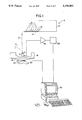
- FIG. 1 is a schematic view of the fuel particle acoustic inspection system in accordance with the present invention.
- FIG. 2 is an illustration of an unflawed and flawed particle response.
- the present invention resides in an apparatus and method for determining the integrity of the coating of nuclear fuel particles via acoustic characterization. 100% inspection capability is achieved with the present invention for millions of coated nuclear fuel particles associated with particle bed reactors as is well known in that art.
- Fuel particles (2) from a particle supply means (4) are individually dropped, as depicted by the dashed line A (with the dropped particle also being depicted in dashed line form), onto the face (6) of a transducer (8) such as a piezoelectric acoustic transducer.
- a transducer (8) such as a piezoelectric acoustic transducer.
- the particle supply means (4) is any suitable device for dropping particles individually on transducer (8).
- one example may include a hopper (10) with an opening (12) which allows a single particle to roll down a chute (14) where it drops on the transducer (8).
- other suitable particle supply means (4) only need to drop particles from a supply individually on the transducer (8).
- a compressional impulse is generated at the point of contact of the particle (2) and the transducer face (6).
- a compressional impulse wave propagates diametrically through the fuel particle which is spherical and is reflected at the opposite surface as a tensile impulse wave.
- the tensile impulse wave then makes a return journey through the spherical nuclear fuel particle with the particle snapping away from the transducer when the impulse reaches the starting point of contact between the particle (2) and the transducer face (6).
- This entire process takes only a fraction of a microsecond.
- the dropped particle (2) is then collected in another basket or hopper (16) with means for separating flawed from unflawed particles.
- FIG. 1 illustrates one example including a hopper (16) with a slanted portion (18) to collect the dropped particles.
- Channels (20, 22) connected to hopper (16) allow for separation of the flawed particles through channel (22) while the unflawed particles pass through channel (20).
- Gate (24) selectively controls the opening of the channels (20, 22) where they are disposed of or collected in a known manner. Gate (24) may be connected to the control system or a computer (30) for automatic operation. Any suitable separating means may be employed with the present invention and this example is not intended to limit the invention hereto.
- transducer (8) During the period of intimate contact between the fuel particle (2) and the transducer face (6), part of the vibrational resonance of the particle is redistributed as elastic waves in the transducer face (6) and convolved with the transducer (8) response itself.
- the resulting signal is thus a combination of transducer (8) response and the signal derived from the particle (2).
- the signal from transducer (8) is amplified with amplifier (26) and sent to an analog-to-digital (A/D) converter (28) prior to being input into a computer (30) housing digital analysis software. Differences in the signal response as depicted in FIG. 2 as viewed from the computer enable discrimination between flawed and unflawed particles.
- the "good" particle response as shown in FIG. 2 as "uncracked” preferably is a calibrated standard signal which is the basis for the comparison. In an alternate embodiment, this calibration may be performed with stored data points so that a visual inspection is not necessary. The sample to be tested generates a curve with data points that are compared to the preset values.
- a cracked fuel particle i.e., outer layer of zirconium carbide (ZrC) cracked
- ZrC zirconium carbide
- the acoustic discrimination technique of the present invention is able to discriminate flawed from unflawed fuel particles.
- any variation of particle integrity e.g., laminations, cracks, nonsphericity can give rise to subtley different signal signatures. Consequently, the system is trained to globally inspect the particle and look for any variations in the signal to allow for a general inspection technique. Once calibrated for a known acceptable particle, the system is used to screen out any particle that gives a signal response that fails to fit the "good" pattern.
Abstract
Description
Claims (5)
Priority Applications (1)
| Application Number | Priority Date | Filing Date | Title |
|---|---|---|---|
| US07/761,204 US5156802A (en) | 1991-03-15 | 1991-09-17 | Inspection of fuel particles with acoustics |
Applications Claiming Priority (2)
| Application Number | Priority Date | Filing Date | Title |
|---|---|---|---|
| US66982691A | 1991-03-15 | 1991-03-15 | |
| US07/761,204 US5156802A (en) | 1991-03-15 | 1991-09-17 | Inspection of fuel particles with acoustics |
Related Parent Applications (1)
| Application Number | Title | Priority Date | Filing Date |
|---|---|---|---|
| US66982691A Division | 1991-03-15 | 1991-03-15 |
Publications (1)
| Publication Number | Publication Date |
|---|---|
| US5156802A true US5156802A (en) | 1992-10-20 |
Family
ID=27100202
Family Applications (1)
| Application Number | Title | Priority Date | Filing Date |
|---|---|---|---|
| US07/761,204 Expired - Fee Related US5156802A (en) | 1991-03-15 | 1991-09-17 | Inspection of fuel particles with acoustics |
Country Status (1)
| Country | Link |
|---|---|
| US (1) | US5156802A (en) |
Cited By (4)
| Publication number | Priority date | Publication date | Assignee | Title |
|---|---|---|---|---|
| US5633468A (en) * | 1995-09-13 | 1997-05-27 | The Babcock & Wilcox Company | Monitoring of fuel particle coating cracking |
| GB2377019A (en) * | 2001-04-10 | 2002-12-31 | Harpley Engineering Ltd | Classification of objects by their impact characteristics upon an element |
| EP1124125A3 (en) * | 2000-01-10 | 2003-10-22 | Max-Planck-Gesellschaft zur Förderung der Wissenschaften e.V. | Process and device for acoustic detection of microparticles |
| CN115683959A (en) * | 2022-11-03 | 2023-02-03 | 北京信息科技大学 | Biomass power generation fuel particle size identification system and method based on collision sound characteristics |
Citations (18)
| Publication number | Priority date | Publication date | Assignee | Title |
|---|---|---|---|---|
| US2393225A (en) * | 1942-10-23 | 1946-01-22 | C E Hovey | Flaw detecting method |
| US3127016A (en) * | 1964-03-31 | baigent | ||
| DE2506212A1 (en) * | 1974-02-15 | 1975-08-21 | Etel Sa | METHOD AND DEVICE FOR DIFFERENTIATING THE BODIES OF A PILE |
| US4147620A (en) * | 1977-06-15 | 1979-04-03 | Black Clawson Inc. | Method and apparatus for sorting contaminant material from processing material |
| US4149075A (en) * | 1975-11-28 | 1979-04-10 | Agence Nationale De Valorisation De La Recherche (Anvar) | Methods and devices for detecting hard radiation |
| US4212398A (en) * | 1978-08-16 | 1980-07-15 | Pet Incorporated | Particle separating device |
| US4227081A (en) * | 1979-06-13 | 1980-10-07 | The United States Of America As Represented By The United States Department Of Energy | Method of evaluating the integrity of the outer carbon layer of triso-coated reactor fuel particles |
| US4466543A (en) * | 1980-10-02 | 1984-08-21 | Bystronic Maschinen Ag | Method and device for distinguishing between field crops, particularly potatoes on one hand and stones or clods of soil on the other hand |
| US4608869A (en) * | 1982-08-20 | 1986-09-02 | Trustees Of Boston University | Single particle detection system |
| US4620445A (en) * | 1984-10-19 | 1986-11-04 | Westinghouse Electric Corp. | Portable acoustic intensity measuring device |
| US4620716A (en) * | 1984-03-05 | 1986-11-04 | Luigi Carbone | Boat guide roller assembly |
| US4633714A (en) * | 1985-08-13 | 1987-01-06 | University Of Arkansas | Aerosol particle charge and size analyzer |
| US4665760A (en) * | 1986-02-12 | 1987-05-19 | Combustion Engineering, Inc. | Mounting and traversing assembly for in situ particle size measuring device |
| US4890920A (en) * | 1986-02-12 | 1990-01-02 | Combustion Engineering, Inc. | In situ particle size measuring device |
| US4894201A (en) * | 1988-05-27 | 1990-01-16 | Westinghouse Electric Corp. | Nuclear fuel pellet surface defect inspection apparatus |
| FR2635993A1 (en) * | 1988-09-07 | 1990-03-09 | Ifremer | Method and device for sorting employing the study of sounds, applied to the field of cultivating fish |
| US4944185A (en) * | 1989-01-17 | 1990-07-31 | Westinghouse Electric Corp. | System and method for qualitatively and nondestructively inspecting adhesive joints and other materials |
| US5046362A (en) * | 1988-04-26 | 1991-09-10 | Ford New Holland, Inc. | Grain loss monitors for harvesting machines |
-
1991
- 1991-09-17 US US07/761,204 patent/US5156802A/en not_active Expired - Fee Related
Patent Citations (18)
| Publication number | Priority date | Publication date | Assignee | Title |
|---|---|---|---|---|
| US3127016A (en) * | 1964-03-31 | baigent | ||
| US2393225A (en) * | 1942-10-23 | 1946-01-22 | C E Hovey | Flaw detecting method |
| DE2506212A1 (en) * | 1974-02-15 | 1975-08-21 | Etel Sa | METHOD AND DEVICE FOR DIFFERENTIATING THE BODIES OF A PILE |
| US4149075A (en) * | 1975-11-28 | 1979-04-10 | Agence Nationale De Valorisation De La Recherche (Anvar) | Methods and devices for detecting hard radiation |
| US4147620A (en) * | 1977-06-15 | 1979-04-03 | Black Clawson Inc. | Method and apparatus for sorting contaminant material from processing material |
| US4212398A (en) * | 1978-08-16 | 1980-07-15 | Pet Incorporated | Particle separating device |
| US4227081A (en) * | 1979-06-13 | 1980-10-07 | The United States Of America As Represented By The United States Department Of Energy | Method of evaluating the integrity of the outer carbon layer of triso-coated reactor fuel particles |
| US4466543A (en) * | 1980-10-02 | 1984-08-21 | Bystronic Maschinen Ag | Method and device for distinguishing between field crops, particularly potatoes on one hand and stones or clods of soil on the other hand |
| US4608869A (en) * | 1982-08-20 | 1986-09-02 | Trustees Of Boston University | Single particle detection system |
| US4620716A (en) * | 1984-03-05 | 1986-11-04 | Luigi Carbone | Boat guide roller assembly |
| US4620445A (en) * | 1984-10-19 | 1986-11-04 | Westinghouse Electric Corp. | Portable acoustic intensity measuring device |
| US4633714A (en) * | 1985-08-13 | 1987-01-06 | University Of Arkansas | Aerosol particle charge and size analyzer |
| US4665760A (en) * | 1986-02-12 | 1987-05-19 | Combustion Engineering, Inc. | Mounting and traversing assembly for in situ particle size measuring device |
| US4890920A (en) * | 1986-02-12 | 1990-01-02 | Combustion Engineering, Inc. | In situ particle size measuring device |
| US5046362A (en) * | 1988-04-26 | 1991-09-10 | Ford New Holland, Inc. | Grain loss monitors for harvesting machines |
| US4894201A (en) * | 1988-05-27 | 1990-01-16 | Westinghouse Electric Corp. | Nuclear fuel pellet surface defect inspection apparatus |
| FR2635993A1 (en) * | 1988-09-07 | 1990-03-09 | Ifremer | Method and device for sorting employing the study of sounds, applied to the field of cultivating fish |
| US4944185A (en) * | 1989-01-17 | 1990-07-31 | Westinghouse Electric Corp. | System and method for qualitatively and nondestructively inspecting adhesive joints and other materials |
Non-Patent Citations (2)
| Title |
|---|
| Battle, D. J., Scruby, C. B., "Characterization of Particle Impact by Quantitative Acoustic Emission", Wear, vol. 137, pp. 63-90, 1990. |
| Battle, D. J., Scruby, C. B., Characterization of Particle Impact by Quantitative Acoustic Emission , Wear, vol. 137, pp. 63 90, 1990. * |
Cited By (5)
| Publication number | Priority date | Publication date | Assignee | Title |
|---|---|---|---|---|
| US5633468A (en) * | 1995-09-13 | 1997-05-27 | The Babcock & Wilcox Company | Monitoring of fuel particle coating cracking |
| EP1124125A3 (en) * | 2000-01-10 | 2003-10-22 | Max-Planck-Gesellschaft zur Förderung der Wissenschaften e.V. | Process and device for acoustic detection of microparticles |
| GB2377019A (en) * | 2001-04-10 | 2002-12-31 | Harpley Engineering Ltd | Classification of objects by their impact characteristics upon an element |
| GB2377019B (en) * | 2001-04-10 | 2005-07-06 | Harpley Engineering Ltd | Classification of objects |
| CN115683959A (en) * | 2022-11-03 | 2023-02-03 | 北京信息科技大学 | Biomass power generation fuel particle size identification system and method based on collision sound characteristics |
Similar Documents
| Publication | Publication Date | Title |
|---|---|---|
| EP0655623B1 (en) | Relative resonant frequency shifts to detect cracks | |
| US5929315A (en) | Measuring crack growth by acoustic emission | |
| US6173613B1 (en) | Measuring crack growth by acoustic emission | |
| US5408880A (en) | Ultrasonic differential measurement | |
| KR20100110340A (en) | Non-destructive testing, in particular for tubes during manufacture or in the finished state | |
| US8185327B2 (en) | Monitoring of composite materials | |
| SE518997C2 (en) | Method and apparatus for detecting damage in materials or articles | |
| US4738137A (en) | Acoustic emission frequency discrimination | |
| JPH0237542B2 (en) | ||
| US7231304B2 (en) | Interference pattern testing of materials | |
| Ohtsu et al. | Principles of the acoustic emission (AE) method and signal processing | |
| US5156802A (en) | Inspection of fuel particles with acoustics | |
| US3453871A (en) | Method and apparatus for detecting flaws in materials | |
| Rao | Acoustic emission and signal analysis | |
| US5633468A (en) | Monitoring of fuel particle coating cracking | |
| Woodward et al. | The use of signal analysis to identify sources of acoustic emission | |
| de Almeida | Neural network detection of fatigue crack growth in riveted joints using acoustic emission | |
| JP3764233B2 (en) | Abnormality inspection method and apparatus | |
| Smith Jr | Acoustic emission from spectrum fatigue cracks in 7075 aluminum | |
| Legendre et al. | Ultrasonic aluminum weld testing method based on the wavelet transform and a neural classifier | |
| Scala | A semi-adaptive approach to in-flight monitoring using acoustic emission | |
| Kouvarakos | Isolating failure mechanisms in a fiberglass/epoxy tensile test specimen using acoustic emission signal parameters | |
| Woodward et al. | Flaw identification using acoustic emission | |
| JPS5860253A (en) | Ultrasonic flaw detector | |
| JP3283430B2 (en) | Ultrasonic inspection device and inspection data management system for the ultrasonic probe |
Legal Events
| Date | Code | Title | Description |
|---|---|---|---|
| FEPP | Fee payment procedure |
Free format text: PAYOR NUMBER ASSIGNED (ORIGINAL EVENT CODE: ASPN); ENTITY STATUS OF PATENT OWNER: LARGE ENTITY |
|
| REMI | Maintenance fee reminder mailed | ||
| FPAY | Fee payment |
Year of fee payment: 4 |
|
| SULP | Surcharge for late payment | ||
| AS | Assignment |
Owner name: BWX TECHNOLOGIES, INC., VIRGINIA Free format text: ASSIGNMENT OF ASSIGNORS INTEREST;ASSIGNOR:BABCOCK & WILCOX COMPANY, THE;REEL/FRAME:008829/0402 Effective date: 19970630 |
|
| FPAY | Fee payment |
Year of fee payment: 8 |
|
| REMI | Maintenance fee reminder mailed | ||
| LAPS | Lapse for failure to pay maintenance fees | ||
| STCH | Information on status: patent discontinuation |
Free format text: PATENT EXPIRED DUE TO NONPAYMENT OF MAINTENANCE FEES UNDER 37 CFR 1.362 |
|
| FP | Lapsed due to failure to pay maintenance fee |
Effective date: 20041020 |