US5156223A - Fluid operated vibratory jar with rotating bit - Google Patents
Fluid operated vibratory jar with rotating bit Download PDFInfo
- Publication number
- US5156223A US5156223A US07/699,921 US69992191A US5156223A US 5156223 A US5156223 A US 5156223A US 69992191 A US69992191 A US 69992191A US 5156223 A US5156223 A US 5156223A
- Authority
- US
- United States
- Prior art keywords
- stem
- tool body
- tool
- working member
- bit
- Prior art date
- Legal status (The legal status is an assumption and is not a legal conclusion. Google has not performed a legal analysis and makes no representation as to the accuracy of the status listed.)
- Expired - Lifetime
Links
Images


Classifications
-
- E—FIXED CONSTRUCTIONS
- E21—EARTH DRILLING; MINING
- E21B—EARTH DRILLING, e.g. DEEP DRILLING; OBTAINING OIL, GAS, WATER, SOLUBLE OR MELTABLE MATERIALS OR A SLURRY OF MINERALS FROM WELLS
- E21B31/00—Fishing for or freeing objects in boreholes or wells
- E21B31/107—Fishing for or freeing objects in boreholes or wells using impact means for releasing stuck parts, e.g. jars
- E21B31/113—Fishing for or freeing objects in boreholes or wells using impact means for releasing stuck parts, e.g. jars hydraulically-operated
-
- E—FIXED CONSTRUCTIONS
- E21—EARTH DRILLING; MINING
- E21B—EARTH DRILLING, e.g. DEEP DRILLING; OBTAINING OIL, GAS, WATER, SOLUBLE OR MELTABLE MATERIALS OR A SLURRY OF MINERALS FROM WELLS
- E21B17/00—Drilling rods or pipes; Flexible drill strings; Kellies; Drill collars; Sucker rods; Cables; Casings; Tubings
- E21B17/02—Couplings; joints
- E21B17/04—Couplings; joints between rod or the like and bit or between rod and rod or the like
- E21B17/07—Telescoping joints for varying drill string lengths; Shock absorbers
- E21B17/073—Telescoping joints for varying drill string lengths; Shock absorbers with axial rotation
-
- E—FIXED CONSTRUCTIONS
- E21—EARTH DRILLING; MINING
- E21B—EARTH DRILLING, e.g. DEEP DRILLING; OBTAINING OIL, GAS, WATER, SOLUBLE OR MELTABLE MATERIALS OR A SLURRY OF MINERALS FROM WELLS
- E21B4/00—Drives for drilling, used in the borehole
- E21B4/06—Down-hole impacting means, e.g. hammers
- E21B4/14—Fluid operated hammers
-
- E—FIXED CONSTRUCTIONS
- E21—EARTH DRILLING; MINING
- E21B—EARTH DRILLING, e.g. DEEP DRILLING; OBTAINING OIL, GAS, WATER, SOLUBLE OR MELTABLE MATERIALS OR A SLURRY OF MINERALS FROM WELLS
- E21B4/00—Drives for drilling, used in the borehole
- E21B4/16—Plural down-hole drives, e.g. for combined percussion and rotary drilling; Drives for multi-bit drilling units
Definitions
- the present invention relates generally to downhole oil well tools run on a pipe string, including impact or jarring type downhole oil well tools, and more particularly, to a fluid operated jarring tool and related methods of operation for use in well bores and wherein the tool has a bit or working end that jars downwardly and rotates when the bit is not subject to weight of the pipe string in order to prevent imprinting on the drilling surface.
- the tool of my prior U.S. Pat. No. 3,946,819 generally includes a housing with a tubular stem member telescopically received in the housing for relative reciprocal movement between a first terminal position and a second terminal position in response to fluid pressure in the housing.
- the lower portion of the housing is formed to define a downwardly facing hammer and the stem member includes an upwardly facing anvil which is positioned to be struck by the hammer.
- the tool includes a valve assembly that is responsive to predetermined movement of the stem member toward the second terminal position to relieve fluid pressure and permit the stem member to return to the first terminal position.
- a valve assembly that is responsive to predetermined movement of the stem member toward the second terminal position to relieve fluid pressure and permit the stem member to return to the first terminal position.
- U.S. Pat. No. 4,462,471 there is disclosed a jarring or drilling mechanism that may be adapted to provide upward and downward blows.
- the mechanism of the '471 patent includes a housing having opposed axially spaced apart hammer surfaces slidingly mounted within the housing between the anvil surfaces.
- a spring is provided for urging the hammer upwardly.
- the mechanism of the '471 patent operates by fluid pressure acting on the valve and hammer to urge the valve and hammer axially downwardly until the downward movement of the valve is stopped, preferably by the full compression of the valve spring.
- the seal between the valve and the hammer is broken and the valve moves axially upwardly.
- the direction jarring of the mechanism of the '471 patent is determined by the relationship between the fluid pressure and the strength of the spring that urges the hammer upwardly.
- the mechanism is adapted for upward jarring.
- the valve opens, the hammer moves upwardly to strike the downwardly facing anvil surface of the housing.
- the mechanism can be made to deliver a downward and upward blow by increasing the fluid pressure and decreasing the strength of the spring that urges the hammer upwardly.
- the downward momentum of the hammer is increased such that the hammer strikes the upwardly facing anvil of the housing prior to being urged upwardly to strike the downwardly facing anvil surface.
- the present invention rotates the working end, e.g. a drill bit, during impact drilling.
- a drill bit By rotating the bit when it is not subject to weight of the pipe string, very little energy is required. As compared to rotating the bit when it is weighted, this "unweighted" rotation slows bit wear.
- impact drilling can proceed with a constant movement or rotation of the bit to prevent imprinting on the drilling surface.
- drill pipe weight is the typical method of controlling the weight on a drill bit.
- a coiled spring, disk spring or other bias means is placed in the tool in such a way that a predetermined amount of force or load could be applied to the bit. This force will vary some what, increasing as the tool body moves downward.
- two forces of downward force can be applied to the bit. The first would be the weight of the tubing on the tool, controlled by the operator at the surface of the well, and the second would be the predetermined constant load imposed on the bit through the "bias means", preferably a coil spring or disk spring.
- Impact tools operate on a fixed volume of fluid per stroke, the higher the volume the faster the impact cycle.
- the impact cycle of these tools depends on the near total evacuation of the pressure in the chamber to obtain a clean blow. There is therefore a point where the amount of fluid being pumped through a tool exceeds the tool's ability to exhaust the chamber (volumetric efficiency). When this point is reached, the tool chamber will maintain a positive pressure differential and the impact will be cushioned much like the action of an automobile shock absorber. This condition is especially prevalent when a highly expansive gas such as nitrogen enters the chamber. It is therefore advantageous and desirable to devise a method that will allow one to maintain a high fluid volume while at the same time allowing the impact tool to perform at an optimum rate.
- choke holes can be sized to pass as much fluid as desired and yet maintain the optimum fluid value for the tool's operation.
- the fluid volume must exceed the flow capability of the chokes before the chamber of the tool can pressure to the point of tool operation. For example, if it is established that a given tool's optimum operating fluid rate is 30 gpm but 60 gpm is required for lifting, then the choke would be designed to pass 30 gpm at the tool's optimum operating pressure. All fluid exits the tool via the center bore and out the bottom, aiding the lifting operation.
- the present invention provides an improved well tool and method of operation for use with an elongated pipe string that can load the tool transmitting impact to the tool and to the adjacent drill string.
- the tool includes a housing connectable to and in fluid communication with the lower end of a pipe string, and defining at least one fluid chamber therein.
- a tubular stem having a flow channel therethrough is telescopically received by the housing for relative reciprocal movement and sealing engagement therewith between a first "pressured up" unloaded and a second "impact" loaded position.
- An impact receptive working member is attached to one end of the stem for relative movement therewith between the first and second positions, wherein impact is transmitted to the working member in the second impact position.
- the working member can be a drill bit, or a bulb shaped or "light bulb” bit.
- a valve carried by the housing is operable by fluid pressure transmitted by the pipe string, and responsive to a predetermined movement of the stem with respect to the housing relieves fluid pressure in the tool housing permitting return of the stem and the housing to the first "pressure up" position.
- Biasing springs disposed in the chamber bias the stem member and the housing toward the first position and bias the valve means into a closed position when the stem member and the housing are in the first "pressure up” position.
- An interface between the housing and the stem rotate the working member during relative movement of the housing and the stem.
- the interface includes a clutch assembly for rotating the working member in one rotational direction and for preventing rotation of the working member in the opposite rotational direction.
- the interface comprises a clutch assembly with a sleeve positioned concentrically between the housing and the stem for rotating the working member when the housing and stem move relative to one another.
- the clutch assembly includes a tubular member having one or more spiralling and longitudinally extending slots and the slots define a track, and a corresponding number of pins (or a roller bearing mechanism) connects the housing and tubular stem together.
- the interface rotates the working member at least partially when the working member is unloaded.
- the working member is rotated prior to loading of the working member with the pipe string.
- the tubular stem is contained within the housing and the interface sleeve is positioned concentrically between the housing and the stem.
- the interface includes a tubular member having an enlarged lower end that engages the housing upon impact transmitted to the bit.
- the valving means includes a tubular valve element having a fluid port therethrough, one end portion communicating with the fluid chamber and the other end portion positioned to form a fluid seal with the tubular stem for stopping fluid flow therethrough to the working member.
- the tubular stem is an elongated generally cylindrical stem with a central stem flow bore or channel therethrough and the flow bore or channel is in fluid communication with the working member.
- laterally extending "choke" holes are provided for adjusting the fluid volume so that the tool's optimum operating fluid rate is not exceed when operating in a well wherein large volumes of fluid or highly expansive gas such as nitrogen enters the chamber.
- a minimum operating pressure is built into the tool so that the tool will function in formations wherein it does not meet substantial resistance.
- a bias means (preferably coil or disk spring) is used to control the amount of weight on the drill bit.
- FIG. 1 is a sectional elevational view of the preferred embodiment of the apparatus of the present invention during impact;
- FIG. 2 is a sectional elevational view of the preferred embodiment of the apparatus of the present invention illustrating the tool in a position with the bit in a loaded position;
- FIG. 3 is a sectional elevational view of the preferred embodiment of the apparatus of the present invention illustrating the bit in an unloaded position with the valve opened;
- FIG. 4 is a sectional elevational view of the preferred embodiment of the apparatus of the present invention in the impact position with the valve opened;
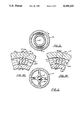
- FIG. 5 is a sectional view taken along lines 5--5 of FIG. 4;
- FIGS. 5A-5B are fragmentary views illustrating the locking cam portion of the clutch member
- FIG. 6 is a sectional view taken along lines 6--6 of FIG. 4;
- FIG. 7 is an elevational view of a light bulb type bit working member as used with the preferred embodiment of the apparatus of the present invention and its method of operation.
- FIG. 8 is a sectional, elevational view of an alternate embodiment of the apparatus of the present invention.
- FIG. 9 is an elevational view of an alternate embodiment of the apparatus of the present invention shown in an extended position
- FIG. 10 is a sectional, elevational, schematic view illustrating the use of the method and apparatus of the present invention showing horizontal well drilling.
- FIG. 10A is another sectional view illustrating the method and apparatus of the present invention as used in horizontal well drilling.
- FIGS. 1-4 illustrate the preferred embodiment of the apparatus of the present invention designated generally by the numeral 10.
- FIGS. 1-4 there can be seen sequential sectional elevational views showing operation of the tool beginning with the post impact position (immediately prior to pressuring up) that is shown in FIG. 1 and ending with the tool impact position shown in FIG. 4.
- the apparatus 10 includes a housing 11 having upper 11A and lower 11B end portions.
- the housing provides at upper end portion 11A, a longitudinally extending port 12.
- the upper end portion 11A of the tool body 11 can be attached for example to a running and pulling sub (not shown) which is then attached to a pipe string such as, for example, a coil tubing unit.
- a running and pulling sub not shown
- the connection of the tool 10 to a coil tubing unit using a running and pulling sub is described generally in my prior U.S. Pat. Nos. 3,946,819 and 4,462,471 which are incorporated herein by reference.
- the lower end portion 11B of the tool body 11 carries a working member such as drill bit 14.
- a central tubular section 13 of housing 11 with an annular wall 15 defines an internal fluid chamber 16.
- Chamber 16 communicates with port 12 at 17 so that fluid transmitted to the tool 11 through the pipe string of the coil tubing unit can be used to "pressure up" the tool by conveying pressurized fluid to the tool chamber 16 via port 12.
- Fluid chamber 16 carries valving member 20, a longitudinally extending valve member having a generally X-shaped cross section such as the valving member shown in FIG. 6 of my prior U.S. Pat. No. 3,946,819.
- Valve member 20 includes an upper 21 and lower 22 end portions. Lower end portion 22 can form a fluid tight seal at seat 23 with the upper end portion 26 of tubular stem 25. Coil spring 24 biases valving member 20 upwardly when the seal at seat 23 between lower end portion 22 of valve 20 and the upper end portion 26 of stem 25 is broken. Thus, 23 defines a valve seat for sealing the longitudinal flow bore 27 of stem 25.
- the lower most end portion 28 of stem 25 carries working member 14, such as a drill bit.
- the central longitudinal stem flow bore 27 thus extends the full length of stem 25 communicating with the bore 29 of working member 14.
- flow can also communicate with and flow through bore 29 of working member 14, exiting the bit or working member 14, carrying away cuttings generated during drilling or like operations.
- the position of the tool 10 in FIG. 1 illustrates the impact position in that the housing 11 rests upon the bit 14 with the annular shoulder 11C of housing 11 resting upon the annular shoulder 32 of clutch 35.
- clutch member 35 allows rotation in one direction only, clockwise rotation of bit 14 in this case during operation as viewed from the top view. This rotation also tightens all threaded connections of the tool apparatus 10.
- FIG. 2 a "pressured up” position is shown. Fluid under pressure is entering chamber 16 via port 12 (see arrows 40, FIG. 2) and forces housing 11 to rise with respect to stem 25 and bit 14.
- port 12 see arrows 40, FIG. 2
- member 35 is unloaded and the clutch allows the member 35 to rotate counter-clockwise around stem member 25, by means of the helix slots 50 and the pins 60.
- Diagonal or helical slot 50 of clutch sleeve 35A has rotated upon pin 60 which is connected to the tubular section 13 of housing 11 and more particularly extends from the annular wall 15 portion thereof.
- the pressurized fluid contained in chamber 16 exits the tool 10 via stem longitudinal bore 27 and the bore 29 of working member 14. This exiting of pressurized fluid helps clean cuttings away from the drilling area.
- Clutch 35 is a single rotation directional clutch which only allows single direction rotation of the bit 14.
- Clutch 35 (FIG. 5) uses a plurality of small closely spaced cam members C. Such unidirectional clutch cam members C are commercially available.
- the cams C have flat upper and lower surfaces, and fit within recess 35A.
- Each cam C has a radially extending vertical surface 71 that is larger than its opposed vertical radial surface 70.
- Each cam has a smaller inner curved vertical surface 72 and a larger outer curved vertical surface 73.
- the outer curved surface thus has a locking tip 74 which binds against surface recess 35A when rotation is in one direction. However when rotation is in the opposite direction, the locking tip 74 rotates toward stem 25 so that binding is stopped and rotation permitted.
- a feature of the present invention is that rotation of the bit thus takes place prior to loading of the bit with the housing and the pipe string. Notice in FIG. 3 that as the pin 60 moves downwardly through spiralling slot 50, rotation of the bit takes place. It is not until the lower annular shoulder 11C of housing 11 strikes the upper annular shoulder 32 of clutch 35 that the impact is transmitted from the housing 11 and the pipe string directly to the working member 14 (see FIG. 4).
- This second spring 24A is placed between the enlarged upper end 26 of stem 25 and shoulder 24B.
- a second coil spring 24A can be placed between the enlarged upper end 26 of stem 25 and shoulder 24C, to serve as the bias means for controlling load on the drill bit 14.
- FIG. 7 a light bulb bit 80 is shown attached to apparatus 10 which is affixed to the lower end of a coil tubing spring, CT.
- the light bulb bit 80 could be used, for example, as the working member when the method of the present invention is for acidizing. Using the rotation and reciprocation of the apparatus 10 of the present invention together with a working member such as light bulb bit 80, acidizing, for example a well can be accomplished.
- the apparatus 10 is equipped with a plurality of diagonally extending choke holes 81, 82 which are installed diagonally exiting the impact tool apparatus 10 bore 27.
- the choke holes 81, 82 can be sized to pass as much fluid as desired from the bore 27 but yet maintain optimum fluid value for the apparatus 10 operation.
- the fluid volume must exceed the flow capability of the chokes 81, 82 before the bore 27 can pressure to the point of operation. For example, if it is established that a given optimum operating rate is 30 gpm, but 60 gpm is required for lifting, then the choke would be designed to pass 30 gpm at the optimum operating pressure. All fluids exit the tool via bore 27 and out the bottom, aiding in the lifting operation.
- FIGS. 8 and 9 provide a second coil spring 24A that can be of a desired spring value to preload the tool with a minimum operating pressure.
- the working member 14 such as a drill bit
- the rapid reciprocation of the tool produces a vibratory effect on both the tool body and the attached drill string.
- the pressuring up of the tube causes the tube to expand and therefore straighten. Releasing the pressure causes the tube to relax and spring back. This utilizes the natural spring action of the tube to create vibration.
- the magnitude of the vibration can be intensified by adding a weighted bar between the working bit and the impact surfaces of the tool.
- the rate (volume) of the fluids being pumped can be controlled at the surface until the most advantageous vibration frequencies are achieved.
- This vibration can be utilized when penetration begins, and before the tubing begins going into an "S" shaped configuration, the vibration thus shaking the coil tubing and forcing it to remain “laid-out” or in a more relaxed, straighter configuration thus resulting in deeper penetration of the drilling.
- the present invention provides a constant running, vibrating impact variable frequency apparatus that can be installed at the bottom of the drill string, coil tubing, or the like. It is possible also to install the apparatus 10 of the present invention at various intervals in the coil tubing to provide continuous vibration at desired positions along the work string.
- a coil tubing unit (CTU) is designated in schematic form and a horizontal well bore HB wherein the coil tubing CT can be seen in a curved orientation within the well bore HB.
- the apparatus 10 of the present invention is shown installed at the end of the coiled tubing CT and within the horizontal bore HB so that the apparatus 10 of the present invention induces a vibration into the attached coil tubing which helps maintain the coil tubing (CT) in a straightened configuration as shown in FIG. 10A.
Abstract
Description
Claims (7)
Priority Applications (1)
| Application Number | Priority Date | Filing Date | Title |
|---|---|---|---|
| US07/699,921 US5156223A (en) | 1989-06-16 | 1991-05-14 | Fluid operated vibratory jar with rotating bit |
Applications Claiming Priority (3)
| Application Number | Priority Date | Filing Date | Title |
|---|---|---|---|
| US07/367,341 US4958691A (en) | 1989-06-16 | 1989-06-16 | Fluid operated vibratory jar with rotating bit |
| US58799390A | 1990-09-25 | 1990-09-25 | |
| US07/699,921 US5156223A (en) | 1989-06-16 | 1991-05-14 | Fluid operated vibratory jar with rotating bit |
Related Parent Applications (1)
| Application Number | Title | Priority Date | Filing Date |
|---|---|---|---|
| US58799390A Continuation-In-Part | 1989-06-16 | 1990-09-25 |
Publications (1)
| Publication Number | Publication Date |
|---|---|
| US5156223A true US5156223A (en) | 1992-10-20 |
Family
ID=27408810
Family Applications (1)
| Application Number | Title | Priority Date | Filing Date |
|---|---|---|---|
| US07/699,921 Expired - Lifetime US5156223A (en) | 1989-06-16 | 1991-05-14 | Fluid operated vibratory jar with rotating bit |
Country Status (1)
| Country | Link |
|---|---|
| US (1) | US5156223A (en) |
Cited By (76)
| Publication number | Priority date | Publication date | Assignee | Title |
|---|---|---|---|---|
| US5316094A (en) * | 1992-10-20 | 1994-05-31 | Camco International Inc. | Well orienting tool and/or thruster |
| US5322136A (en) * | 1992-07-17 | 1994-06-21 | Smith International, Inc. | Air percussion drilling assembly |
| US5372196A (en) * | 1992-07-07 | 1994-12-13 | Atlas Copco Rocktech Ab | Hammer drill device |
| US5373898A (en) * | 1992-10-20 | 1994-12-20 | Camco International Inc. | Rotary piston well tool |
| US5662180A (en) * | 1995-10-17 | 1997-09-02 | Dresser-Rand Company | Percussion drill assembly |
| US5669457A (en) * | 1996-01-02 | 1997-09-23 | Dailey Petroleum Services Corp. | Drill string orienting tool |
| US5673764A (en) * | 1995-04-14 | 1997-10-07 | Falgout, Sr.; Thomas E. | Drill string orienting motor |
| US5775444A (en) * | 1996-10-23 | 1998-07-07 | Falgout, Sr.; Thomas E. | Drill string orienting motor |
| USRE36166E (en) * | 1992-07-17 | 1999-03-30 | Smith International, Inc. | Air percussion drilling assembly for directional drilling applications |
| US5944100A (en) * | 1997-07-25 | 1999-08-31 | Baker Hughes Incorporated | Junk bailer apparatus for use in retrieving debris from a well bore of an oil and gas well |
| US5957220A (en) * | 1995-10-17 | 1999-09-28 | Dresser-Rand Company | Percussion drill assembly |
| US6035954A (en) * | 1998-02-12 | 2000-03-14 | Baker Hughes Incorporated | Fluid operated vibratory oil well drilling tool with anti-chatter switch |
| US6050346A (en) * | 1998-02-12 | 2000-04-18 | Baker Hughes Incorporated | High torque, low speed mud motor for use in drilling oil and gas wells |
| US6062324A (en) * | 1998-02-12 | 2000-05-16 | Baker Hughes Incorporated | Fluid operated vibratory oil well drilling tool |
| USRE36848E (en) * | 1992-07-17 | 2000-09-05 | Smith International, Inc. | Air percussion drilling assembly |
| US6182775B1 (en) | 1998-06-10 | 2001-02-06 | Baker Hughes Incorporated | Downhole jar apparatus for use in oil and gas wells |
| US6206101B1 (en) | 1996-06-07 | 2001-03-27 | Bakke Technology As | Method and device for facilitating the insertion of a coiled tube into a well and for loosening stuck objects in a well |
| US20010047866A1 (en) * | 1998-12-07 | 2001-12-06 | Cook Robert Lance | Wellbore casing |
| US6338390B1 (en) | 1999-01-12 | 2002-01-15 | Baker Hughes Incorporated | Method and apparatus for drilling a subterranean formation employing drill bit oscillation |
| US20020050360A1 (en) * | 1998-12-07 | 2002-05-02 | Cook Robert Lance | Forming a wellbore casing while simultaneously drilling a wellbore |
| US20020066576A1 (en) * | 1998-11-16 | 2002-06-06 | Cook Robert Lance | Isolation of subterranean zones |
| US20020074134A1 (en) * | 1999-02-26 | 2002-06-20 | Shell Oil Co. | Apparatus for actuating an annular piston |
| US20020121372A1 (en) * | 1998-11-16 | 2002-09-05 | Shell Oil Co. | Isolation of subterranean zones |
| EP1239112A2 (en) * | 2001-03-01 | 2002-09-11 | Schlumberger Technology B.V. | Method and apparatus to vibrate a downhole component |
| US20020148612A1 (en) * | 1998-11-16 | 2002-10-17 | Shell Oil Co. | Isolation of subterranean zones |
| US6474421B1 (en) * | 2000-05-31 | 2002-11-05 | Baker Hughes Incorporated | Downhole vibrator |
| WO2002095180A2 (en) * | 2001-05-19 | 2002-11-28 | Rotech Holdings Limited | Impact downhole tool |
| US6502638B1 (en) * | 1999-10-18 | 2003-01-07 | Baker Hughes Incorporated | Method for improving performance of fishing and drilling jars in deviated and extended reach well bores |
| US6575240B1 (en) | 1998-12-07 | 2003-06-10 | Shell Oil Company | System and method for driving pipe |
| US20030209351A1 (en) * | 2002-05-08 | 2003-11-13 | Taylor Jeff L. | Down hole motor |
| US20040045716A1 (en) * | 2001-01-05 | 2004-03-11 | Stig Bakke | Hydraulic jar device |
| US6712134B2 (en) * | 2002-02-12 | 2004-03-30 | Baker Hughes Incorporated | Modular bi-directional hydraulic jar with rotating capability |
| US20040069533A1 (en) * | 2000-12-02 | 2004-04-15 | Franz-Josef Puttmann | Pneumatic rock-boring device and method for starting such a device |
| US20040144566A1 (en) * | 2000-12-09 | 2004-07-29 | Fisher Hugh Edward | Boring apparatus |
| US20040159464A1 (en) * | 2003-02-19 | 2004-08-19 | Ashmin, Lc | Percussion tool and method |
| US6823937B1 (en) | 1998-12-07 | 2004-11-30 | Shell Oil Company | Wellhead |
| US20050194182A1 (en) * | 2004-03-03 | 2005-09-08 | Rodney Paul F. | Surface real-time processing of downhole data |
| US20050194183A1 (en) * | 2004-03-04 | 2005-09-08 | Gleitman Daniel D. | Providing a local response to a local condition in an oil well |
| US20050194184A1 (en) * | 2004-03-04 | 2005-09-08 | Gleitman Daniel D. | Multiple distributed pressure measurements |
| US20050194185A1 (en) * | 2004-03-04 | 2005-09-08 | Halliburton Energy Services | Multiple distributed force measurements |
| WO2005111366A1 (en) | 2004-04-29 | 2005-11-24 | Varco I/P, Inc. | A reciprocable impact hammer |
| WO2006082421A1 (en) * | 2005-02-04 | 2006-08-10 | Petrowell Limited | Apparatus and method |
| US20060207770A1 (en) * | 2005-03-17 | 2006-09-21 | Schlumberger Technology Corporation | Methods and apparatus for placement of well equipment |
| US20080127528A1 (en) * | 2006-11-30 | 2008-06-05 | Mlt Soil Co., Ltd. | Earth auger head and excavation method |
| US20080251254A1 (en) * | 2007-04-16 | 2008-10-16 | Baker Hughes Incorporated | Devices and methods for translating tubular members within a well bore |
| US20080295363A1 (en) * | 2007-05-28 | 2008-12-04 | Daewon Electric Co. Ltd. | Extendable excavating screw unit equipped with hydraulic excavating auxiliary blades |
| US20090173542A1 (en) * | 2008-01-04 | 2009-07-09 | Longyear Tm, Inc. | Vibratory unit for drilling systems |
| US7665532B2 (en) | 1998-12-07 | 2010-02-23 | Shell Oil Company | Pipeline |
| US7712522B2 (en) | 2003-09-05 | 2010-05-11 | Enventure Global Technology, Llc | Expansion cone and system |
| US7740076B2 (en) | 2002-04-12 | 2010-06-22 | Enventure Global Technology, L.L.C. | Protective sleeve for threaded connections for expandable liner hanger |
| US7739917B2 (en) | 2002-09-20 | 2010-06-22 | Enventure Global Technology, Llc | Pipe formability evaluation for expandable tubulars |
| US7775290B2 (en) | 2003-04-17 | 2010-08-17 | Enventure Global Technology, Llc | Apparatus for radially expanding and plastically deforming a tubular member |
| US7793721B2 (en) | 2003-03-11 | 2010-09-14 | Eventure Global Technology, Llc | Apparatus for radially expanding and plastically deforming a tubular member |
| US7819185B2 (en) | 2004-08-13 | 2010-10-26 | Enventure Global Technology, Llc | Expandable tubular |
| US20100276204A1 (en) * | 2009-05-01 | 2010-11-04 | Thru Tubing Solutions, Inc. | Vibrating tool |
| US20100319907A1 (en) * | 2007-02-28 | 2010-12-23 | Hallundbaek Joergen | Drilling Tool with Feed Control |
| US7886831B2 (en) | 2003-01-22 | 2011-02-15 | Enventure Global Technology, L.L.C. | Apparatus for radially expanding and plastically deforming a tubular member |
| US7918284B2 (en) | 2002-04-15 | 2011-04-05 | Enventure Global Technology, L.L.C. | Protective sleeve for threaded connections for expandable liner hanger |
| US20110139510A1 (en) * | 2009-12-16 | 2011-06-16 | Halliburton Energy Services, Inc. | Apparatus and Method for Reaming a Wellbore During the Installation of a Tubular String |
| US20110155467A1 (en) * | 2009-12-28 | 2011-06-30 | Halliburton Energy Services, Inc. | Timed impact drill bit steering |
| US20110232970A1 (en) * | 2010-03-25 | 2011-09-29 | Halliburton Energy Services, Inc. | Coiled tubing percussion drilling |
| CN102536114A (en) * | 2010-12-23 | 2012-07-04 | 中国石油大学(华东) | Mechanical underground vibration-absorption punching drilling tool |
| US8230912B1 (en) | 2009-11-13 | 2012-07-31 | Thru Tubing Solutions, Inc. | Hydraulic bidirectional jar |
| US8365818B2 (en) | 2011-03-10 | 2013-02-05 | Thru Tubing Solutions, Inc. | Jarring method and apparatus using fluid pressure to reset jar |
| CN103291214A (en) * | 2013-06-19 | 2013-09-11 | 中国石油大学(华东) | Reciprocating type hydraulic-drive impacter |
| US20130277116A1 (en) * | 2012-04-18 | 2013-10-24 | Ulterra Drilling Technologies, L.P. | Mud motor with integrated percussion tool and drill bit |
| US8657007B1 (en) | 2012-08-14 | 2014-02-25 | Thru Tubing Solutions, Inc. | Hydraulic jar with low reset force |
| US20140174779A1 (en) * | 2011-08-19 | 2014-06-26 | Pen-Rock As | High frequency fluid driven drill hammer percussion drilling in hard formations |
| US20140185972A1 (en) * | 2012-12-31 | 2014-07-03 | Smith International, Inc. | Bearing Assembly for a Drilling Tool |
| EP2526252A4 (en) * | 2010-01-22 | 2015-05-27 | Randall E Gosselin | Wellbore obstruction-clearing tool and method of use |
| CN106639864A (en) * | 2015-10-30 | 2017-05-10 | 中石化石油工程技术服务有限公司 | Vibrating impacting short piece |
| WO2017127404A1 (en) * | 2016-01-19 | 2017-07-27 | Ashmin Holding Llc | Downhole extended reach tool method |
| US10047573B2 (en) | 2013-12-23 | 2018-08-14 | Halliburton Energy Services, Inc. | In-line tortional vibration mitigation mechanism for oil well drilling assembly |
| CN108868680A (en) * | 2018-04-11 | 2018-11-23 | 中国石油天然气集团有限公司 | Continuous bumper jar |
| CN110454083A (en) * | 2019-08-21 | 2019-11-15 | 北京众英泰科能源科技有限公司 | With the circumferential power drill bit that spins |
| CN110513036A (en) * | 2019-08-21 | 2019-11-29 | 北京众英泰科能源科技有限公司 | Helicoid hydraulic motor with circumferential power of spinning |
Citations (13)
| Publication number | Priority date | Publication date | Assignee | Title |
|---|---|---|---|---|
| US1654833A (en) * | 1921-04-12 | 1928-01-03 | Fred E Tasker | Gasoline rock drill |
| US1861042A (en) * | 1930-04-28 | 1932-05-31 | John A Zublin | Rotary bit with hammering device |
| US1934252A (en) * | 1931-02-02 | 1933-11-07 | Black & Decker Mfg Co | Bit rotating device for reciprocating tools |
| US2755069A (en) * | 1955-02-18 | 1956-07-17 | Arnold M Mosby | Rotation mechanism for rock drills |
| US3815692A (en) * | 1972-10-20 | 1974-06-11 | Varley R Co Inc | Hydraulically enhanced well drilling technique |
| US3946819A (en) * | 1975-01-27 | 1976-03-30 | Brown Equipment & Service Tools, Inc. | Well tool and method of use therefor |
| US3978931A (en) * | 1975-10-30 | 1976-09-07 | Boris Vasilievich Sudnishnikov | Air-operated drilling machine or rotary-percussive action |
| US4209070A (en) * | 1975-11-14 | 1980-06-24 | Kamensky Veniamin V | Air-operated self-propelling rotary-percussive downhole drill |
| US4462471A (en) * | 1982-10-27 | 1984-07-31 | James Hipp | Bidirectional fluid operated vibratory jar |
| US4928770A (en) * | 1989-02-09 | 1990-05-29 | Baker Hughes Incorporated | Mechanical manipulation tool with hydraulic hammer |
| US4958690A (en) * | 1987-02-25 | 1990-09-25 | Salzgitter Maschinenbau Gmbh | Drilling device with hydraulic percussion generator for earth drilling purposes |
| US4958691A (en) * | 1989-06-16 | 1990-09-25 | James Hipp | Fluid operated vibratory jar with rotating bit |
| US5029642A (en) * | 1989-09-07 | 1991-07-09 | Crawford James B | Apparatus for carrying tool on coil tubing with shifting sub |
-
1991
- 1991-05-14 US US07/699,921 patent/US5156223A/en not_active Expired - Lifetime
Patent Citations (13)
| Publication number | Priority date | Publication date | Assignee | Title |
|---|---|---|---|---|
| US1654833A (en) * | 1921-04-12 | 1928-01-03 | Fred E Tasker | Gasoline rock drill |
| US1861042A (en) * | 1930-04-28 | 1932-05-31 | John A Zublin | Rotary bit with hammering device |
| US1934252A (en) * | 1931-02-02 | 1933-11-07 | Black & Decker Mfg Co | Bit rotating device for reciprocating tools |
| US2755069A (en) * | 1955-02-18 | 1956-07-17 | Arnold M Mosby | Rotation mechanism for rock drills |
| US3815692A (en) * | 1972-10-20 | 1974-06-11 | Varley R Co Inc | Hydraulically enhanced well drilling technique |
| US3946819A (en) * | 1975-01-27 | 1976-03-30 | Brown Equipment & Service Tools, Inc. | Well tool and method of use therefor |
| US3978931A (en) * | 1975-10-30 | 1976-09-07 | Boris Vasilievich Sudnishnikov | Air-operated drilling machine or rotary-percussive action |
| US4209070A (en) * | 1975-11-14 | 1980-06-24 | Kamensky Veniamin V | Air-operated self-propelling rotary-percussive downhole drill |
| US4462471A (en) * | 1982-10-27 | 1984-07-31 | James Hipp | Bidirectional fluid operated vibratory jar |
| US4958690A (en) * | 1987-02-25 | 1990-09-25 | Salzgitter Maschinenbau Gmbh | Drilling device with hydraulic percussion generator for earth drilling purposes |
| US4928770A (en) * | 1989-02-09 | 1990-05-29 | Baker Hughes Incorporated | Mechanical manipulation tool with hydraulic hammer |
| US4958691A (en) * | 1989-06-16 | 1990-09-25 | James Hipp | Fluid operated vibratory jar with rotating bit |
| US5029642A (en) * | 1989-09-07 | 1991-07-09 | Crawford James B | Apparatus for carrying tool on coil tubing with shifting sub |
Cited By (143)
| Publication number | Priority date | Publication date | Assignee | Title |
|---|---|---|---|---|
| US5372196A (en) * | 1992-07-07 | 1994-12-13 | Atlas Copco Rocktech Ab | Hammer drill device |
| USRE36848E (en) * | 1992-07-17 | 2000-09-05 | Smith International, Inc. | Air percussion drilling assembly |
| US5322136A (en) * | 1992-07-17 | 1994-06-21 | Smith International, Inc. | Air percussion drilling assembly |
| USRE36166E (en) * | 1992-07-17 | 1999-03-30 | Smith International, Inc. | Air percussion drilling assembly for directional drilling applications |
| US5373898A (en) * | 1992-10-20 | 1994-12-20 | Camco International Inc. | Rotary piston well tool |
| US5316094A (en) * | 1992-10-20 | 1994-05-31 | Camco International Inc. | Well orienting tool and/or thruster |
| FR2711727A1 (en) * | 1993-10-25 | 1995-05-05 | Camco Int | Rotary piston tool for use in a wellbore and orientation tool operable with this rotary piston tool. |
| US5673764A (en) * | 1995-04-14 | 1997-10-07 | Falgout, Sr.; Thomas E. | Drill string orienting motor |
| US5662180A (en) * | 1995-10-17 | 1997-09-02 | Dresser-Rand Company | Percussion drill assembly |
| US5957220A (en) * | 1995-10-17 | 1999-09-28 | Dresser-Rand Company | Percussion drill assembly |
| US5669457A (en) * | 1996-01-02 | 1997-09-23 | Dailey Petroleum Services Corp. | Drill string orienting tool |
| US6206101B1 (en) | 1996-06-07 | 2001-03-27 | Bakke Technology As | Method and device for facilitating the insertion of a coiled tube into a well and for loosening stuck objects in a well |
| US5775444A (en) * | 1996-10-23 | 1998-07-07 | Falgout, Sr.; Thomas E. | Drill string orienting motor |
| US5944100A (en) * | 1997-07-25 | 1999-08-31 | Baker Hughes Incorporated | Junk bailer apparatus for use in retrieving debris from a well bore of an oil and gas well |
| US6050346A (en) * | 1998-02-12 | 2000-04-18 | Baker Hughes Incorporated | High torque, low speed mud motor for use in drilling oil and gas wells |
| US6062324A (en) * | 1998-02-12 | 2000-05-16 | Baker Hughes Incorporated | Fluid operated vibratory oil well drilling tool |
| US6035954A (en) * | 1998-02-12 | 2000-03-14 | Baker Hughes Incorporated | Fluid operated vibratory oil well drilling tool with anti-chatter switch |
| GB2351307B (en) * | 1998-02-12 | 2002-07-24 | Baker Hughes Inc | High torque low speed mud motor for use in drilling oil and gas wells |
| US6182775B1 (en) | 1998-06-10 | 2001-02-06 | Baker Hughes Incorporated | Downhole jar apparatus for use in oil and gas wells |
| US6634431B2 (en) | 1998-11-16 | 2003-10-21 | Robert Lance Cook | Isolation of subterranean zones |
| US6745845B2 (en) | 1998-11-16 | 2004-06-08 | Shell Oil Company | Isolation of subterranean zones |
| US20020066576A1 (en) * | 1998-11-16 | 2002-06-06 | Cook Robert Lance | Isolation of subterranean zones |
| US20020148612A1 (en) * | 1998-11-16 | 2002-10-17 | Shell Oil Co. | Isolation of subterranean zones |
| US20020121372A1 (en) * | 1998-11-16 | 2002-09-05 | Shell Oil Co. | Isolation of subterranean zones |
| US6712154B2 (en) | 1998-11-16 | 2004-03-30 | Enventure Global Technology | Isolation of subterranean zones |
| US6725919B2 (en) | 1998-12-07 | 2004-04-27 | Shell Oil Company | Forming a wellbore casing while simultaneously drilling a wellbore |
| US6739392B2 (en) | 1998-12-07 | 2004-05-25 | Shell Oil Company | Forming a wellbore casing while simultaneously drilling a wellbore |
| US20020050360A1 (en) * | 1998-12-07 | 2002-05-02 | Cook Robert Lance | Forming a wellbore casing while simultaneously drilling a wellbore |
| US7665532B2 (en) | 1998-12-07 | 2010-02-23 | Shell Oil Company | Pipeline |
| US6823937B1 (en) | 1998-12-07 | 2004-11-30 | Shell Oil Company | Wellhead |
| US20010047866A1 (en) * | 1998-12-07 | 2001-12-06 | Cook Robert Lance | Wellbore casing |
| US6758278B2 (en) | 1998-12-07 | 2004-07-06 | Shell Oil Company | Forming a wellbore casing while simultaneously drilling a wellbore |
| US6575240B1 (en) | 1998-12-07 | 2003-06-10 | Shell Oil Company | System and method for driving pipe |
| US6561227B2 (en) | 1998-12-07 | 2003-05-13 | Shell Oil Company | Wellbore casing |
| US6338390B1 (en) | 1999-01-12 | 2002-01-15 | Baker Hughes Incorporated | Method and apparatus for drilling a subterranean formation employing drill bit oscillation |
| US20020100593A1 (en) * | 1999-02-26 | 2002-08-01 | Shell Oil Co. | Preload for expansion cone |
| US6705395B2 (en) | 1999-02-26 | 2004-03-16 | Shell Oil Company | Wellbore casing |
| US20020074134A1 (en) * | 1999-02-26 | 2002-06-20 | Shell Oil Co. | Apparatus for actuating an annular piston |
| US20020074130A1 (en) * | 1999-02-26 | 2002-06-20 | Shell Oil Co. | Apparatus for radially expanding a tubular member |
| US20020084078A1 (en) * | 1999-02-26 | 2002-07-04 | Shell Oil Co. | Method of operating an apparatus for radially expanding a tubular member |
| US6631759B2 (en) | 1999-02-26 | 2003-10-14 | Shell Oil Company | Apparatus for radially expanding a tubular member |
| US6631769B2 (en) | 1999-02-26 | 2003-10-14 | Shell Oil Company | Method of operating an apparatus for radially expanding a tubular member |
| US20020092657A1 (en) * | 1999-02-26 | 2002-07-18 | Shell Oil Co. | Method of applying an axial force to an expansion cone |
| US20020096338A1 (en) * | 1999-02-26 | 2002-07-25 | Shell Oil Co. | Method of coupling a tubular member to a preexisting structure |
| US6684947B2 (en) | 1999-02-26 | 2004-02-03 | Shell Oil Company | Apparatus for radially expanding a tubular member |
| US20020100594A1 (en) * | 1999-02-26 | 2002-08-01 | Shell Oil Co. | Wellbore casing |
| US6502638B1 (en) * | 1999-10-18 | 2003-01-07 | Baker Hughes Incorporated | Method for improving performance of fishing and drilling jars in deviated and extended reach well bores |
| GB2355478B (en) * | 1999-10-18 | 2004-04-07 | Baker Hughes Inc | A method for improving performance of fishing and drilling jars in deviated and extended reach wellbores |
| US6474421B1 (en) * | 2000-05-31 | 2002-11-05 | Baker Hughes Incorporated | Downhole vibrator |
| US7093671B2 (en) * | 2000-12-02 | 2006-08-22 | Tracto-Technik Gmbh | Pneumatic rock-boring device and method for starting such a device |
| US20040069533A1 (en) * | 2000-12-02 | 2004-04-15 | Franz-Josef Puttmann | Pneumatic rock-boring device and method for starting such a device |
| US20040144566A1 (en) * | 2000-12-09 | 2004-07-29 | Fisher Hugh Edward | Boring apparatus |
| US7410013B2 (en) * | 2000-12-09 | 2008-08-12 | Wave Craft Limited | Boring and drilling apparatus |
| US20040045716A1 (en) * | 2001-01-05 | 2004-03-11 | Stig Bakke | Hydraulic jar device |
| US7163058B2 (en) * | 2001-01-05 | 2007-01-16 | Bakke Technology, As | Hydraulic jar device |
| EP1239112A2 (en) * | 2001-03-01 | 2002-09-11 | Schlumberger Technology B.V. | Method and apparatus to vibrate a downhole component |
| EP1239112A3 (en) * | 2001-03-01 | 2002-10-23 | Schlumberger Technology B.V. | Method and apparatus to vibrate a downhole component |
| US7073610B2 (en) | 2001-05-19 | 2006-07-11 | Rotech Holdings Limited | Downhole tool |
| WO2002095180A3 (en) * | 2001-05-19 | 2003-01-16 | Rotech Holdings Ltd | Impact downhole tool |
| GB2392939A (en) * | 2001-05-19 | 2004-03-17 | Rotech Holdings Ltd | Impact downhole tool |
| US20040140131A1 (en) * | 2001-05-19 | 2004-07-22 | Susman Hector Fillipus Alexander Van Drentham | Downhole tool |
| WO2002095180A2 (en) * | 2001-05-19 | 2002-11-28 | Rotech Holdings Limited | Impact downhole tool |
| GB2392939B (en) * | 2001-05-19 | 2006-01-25 | Rotech Holdings Ltd | Downhole tool |
| US6712134B2 (en) * | 2002-02-12 | 2004-03-30 | Baker Hughes Incorporated | Modular bi-directional hydraulic jar with rotating capability |
| US7740076B2 (en) | 2002-04-12 | 2010-06-22 | Enventure Global Technology, L.L.C. | Protective sleeve for threaded connections for expandable liner hanger |
| US7918284B2 (en) | 2002-04-15 | 2011-04-05 | Enventure Global Technology, L.L.C. | Protective sleeve for threaded connections for expandable liner hanger |
| US20030209351A1 (en) * | 2002-05-08 | 2003-11-13 | Taylor Jeff L. | Down hole motor |
| US6745836B2 (en) * | 2002-05-08 | 2004-06-08 | Jeff L. Taylor | Down hole motor assembly and associated method for providing radial energy |
| US7739917B2 (en) | 2002-09-20 | 2010-06-22 | Enventure Global Technology, Llc | Pipe formability evaluation for expandable tubulars |
| US7886831B2 (en) | 2003-01-22 | 2011-02-15 | Enventure Global Technology, L.L.C. | Apparatus for radially expanding and plastically deforming a tubular member |
| US7011156B2 (en) | 2003-02-19 | 2006-03-14 | Ashmin, Lc | Percussion tool and method |
| US7434623B2 (en) | 2003-02-19 | 2008-10-14 | Ashmin, Lc | Percussion tool and method |
| US20050211472A1 (en) * | 2003-02-19 | 2005-09-29 | Ashmin L.C | Percussion tool and method |
| US20040159464A1 (en) * | 2003-02-19 | 2004-08-19 | Ashmin, Lc | Percussion tool and method |
| US7793721B2 (en) | 2003-03-11 | 2010-09-14 | Eventure Global Technology, Llc | Apparatus for radially expanding and plastically deforming a tubular member |
| US7775290B2 (en) | 2003-04-17 | 2010-08-17 | Enventure Global Technology, Llc | Apparatus for radially expanding and plastically deforming a tubular member |
| US7712522B2 (en) | 2003-09-05 | 2010-05-11 | Enventure Global Technology, Llc | Expansion cone and system |
| US7999695B2 (en) | 2004-03-03 | 2011-08-16 | Halliburton Energy Services, Inc. | Surface real-time processing of downhole data |
| US20050194182A1 (en) * | 2004-03-03 | 2005-09-08 | Rodney Paul F. | Surface real-time processing of downhole data |
| US9399909B2 (en) | 2004-03-04 | 2016-07-26 | Halliburton Energy Services, Inc. | Multiple distributed force measurements |
| US7962288B2 (en) | 2004-03-04 | 2011-06-14 | Halliburton Energy Services, Inc. | Multiple distributed force measurements |
| US10934832B2 (en) | 2004-03-04 | 2021-03-02 | Halliburton Energy Services, Inc. | Multiple distributed sensors along a drillstring |
| US9441477B2 (en) | 2004-03-04 | 2016-09-13 | Halliburton Energy Services, Inc. | Multiple distributed pressure measurements |
| US9441476B2 (en) | 2004-03-04 | 2016-09-13 | Halliburton Energy Services, Inc. | Multiple distributed pressure measurements |
| US7555391B2 (en) | 2004-03-04 | 2009-06-30 | Halliburton Energy Services, Inc. | Multiple distributed force measurements |
| US7219747B2 (en) | 2004-03-04 | 2007-05-22 | Halliburton Energy Services, Inc. | Providing a local response to a local condition in an oil well |
| US8364406B2 (en) | 2004-03-04 | 2013-01-29 | Halliburton Energy Services, Inc. | Multiple distributed sensors along a drillstring |
| US11428059B2 (en) | 2004-03-04 | 2022-08-30 | Halliburton Energy Services, Inc. | Multiple distributed pressure measurements |
| US9938785B2 (en) | 2004-03-04 | 2018-04-10 | Halliburton Energy Services, Inc. | Multiple distributed pressure measurements |
| US11746610B2 (en) | 2004-03-04 | 2023-09-05 | Halliburton Energy Services, Inc. | Multiple distributed pressure measurements |
| US20050194183A1 (en) * | 2004-03-04 | 2005-09-08 | Gleitman Daniel D. | Providing a local response to a local condition in an oil well |
| US20050194184A1 (en) * | 2004-03-04 | 2005-09-08 | Gleitman Daniel D. | Multiple distributed pressure measurements |
| US20050200498A1 (en) * | 2004-03-04 | 2005-09-15 | Gleitman Daniel D. | Multiple distributed sensors along a drillstring |
| US20050194185A1 (en) * | 2004-03-04 | 2005-09-08 | Halliburton Energy Services | Multiple distributed force measurements |
| WO2005111366A1 (en) | 2004-04-29 | 2005-11-24 | Varco I/P, Inc. | A reciprocable impact hammer |
| US6986394B2 (en) | 2004-04-29 | 2006-01-17 | Varco I/P, Inc. | Reciprocable impact hammer |
| US7819185B2 (en) | 2004-08-13 | 2010-10-26 | Enventure Global Technology, Llc | Expandable tubular |
| US20080128168A1 (en) * | 2005-02-04 | 2008-06-05 | Petrowell Limited | Apparatus and Method |
| GB2438094B (en) * | 2005-02-04 | 2009-08-05 | Petrowell Ltd | Apparatus and method |
| GB2438094A (en) * | 2005-02-04 | 2007-11-14 | Petrowell Ltd | Apparatus and method |
| WO2006082421A1 (en) * | 2005-02-04 | 2006-08-10 | Petrowell Limited | Apparatus and method |
| US7766087B2 (en) * | 2005-03-17 | 2010-08-03 | Schlumberger Technology Corporation | Methods and apparatus for placement of well equipment |
| US20060207770A1 (en) * | 2005-03-17 | 2006-09-21 | Schlumberger Technology Corporation | Methods and apparatus for placement of well equipment |
| US7555854B2 (en) * | 2006-11-30 | 2009-07-07 | Mlt Soil Co., Ltd. | Earth auger head and excavation method |
| US20080127528A1 (en) * | 2006-11-30 | 2008-06-05 | Mlt Soil Co., Ltd. | Earth auger head and excavation method |
| US8327953B2 (en) * | 2007-02-28 | 2012-12-11 | Welltec A/S | Drilling tool with feed control |
| US20100319907A1 (en) * | 2007-02-28 | 2010-12-23 | Hallundbaek Joergen | Drilling Tool with Feed Control |
| US20080251254A1 (en) * | 2007-04-16 | 2008-10-16 | Baker Hughes Incorporated | Devices and methods for translating tubular members within a well bore |
| US20080295363A1 (en) * | 2007-05-28 | 2008-12-04 | Daewon Electric Co. Ltd. | Extendable excavating screw unit equipped with hydraulic excavating auxiliary blades |
| US7614170B2 (en) * | 2007-05-28 | 2009-11-10 | Daewon Electric Co. Ltd. | Extendable excavating screw unit equipped with hydraulic excavating auxiliary blades |
| US20090173542A1 (en) * | 2008-01-04 | 2009-07-09 | Longyear Tm, Inc. | Vibratory unit for drilling systems |
| US7900716B2 (en) | 2008-01-04 | 2011-03-08 | Longyear Tm, Inc. | Vibratory unit for drilling systems |
| US20100276204A1 (en) * | 2009-05-01 | 2010-11-04 | Thru Tubing Solutions, Inc. | Vibrating tool |
| US8230912B1 (en) | 2009-11-13 | 2012-07-31 | Thru Tubing Solutions, Inc. | Hydraulic bidirectional jar |
| US8191655B2 (en) | 2009-12-16 | 2012-06-05 | Halliburton Energy Services, Inc. | Apparatus and method for reaming a wellbore during the installation of a tubular string |
| WO2011084233A3 (en) * | 2009-12-16 | 2011-10-06 | Halliburton Energy Services, Inc. | Apparatus and method for reaming a wellbore during the installation of a tubular string |
| US20110139510A1 (en) * | 2009-12-16 | 2011-06-16 | Halliburton Energy Services, Inc. | Apparatus and Method for Reaming a Wellbore During the Installation of a Tubular String |
| US20110155467A1 (en) * | 2009-12-28 | 2011-06-30 | Halliburton Energy Services, Inc. | Timed impact drill bit steering |
| US9562394B2 (en) | 2009-12-28 | 2017-02-07 | Halliburton Energy Services, Inc. | Timed impact drill bit steering |
| EP2526252A4 (en) * | 2010-01-22 | 2015-05-27 | Randall E Gosselin | Wellbore obstruction-clearing tool and method of use |
| US20110232970A1 (en) * | 2010-03-25 | 2011-09-29 | Halliburton Energy Services, Inc. | Coiled tubing percussion drilling |
| CN102536114B (en) * | 2010-12-23 | 2014-06-25 | 中国石油大学(华东) | Mechanical underground vibration-absorption punching drilling tool |
| CN102536114A (en) * | 2010-12-23 | 2012-07-04 | 中国石油大学(华东) | Mechanical underground vibration-absorption punching drilling tool |
| US8365818B2 (en) | 2011-03-10 | 2013-02-05 | Thru Tubing Solutions, Inc. | Jarring method and apparatus using fluid pressure to reset jar |
| US20140174779A1 (en) * | 2011-08-19 | 2014-06-26 | Pen-Rock As | High frequency fluid driven drill hammer percussion drilling in hard formations |
| US10385617B2 (en) * | 2011-08-19 | 2019-08-20 | Hammergy As | High frequency fluid driven drill hammer percussion drilling in hard formations |
| US8851204B2 (en) * | 2012-04-18 | 2014-10-07 | Ulterra Drilling Technologies, L.P. | Mud motor with integrated percussion tool and drill bit |
| US20130277116A1 (en) * | 2012-04-18 | 2013-10-24 | Ulterra Drilling Technologies, L.P. | Mud motor with integrated percussion tool and drill bit |
| US8657007B1 (en) | 2012-08-14 | 2014-02-25 | Thru Tubing Solutions, Inc. | Hydraulic jar with low reset force |
| US9297410B2 (en) * | 2012-12-31 | 2016-03-29 | Smith International, Inc. | Bearing assembly for a drilling tool |
| US20140185972A1 (en) * | 2012-12-31 | 2014-07-03 | Smith International, Inc. | Bearing Assembly for a Drilling Tool |
| CN103291214B (en) * | 2013-06-19 | 2016-03-30 | 中国石油大学(华东) | Be applicable to the reciprocating hydraulic impacter of hard formation drilling well |
| CN103291214A (en) * | 2013-06-19 | 2013-09-11 | 中国石油大学(华东) | Reciprocating type hydraulic-drive impacter |
| US10047573B2 (en) | 2013-12-23 | 2018-08-14 | Halliburton Energy Services, Inc. | In-line tortional vibration mitigation mechanism for oil well drilling assembly |
| CN106639864A (en) * | 2015-10-30 | 2017-05-10 | 中石化石油工程技术服务有限公司 | Vibrating impacting short piece |
| WO2017127404A1 (en) * | 2016-01-19 | 2017-07-27 | Ashmin Holding Llc | Downhole extended reach tool method |
| US10408007B2 (en) | 2016-01-19 | 2019-09-10 | Rival Downhole Tools Lc | Downhole extended reach tool and method |
| CN108868680A (en) * | 2018-04-11 | 2018-11-23 | 中国石油天然气集团有限公司 | Continuous bumper jar |
| CN108868680B (en) * | 2018-04-11 | 2020-11-06 | 中国石油天然气集团有限公司 | Continuous jar |
| CN110454083A (en) * | 2019-08-21 | 2019-11-15 | 北京众英泰科能源科技有限公司 | With the circumferential power drill bit that spins |
| CN110513036B (en) * | 2019-08-21 | 2021-09-17 | 东营利丰化工新材料有限公司 | Screw drill with circumferential rotary impact force |
| CN110454083B (en) * | 2019-08-21 | 2021-09-14 | 北京众英泰科能源科技有限公司 | Drill bit with circumferential rotary impact force |
| CN110513036A (en) * | 2019-08-21 | 2019-11-29 | 北京众英泰科能源科技有限公司 | Helicoid hydraulic motor with circumferential power of spinning |
Similar Documents
| Publication | Publication Date | Title |
|---|---|---|
| US5156223A (en) | Fluid operated vibratory jar with rotating bit | |
| US4958691A (en) | Fluid operated vibratory jar with rotating bit | |
| US11111767B2 (en) | Apparatus, systems, and methods for fracturing a geological formation | |
| US4054180A (en) | Impact drilling tool having a shuttle valve | |
| US5503228A (en) | Jar apparatus and method of jarring | |
| US6035954A (en) | Fluid operated vibratory oil well drilling tool with anti-chatter switch | |
| US5305837A (en) | Air percussion drilling assembly for directional drilling applications | |
| US6062324A (en) | Fluid operated vibratory oil well drilling tool | |
| EP0174972B1 (en) | Hammer for use in a bore hole and apparatus for use therewith | |
| US7748478B2 (en) | Percussion drilling assembly and hammer bit with an adjustable choke | |
| US7575051B2 (en) | Downhole vibratory tool | |
| EP1038086B1 (en) | Percussive tool | |
| US5131476A (en) | Down hole percussion drill apparatus | |
| US20100276204A1 (en) | Vibrating tool | |
| US2661928A (en) | Hammer drill | |
| US3568783A (en) | Fluid-actuated impact apparatus | |
| US3970152A (en) | Mud actuated drilling tool | |
| US6276453B1 (en) | Method and apparatus for forcing an object through the sidewall of a borehole | |
| US5322136A (en) | Air percussion drilling assembly | |
| CA1128926A (en) | Fluid operated rock drill hammer | |
| US3896886A (en) | Bore hole hammer drill | |
| US6910542B1 (en) | Acoustic flow pulsing apparatus and method for drill string | |
| US3612191A (en) | Percussion drilling tool | |
| US3599733A (en) | Method for directional drilling with a jetting bit | |
| US3606930A (en) | Down-hole drilling hammer |
Legal Events
| Date | Code | Title | Description |
|---|---|---|---|
| STCF | Information on status: patent grant |
Free format text: PATENTED CASE |
|
| FPAY | Fee payment |
Year of fee payment: 4 |
|
| AS | Assignment |
Owner name: SONOMA CORPORATION, LOUISIANA Free format text: ASSIGNMENT OF ASSIGNORS INTEREST;ASSIGNOR:HIPP, JAMES E.;REEL/FRAME:009490/0346 Effective date: 19980831 |
|
| FEPP | Fee payment procedure |
Free format text: PAYOR NUMBER ASSIGNED (ORIGINAL EVENT CODE: ASPN); ENTITY STATUS OF PATENT OWNER: LARGE ENTITY |
|
| FEPP | Fee payment procedure |
Free format text: PAT HLDR NO LONGER CLAIMS SMALL ENT STAT AS INDIV INVENTOR (ORIGINAL EVENT CODE: LSM1); ENTITY STATUS OF PATENT OWNER: LARGE ENTITY |
|
| AS | Assignment |
Owner name: BAKER HUGHES INCORPORATED, TEXAS Free format text: ASSIGNMENT OF ASSIGNORS INTEREST;ASSIGNOR:SONONA CORPORATION;REEL/FRAME:010470/0602 Effective date: 19981022 |
|
| FPAY | Fee payment |
Year of fee payment: 8 |
|
| FPAY | Fee payment |
Year of fee payment: 12 |