US5155663A - Memory cartridge system with adapter - Google Patents
Memory cartridge system with adapter Download PDFInfo
- Publication number
- US5155663A US5155663A US07/656,650 US65665091A US5155663A US 5155663 A US5155663 A US 5155663A US 65665091 A US65665091 A US 65665091A US 5155663 A US5155663 A US 5155663A
- Authority
- US
- United States
- Prior art keywords
- memory cartridge
- adapter
- compact
- compact memory
- connector
- Prior art date
- Legal status (The legal status is an assumption and is not a legal conclusion. Google has not performed a legal analysis and makes no representation as to the accuracy of the status listed.)
- Expired - Lifetime
Links
- 238000003780 insertion Methods 0.000 claims description 14
- 230000037431 insertion Effects 0.000 claims description 13
- 230000001105 regulatory effect Effects 0.000 claims description 8
- 230000007246 mechanism Effects 0.000 abstract description 4
- 210000000078 claw Anatomy 0.000 description 14
- 230000008878 coupling Effects 0.000 description 2
- 238000010168 coupling process Methods 0.000 description 2
- 238000005859 coupling reaction Methods 0.000 description 2
- 230000004048 modification Effects 0.000 description 2
- 238000012986 modification Methods 0.000 description 2
- 238000006243 chemical reaction Methods 0.000 description 1
- 230000001276 controlling effect Effects 0.000 description 1
- 230000000994 depressogenic effect Effects 0.000 description 1
- 230000006870 function Effects 0.000 description 1
- 230000010354 integration Effects 0.000 description 1
- 238000004519 manufacturing process Methods 0.000 description 1
- 239000013589 supplement Substances 0.000 description 1
Images


Classifications
-
- G—PHYSICS
- G06—COMPUTING; CALCULATING OR COUNTING
- G06K—GRAPHICAL DATA READING; PRESENTATION OF DATA; RECORD CARRIERS; HANDLING RECORD CARRIERS
- G06K19/00—Record carriers for use with machines and with at least a part designed to carry digital markings
- G06K19/06—Record carriers for use with machines and with at least a part designed to carry digital markings characterised by the kind of the digital marking, e.g. shape, nature, code
- G06K19/067—Record carriers with conductive marks, printed circuits or semiconductor circuit elements, e.g. credit or identity cards also with resonating or responding marks without active components
- G06K19/07—Record carriers with conductive marks, printed circuits or semiconductor circuit elements, e.g. credit or identity cards also with resonating or responding marks without active components with integrated circuit chips
- G06K19/077—Constructional details, e.g. mounting of circuits in the carrier
- G06K19/07743—External electrical contacts
-
- G—PHYSICS
- G06—COMPUTING; CALCULATING OR COUNTING
- G06K—GRAPHICAL DATA READING; PRESENTATION OF DATA; RECORD CARRIERS; HANDLING RECORD CARRIERS
- G06K19/00—Record carriers for use with machines and with at least a part designed to carry digital markings
- G06K19/06—Record carriers for use with machines and with at least a part designed to carry digital markings characterised by the kind of the digital marking, e.g. shape, nature, code
- G06K19/067—Record carriers with conductive marks, printed circuits or semiconductor circuit elements, e.g. credit or identity cards also with resonating or responding marks without active components
- G06K19/07—Record carriers with conductive marks, printed circuits or semiconductor circuit elements, e.g. credit or identity cards also with resonating or responding marks without active components with integrated circuit chips
- G06K19/077—Constructional details, e.g. mounting of circuits in the carrier
- G06K19/0772—Physical layout of the record carrier
- G06K19/07732—Physical layout of the record carrier the record carrier having a housing or construction similar to well-known portable memory devices, such as SD cards, USB or memory sticks
-
- G—PHYSICS
- G06—COMPUTING; CALCULATING OR COUNTING
- G06K—GRAPHICAL DATA READING; PRESENTATION OF DATA; RECORD CARRIERS; HANDLING RECORD CARRIERS
- G06K19/00—Record carriers for use with machines and with at least a part designed to carry digital markings
- G06K19/06—Record carriers for use with machines and with at least a part designed to carry digital markings characterised by the kind of the digital marking, e.g. shape, nature, code
- G06K19/067—Record carriers with conductive marks, printed circuits or semiconductor circuit elements, e.g. credit or identity cards also with resonating or responding marks without active components
- G06K19/07—Record carriers with conductive marks, printed circuits or semiconductor circuit elements, e.g. credit or identity cards also with resonating or responding marks without active components with integrated circuit chips
- G06K19/077—Constructional details, e.g. mounting of circuits in the carrier
- G06K19/07737—Constructional details, e.g. mounting of circuits in the carrier the record carrier consisting of two or more mechanically separable parts
- G06K19/07739—Constructional details, e.g. mounting of circuits in the carrier the record carrier consisting of two or more mechanically separable parts comprising a first part capable of functioning as a record carrier on its own and a second part being only functional as a form factor changing part, e.g. SIM cards type ID 0001, removably attached to a regular smart card form factor
-
- Y—GENERAL TAGGING OF NEW TECHNOLOGICAL DEVELOPMENTS; GENERAL TAGGING OF CROSS-SECTIONAL TECHNOLOGIES SPANNING OVER SEVERAL SECTIONS OF THE IPC; TECHNICAL SUBJECTS COVERED BY FORMER USPC CROSS-REFERENCE ART COLLECTIONS [XRACs] AND DIGESTS
- Y10—TECHNICAL SUBJECTS COVERED BY FORMER USPC
- Y10S—TECHNICAL SUBJECTS COVERED BY FORMER USPC CROSS-REFERENCE ART COLLECTIONS [XRACs] AND DIGESTS
- Y10S439/00—Electrical connectors
- Y10S439/945—Adapter for pcb or cartridge
Definitions
- the present invention relates to a memory cartridge system having an adapter and a memory cartridge, and more particularly to a system used to load a memory cartridge into a reproducing apparatus.
- An electronic still camera which has been available, has a built-in image sensor to take an image of a subject and record analog video signals of the subject in a video floppy.
- images recorded in the video floppy can be viewed on a home television set.
- a video printer to the reproducing apparatus, a hard copy of a recorded video image can be made.
- Memory cartridges for IC cards, LSI cards and the like are used as an external memory of an electronic apparatus to write digital data therein or read it therefrom.
- an electronic still camera using a memory cartridge in place of a video floppy has been proposed recently.
- a memory cartridge is loaded within a cartridge loading chamber of such a reproducing apparatus, a female connector of the memory cartridge is connected to a male connector mounted within the loading chamber.
- a memory cartridge system has an adapter and a memory cartridge, the adapter being arranged such that the overall shape and dimension of an adapter with the memory cartridge being mounted thereon is substantially the same as those of a standard memory cartridge.
- the adapter is provided with a second connector to be coupled to a first connector of a compact memory cartridge, and a third connector electrically connected to the second connector and to be coupled to a fourth connector of a reproducing apparatus normally using a standard memory cartridge.
- guide means are provided for regulating the state of a compact memory cartridge to be inserted correctly into the adapter.
- lock means are provided in order to prevent a compact memory cartridge from being detached easily from the adapter body.
- FIG. 1 is a perspective view of a compact memory cartridge and an adapter according to a preferred embodiment of this invention
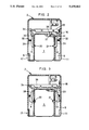
- FIGS. 2 and 3 are cross sections of a compact memory cartridge mounted on the adapter shown in FIG. 1;
- FIG. 4 illustrates a system arrangement showing how a compact memory cartridge is used
- FIGS. 5 to 9 are perspective views of adapters and compact memory cartridges according to other embodiments.
- FIG. 10 is a perspective view of an adapter with a connector and a compact memory cartridge according to another embodiment
- FIGS. 11 and 12 are cross sections of a compact memory cartridge mounted on the adapter shown in FIG.
- FIGS. 13 to 16 are perspective views of adapters each provided with a connector, and compact memory cartridges, according to other embodiments of this invention.
- FIG. 17 is a perspective view of an adapter and a compact memory cartridge according to an embodiment of this invention, wherein, if the compact memory cartridge is pushed into the adapter with its top and bottom surfaces being reversed, it is prevented from being guided thereinto;
- FIG. 18 is a perspective view of a compact memory cartridge to be guided into the adapter shown in FIG. 17, according to another embodiment of this invention.
- FIG. 19 is a perspective view of the memory cartridge system shown in FIG. 17, and a reproducing apparatus for loading the system;
- FIG. 20 shows an adapter and a compact memory cartridge according to an embodiment of this invention, wherein, if the compact memory cartridge is pushed into the adapter with its top and bottom surfaces or its right and left sides being reversed, it is prevented from being guided thereinto.
- the adapter 2 is formed with a pair of arms 5 and 6 integrally with the adapter body, and is configured generally in a U shape in a plan view.
- This adapter 2 has a thickness substantially the same as that of a compact memory cartridge 3 which is inserted within a space 4 between the arms 5 and 6 in the direction indicated by an arrow, resulting in an adapter/cartridge combination having the same shape and size as a larger, standard memory cartridge 41 (FIG. 4).
- the compact memory cartridge 3 has the same thickness as the standard memory cartridge 41, but may be made thinner than the standard memory cartridge 41.
- Two guide protrusions 7 are provided on an inner side wall of the arm 5.
- a guide groove 8 is provided in an inner side wall of the arm 6.
- the guide protrusions 7 and guide groove 8 come into engagement with a guide groove and guide protrusions, respectively, of the compact memory cartridge 3 to be described later, for regulating the position of the compact memory cartridge 3 in the thickness direction with respect to the adapter 2. Since the guide members provided at the arms 5 and 6 have different shapes, the incorrect insertion of the compact memory cartridge 3 with its right and left side reversed can be prevented.
- An engagement claw 9 is provided between two guide protrusions 7, the claw 9 being capable of being retracted into and extended out of the arm 5.
- a similar engagement claw 10 (FIG. 2) also is provided for the arm 6.
- a protrusion 11 and a groove 17 are formed at the end portions on opposite outer sides of the arms 5 and 6.
- the protrusion 11 and groove 17 serve to prevent incorrect insertion, including a reversal of top and bottom surfaces and right and left sides, of the adapter 2 holding the compact memory cartridge 3.
- the adapter 2 contains a battery 12 with a rather large capacity which is replaced with a new battery when necessary.
- This battery 12 is connected via connection or terminal pins 13 to a memory circuit (not shown) of the compact memory cartridge 3 to back it up.
- a slidable write protect lever 15 (FIG. 2) which couples with a write protect knob 37 of the compact memory cartridge 3 when the compact memory cartridge 3 is mounted on the adapter 2.
- a lock release knob 16 is mounted on one side of the adapter 2 for releasing a lock by the engagement claws 9 and 10.
- a groove 22 and protrusions 23 are formed on respective opposite sides of the compact memory cartridge 3, for engagement with the guide protrusions 7 and the guide groove 8 of the adapter 2.
- a pair of terminal holes 24 into which the terminal pins 13 are inserted.
- a female connector 26 having a number of terminal holes is mounted. When this female connector 26 is mated with a male connector 47 (FIG. 4) of the reproducing apparatus 40, the reproducing apparatus 40 can read or write image data into or from the compact memory cartridge 3.
- a battery 27 backs up the memory circuit of the compact memory cartridge 3.
- the engagement claws 9 and 10 are rotatably mounted about pins 30 and 31 within the arms 5 and 6, and are biased by springs 32 and 33.
- One end of the engaging claw 9 is in contact with a rotatable lever 34.
- a slide arm 35 also is provided to pivot the engagement claw 10 and the rotatable lever 34, the slide arm 35 being moved by the lock release knob 16.
- This slide arm 35 is mounted within the adapter 2, and is slidable in the right and left directions by means of pins and slots.
- One end of the write protect lever 15 extends from the upper end of the adapter 2, the other end forming a bifurcated portion 36 coupled with the write protect knob 37.
- the compact memory cartridge 3 In mounting the compact memory cartridge 3 on the adapter 2, the compact memory cartridge 3 is directed toward the space 4 while positioning the female connector 26 at the outer side, and then is pushed and inserted between the arms 5 and 6 while putting the groove 22 and protrusions 23 into engagement with the corresponding guide protrusions 7 and guide groove 8.
- the engagement claws 9 and 10 come into engagement with the recesses 20 and 21, and the terminal pins 13 are inserted into the terminal holes 24.
- the terminal pins 13 are coupled with the terminal holes 24, the back-up power supply for the compact memory cartridge 3 is switched from the battery 27 to the battery 12 so as not to consume the battery 27. Since the opposite sides of the compact memory cartridge 3 have different shapes, the cartridge 3 cannot be inserted into the adapter 2 with the right and left sides reversed. Thus, the dimension of the adapter 2 with the compact memory cartridge 3 mounted thereon becomes the same as the standard memory cartridge 41.
- the lock release knob 16 is slid to the position shown in FIG. 3.
- the slide arm 35 is moved to the left, and the engagement claw 10 is rotated counterclockwise while the engagement claw 9 is rotated clockwise.
- These engagement claws 9 and 10 rotate against the forces of the springs 32 and 33 to get out of the recesses 20 and 21.
- the cartridge 3 can be removed from the adapter 2 when the cartridge 3 is moved in the direction opposite that shown by the arrow in FIG. 1.
- FIG. 4 shows how a memory cartridge system is used.
- a standard memory cartridge also is shown for the sake of reference.
- the standard memory cartridge has the same shape and dimension as the adapter 2 with the compact memory cartridge 3 mounted therein.
- the standard memory cartridge 41 is formed with a groove 42 and a protrusion 43.
- This standard memory cartridge 41 is loaded in a standard type electronic still camera (not shown), and image data of recorded scenes is written in a memory circuit. After taking scenes with the electronic still camera, the standard memory cartridge 41 is mounted on a reproducing apparatus 40 to read stored image data. The read-out image data can be displayed on a home television set connected to the reproducing apparatus, or transformed into a hard copy by means of a video printer connected to the reproducing apparatus 40. At the head of the standard memory cartridge 41, there is mounted a female connector 50 having a number of terminal holes, the connector 50 having the same structure as the female connector 26 mounted on the compact memory cartridge 3.
- the reproducing apparatus 40 has a loading chamber 46 within which the standard memory cartridge 41 is housed.
- the width and height of the loading chamber 46 are substantially the same as the standard memory cartridge 41.
- the depth of the loading chamber 46 is shorter than the length of the standard memory cartridge 41 so that when it is housed within the loading chamber 46, the bottom end thereof extends out of the chamber 46.
- the cartridge 41 By holding and pulling the bottom end of the standard memory cartridge 41 with one's fingers, the cartridge 41 it can be ejected from the loading chamber 46.
- a male connector 47 which can be coupled to the female connector 50 of the standard memory cartridge 41, the male connector 47 also having a plurality of terminal pins 48.
- an engaging member 45a and a protrusion 45b adapted to be engaged with the protrusion 43 and the groove 42 of the standard memory cartridge 41, respectively. Since the shapes of both lateral ends of the loading chamber 46 at the bottom thereof are different, if the standard memory cartridge 41 is inserted into the loading chamber with its top and bottom surfaces or right and left sides being reversed, the head of the standard memory cartridge 41 will not reach the bottom end of the loading chamber, but it is stopped in the middle of insertion. Therefore, the terminal pins 48 of the male connector 47 are prevented from being bent by the standard memory cartridge 41.
- the compact memory cartridge 3 which is smaller in dimension than the standard memory cartridge 41, is loaded into the electronic still camera 55 in order to make the camera compact and light.
- a loading chamber 51 of the electronic still camera 55 has a size substantially the same as that of the compact memory cartridge 3.
- a male connector 61 which is coupled to the female connector 26 of the compact memory cartridge 3.
- the end of the compact memory cartridge 3 is exposed from the electric still camera 55 so that the write protect knob 37 can be operated to select one of a write enabled mode and a write inhibited mode.
- the compact memory cartridge 3 is mounted on the adapter 2, as described previously.
- the shape and size of the adapter 2 with the compact memory cartridge 3 mounted thereon are the same as those of the standard memory cartridge 41.
- the compact memory cartridge 3 can be housed correctly within the loading chamber 46.
- the end of the adapter 2 extending out of the loading chamber is held with fingers and pulled backward so that the adapter 2 along with the compact memory cartridge 3 can be removed from the loading chamber 46. Since the lock release knob 16 is within the loading chamber 46, there is no fear that the lock release knob 16 will be actuated while the adapter 2 is removed, or that the compact memory cartridge 3 will be left within the loading chamber 46.
- the compact memory cartridge 3 can be mounted on an electronic still camera designed for a standard memory cartridge 41.
- the write protect knob 37 of the compact memory cartridge 3 can be actuated by the write protect lever 15 while it is mounted on the electronic still camera.
- FIG. 5 shows another embodiment of the memory cartridge system.
- An adapter 65 is configured in an L shape.
- the shape and size of the adapter 65 with a compact memory cartridge 68 being mounted thereon are the same as those of the standard memory cartridge 41.
- the adapter 65 is provided with a T-shaped guide protrusion 66, a hook 67, and a groove 70.
- the compact memory cartridge 68 is provided with a T-shaped groove 69 for engagement with the guide protrusion 66, an engagement hole (not shown) for engagement with the hook 67, and a protrusion 71.
- the groove 69 comes into engagement with the protrusion 66 so that the compact memory cartridge 68 is held securely by the adapter 65. Thereafter, the hook 67 enters the engagement hole to lock the compact memory cartridge 68 in place.
- This hook 67 is formed integrally with a release knob 67a. When the release knob 67a is depressed, the hook 67 moves to release the engagement with the compact memory cartridge 68.
- the female connector 72 is located at one side of the adapter 65. The result is a reproducing apparatus whose male connector is displaced correspondingly.
- FIG. 6 shows a further embodiment of the memory cartridge system.
- a compact memory cartridge 74 of this embodiment has the same width and thickness as the standard memory cartridge 41, and a shorter length.
- On the front surface of the adapter 74 there is formed a T-shaped guide protrusion 75, and a projection 76 at one side thereof. This projection 76 is provided with a known click ball 77.
- the compact memory cartridge 79 on the other hand is provided with a T-shaped groove 80 adapted to engage with the guide protrusion 75, a protrusion 81 and a groove 82 for controlling the insertion thereof into a reproducing apparatus 40, and a female connector 83.
- the adapter 74 constructed in this fashion is slid into the compact memory cartridge 79 in the direction indicated by an arrow.
- the compact memory cartridge 79 is held in position by the click ball 77 so as not to be detached from the adapter 74.
- the guide protrusion 75 extends in a direction perpendicular to the direction of insertion of the adapter into the reproducing apparatus 40, the compact memory cartridge 79 will not be detached from the adapter 74 or left within the reproducing apparatus 40, even if no lock mechanism is provided.
- FIG. 7 shows a memory cartridge system in which an adapter is mounted on a compact memory cartridge having the same thickness and length as those of the standard memory cartridge, but a narrower width.
- the adapters 87 and 88 are coupled to the compact memory cartridge 86 at opposite sides thereof. The shape and dimension in this state are the same as those of the standard memory cartridge 41.
- the adapter 88 is provided with a protrusion 94 and a groove 95 respectively adapted to engage with a groove 92 and a protrusion 93 of the compact memory cartridge 86, and a hook 96. This hook 96 moves against the spring force to release the engagement with the compact memory cartridge 86 when a lever 97 is actuated.
- the adapter 87 is provided with two positioning protrusions 89 adapted to engage with a pair of grooves 91 formed on the compact memory cartridge 86, and a hook 90 adapted to engage with the compact memory cartridge 86. When pushed in the directions indicated by the arrows, these adapters 87 and 88 are coupled fixedly to the compact memory cartridge 86 at opposite sides thereof. A groove 98 and a protrusion 99 are provided for preventing erroneous loading of the adapters into the reproducing apparatus 40.
- Reference numeral 100 represents a female connector.
- FIG. 8 shows an embodiment wherein an adapter 103 is coupled to a compact memory cartridge 102 at only one side thereof.
- the adapter 103 is provided with two protrusions 105 adapted to engage with grooves 104 formed at opposite end portions of one side of the compact memory cartridge 102, and a hook 106.
- this adapter is used for a similar reproducing apparatus as described with respect to the embodiment shown in FIG. 5.
- a protrusion 108 and a groove 109 are provided for preventing erroneous loading of the adapter into the reproducing apparatus 40.
- FIG. 9 shows an embodiment wherein an adapter 112 clamps a compact memory cartridge by means of a slidable or movable arm 113 and a fixed arm 114.
- the movable arm 113 provided with two grooves 116, is biased toward the fixed arm 114 by a spring 115.
- the fixed arm 114 is provided with a pair of protrusions 117.
- the compact memory cartridge 111 is provided with protrusions 118 adapted to engage with the grooves 116 of the movable arm 113. As the compact memory cartridge 111 is guided within the adapter 112, the movable arm 113 is forced to retract against the force of the spring 115 so as to elongate the distance to the fixed arm 114.
- the movable arm 113 goes back to engage the grooves 116 with the protrusions 118 of the compact memory cartridge 111.
- the grooves 119 of the compact memory cartridge 111 come into engagement with the protrusions 117 of the fixed arm 114.
- This squeezing force should be set larger than the coupling force between a female connector 122 and the male connector 47, so that the compact memory cartridge 111 will not be detached from the adapter 112.
- Reference numeral 120 represents a protrusion, and 121 a groove.
- the female connector of the compact memory cartridge has the same structure as that of the standard memory cartridge so enable direct electrical connection of the compact memory cartridge to the reproducing apparatus.
- the female connector of the compact memory cartridge cannot be coupled to the male connector of the reproducing apparatus.
- a compact memory cartridge having a small female connector is arranged to be connectable electrically to a reproducing apparatus.
- elements similar to those shown in FIGS. 1 to 3 are represented by using identical reference numerals.
- a compact memory cartridge 125 is provided with a female connector 126 having a number of terminal holes 126a. The size of the female connector 126 is different from that of the female connector 50 of the standard memory cartridge 41.
- This female connector 126 is coupled to a male connector 128 having a number of terminal pins 129 mounted on the inner wall of an adapter 127.
- This male connector 128 is connected via lead wires 129 to a female connector 130 which is of the same type as the female connector 50 Of the standard memory cartridge 3.
- Reference numerals 132 and 133 represent lids for the battery spaces.
- the female connector 126 is coupled with the male connector 128.
- the adapter 127 along with the compact memory cartridge 125 is loaded within the loading chamber 46 while directing the female connector 130 toward the loading chamber 46.
- the female connector 130 has been coupled to the male connector 47 of the reproducing apparatus 40. In this manner, the compact memory cartridge 125 can be connected electrically to the reproducing apparatus 40 via the adapter 127.
- FIG. 13 shows a memory cartridge system having an L-shaped adapter.
- This adapter 135 is similar to the adapter 65 shown in FIG. 5, with like elements being represented by identical reference numerals.
- the adapter 135 is provided with a male connector 137 to be coupled to a female connector 72 of a compact memory cartridge 136, and a female connector 138 of the same type as the female connector 50 of a standard memory cartridge 41.
- Reference numeral 139 represents a positioning protrusion
- reference numeral 140 represents a lid for a battery space.
- the adapter 135 is loaded within the reproducing apparatus, with the female connector 138 being directed toward the reproducing apparatus.
- FIG. 14 shows an embodiment wherein, if a compact memory cartridge with the right and left sides or top and bottom reversed is pushed into the adapter, it is stopped at the middle of insertion.
- This compact memory cartridge 145 has the same width and thickness as the standard memory cartridge 41, and a shorter length.
- an adapter 147 is fitted to the compact memory cartridge 145.
- a male connector is mounted at the tip of the extended portion 146 of the compact memory cartridge 145, for coupling to a female connector 148 of the adapter 147.
- Recesses 150 and 151 are formed on opposite sides of this extended portion 146.
- a groove (not shown) is formed on the side of the recess 150, and a protrusion 152 is formed on the side of the recess 151.
- Reference numeral 153 represents a lid for a battery space
- reference numeral 154 represents a write protect knob.
- the adapter 147 is provided with a female connector 156 of the same type as the female connector of the standard memory cartridge.
- the female connector 156 is connected electrically to a male connector 148.
- Engagement claws 160 and 161 are formed at the distal end portions of arms 158 and 159 of the adapter 147, for engagement with the recesses 150 and 151. These engagement claws 160 and 161 are unlocked by a lock release knob 157 provided at the side wall of the adapter 147.
- a protrusion 162, for engagement with the groove of the compact memory cartridge 145, is formed on the arm 158, and a guide groove 163, for engagement with the protrusion 152, is formed on the arm 159.
- Reference numeral 164 represents a protrusion adapted to engage with the guide groove 45a of the reproducing apparatus 40.
- a compact memory cartridge 166 is provided with a protruded female connector 167 which is inserted into a hole defined by a male connector 169 of an adapter 168. This engagement between both the connectors 167 and 169 provides a cantilever support of the compact memory cartridge 166 by the adapter 168.
- a female connector 170 to be coupled to the connector 47 of the reproducing apparatus 40 is connected electrically to the male connector 169. It is preferable to provide the above-described guide means and lock mechanism also in the present embodiment.
- An adapter 173 shown in FIG. 16 is formed with a generally rectangular recess 174 opening to one side of the adapter 173.
- a male connector is mounted at a bottom of the recess 174, for electrical connection to a female connector 181.
- a guide protrusion 176 and a guide groove 177, extending in a direction of insertion of a compact memory cartridge 178, are formed on opposite inner walls of the recess 174.
- This compact memory cartridge 178 is provided with a groove 179 for engagement with the guide protrusion 176, and a protrusion 180 for engagement with the guide groove 177.
- the compact memory cartridge 178 is guided into the recess 174 in the direction indicated by an arrow.
- Reference numeral 182 represents a female connector. Since the direction of guiding the compact memory cartridge 178 is perpendicular to the direction of loading the adapter 173 into the reproducing apparatus 40, it is not necessary to provide a lock mechanism for locking the compact memory cartridge 178 to the adapter 173, thereby reducing manufacturing cost.
- the width of a guide groove 187 of an arm 5 is determined to be wider than that of a guide groove 188 of an arm 6.
- the guide groove 187 does not extend up to the bottom of a recess, a distance L2 being set between the end 187a of the groove 187 and the bottom of the recess being flush with a male connector 128. This distance L2 is longer than the length L1 of a terminal pin 129 of the male connector 128.
- the guide groove 188 is formed similarly.
- Reference numeral 189 represents a protrusion for regulating the direction of guidance.
- the compact memory cartridge 186 is provided with a protrusion 190 adapted to engage with the guide groove 187, and a protrusion 191 adapted to engage with the guide groove 188, respectively at opposite side walls of the cartridge 186.
- the distance between the end 191a of the protrusion 191 and the surface of a female connector 126 is set to L2.
- the compact memory cartridge 186 can be mounted on the adapter 185 such that the female connector 126 is coupled reliably to the male connector 128.
- the compact memory cartridge 186 with its right and left sides reversed is intended to be guided, it cannot be inserted into the recess 4 of the adapter 185 because of different widths of the guide grooves 187 and 188. Furthermore, if the compact memory cartridge 186 is guided correctly setting its right and left sides but incorrectly setting its top and bottom surfaces, i.e., if the cartridge is guided while directing the battery lid 133 toward the recess 4, the surface of the battery lid 133 is guided only to the position spaced by the distance L2 from the bottom of the recess. Therefore, the surface of the battery lid 133 will not abut the terminal pins 129 of the male connector 128 or will not break these terminal pins 129.
- a compact memory cartridge 195 shown in FIG. 18 is provided with four separated guide protrusions 190a, 190b, 191a, and 191b.
- the operation and function of this embodiment are the same as the embodiment shown in FIG. 17.
- FIG. 19 shows a reproducing apparatus used with the memory cartridge system shown in FIG. 17 or 18.
- elements similar to those shown in FIG. 4 are represented by identical reference numerals.
- this reproducing apparatus 196 a groove is formed on one inner side wall of a loading chamber 46 for engagement with the protrusion 189.
- This protrusion 197 prevents the adapter 85 from being inserted with its right and left sides reversed.
- FIG. 20 shows a modification of the memory cartridge system shown in FIG. 17.
- An adapter 200 of this embodiment is provided with a guide protrusion 201 in place of the guide groove 188.
- This guide protrusion 201 is formed starting from the position retracted from the front end surface of an arm 6 by a length L2.
- a compact memory cartridge 202 is provided with a groove 203 leaving a stop area 203a. Therefore, in this embodiment, the compact memory cartridge 202 can be inserted into the adapter 200 only when the right and left sides are set correctly. If the right and left sides or the top and bottom surfaces are set incorrectly, the compact memory cartridge 202 cannot be inserted into the adapter 200 at all.
- the memory circuit used with the above embodiments is a volatile memory circuit.
- a nonvolatile memory circuit may also be used instead.
- an adapter may have a check circuit for checking the voltage of a battery within the compact memory cartridge, a buffer memory circuit, and the like incorporated therein.
Abstract
Description
Claims (31)
Applications Claiming Priority (6)
| Application Number | Priority Date | Filing Date | Title |
|---|---|---|---|
| JP1575890U JPH03106599U (en) | 1990-02-19 | 1990-02-19 | |
| JP2-15757[U] | 1990-02-19 | ||
| JP1575790U JPH03106598U (en) | 1990-02-19 | 1990-02-19 | |
| JP2-15758[U]JPX | 1990-02-19 | ||
| JP3203690U JPH03124262U (en) | 1990-03-28 | 1990-03-28 | |
| JP3723590U JPH03130098U (en) | 1990-04-06 | 1990-04-06 |
Publications (1)
| Publication Number | Publication Date |
|---|---|
| US5155663A true US5155663A (en) | 1992-10-13 |
Family
ID=27456441
Family Applications (1)
| Application Number | Title | Priority Date | Filing Date |
|---|---|---|---|
| US07/656,650 Expired - Lifetime US5155663A (en) | 1990-02-19 | 1991-02-19 | Memory cartridge system with adapter |
Country Status (1)
| Country | Link |
|---|---|
| US (1) | US5155663A (en) |
Cited By (149)
| Publication number | Priority date | Publication date | Assignee | Title |
|---|---|---|---|---|
| DE4316193A1 (en) * | 1993-05-14 | 1994-11-24 | Stocko Metallwarenfab Henkels | Device for producing a detachable electrical plug connection between a module and an electrical circuit |
| FR2705557A1 (en) * | 1993-05-28 | 1994-12-02 | Pvb Medizintechnik Gmbh | Support plate, in particular for medical devices. |
| US5395112A (en) * | 1992-05-20 | 1995-03-07 | Codemasters Limited | Memory cartridge |
| US5417395A (en) * | 1993-06-30 | 1995-05-23 | Medex, Inc. | Modular interconnecting component support plate |
| WO1995018475A1 (en) * | 1993-12-29 | 1995-07-06 | Berg Electronics Manufacturing B.V. | Electrical connector |
| DE29506344U1 (en) * | 1995-04-12 | 1995-08-03 | Stocko Metallwarenfab Henkels | Contact unit for card-shaped carrier elements |
| US5465934A (en) * | 1993-12-17 | 1995-11-14 | Silicon Graphics, Inc. | Bracket for a CPU daughter card |
| US5473505A (en) * | 1992-10-19 | 1995-12-05 | Kabushiki Kaisha Toshiba | IC card data processing device which can be integrally housed within a computer |
| US5472351A (en) * | 1993-10-06 | 1995-12-05 | U.S. Robotics, Inc. | Personal computer modem card interface construction |
| US5483422A (en) * | 1994-09-23 | 1996-01-09 | Hewlett-Packard Company | Keying card guide for PC card |
| US5513074A (en) * | 1992-11-16 | 1996-04-30 | International Business Machines Corporation | Tandem circuit cards |
| DE19512255A1 (en) * | 1995-03-31 | 1996-10-02 | Siemens Ag | Arrangement for receiving an insert body in a receiving body |
| US5562504A (en) * | 1995-01-04 | 1996-10-08 | Simple Technology Incorporated | Communications card with integral transmission media line adaptor |
| US5599232A (en) * | 1992-05-02 | 1997-02-04 | Codemasters Limited | Memory cartridge with interface having graphics co-processor |
| WO1997023819A1 (en) * | 1995-12-14 | 1997-07-03 | Motorola Inc. | Reusable housing and memory card therefor |
| US5650917A (en) * | 1996-10-09 | 1997-07-22 | Hsu; Fu-Yu | CPU card mounting structure |
| US5653638A (en) * | 1994-08-31 | 1997-08-05 | Nintendo Co., Ltd. | Cartridge for game machine |
| US5660568A (en) * | 1995-01-04 | 1997-08-26 | Simple Technology, Inc. | Communications card with integral transmission media line adaptor |
| WO1997044867A1 (en) * | 1996-05-24 | 1997-11-27 | Itt Manufacturing Enterprises, Inc. | Smart card computer adaptor |
| US5695364A (en) * | 1993-06-02 | 1997-12-09 | Japan Aviation Electronics Industry, Limited | Connector memory for an IC memory card with a small thickness |
| US5752918A (en) | 1993-06-30 | 1998-05-19 | Medex, Inc. | Modular medical pressure transducer |
| US5761682A (en) * | 1995-12-14 | 1998-06-02 | Motorola, Inc. | Electronic book and method of capturing and storing a quote therein |
| US5761681A (en) * | 1995-12-14 | 1998-06-02 | Motorola, Inc. | Method of substituting names in an electronic book |
| US5815407A (en) * | 1995-12-14 | 1998-09-29 | Motorola Inc. | Method and device for inhibiting the operation of an electronic device during take-off and landing of an aircraft |
| US5822190A (en) * | 1996-06-11 | 1998-10-13 | Kabushiki Kaisha Toshiba | Card type memory device and a method for manufacturing the same |
| US5829723A (en) * | 1995-06-28 | 1998-11-03 | Medex, Inc. | Medical device mounting structure |
| US5836775A (en) * | 1993-05-13 | 1998-11-17 | Berg Tehnology, Inc. | Connector apparatus |
| US5844475A (en) * | 1995-10-11 | 1998-12-01 | Sumitomo Rubber Industries, Inc. | Apparatus for alarming abnormality of tire air pressure |
| US5868678A (en) | 1993-06-30 | 1999-02-09 | Medex, Inc. | Two-part medical pressure transducer with diaphragm stand-offs |
| US5887118A (en) * | 1997-02-12 | 1999-03-23 | Motorola, Inc. | Olfactory card |
| US5889649A (en) * | 1994-03-01 | 1999-03-30 | Canon Kabushiki Kaisha | Information processing apparatus and a card-shaped adapter for smaller and larger storage medium |
| US5893132A (en) * | 1995-12-14 | 1999-04-06 | Motorola, Inc. | Method and system for encoding a book for reading using an electronic book |
| US5902137A (en) * | 1993-12-29 | 1999-05-11 | Berg Technology, Inc. | Electrical connector |
| EP0915474A1 (en) * | 1997-10-15 | 1999-05-12 | Yao, Li-ho | An adapter base for receiving a cartridge memory |
| US5941775A (en) * | 1994-10-14 | 1999-08-24 | Sega Of America, Inc. | Data processing system, method thereof and memory cassette |
| US5969333A (en) * | 1995-04-05 | 1999-10-19 | Gemplus | Data collection system for card readers |
| US6002605A (en) * | 1997-02-28 | 1999-12-14 | Kabushiki Kaisha Toshiba | Connecting apparatus, and information processing apparatus |
| WO1999067751A2 (en) * | 1998-06-23 | 1999-12-29 | Intel Corporation | Low pin count card retainer |
| US6022763A (en) * | 1996-05-10 | 2000-02-08 | Kabushiki Kaisha Toshiba | Substrate for semiconductor device, semiconductor device using the same, and method for manufacture thereof |
| US6054774A (en) * | 1994-03-22 | 2000-04-25 | Kabushiki Kaisha Toshiba | Thin type semiconductor package |
| USRE36769E (en) * | 1991-04-30 | 2000-07-11 | Fujitsu Limited | Card type input/output interface device and electronic device using the same |
| EP1022645A2 (en) * | 1999-01-21 | 2000-07-26 | Japan Solderless Terminal Mfg. Co., Ltd. | Card connection adaptor |
| US6102720A (en) * | 1998-04-28 | 2000-08-15 | Hon Hai Precision Ind. Co., Ltd. | Ejector mechanism with elastic means in receptacle |
| US6109934A (en) * | 1998-11-30 | 2000-08-29 | 3Com Corporation | Connector for connecting an electronic device to a communications card |
| US6128200A (en) * | 1998-02-18 | 2000-10-03 | Chu; Ho-Kang | Butt-joint CPU mounting structure |
| US6141210A (en) * | 1993-07-23 | 2000-10-31 | Kabushiki Kaisha Toshiba | External storage device |
| EP1052590A1 (en) * | 1999-04-23 | 2000-11-15 | J.S.T. Mfg. Co., Ltd. | Card connection adaptor |
| DE19922976A1 (en) * | 1999-05-19 | 2000-12-07 | Bosch Gmbh Robert | Device and method for holding cards on a device housing |
| US6166431A (en) * | 1995-08-25 | 2000-12-26 | Kabushiki Kaisha Tishiba | Semiconductor device with a thickness of 1 MM or less |
| DE19940588A1 (en) * | 1999-06-14 | 2001-01-04 | Delta Electronics Inc | Contact device for use in fan replaceable under voltage, has engagement elements on plate element and heat extraction device so plate element can be fixed by in heat extraction device |
| US6186803B1 (en) | 1997-11-21 | 2001-02-13 | 3Com Corporation | Breakaway physical/electrical media jack |
| US6201295B1 (en) | 1993-04-28 | 2001-03-13 | Kabushiki Kaisha Toshiba | Plate-shaped external storage device and method of producing the same |
| US6219256B1 (en) * | 1997-10-21 | 2001-04-17 | Hon Hai Precision Ind. Co., Ltd. | Card adapter interfacing between a card connector and a memory card |
| US6224391B1 (en) | 1997-06-11 | 2001-05-01 | Matsushita Electric Industrial Co., Ltd. | Memory card adaptor card |
| US6266724B1 (en) | 1993-09-01 | 2001-07-24 | Sandisk Corporation | Removable mother/daughter peripheral card |
| US20010019913A1 (en) * | 1998-08-20 | 2001-09-06 | David J. Llapitan | Retention mechanism for an electrical assembly |
| US6373706B1 (en) * | 1998-09-14 | 2002-04-16 | Fujitsu Limited | Electronic device having two slots different in width |
| US20020055285A1 (en) * | 1999-12-20 | 2002-05-09 | Rambus, Inc. | Chip socket assembly and chip file assembly for semiconductor chips |
| US20020116553A1 (en) * | 2000-11-10 | 2002-08-22 | Shigeo Matsumoto | Adapter device, memory device and integrated circuit chip |
| US6456491B1 (en) * | 1996-02-12 | 2002-09-24 | Gateway, Inc. | Modular floppy disk drive for internal and external use |
| US6457647B1 (en) * | 1993-11-16 | 2002-10-01 | Canon Kabushiki Kaisha | Memory card adaptor to facilitate upgrades and the like |
| US6506162B1 (en) * | 2000-06-09 | 2003-01-14 | K-Jump Health Co., Ltd. | Electronic blood pressure gauge equipped with dismountable external memory device |
| DE20119190U1 (en) * | 2001-11-27 | 2003-04-10 | Baumueller Nuernberg Gmbh | Electronics chassis for mounting and holding electronic circuit boards |
| US6547602B2 (en) * | 2001-08-23 | 2003-04-15 | 3Com Corporation | Modular plug receptacles defined by multiple electronic components |
| US6567273B1 (en) * | 2002-02-06 | 2003-05-20 | Carry Computer Eng. Co., Ltd. | Small silicon disk card with a USB plug |
| US6570767B1 (en) * | 1999-08-10 | 2003-05-27 | Nokia Mobile Phones Ltd. | Card adapter |
| US6575375B1 (en) * | 1999-05-31 | 2003-06-10 | Gemplus | Portable integrated circuit device and method for the production thereof |
| EP1152426A3 (en) * | 2000-04-20 | 2003-07-02 | Sony Corporation | Adaptor device and input/output device |
| US6589059B2 (en) | 1995-05-26 | 2003-07-08 | Rambus, Inc. | Chip socket assembly and chip file assembly for semiconductor chips |
| US6592400B2 (en) | 1999-08-30 | 2003-07-15 | Delta Electronics, Inc. | Easily assembled fan structure feasible for hot swap |
| US20030135470A1 (en) * | 2002-01-16 | 2003-07-17 | Beard Robert E. | Method and system for credit card purchases |
| US6611432B2 (en) * | 2001-01-26 | 2003-08-26 | Dell Products L.P. | Docking bracket for rack-mounted computing modules |
| US6612498B1 (en) * | 1999-03-11 | 2003-09-02 | Nokia Mobile Phones Ltd. | Method and means for using additional cards in a mobile station |
| US6616053B2 (en) * | 1997-06-04 | 2003-09-09 | Sony Corporation | Memory card, and receptacle for same |
| WO2004011814A1 (en) * | 2002-07-29 | 2004-02-05 | Gn Netcom A/S | Method and apparatus for mounting selectively orientable component |
| US20040035939A1 (en) * | 2002-08-21 | 2004-02-26 | Jin-Min Lin | Multifunction memory card reading/writing device |
| US20040047210A1 (en) * | 1998-03-26 | 2004-03-11 | Kabushiki Kaisha Toshiba | Storage apparatus, card type string apparatus, and electronic apparatus |
| US20040089717A1 (en) * | 2002-11-13 | 2004-05-13 | Sandisk Corporation | Universal non-volatile memory card used with various different standard cards containing a memory controller |
| US20040090751A1 (en) * | 2002-11-08 | 2004-05-13 | Choi Dae Seon | Portable USB storage device |
| US20040103234A1 (en) * | 2002-11-21 | 2004-05-27 | Aviad Zer | Combination non-volatile memory and input-output card with direct memory access |
| US20040184246A1 (en) * | 2001-11-19 | 2004-09-23 | Le Trung V. | Device having a slot capable of receiving at least four types of memory cards |
| US20040190386A1 (en) * | 2003-03-31 | 2004-09-30 | Fujitsu Limited | Card-type terminal |
| US20040210715A1 (en) * | 2003-04-17 | 2004-10-21 | Eliyahou Harari | Memory cards including a standard security function |
| EP1473659A2 (en) * | 2003-04-30 | 2004-11-03 | Valeo Securite Habitacle S.A.S. | Arrangement for blocking a data carrier in a device for data exchange |
| US6844890B1 (en) * | 2003-10-10 | 2005-01-18 | Hitachi Printing Solutions America, Inc. | Toner cartridge adaptor |
| US20050013038A1 (en) * | 2003-04-03 | 2005-01-20 | Wataru Abe | Magnetic disk device and electronic apparatus for mounting the magnetic disk device thereto |
| US20050037671A1 (en) * | 2002-10-15 | 2005-02-17 | Hiroyuki Yamada | Adapter, memory card, and memory card module |
| US20050055479A1 (en) * | 2002-11-21 | 2005-03-10 | Aviad Zer | Multi-module circuit card with inter-module direct memory access |
| US6893268B1 (en) | 1993-09-01 | 2005-05-17 | Sandisk Corporation | Removable mother/daughter peripheral card |
| US20050125584A1 (en) * | 2003-12-09 | 2005-06-09 | Yosi Pinto | Efficient connection between modules of removable electronic circuit cards |
| US20050229198A1 (en) * | 2004-04-08 | 2005-10-13 | Christie Leslie G Jr | Data storage means |
| US20050230483A1 (en) * | 2004-04-16 | 2005-10-20 | Miller Robert C | Memory card with two standard sets of contacts and a contact covering mechanism |
| US20050230484A1 (en) * | 2004-04-16 | 2005-10-20 | Cuellar Edwin J | Memory cards having two standard sets of contacts |
| US20060124739A1 (en) * | 2002-10-25 | 2006-06-15 | Yutaka Kojima | Memory card adapter for connecting a miniature card to a standard card connector, along with a method of fabricating same |
| US20060142876A1 (en) * | 2002-12-19 | 2006-06-29 | Phoenix Contact Gmbh & Co. Kg | Location-specific adaptation of an intelligent unit |
| US20060176673A1 (en) * | 2005-01-31 | 2006-08-10 | Stmicroelectronics S.R.L | Removable data storage device and related assembling method |
| US7092256B1 (en) | 2002-04-26 | 2006-08-15 | Sandisk Corporation | Retractable card adapter |
| US7107378B1 (en) | 2000-09-01 | 2006-09-12 | Sandisk Corporation | Cooperative interconnection and operation of a non-volatile memory card and an input-output card |
| US20060206677A1 (en) * | 2003-07-03 | 2006-09-14 | Electronics And Telecommunications Research Institute | System and method of an efficient snapshot for shared large storage |
| US20070008695A1 (en) * | 2005-07-11 | 2007-01-11 | Peng-Hui Chou | Removable hard disc loading device |
| US7214100B1 (en) * | 2005-11-14 | 2007-05-08 | Hewlett-Packard Development Company, L.P. | Cable assembly |
| US20070172293A1 (en) * | 2004-03-24 | 2007-07-26 | Dymo | Tape printer |
| US20070222302A1 (en) * | 2006-03-22 | 2007-09-27 | Phoenix Contact Gmbh & Co. Kg | Electrical field device and expansion module for insertion into an electrical field device |
| US20070242423A1 (en) * | 2006-04-11 | 2007-10-18 | Schroff Gmbh | Shelf for electronic plug-in devices |
| US20080030963A1 (en) * | 2005-08-02 | 2008-02-07 | Warren Middlekauff | Memory Card With Latching Mechanism for Hinged Cover |
| US7359204B1 (en) * | 2006-02-15 | 2008-04-15 | Amkor Technology, Inc. | Multiple cover memory card |
| WO2008081425A2 (en) * | 2007-01-04 | 2008-07-10 | Sandisk Il Ltd. | Peripheral device for connection with a host |
| US20080173598A1 (en) * | 2007-01-18 | 2008-07-24 | Carl Fiorentino | Holder for a plurality of memory devices |
| US7440774B2 (en) | 2002-04-08 | 2008-10-21 | Socket Mobile, Inc. | Wireless enabled memory module |
| US7487908B1 (en) * | 1999-10-23 | 2009-02-10 | Ultracard, Inc. | Article having an embedded accessible storage member, apparatus and method for using same |
| US20090063743A1 (en) * | 2007-08-31 | 2009-03-05 | Sony Corporation | Card-type peripheral device |
| US20090077295A1 (en) * | 2007-09-14 | 2009-03-19 | Sony Corporation | Card-type peripheral device |
| US20100029330A1 (en) * | 2008-07-29 | 2010-02-04 | Novatel Wireless | Wireless device and assembly |
| US20100142920A1 (en) * | 1998-07-30 | 2010-06-10 | Tivo Inc. | Multimedia Signal Processing System |
| US20100149737A1 (en) * | 2008-12-12 | 2010-06-17 | Helen Shtargot | Adaptor for a router blade |
| US20100261369A1 (en) * | 2009-04-09 | 2010-10-14 | Kyocera Elco Corporation | Connector |
| US20100258459A1 (en) * | 2008-06-05 | 2010-10-14 | Kingston Technology Corporation | Credit-card-sized carrier of both standard and micro form-factor flash-memory cards |
| US20100291784A1 (en) * | 2009-05-12 | 2010-11-18 | Hon Hai Precision Industry Co., Ltd. | Elelctrical connector with latches holding module in place |
| USD628202S1 (en) * | 2009-10-20 | 2010-11-30 | Sandisk Corporation | MicroSD memory card with different color surfaces |
| USD638431S1 (en) * | 2009-10-20 | 2011-05-24 | Sandisk Corporation | MicroSD memory card with a semi-transparent color surface |
| US20110184757A1 (en) * | 2010-01-25 | 2011-07-28 | Daniel Isaac S | Interactive medical card and method of processing medical information stored thereon |
| US20110292588A1 (en) * | 2010-05-25 | 2011-12-01 | 2082053 Ontario Limited | Planar information device |
| US8380041B2 (en) * | 1998-07-30 | 2013-02-19 | Tivo Inc. | Transportable digital video recorder system |
| US8425140B2 (en) | 2010-06-08 | 2013-04-23 | Wistron Corporation | Fastening device and object having the same |
| US8491320B2 (en) * | 2011-12-27 | 2013-07-23 | Shenzhen Futaihong Precision Industry Co., Ltd. | Portable electronic device with chip card ejecting mechanism |
| US20130196527A1 (en) * | 2012-02-01 | 2013-08-01 | Zyxel Communications, Inc. | Lockable electrical connector |
| US8526781B2 (en) | 1998-07-30 | 2013-09-03 | Tivo Inc. | Multiple output digital video recording system |
| US20130250524A1 (en) * | 2012-03-20 | 2013-09-26 | Brocade Communications Systems, Inc. | Compact Flash Retainer |
| US20130273760A1 (en) * | 2012-04-17 | 2013-10-17 | Dai-Ichi Seiko Co., Ltd. | Electrical connector |
| US8577205B2 (en) | 1998-07-30 | 2013-11-05 | Tivo Inc. | Digital video recording system |
| US20130323943A1 (en) * | 2012-05-31 | 2013-12-05 | Fih (Hong Kong) Limited | Smart card securing mechanism and electronic device using same |
| CN103576760A (en) * | 2012-08-08 | 2014-02-12 | 纬创资通股份有限公司 | Electronic device and electronic module fixing structure |
| US8690283B2 (en) | 2009-10-20 | 2014-04-08 | Sandisk Il Ltd. | Method and system for printing graphical content onto a plurality of memory devices and for providing a visually distinguishable memory device |
| USD702692S1 (en) * | 2011-11-23 | 2014-04-15 | Digital Hard Copy | Card for holding a digital storage medium |
| USD702693S1 (en) * | 2011-11-23 | 2014-04-15 | Digital Hard Copy | Digital storage medium card |
| US20140314443A1 (en) * | 2010-06-11 | 2014-10-23 | Yasufumi Takahashi | Apparatus and method for preventing an information storage device from falling from a removable device |
| WO2015017017A1 (en) * | 2013-07-29 | 2015-02-05 | Raytheon Company | Rugged hard drive |
| KR200476919Y1 (en) * | 2013-10-11 | 2015-04-17 | 손정훈 | Portable storage device |
| US20150294721A1 (en) * | 2012-03-29 | 2015-10-15 | Sandisk Technologies Inc. | Memory Card |
| US9367712B1 (en) | 2007-03-01 | 2016-06-14 | Amkor Technology, Inc. | High density memory card using folded flex |
| US20160219746A1 (en) * | 2015-01-26 | 2016-07-28 | Fanuc Corporation | Structure for fixing printed board in electronic device unit |
| US9967534B1 (en) | 2004-11-19 | 2018-05-08 | Tivo Solutions Inc. | Digital video recorder video editing system |
| US10320100B2 (en) * | 2017-10-06 | 2019-06-11 | Te Connectivity Corporation | Card edge connector assembly |
| US20190205709A1 (en) * | 2016-07-29 | 2019-07-04 | Hewlett-Packard Development Company, L.P. | Electronic card holders |
| US20190220070A1 (en) * | 2018-01-17 | 2019-07-18 | Facebook, Inc. | Apparatus, system, and method for minimizing installation footprints of expansion cards |
| US10477706B1 (en) * | 2019-03-07 | 2019-11-12 | Shannon Systems Ltd. | Solid state memory device |
| US10645835B1 (en) * | 2019-01-29 | 2020-05-05 | Hewlett Packard Enterprise Development Lp | Option card latch and button |
| USD888009S1 (en) * | 2019-01-03 | 2020-06-23 | Ningbo Gecen Promotion & Gift Co., Ltd. | Ear phone |
| US20220071038A1 (en) * | 2020-08-25 | 2022-03-03 | Luxshare Precision Industry Company Limited | Adaptor |
Citations (23)
| Publication number | Priority date | Publication date | Assignee | Title |
|---|---|---|---|---|
| US3644684A (en) * | 1969-07-25 | 1972-02-22 | California Auto Radio Inc | Cassette to cartridge tape player adapter unit with self-contained drive mechanism |
| US3662123A (en) * | 1970-06-18 | 1972-05-09 | Motorola Inc | Cartridge adaptor |
| US4149027A (en) * | 1977-05-27 | 1979-04-10 | Atari, Inc. | TV game cartridge and method |
| EP0077876A1 (en) * | 1981-10-27 | 1983-05-04 | GRUNDIG E.M.V. Elektro-Mechanische Versuchsanstalt Max Grundig holländ. Stiftung & Co. KG. | Minicassette |
| JPS58143474A (en) * | 1982-02-18 | 1983-08-26 | Canon Inc | Adapter for tape cassette |
| JPS59101085A (en) * | 1982-11-30 | 1984-06-11 | Toshiba Corp | Adaptor for vtr |
| US4480835A (en) * | 1983-03-02 | 1984-11-06 | Williams Theodore R | Cartridge adapter for programmable video games |
| US4489351A (en) * | 1981-09-28 | 1984-12-18 | Staar S. A. | Electronic still camera with individual non-volatile memory units |
| US4494809A (en) * | 1983-02-15 | 1985-01-22 | Leonard Soloman | Security attachment for electrical plug |
| US4558384A (en) * | 1980-11-25 | 1985-12-10 | Victor Company Of Japan, Ltd. | Miniature type tape cassette and adapter means |
| US4602300A (en) * | 1981-01-20 | 1986-07-22 | Victor Company Of Japan, Ltd. | Adapter for a miniature type tape cassette |
| US4688121A (en) * | 1985-12-12 | 1987-08-18 | Sparkomatic Corporation | Cassette adaptor for 8-track cartridge tape player |
| US4744399A (en) * | 1986-07-31 | 1988-05-17 | Paccar Inc. | Central tire inflation system |
| US4780603A (en) * | 1985-03-25 | 1988-10-25 | Mips Co., Ltd. | Integrated circuit card and connector arrangement using same |
| US4812634A (en) * | 1987-07-13 | 1989-03-14 | Oki Electric Industry Co., Ltd. | IC card with a solar battery |
| JPH01166475A (en) * | 1987-12-23 | 1989-06-30 | Casio Comput Co Ltd | Connector for memory card |
| US4844465A (en) * | 1986-07-11 | 1989-07-04 | Nintendo Company, Ltd. | Adaptor of a cartridge for gaming machine |
| US4850891A (en) * | 1988-04-04 | 1989-07-25 | Augat Inc. | Memory module socket |
| US4899330A (en) * | 1987-09-16 | 1990-02-06 | U.S. Philips Corporation | Adaptor for mini CD |
| US5032921A (en) * | 1988-09-19 | 1991-07-16 | Fuji Photo Film Co., Ltd. | Digital still camera |
| US5034804A (en) * | 1987-12-25 | 1991-07-23 | Kabushiki Kaisha Toshiba | Electronic still camera with various modes of data compression |
| US5049728A (en) * | 1990-04-04 | 1991-09-17 | Rovin George H | IC card system with removable IC modules |
| US5062100A (en) * | 1987-09-17 | 1991-10-29 | U.S. Philips Corporation | Combination disc cassette and apparatus for removing disc therefrom |
-
1991
- 1991-02-19 US US07/656,650 patent/US5155663A/en not_active Expired - Lifetime
Patent Citations (23)
| Publication number | Priority date | Publication date | Assignee | Title |
|---|---|---|---|---|
| US3644684A (en) * | 1969-07-25 | 1972-02-22 | California Auto Radio Inc | Cassette to cartridge tape player adapter unit with self-contained drive mechanism |
| US3662123A (en) * | 1970-06-18 | 1972-05-09 | Motorola Inc | Cartridge adaptor |
| US4149027A (en) * | 1977-05-27 | 1979-04-10 | Atari, Inc. | TV game cartridge and method |
| US4558384A (en) * | 1980-11-25 | 1985-12-10 | Victor Company Of Japan, Ltd. | Miniature type tape cassette and adapter means |
| US4602300A (en) * | 1981-01-20 | 1986-07-22 | Victor Company Of Japan, Ltd. | Adapter for a miniature type tape cassette |
| US4489351A (en) * | 1981-09-28 | 1984-12-18 | Staar S. A. | Electronic still camera with individual non-volatile memory units |
| EP0077876A1 (en) * | 1981-10-27 | 1983-05-04 | GRUNDIG E.M.V. Elektro-Mechanische Versuchsanstalt Max Grundig holländ. Stiftung & Co. KG. | Minicassette |
| JPS58143474A (en) * | 1982-02-18 | 1983-08-26 | Canon Inc | Adapter for tape cassette |
| JPS59101085A (en) * | 1982-11-30 | 1984-06-11 | Toshiba Corp | Adaptor for vtr |
| US4494809A (en) * | 1983-02-15 | 1985-01-22 | Leonard Soloman | Security attachment for electrical plug |
| US4480835A (en) * | 1983-03-02 | 1984-11-06 | Williams Theodore R | Cartridge adapter for programmable video games |
| US4780603A (en) * | 1985-03-25 | 1988-10-25 | Mips Co., Ltd. | Integrated circuit card and connector arrangement using same |
| US4688121A (en) * | 1985-12-12 | 1987-08-18 | Sparkomatic Corporation | Cassette adaptor for 8-track cartridge tape player |
| US4844465A (en) * | 1986-07-11 | 1989-07-04 | Nintendo Company, Ltd. | Adaptor of a cartridge for gaming machine |
| US4744399A (en) * | 1986-07-31 | 1988-05-17 | Paccar Inc. | Central tire inflation system |
| US4812634A (en) * | 1987-07-13 | 1989-03-14 | Oki Electric Industry Co., Ltd. | IC card with a solar battery |
| US4899330A (en) * | 1987-09-16 | 1990-02-06 | U.S. Philips Corporation | Adaptor for mini CD |
| US5062100A (en) * | 1987-09-17 | 1991-10-29 | U.S. Philips Corporation | Combination disc cassette and apparatus for removing disc therefrom |
| JPH01166475A (en) * | 1987-12-23 | 1989-06-30 | Casio Comput Co Ltd | Connector for memory card |
| US5034804A (en) * | 1987-12-25 | 1991-07-23 | Kabushiki Kaisha Toshiba | Electronic still camera with various modes of data compression |
| US4850891A (en) * | 1988-04-04 | 1989-07-25 | Augat Inc. | Memory module socket |
| US5032921A (en) * | 1988-09-19 | 1991-07-16 | Fuji Photo Film Co., Ltd. | Digital still camera |
| US5049728A (en) * | 1990-04-04 | 1991-09-17 | Rovin George H | IC card system with removable IC modules |
Cited By (302)
| Publication number | Priority date | Publication date | Assignee | Title |
|---|---|---|---|---|
| USRE36769E (en) * | 1991-04-30 | 2000-07-11 | Fujitsu Limited | Card type input/output interface device and electronic device using the same |
| US5599232A (en) * | 1992-05-02 | 1997-02-04 | Codemasters Limited | Memory cartridge with interface having graphics co-processor |
| US5395112A (en) * | 1992-05-20 | 1995-03-07 | Codemasters Limited | Memory cartridge |
| US5473505A (en) * | 1992-10-19 | 1995-12-05 | Kabushiki Kaisha Toshiba | IC card data processing device which can be integrally housed within a computer |
| US5513074A (en) * | 1992-11-16 | 1996-04-30 | International Business Machines Corporation | Tandem circuit cards |
| US5528459A (en) * | 1992-11-16 | 1996-06-18 | International Business Machines Corporation | Tandem circuit cards |
| US6274926B1 (en) | 1993-04-28 | 2001-08-14 | Kabushiki Kaisha Toshiba | Plate-shaped external storage device and method of producing the same |
| US6201295B1 (en) | 1993-04-28 | 2001-03-13 | Kabushiki Kaisha Toshiba | Plate-shaped external storage device and method of producing the same |
| US5836775A (en) * | 1993-05-13 | 1998-11-17 | Berg Tehnology, Inc. | Connector apparatus |
| DE4316193A1 (en) * | 1993-05-14 | 1994-11-24 | Stocko Metallwarenfab Henkels | Device for producing a detachable electrical plug connection between a module and an electrical circuit |
| FR2705557A1 (en) * | 1993-05-28 | 1994-12-02 | Pvb Medizintechnik Gmbh | Support plate, in particular for medical devices. |
| US5695364A (en) * | 1993-06-02 | 1997-12-09 | Japan Aviation Electronics Industry, Limited | Connector memory for an IC memory card with a small thickness |
| US5868678A (en) | 1993-06-30 | 1999-02-09 | Medex, Inc. | Two-part medical pressure transducer with diaphragm stand-offs |
| US5752918A (en) | 1993-06-30 | 1998-05-19 | Medex, Inc. | Modular medical pressure transducer |
| US5417395A (en) * | 1993-06-30 | 1995-05-23 | Medex, Inc. | Modular interconnecting component support plate |
| US5848971A (en) | 1993-06-30 | 1998-12-15 | Medex, Inc. | Modular medical pressure transducer |
| US6362957B1 (en) | 1993-07-23 | 2002-03-26 | Kabushiki Kaisha Toshiba | External storage device |
| US6147861A (en) * | 1993-07-23 | 2000-11-14 | Kabushiki Kaisha Toshiba | External storage device unit |
| US6141210A (en) * | 1993-07-23 | 2000-10-31 | Kabushiki Kaisha Toshiba | External storage device |
| US6147860A (en) * | 1993-07-23 | 2000-11-14 | Kabushiki Kaisha Toshiba | External storage device |
| US6893268B1 (en) | 1993-09-01 | 2005-05-17 | Sandisk Corporation | Removable mother/daughter peripheral card |
| US20100169559A1 (en) * | 1993-09-01 | 2010-07-01 | Eliyahou Harari | Removable Mother/Daughter Peripheral Card |
| US6981068B1 (en) | 1993-09-01 | 2005-12-27 | Sandisk Corporation | Removable mother/daughter peripheral card |
| US6381662B1 (en) | 1993-09-01 | 2002-04-30 | Sandisk Corporation | Removable mother/daughter peripheral card |
| US20070016704A1 (en) * | 1993-09-01 | 2007-01-18 | Eliyahou Harari | Removable Mother/Daughter Peripheral Card |
| US20100205360A1 (en) * | 1993-09-01 | 2010-08-12 | Eliyahou Harari | Removable Mother/Daughter Peripheral Card |
| US7137011B1 (en) | 1993-09-01 | 2006-11-14 | Sandisk Corporation | Removable mother/daughter peripheral card |
| US6266724B1 (en) | 1993-09-01 | 2001-07-24 | Sandisk Corporation | Removable mother/daughter peripheral card |
| US5472351A (en) * | 1993-10-06 | 1995-12-05 | U.S. Robotics, Inc. | Personal computer modem card interface construction |
| US6457647B1 (en) * | 1993-11-16 | 2002-10-01 | Canon Kabushiki Kaisha | Memory card adaptor to facilitate upgrades and the like |
| US5465934A (en) * | 1993-12-17 | 1995-11-14 | Silicon Graphics, Inc. | Bracket for a CPU daughter card |
| US5902137A (en) * | 1993-12-29 | 1999-05-11 | Berg Technology, Inc. | Electrical connector |
| WO1995018475A1 (en) * | 1993-12-29 | 1995-07-06 | Berg Electronics Manufacturing B.V. | Electrical connector |
| US5889649A (en) * | 1994-03-01 | 1999-03-30 | Canon Kabushiki Kaisha | Information processing apparatus and a card-shaped adapter for smaller and larger storage medium |
| US6643125B2 (en) * | 1994-03-01 | 2003-11-04 | Canon Kabushiki Kaisha | Card-shaped storage medium and information processing apparatus having guide portion for the same |
| US6054774A (en) * | 1994-03-22 | 2000-04-25 | Kabushiki Kaisha Toshiba | Thin type semiconductor package |
| US5653638A (en) * | 1994-08-31 | 1997-08-05 | Nintendo Co., Ltd. | Cartridge for game machine |
| AU686834B2 (en) * | 1994-08-31 | 1998-02-12 | Nintendo Co., Ltd. | Cartridge for game machine |
| US5483422A (en) * | 1994-09-23 | 1996-01-09 | Hewlett-Packard Company | Keying card guide for PC card |
| US5941775A (en) * | 1994-10-14 | 1999-08-24 | Sega Of America, Inc. | Data processing system, method thereof and memory cassette |
| US5660568A (en) * | 1995-01-04 | 1997-08-26 | Simple Technology, Inc. | Communications card with integral transmission media line adaptor |
| US5562504A (en) * | 1995-01-04 | 1996-10-08 | Simple Technology Incorporated | Communications card with integral transmission media line adaptor |
| US6123565A (en) * | 1995-03-31 | 2000-09-26 | Siemens Aktiengesellschaft | Motor-vehicle control unit |
| DE19512255A1 (en) * | 1995-03-31 | 1996-10-02 | Siemens Ag | Arrangement for receiving an insert body in a receiving body |
| US5969333A (en) * | 1995-04-05 | 1999-10-19 | Gemplus | Data collection system for card readers |
| DE29506344U1 (en) * | 1995-04-12 | 1995-08-03 | Stocko Metallwarenfab Henkels | Contact unit for card-shaped carrier elements |
| US8096812B2 (en) | 1995-05-26 | 2012-01-17 | Rambus Inc. | Chip socket assembly and chip file assembly for semiconductor chips |
| US6589059B2 (en) | 1995-05-26 | 2003-07-08 | Rambus, Inc. | Chip socket assembly and chip file assembly for semiconductor chips |
| US6619973B2 (en) | 1995-05-26 | 2003-09-16 | Rambus, Inc. | Chip socket assembly and chip file assembly for semiconductor chips |
| US20060014402A1 (en) * | 1995-05-26 | 2006-01-19 | Perino Donald V | Chip socket assembly and chip file assembly for semiconductor chips |
| US5829723A (en) * | 1995-06-28 | 1998-11-03 | Medex, Inc. | Medical device mounting structure |
| US6333212B1 (en) | 1995-08-25 | 2001-12-25 | Kabushiki Kaisha Toshiba | Semiconductor device and manufacturing method thereof |
| US6166431A (en) * | 1995-08-25 | 2000-12-26 | Kabushiki Kaisha Tishiba | Semiconductor device with a thickness of 1 MM or less |
| US5844475A (en) * | 1995-10-11 | 1998-12-01 | Sumitomo Rubber Industries, Inc. | Apparatus for alarming abnormality of tire air pressure |
| US5815407A (en) * | 1995-12-14 | 1998-09-29 | Motorola Inc. | Method and device for inhibiting the operation of an electronic device during take-off and landing of an aircraft |
| US5893132A (en) * | 1995-12-14 | 1999-04-06 | Motorola, Inc. | Method and system for encoding a book for reading using an electronic book |
| WO1997023819A1 (en) * | 1995-12-14 | 1997-07-03 | Motorola Inc. | Reusable housing and memory card therefor |
| US5661635A (en) * | 1995-12-14 | 1997-08-26 | Motorola, Inc. | Reusable housing and memory card therefor |
| US5761681A (en) * | 1995-12-14 | 1998-06-02 | Motorola, Inc. | Method of substituting names in an electronic book |
| US5761682A (en) * | 1995-12-14 | 1998-06-02 | Motorola, Inc. | Electronic book and method of capturing and storing a quote therein |
| US6456491B1 (en) * | 1996-02-12 | 2002-09-24 | Gateway, Inc. | Modular floppy disk drive for internal and external use |
| US6022763A (en) * | 1996-05-10 | 2000-02-08 | Kabushiki Kaisha Toshiba | Substrate for semiconductor device, semiconductor device using the same, and method for manufacture thereof |
| WO1997044867A1 (en) * | 1996-05-24 | 1997-11-27 | Itt Manufacturing Enterprises, Inc. | Smart card computer adaptor |
| US5752857A (en) * | 1996-05-24 | 1998-05-19 | Itt Corporation | Smart card computer adaptor |
| US6085412A (en) * | 1996-06-11 | 2000-07-11 | Kabushiki Kaisha Toshiba | Method for manufacturing card type memory device |
| US5822190A (en) * | 1996-06-11 | 1998-10-13 | Kabushiki Kaisha Toshiba | Card type memory device and a method for manufacturing the same |
| US5650917A (en) * | 1996-10-09 | 1997-07-22 | Hsu; Fu-Yu | CPU card mounting structure |
| US5887118A (en) * | 1997-02-12 | 1999-03-23 | Motorola, Inc. | Olfactory card |
| US6137710A (en) * | 1997-02-28 | 2000-10-24 | Kabushiki Kaisha Toshiba | Connecting apparatus, and information processing apparatus |
| US6002605A (en) * | 1997-02-28 | 1999-12-14 | Kabushiki Kaisha Toshiba | Connecting apparatus, and information processing apparatus |
| US6616053B2 (en) * | 1997-06-04 | 2003-09-09 | Sony Corporation | Memory card, and receptacle for same |
| EP1755070A2 (en) * | 1997-06-04 | 2007-02-21 | Sony Corporation | Memory card |
| EP1755070A3 (en) * | 1997-06-04 | 2007-02-28 | Sony Corporation | Memory card |
| EP1770611A1 (en) * | 1997-06-04 | 2007-04-04 | Sony Corporation | Memory card |
| US6224391B1 (en) | 1997-06-11 | 2001-05-01 | Matsushita Electric Industrial Co., Ltd. | Memory card adaptor card |
| US6050848A (en) * | 1997-10-15 | 2000-04-18 | Yao; Li-Ho | Adapter base for receiving a cartridge memory |
| EP0915474A1 (en) * | 1997-10-15 | 1999-05-12 | Yao, Li-ho | An adapter base for receiving a cartridge memory |
| US6219256B1 (en) * | 1997-10-21 | 2001-04-17 | Hon Hai Precision Ind. Co., Ltd. | Card adapter interfacing between a card connector and a memory card |
| US6186803B1 (en) | 1997-11-21 | 2001-02-13 | 3Com Corporation | Breakaway physical/electrical media jack |
| US6128200A (en) * | 1998-02-18 | 2000-10-03 | Chu; Ho-Kang | Butt-joint CPU mounting structure |
| US7768111B2 (en) | 1998-03-26 | 2010-08-03 | Kabushiki Kaisha Toshiba | Card adapter for use with a storage apparatus |
| US20080117586A1 (en) * | 1998-03-26 | 2008-05-22 | Kabushiki Kaisha Toshiba | Accessible electronic storage apparatus |
| US20050167809A1 (en) * | 1998-03-26 | 2005-08-04 | Kabushiki Kaisha Toshiba | Storage apparatus, card type string apparatus, and electronic apparatus |
| US7019392B2 (en) * | 1998-03-26 | 2006-03-28 | Kabushiki Kaisha Toshiba | Storage apparatus, card type storage apparatus, and electronic apparatus |
| US20060138625A1 (en) * | 1998-03-26 | 2006-06-29 | Kabushiki Kaisha Toshiba | Storage apparatus, card type storage apparatus, and electronic apparatus |
| US20040047210A1 (en) * | 1998-03-26 | 2004-03-11 | Kabushiki Kaisha Toshiba | Storage apparatus, card type string apparatus, and electronic apparatus |
| US20080117585A1 (en) * | 1998-03-26 | 2008-05-22 | Kabushiki Kaisha Toshiba | Accessible electronic storage apparatus |
| US20080151486A1 (en) * | 1998-03-26 | 2008-06-26 | Kabushiki Kaisha Toshiba | Accessible electronic storage apparatus |
| US7659607B2 (en) | 1998-03-26 | 2010-02-09 | Kabushiki Kaisha Toshiba | Accessible electronic storage apparatus for use with support frame |
| US7489027B2 (en) | 1998-03-26 | 2009-02-10 | Kabushiki Kaisha Toshiba | Accessible electronic storage apparatus |
| US7405470B2 (en) | 1998-03-26 | 2008-07-29 | Kabushiki Kaisha Toshiba | Adaptable electronic storage apparatus |
| US7411284B2 (en) | 1998-03-26 | 2008-08-12 | Kabushiki Kaisha Toshiba | Accessible electronic storage apparatus |
| US6102720A (en) * | 1998-04-28 | 2000-08-15 | Hon Hai Precision Ind. Co., Ltd. | Ejector mechanism with elastic means in receptacle |
| WO1999067751A2 (en) * | 1998-06-23 | 1999-12-29 | Intel Corporation | Low pin count card retainer |
| GB2354889B (en) * | 1998-06-23 | 2003-01-29 | Intel Corp | Low pin count card retainer |
| US6356456B2 (en) | 1998-06-23 | 2002-03-12 | Intel Corporation | Low pin count card retainer |
| KR100385672B1 (en) * | 1998-06-23 | 2003-05-27 | 인텔 코오퍼레이션 | Low pin count card retainer |
| WO1999067751A3 (en) * | 1998-06-23 | 2000-03-09 | Intel Corp | Low pin count card retainer |
| US8577205B2 (en) | 1998-07-30 | 2013-11-05 | Tivo Inc. | Digital video recording system |
| US8380041B2 (en) * | 1998-07-30 | 2013-02-19 | Tivo Inc. | Transportable digital video recorder system |
| US9002173B2 (en) | 1998-07-30 | 2015-04-07 | Tivo Inc. | Digital security surveillance system |
| US20100226627A1 (en) * | 1998-07-30 | 2010-09-09 | Barton James M | Multimedia Stream Processing System |
| US20100142920A1 (en) * | 1998-07-30 | 2010-06-10 | Tivo Inc. | Multimedia Signal Processing System |
| US8824865B2 (en) | 1998-07-30 | 2014-09-02 | Tivo Inc. | Digital video recorder system with an integrated DVD recording device |
| US8965173B2 (en) | 1998-07-30 | 2015-02-24 | Tivo Inc. | Multimedia stream processing system |
| US8538241B2 (en) | 1998-07-30 | 2013-09-17 | Tivo Inc. | Multimedia signal processing system |
| US8457476B2 (en) | 1998-07-30 | 2013-06-04 | Tivo Inc. | Multimedia signal processing system |
| US8526781B2 (en) | 1998-07-30 | 2013-09-03 | Tivo Inc. | Multiple output digital video recording system |
| US20030096524A1 (en) * | 1998-08-20 | 2003-05-22 | Llapitan David J. | Retention mechanism for an electrical assembly |
| US6722908B2 (en) | 1998-08-20 | 2004-04-20 | Intel Corporation | Retention mechanism for an electrical assembly |
| US6585534B2 (en) | 1998-08-20 | 2003-07-01 | Intel Corporation | Retention mechanism for an electrical assembly |
| US20010019913A1 (en) * | 1998-08-20 | 2001-09-06 | David J. Llapitan | Retention mechanism for an electrical assembly |
| US6373706B1 (en) * | 1998-09-14 | 2002-04-16 | Fujitsu Limited | Electronic device having two slots different in width |
| US6109934A (en) * | 1998-11-30 | 2000-08-29 | 3Com Corporation | Connector for connecting an electronic device to a communications card |
| US7162547B2 (en) | 1999-01-21 | 2007-01-09 | J.S.T. Mfg., Co., Ltd. | Card connection adaptor |
| EP1022645A2 (en) * | 1999-01-21 | 2000-07-26 | Japan Solderless Terminal Mfg. Co., Ltd. | Card connection adaptor |
| US6408352B1 (en) | 1999-01-21 | 2002-06-18 | Japan Solderless Terminal Mfg. Co., Ltd | Card connector adaptor with indicator |
| EP1022645A3 (en) * | 1999-01-21 | 2000-09-06 | Japan Solderless Terminal Mfg. Co., Ltd. | Card connection adaptor |
| US6612498B1 (en) * | 1999-03-11 | 2003-09-02 | Nokia Mobile Phones Ltd. | Method and means for using additional cards in a mobile station |
| EP1052590A1 (en) * | 1999-04-23 | 2000-11-15 | J.S.T. Mfg. Co., Ltd. | Card connection adaptor |
| US6264506B1 (en) | 1999-04-23 | 2001-07-24 | J.S.T. Mfg. Co., Ltd. | Card connection adapter |
| DE19922976A1 (en) * | 1999-05-19 | 2000-12-07 | Bosch Gmbh Robert | Device and method for holding cards on a device housing |
| US6575375B1 (en) * | 1999-05-31 | 2003-06-10 | Gemplus | Portable integrated circuit device and method for the production thereof |
| DE19940588A1 (en) * | 1999-06-14 | 2001-01-04 | Delta Electronics Inc | Contact device for use in fan replaceable under voltage, has engagement elements on plate element and heat extraction device so plate element can be fixed by in heat extraction device |
| DE19940588B4 (en) * | 1999-06-14 | 2005-11-17 | Delta Electronics, Inc. | Fan |
| US6570767B1 (en) * | 1999-08-10 | 2003-05-27 | Nokia Mobile Phones Ltd. | Card adapter |
| US6592400B2 (en) | 1999-08-30 | 2003-07-15 | Delta Electronics, Inc. | Easily assembled fan structure feasible for hot swap |
| US7988036B2 (en) | 1999-10-23 | 2011-08-02 | Ultracard, Inc. | Article having an embedded accessible storage member, apparatus and method for using same |
| US7487908B1 (en) * | 1999-10-23 | 2009-02-10 | Ultracard, Inc. | Article having an embedded accessible storage member, apparatus and method for using same |
| US7988061B2 (en) | 1999-10-23 | 2011-08-02 | Ultracard, Inc. | Article having an embedded accessible storage member, apparatus and method for using same |
| US20020055285A1 (en) * | 1999-12-20 | 2002-05-09 | Rambus, Inc. | Chip socket assembly and chip file assembly for semiconductor chips |
| EP1152426A3 (en) * | 2000-04-20 | 2003-07-02 | Sony Corporation | Adaptor device and input/output device |
| US6506162B1 (en) * | 2000-06-09 | 2003-01-14 | K-Jump Health Co., Ltd. | Electronic blood pressure gauge equipped with dismountable external memory device |
| US7680974B2 (en) | 2000-09-01 | 2010-03-16 | Sandisk Corporation | Cooperative interconnection and operation of a non-volatile memory card and an input-output card |
| US20060264109A1 (en) * | 2000-09-01 | 2006-11-23 | Brewer Wesley G | Cooperative Interconnection and Operation of a Non-Volatile Memory Card and an Input-Output Card |
| US7107378B1 (en) | 2000-09-01 | 2006-09-12 | Sandisk Corporation | Cooperative interconnection and operation of a non-volatile memory card and an input-output card |
| US20060232946A1 (en) * | 2000-11-10 | 2006-10-19 | Sony Corporation | Adapter device, memory device and integrated circuit chip |
| US7110262B2 (en) * | 2000-11-10 | 2006-09-19 | Sony Corporation | Adapter device, memory device and integrated circuit chip |
| US20020116553A1 (en) * | 2000-11-10 | 2002-08-22 | Shigeo Matsumoto | Adapter device, memory device and integrated circuit chip |
| US7443690B2 (en) | 2000-11-10 | 2008-10-28 | Sony Corporation | Adapter device, memory device and integrated circuit chip |
| US6611432B2 (en) * | 2001-01-26 | 2003-08-26 | Dell Products L.P. | Docking bracket for rack-mounted computing modules |
| US6547602B2 (en) * | 2001-08-23 | 2003-04-15 | 3Com Corporation | Modular plug receptacles defined by multiple electronic components |
| US7075793B2 (en) * | 2001-11-19 | 2006-07-11 | Imation Corp. | Device having a slot capable of receiving at least four types of memory cards |
| US20040184246A1 (en) * | 2001-11-19 | 2004-09-23 | Le Trung V. | Device having a slot capable of receiving at least four types of memory cards |
| DE20119190U1 (en) * | 2001-11-27 | 2003-04-10 | Baumueller Nuernberg Gmbh | Electronics chassis for mounting and holding electronic circuit boards |
| US20030135470A1 (en) * | 2002-01-16 | 2003-07-17 | Beard Robert E. | Method and system for credit card purchases |
| US6567273B1 (en) * | 2002-02-06 | 2003-05-20 | Carry Computer Eng. Co., Ltd. | Small silicon disk card with a USB plug |
| US8023998B2 (en) | 2002-04-08 | 2011-09-20 | Socket Mobile, Inc. | Wireless enabled memory module |
| US7440774B2 (en) | 2002-04-08 | 2008-10-21 | Socket Mobile, Inc. | Wireless enabled memory module |
| US20070274117A1 (en) * | 2002-04-26 | 2007-11-29 | Salazar Jeffrey A | Retractable card adapter |
| US7092256B1 (en) | 2002-04-26 | 2006-08-15 | Sandisk Corporation | Retractable card adapter |
| US20090201638A1 (en) * | 2002-04-26 | 2009-08-13 | Salazar Jeffrey A | Retractable card adapter |
| US7787243B2 (en) | 2002-04-26 | 2010-08-31 | Sandisk Corporation | Retractable card adapter |
| US7492601B2 (en) | 2002-04-26 | 2009-02-17 | Sandisk Corporation | Retractable card adapter |
| WO2004011814A1 (en) * | 2002-07-29 | 2004-02-05 | Gn Netcom A/S | Method and apparatus for mounting selectively orientable component |
| US20040035939A1 (en) * | 2002-08-21 | 2004-02-26 | Jin-Min Lin | Multifunction memory card reading/writing device |
| US20050037671A1 (en) * | 2002-10-15 | 2005-02-17 | Hiroyuki Yamada | Adapter, memory card, and memory card module |
| US7314388B2 (en) * | 2002-10-15 | 2008-01-01 | Matsushita Electric Industrial Co., Ltd. | Adapter, memory card, and memory card module |
| USRE42410E1 (en) * | 2002-10-15 | 2011-05-31 | Panasonic Corporation | Adapter, memory card, and memory card module |
| US20060124739A1 (en) * | 2002-10-25 | 2006-06-15 | Yutaka Kojima | Memory card adapter for connecting a miniature card to a standard card connector, along with a method of fabricating same |
| US7427026B2 (en) * | 2002-10-25 | 2008-09-23 | Molex Incorporated | Memory card adapter for connecting a miniature card to a standard card connector, along with a method of fabricating same |
| US20040090751A1 (en) * | 2002-11-08 | 2004-05-13 | Choi Dae Seon | Portable USB storage device |
| US7133296B2 (en) * | 2002-11-08 | 2006-11-07 | Electronics And Telecommunications Research Institute | Portable USB storage device |
| US20040089717A1 (en) * | 2002-11-13 | 2004-05-13 | Sandisk Corporation | Universal non-volatile memory card used with various different standard cards containing a memory controller |
| US7367503B2 (en) | 2002-11-13 | 2008-05-06 | Sandisk Corporation | Universal non-volatile memory card used with various different standard cards containing a memory controller |
| US7114659B2 (en) | 2002-11-13 | 2006-10-03 | Sandisk Corporation | Universal non-volatile memory card used with various different standard cards containing a memory controller |
| US8752765B2 (en) | 2002-11-13 | 2014-06-17 | Sandisk Technologies Inc. | Universal non-volatile memory card used with various different standard cards containing a memory controller |
| US20050198424A1 (en) * | 2002-11-13 | 2005-09-08 | Eliyahou Harari | Universal non-volatile memory card used with various different standard cards containing a memory controller |
| US8037229B2 (en) | 2002-11-21 | 2011-10-11 | Sandisk Technologies Inc. | Combination non-volatile memory and input-output card with direct memory access |
| US20040103234A1 (en) * | 2002-11-21 | 2004-05-27 | Aviad Zer | Combination non-volatile memory and input-output card with direct memory access |
| US8745299B2 (en) | 2002-11-21 | 2014-06-03 | Sandisk Technologies Inc. | Combination non-volatile memory and input-output card with direct memory access |
| US20050055479A1 (en) * | 2002-11-21 | 2005-03-10 | Aviad Zer | Multi-module circuit card with inter-module direct memory access |
| US20060142876A1 (en) * | 2002-12-19 | 2006-06-29 | Phoenix Contact Gmbh & Co. Kg | Location-specific adaptation of an intelligent unit |
| US20040190386A1 (en) * | 2003-03-31 | 2004-09-30 | Fujitsu Limited | Card-type terminal |
| US7125258B2 (en) * | 2003-03-31 | 2006-10-24 | Fujitsu Limited | Card-type terminal |
| US7239593B2 (en) * | 2003-04-03 | 2007-07-03 | Alpine Electronics, Inc. | Magnetic disk device and electronic apparatus for mounting the magnetic disk device thereto |
| US20050013038A1 (en) * | 2003-04-03 | 2005-01-20 | Wataru Abe | Magnetic disk device and electronic apparatus for mounting the magnetic disk device thereto |
| US8019942B2 (en) | 2003-04-17 | 2011-09-13 | SanDisk Technologies, Inc. | Memory cards including a standard security function |
| US20040210715A1 (en) * | 2003-04-17 | 2004-10-21 | Eliyahou Harari | Memory cards including a standard security function |
| US7305535B2 (en) | 2003-04-17 | 2007-12-04 | Sandisk Corporation | Memory cards including a standard security function |
| US8539183B2 (en) | 2003-04-17 | 2013-09-17 | Sandisk Technologies Inc. | Memory cards including a standard security function |
| US20080067255A1 (en) * | 2003-04-17 | 2008-03-20 | Eliyahou Harari | Memory Cards Including a Standard Security Function |
| FR2854474A1 (en) * | 2003-04-30 | 2004-11-05 | Antivols Simplex Sa | ARRANGEMENT FOR BLOCKING A DATA CARRIER IN A DATA EXCHANGE DEVICE |
| EP1473659A2 (en) * | 2003-04-30 | 2004-11-03 | Valeo Securite Habitacle S.A.S. | Arrangement for blocking a data carrier in a device for data exchange |
| EP1473659A3 (en) * | 2003-04-30 | 2006-12-27 | Valeo Securite Habitacle S.A.S. | Arrangement for blocking a data carrier in a device for data exchange |
| US20060206677A1 (en) * | 2003-07-03 | 2006-09-14 | Electronics And Telecommunications Research Institute | System and method of an efficient snapshot for shared large storage |
| US6844890B1 (en) * | 2003-10-10 | 2005-01-18 | Hitachi Printing Solutions America, Inc. | Toner cartridge adaptor |
| US7467249B2 (en) | 2003-12-09 | 2008-12-16 | Sandisk Corporation | Efficient connection between modules of removable electronic circuit cards |
| US20050125584A1 (en) * | 2003-12-09 | 2005-06-09 | Yosi Pinto | Efficient connection between modules of removable electronic circuit cards |
| US20060095627A1 (en) * | 2003-12-09 | 2006-05-04 | Yosi Pinto | Efficient connection between modules of removable electronic circuit cards |
| US7209995B2 (en) | 2003-12-09 | 2007-04-24 | Sandisk Corporation | Efficient connection between modules of removable electronic circuit cards |
| US7988373B2 (en) * | 2004-03-24 | 2011-08-02 | Dymo | Tape printer, tape printing system, ink ribbon cassette for a tape printer, method of loading a tape cassette and an ink ribbon cassette into a tape printer, and tape cassette for a tape printer |
| US20070172293A1 (en) * | 2004-03-24 | 2007-07-26 | Dymo | Tape printer |
| US20050229198A1 (en) * | 2004-04-08 | 2005-10-13 | Christie Leslie G Jr | Data storage means |
| US7634784B2 (en) * | 2004-04-08 | 2009-12-15 | Hewlett-Packard Development Company, L.P. | Data storage means |
| US8225341B2 (en) | 2004-04-08 | 2012-07-17 | Hewlett-Packard Development Company, L.P. | Data storage means |
| US20080064272A1 (en) * | 2004-04-16 | 2008-03-13 | Miller Robert C | Memory card with two standard sets of contacts and a contact covering mechanism |
| US7355860B2 (en) | 2004-04-16 | 2008-04-08 | Sandisk Corporation | Memory card with two standard sets of contacts and a contact covering mechanism |
| US7554813B2 (en) | 2004-04-16 | 2009-06-30 | Sandisk Corporation | Memory card with two standard sets of contacts and a contact covering mechanism |
| US20090134228A1 (en) * | 2004-04-16 | 2009-05-28 | Miller Robert C | Memory cards having two standard sets of contacts and a hinged contact covering mechanism |
| US7487265B2 (en) | 2004-04-16 | 2009-02-03 | Sandisk Corporation | Memory card with two standard sets of contacts and a hinged contact covering mechanism |
| US20080191033A1 (en) * | 2004-04-16 | 2008-08-14 | Cuellar Edwin J | Memory Cards Having Two Standard Sets Of Contacts |
| US20050230483A1 (en) * | 2004-04-16 | 2005-10-20 | Miller Robert C | Memory card with two standard sets of contacts and a contact covering mechanism |
| US7364090B2 (en) | 2004-04-16 | 2008-04-29 | Sandisk Corporation | Memory cards having two standard sets of contacts |
| US20050230484A1 (en) * | 2004-04-16 | 2005-10-20 | Cuellar Edwin J | Memory cards having two standard sets of contacts |
| US20070099511A1 (en) * | 2004-04-16 | 2007-05-03 | Miller Robert C | Memory Card With Two Standard Sets of Contacts and a Contact Covering Mechanism |
| US7340540B2 (en) | 2004-04-16 | 2008-03-04 | Sandisk Corporation | Memory card with contacts, device connector, and a connector covering mechanism |
| US20060084287A1 (en) * | 2004-04-16 | 2006-04-20 | Miller Robert C | Memory card with two standard sets of contacts and a contact covering mechanism |
| US7310692B2 (en) | 2004-04-16 | 2007-12-18 | Sandisk Corporation | Memory card with integral covered second device connector for use with computing devices without a memory card slot |
| US20060282553A1 (en) * | 2004-04-16 | 2006-12-14 | Miller Robert C | Memory Card With Two Standard Sets of Contacts and a Contact Covering Mechanism |
| US7152801B2 (en) | 2004-04-16 | 2006-12-26 | Sandisk Corporation | Memory cards having two standard sets of contacts |
| US20070032101A1 (en) * | 2004-04-16 | 2007-02-08 | Cuellar Edwin J | Memory Cards Having Two Standard Sets of Contacts |
| US7822883B2 (en) | 2004-04-16 | 2010-10-26 | Sandisk Corporation | Memory card with two standard sets of contacts and a hinged contact covering mechanism |
| US9967534B1 (en) | 2004-11-19 | 2018-05-08 | Tivo Solutions Inc. | Digital video recorder video editing system |
| US7656676B2 (en) * | 2005-01-31 | 2010-02-02 | Marco Roveda | Removable data storage device and related assembling method |
| US20060176673A1 (en) * | 2005-01-31 | 2006-08-10 | Stmicroelectronics S.R.L | Removable data storage device and related assembling method |
| US20070008695A1 (en) * | 2005-07-11 | 2007-01-11 | Peng-Hui Chou | Removable hard disc loading device |
| US20080030963A1 (en) * | 2005-08-02 | 2008-02-07 | Warren Middlekauff | Memory Card With Latching Mechanism for Hinged Cover |
| US7710736B2 (en) | 2005-08-02 | 2010-05-04 | Sandisk Corporation | Memory card with latching mechanism for hinged cover |
| US7214100B1 (en) * | 2005-11-14 | 2007-05-08 | Hewlett-Packard Development Company, L.P. | Cable assembly |
| US20070111550A1 (en) * | 2005-11-14 | 2007-05-17 | Chia Vic H | Cable assembly |
| US7359204B1 (en) * | 2006-02-15 | 2008-04-15 | Amkor Technology, Inc. | Multiple cover memory card |
| US20070222302A1 (en) * | 2006-03-22 | 2007-09-27 | Phoenix Contact Gmbh & Co. Kg | Electrical field device and expansion module for insertion into an electrical field device |
| US7983049B2 (en) | 2006-03-22 | 2011-07-19 | Phoenix Contact Gmbh & Co. Kg | Electrical field device and expansion module for insertion into an electrical field device |
| US8724333B2 (en) | 2006-03-22 | 2014-05-13 | Phoenix Contact Gmbh & Co. Kg | Electrical field device and expansion module for insertion into an electrical field device |
| DE102006028361B4 (en) * | 2006-03-22 | 2013-12-19 | Phoenix Contact Gmbh & Co. Kg | Electric field device and expansion module for plugging into an electric field device |
| US20070242423A1 (en) * | 2006-04-11 | 2007-10-18 | Schroff Gmbh | Shelf for electronic plug-in devices |
| US7672139B2 (en) * | 2006-04-11 | 2010-03-02 | Schroff Gmbh | Shelf for electronic plug-in devices |
| WO2008081425A3 (en) * | 2007-01-04 | 2008-08-28 | Sandisk Il Ltd | Peripheral device for connection with a host |
| WO2008081425A2 (en) * | 2007-01-04 | 2008-07-10 | Sandisk Il Ltd. | Peripheral device for connection with a host |
| US20080173598A1 (en) * | 2007-01-18 | 2008-07-24 | Carl Fiorentino | Holder for a plurality of memory devices |
| US9367712B1 (en) | 2007-03-01 | 2016-06-14 | Amkor Technology, Inc. | High density memory card using folded flex |
| US20090063743A1 (en) * | 2007-08-31 | 2009-03-05 | Sony Corporation | Card-type peripheral device |
| US7958297B2 (en) * | 2007-08-31 | 2011-06-07 | Sony Corporation | Card-type peripheral device |
| CN101377829B (en) * | 2007-08-31 | 2011-09-07 | 索尼株式会社 | Card-type peripheral device |
| US20090077295A1 (en) * | 2007-09-14 | 2009-03-19 | Sony Corporation | Card-type peripheral device |
| US7925812B2 (en) | 2007-09-14 | 2011-04-12 | Sony Corporation | Card-type peripheral device |
| US20100258459A1 (en) * | 2008-06-05 | 2010-10-14 | Kingston Technology Corporation | Credit-card-sized carrier of both standard and micro form-factor flash-memory cards |
| US9033143B2 (en) * | 2008-06-05 | 2015-05-19 | Kingston Technology Corporation | Credit-card-sized carrier of both standard and micro form-factor flash-memory cards |
| US8433366B2 (en) | 2008-07-29 | 2013-04-30 | Novatel Wireless, Inc. | Wireless device and assembly |
| US20100029330A1 (en) * | 2008-07-29 | 2010-02-04 | Novatel Wireless | Wireless device and assembly |
| US8070522B2 (en) * | 2008-12-12 | 2011-12-06 | Cisco Technology, Inc. | Adaptor for a router blade |
| US8475214B2 (en) | 2008-12-12 | 2013-07-02 | Cisco Technology, Inc. | Adaptor for a router blade |
| US20100149737A1 (en) * | 2008-12-12 | 2010-06-17 | Helen Shtargot | Adaptor for a router blade |
| US8192219B2 (en) * | 2009-04-09 | 2012-06-05 | Kyocera Connector Products Corporation | Connector for plate-shaped object |
| US20100261369A1 (en) * | 2009-04-09 | 2010-10-14 | Kyocera Elco Corporation | Connector |
| US20100291784A1 (en) * | 2009-05-12 | 2010-11-18 | Hon Hai Precision Industry Co., Ltd. | Elelctrical connector with latches holding module in place |
| US8282409B2 (en) * | 2009-05-12 | 2012-10-09 | Hon Hai Precision Ind. Co., Ltd. | Electrical connector with latches holding module in place |
| USRE47112E1 (en) | 2009-10-20 | 2018-11-06 | Sandisk Il Ltd. | Method and system for printing graphical content onto a plurality of memory devices and for providing a visually distinguishable memory device |
| US8690283B2 (en) | 2009-10-20 | 2014-04-08 | Sandisk Il Ltd. | Method and system for printing graphical content onto a plurality of memory devices and for providing a visually distinguishable memory device |
| USD628202S1 (en) * | 2009-10-20 | 2010-11-30 | Sandisk Corporation | MicroSD memory card with different color surfaces |
| USD638431S1 (en) * | 2009-10-20 | 2011-05-24 | Sandisk Corporation | MicroSD memory card with a semi-transparent color surface |
| US20110184757A1 (en) * | 2010-01-25 | 2011-07-28 | Daniel Isaac S | Interactive medical card and method of processing medical information stored thereon |
| US8665598B2 (en) * | 2010-05-25 | 2014-03-04 | 2082053 Ontario Limited | Planar information device |
| US20110292588A1 (en) * | 2010-05-25 | 2011-12-01 | 2082053 Ontario Limited | Planar information device |
| TWI403248B (en) * | 2010-06-08 | 2013-07-21 | Wistron Corp | Fastening device and an object having the same |
| US8425140B2 (en) | 2010-06-08 | 2013-04-23 | Wistron Corporation | Fastening device and object having the same |
| US9989887B2 (en) | 2010-06-11 | 2018-06-05 | Ricoh Company, Ltd. | Apparatus and method for preventing an information storage device from falling from a removable device |
| US20180253028A1 (en) | 2010-06-11 | 2018-09-06 | Yasufumi Takahashi | Apparatus and method for preventing an information storage device from falling from a removable device |
| USD758482S1 (en) | 2010-06-11 | 2016-06-07 | Ricoh Company, Ltd. | Toner bottle |
| US20140314443A1 (en) * | 2010-06-11 | 2014-10-23 | Yasufumi Takahashi | Apparatus and method for preventing an information storage device from falling from a removable device |
| US11768448B2 (en) | 2010-06-11 | 2023-09-26 | Ricoh Company, Ltd. | Information storage system including a plurality of terminals |
| USD757161S1 (en) | 2010-06-11 | 2016-05-24 | Ricoh Company, Ltd. | Toner container |
| US11429036B2 (en) | 2010-06-11 | 2022-08-30 | Ricoh Company, Ltd. | Information storage system including a plurality of terminals |
| US11275327B2 (en) | 2010-06-11 | 2022-03-15 | Ricoh Company, Ltd. | Information storage system including a plurality of terminals |
| US11188007B2 (en) | 2010-06-11 | 2021-11-30 | Ricoh Company, Ltd. | Developer container which discharges toner from a lower side and includes a box section |
| US10754275B2 (en) | 2010-06-11 | 2020-08-25 | Ricoh Company, Ltd. | Apparatus and method for preventing an information storage device from falling from a removable device |
| US10725398B2 (en) | 2010-06-11 | 2020-07-28 | Ricoh Company, Ltd. | Developer container having a cap with three portions of different diameters |
| US9256158B2 (en) * | 2010-06-11 | 2016-02-09 | Ricoh Company, Limited | Apparatus and method for preventing an information storage device from falling from a removable device |
| US9599927B2 (en) | 2010-06-11 | 2017-03-21 | Ricoh Company, Ltd. | Apparatus and method for preventing an information storage device from falling from a removable device |
| USD702693S1 (en) * | 2011-11-23 | 2014-04-15 | Digital Hard Copy | Digital storage medium card |
| USD702692S1 (en) * | 2011-11-23 | 2014-04-15 | Digital Hard Copy | Card for holding a digital storage medium |
| US8491320B2 (en) * | 2011-12-27 | 2013-07-23 | Shenzhen Futaihong Precision Industry Co., Ltd. | Portable electronic device with chip card ejecting mechanism |
| US8961210B2 (en) * | 2012-02-01 | 2015-02-24 | Zyxel Communications, Inc. | Lockable electrical connector |
| US20130196527A1 (en) * | 2012-02-01 | 2013-08-01 | Zyxel Communications, Inc. | Lockable electrical connector |
| US10015900B2 (en) * | 2012-03-20 | 2018-07-03 | Brocade Communications Systems LLC | Compact flash retainer |
| US20130250524A1 (en) * | 2012-03-20 | 2013-09-26 | Brocade Communications Systems, Inc. | Compact Flash Retainer |
| US20150294721A1 (en) * | 2012-03-29 | 2015-10-15 | Sandisk Technologies Inc. | Memory Card |
| US20130273760A1 (en) * | 2012-04-17 | 2013-10-17 | Dai-Ichi Seiko Co., Ltd. | Electrical connector |
| US9065210B2 (en) * | 2012-04-17 | 2015-06-23 | Dai-Ichi Seiko Co., Ltd. | Electrical connector |
| US20130323943A1 (en) * | 2012-05-31 | 2013-12-05 | Fih (Hong Kong) Limited | Smart card securing mechanism and electronic device using same |
| CN103576760A (en) * | 2012-08-08 | 2014-02-12 | 纬创资通股份有限公司 | Electronic device and electronic module fixing structure |
| US20140043770A1 (en) * | 2012-08-08 | 2014-02-13 | Wistron Corporation | Electronic device and electronic module fixing structure thereof |
| CN103576760B (en) * | 2012-08-08 | 2016-08-31 | 纬创资通股份有限公司 | Electronic installation and electronic module fixed structure |
| US8982551B2 (en) * | 2012-08-08 | 2015-03-17 | Wistron Corporation | Electronic device and electronic module fixing structure thereof |
| WO2015017017A1 (en) * | 2013-07-29 | 2015-02-05 | Raytheon Company | Rugged hard drive |
| US9171582B2 (en) | 2013-07-29 | 2015-10-27 | Raytheon Company | Rugged hard drive |
| KR200476919Y1 (en) * | 2013-10-11 | 2015-04-17 | 손정훈 | Portable storage device |
| CN105828563B (en) * | 2015-01-26 | 2019-03-01 | 发那科株式会社 | The fixture construction of the printed circuit board of electronic device unit |
| US20160219746A1 (en) * | 2015-01-26 | 2016-07-28 | Fanuc Corporation | Structure for fixing printed board in electronic device unit |
| US10076051B2 (en) * | 2015-01-26 | 2018-09-11 | Fanuc Corporation | Structure for fixing printed board in electronic device unit |
| CN105828563A (en) * | 2015-01-26 | 2016-08-03 | 发那科株式会社 | Structure for fixing printed board in electronic device unit |
| US20190205709A1 (en) * | 2016-07-29 | 2019-07-04 | Hewlett-Packard Development Company, L.P. | Electronic card holders |
| US10832101B2 (en) * | 2016-07-29 | 2020-11-10 | Hewlett-Packard Development Company, L.P. | Electronic card holders |
| US10320100B2 (en) * | 2017-10-06 | 2019-06-11 | Te Connectivity Corporation | Card edge connector assembly |
| US10691183B2 (en) * | 2018-01-17 | 2020-06-23 | Facebook, Inc. | Apparatus, system, and method for minimizing installation footprints of expansion cards |
| US20190220070A1 (en) * | 2018-01-17 | 2019-07-18 | Facebook, Inc. | Apparatus, system, and method for minimizing installation footprints of expansion cards |
| USD888009S1 (en) * | 2019-01-03 | 2020-06-23 | Ningbo Gecen Promotion & Gift Co., Ltd. | Ear phone |
| US10645835B1 (en) * | 2019-01-29 | 2020-05-05 | Hewlett Packard Enterprise Development Lp | Option card latch and button |
| US10477706B1 (en) * | 2019-03-07 | 2019-11-12 | Shannon Systems Ltd. | Solid state memory device |
| US20220071038A1 (en) * | 2020-08-25 | 2022-03-03 | Luxshare Precision Industry Company Limited | Adaptor |
| US11632868B2 (en) * | 2020-08-25 | 2023-04-18 | Luxshare Precision Industry Company Limited | Adaptor for portable hard disk |
Similar Documents
| Publication | Publication Date | Title |
|---|---|---|
| US5155663A (en) | Memory cartridge system with adapter | |
| US6385040B2 (en) | Card-shaped storage medium and information processing apparatus having guide portion for the same | |
| US6814596B2 (en) | Card connector having low profile and vision indicator | |
| US5667395A (en) | Communication card and structure of jack for use in the same | |
| EP0540308B1 (en) | Connector device | |
| US6508402B1 (en) | IC card contacting and releasing mechanism | |
| JP3527812B2 (en) | IC card connector | |
| US5692914A (en) | PC card including a jack for a connector | |
| EP0704813A2 (en) | Ic card information processing apparatus | |
| EP1052590A1 (en) | Card connection adaptor | |
| JP2001351735A (en) | Connector for card | |
| US6149450A (en) | Smart card adapter latch | |
| JP2000029583A (en) | Adapter for personal computer peripheral device | |
| JP2001217035A (en) | Connector for card | |
| US6139338A (en) | CF card adapter | |
| US20020137375A1 (en) | Card connector unit provided with first accommodating position and second accommodating position | |
| US6115256A (en) | Card with retractable RJ jack | |
| EP0328692A1 (en) | Sealing holder of ic card | |
| JP3457172B2 (en) | Connector mating structure | |
| JP3083778B2 (en) | IC card connector | |
| JP2800801B2 (en) | Eject mechanism for memory card | |
| US6071134A (en) | Card connector ejector mechanism with retractable push button | |
| JP3623264B2 (en) | Electronic device structure storage mechanism | |
| JP2717349B2 (en) | Connector with release lock mechanism | |
| JP3032942B2 (en) | connector |
Legal Events
| Date | Code | Title | Description |
|---|---|---|---|
| AS | Assignment |
Owner name: FUJI PHOTO FILM CO., LTD., NO. 210 NAKANUMA, MINAM Free format text: ASSIGNMENT OF ASSIGNORS INTEREST.;ASSIGNOR:HARASE, TOSHIKATSU;REEL/FRAME:005666/0234 Effective date: 19910330 |
|
| STCF | Information on status: patent grant |
Free format text: PATENTED CASE |
|
| FPAY | Fee payment |
Year of fee payment: 4 |
|
| FPAY | Fee payment |
Year of fee payment: 8 |
|
| FEPP | Fee payment procedure |
Free format text: PAYOR NUMBER ASSIGNED (ORIGINAL EVENT CODE: ASPN); ENTITY STATUS OF PATENT OWNER: LARGE ENTITY |
|
| FPAY | Fee payment |
Year of fee payment: 12 |
|
| AS | Assignment |
Owner name: FUJIFILM CORPORATION, JAPAN Free format text: ASSIGNMENT OF ASSIGNORS INTEREST;ASSIGNOR:FUJIFILM HOLDINGS CORPORATION (FORMERLY FUJI PHOTO FILM CO., LTD.);REEL/FRAME:018904/0001 Effective date: 20070130 Owner name: FUJIFILM CORPORATION,JAPAN Free format text: ASSIGNMENT OF ASSIGNORS INTEREST;ASSIGNOR:FUJIFILM HOLDINGS CORPORATION (FORMERLY FUJI PHOTO FILM CO., LTD.);REEL/FRAME:018904/0001 Effective date: 20070130 |